EP1496506A1 - Optical scanner with micro-optics for beam combination - Google Patents
Optical scanner with micro-optics for beam combination Download PDFInfo
- Publication number
- EP1496506A1 EP1496506A1 EP04300244A EP04300244A EP1496506A1 EP 1496506 A1 EP1496506 A1 EP 1496506A1 EP 04300244 A EP04300244 A EP 04300244A EP 04300244 A EP04300244 A EP 04300244A EP 1496506 A1 EP1496506 A1 EP 1496506A1
- Authority
- EP
- European Patent Office
- Prior art keywords
- optical
- micro
- optical element
- photodetector
- light beams
- Prior art date
- Legal status (The legal status is an assumption and is not a legal conclusion. Google has not performed a legal analysis and makes no representation as to the accuracy of the status listed.)
- Withdrawn
Links
Images


Classifications
-
- G—PHYSICS
- G11—INFORMATION STORAGE
- G11B—INFORMATION STORAGE BASED ON RELATIVE MOVEMENT BETWEEN RECORD CARRIER AND TRANSDUCER
- G11B7/00—Recording or reproducing by optical means, e.g. recording using a thermal beam of optical radiation by modifying optical properties or the physical structure, reproducing using an optical beam at lower power by sensing optical properties; Record carriers therefor
- G11B7/12—Heads, e.g. forming of the optical beam spot or modulation of the optical beam
- G11B7/135—Means for guiding the beam from the source to the record carrier or from the record carrier to the detector
- G11B7/1381—Non-lens elements for altering the properties of the beam, e.g. knife edges, slits, filters or stops
-
- G—PHYSICS
- G02—OPTICS
- G02B—OPTICAL ELEMENTS, SYSTEMS OR APPARATUS
- G02B5/00—Optical elements other than lenses
- G02B5/001—Axicons, waxicons, reflaxicons
-
- G—PHYSICS
- G02—OPTICS
- G02B—OPTICAL ELEMENTS, SYSTEMS OR APPARATUS
- G02B5/00—Optical elements other than lenses
- G02B5/04—Prisms
-
- G—PHYSICS
- G11—INFORMATION STORAGE
- G11B—INFORMATION STORAGE BASED ON RELATIVE MOVEMENT BETWEEN RECORD CARRIER AND TRANSDUCER
- G11B7/00—Recording or reproducing by optical means, e.g. recording using a thermal beam of optical radiation by modifying optical properties or the physical structure, reproducing using an optical beam at lower power by sensing optical properties; Record carriers therefor
- G11B7/12—Heads, e.g. forming of the optical beam spot or modulation of the optical beam
- G11B7/125—Optical beam sources therefor, e.g. laser control circuitry specially adapted for optical storage devices; Modulators, e.g. means for controlling the size or intensity of optical spots or optical traces
- G11B7/127—Lasers; Multiple laser arrays
- G11B7/1275—Two or more lasers having different wavelengths
-
- G—PHYSICS
- G11—INFORMATION STORAGE
- G11B—INFORMATION STORAGE BASED ON RELATIVE MOVEMENT BETWEEN RECORD CARRIER AND TRANSDUCER
- G11B7/00—Recording or reproducing by optical means, e.g. recording using a thermal beam of optical radiation by modifying optical properties or the physical structure, reproducing using an optical beam at lower power by sensing optical properties; Record carriers therefor
- G11B7/12—Heads, e.g. forming of the optical beam spot or modulation of the optical beam
- G11B7/135—Means for guiding the beam from the source to the record carrier or from the record carrier to the detector
- G11B7/1356—Double or multiple prisms, i.e. having two or more prisms in cooperation
-
- G—PHYSICS
- G11—INFORMATION STORAGE
- G11B—INFORMATION STORAGE BASED ON RELATIVE MOVEMENT BETWEEN RECORD CARRIER AND TRANSDUCER
- G11B7/00—Recording or reproducing by optical means, e.g. recording using a thermal beam of optical radiation by modifying optical properties or the physical structure, reproducing using an optical beam at lower power by sensing optical properties; Record carriers therefor
- G11B7/12—Heads, e.g. forming of the optical beam spot or modulation of the optical beam
- G11B7/135—Means for guiding the beam from the source to the record carrier or from the record carrier to the detector
- G11B7/1365—Separate or integrated refractive elements, e.g. wave plates
-
- G—PHYSICS
- G11—INFORMATION STORAGE
- G11B—INFORMATION STORAGE BASED ON RELATIVE MOVEMENT BETWEEN RECORD CARRIER AND TRANSDUCER
- G11B7/00—Recording or reproducing by optical means, e.g. recording using a thermal beam of optical radiation by modifying optical properties or the physical structure, reproducing using an optical beam at lower power by sensing optical properties; Record carriers therefor
- G11B7/12—Heads, e.g. forming of the optical beam spot or modulation of the optical beam
- G11B7/135—Means for guiding the beam from the source to the record carrier or from the record carrier to the detector
- G11B7/1372—Lenses
- G11B7/1378—Separate aberration correction lenses; Cylindrical lenses to generate astigmatism; Beam expanders
-
- G—PHYSICS
- G11—INFORMATION STORAGE
- G11B—INFORMATION STORAGE BASED ON RELATIVE MOVEMENT BETWEEN RECORD CARRIER AND TRANSDUCER
- G11B7/00—Recording or reproducing by optical means, e.g. recording using a thermal beam of optical radiation by modifying optical properties or the physical structure, reproducing using an optical beam at lower power by sensing optical properties; Record carriers therefor
- G11B7/12—Heads, e.g. forming of the optical beam spot or modulation of the optical beam
- G11B7/135—Means for guiding the beam from the source to the record carrier or from the record carrier to the detector
- G11B7/1395—Beam splitters or combiners
-
- G—PHYSICS
- G11—INFORMATION STORAGE
- G11B—INFORMATION STORAGE BASED ON RELATIVE MOVEMENT BETWEEN RECORD CARRIER AND TRANSDUCER
- G11B7/00—Recording or reproducing by optical means, e.g. recording using a thermal beam of optical radiation by modifying optical properties or the physical structure, reproducing using an optical beam at lower power by sensing optical properties; Record carriers therefor
- G11B2007/0003—Recording, reproducing or erasing systems characterised by the structure or type of the carrier
- G11B2007/0006—Recording, reproducing or erasing systems characterised by the structure or type of the carrier adapted for scanning different types of carrier, e.g. CD & DVD
-
- G—PHYSICS
- G11—INFORMATION STORAGE
- G11B—INFORMATION STORAGE BASED ON RELATIVE MOVEMENT BETWEEN RECORD CARRIER AND TRANSDUCER
- G11B7/00—Recording or reproducing by optical means, e.g. recording using a thermal beam of optical radiation by modifying optical properties or the physical structure, reproducing using an optical beam at lower power by sensing optical properties; Record carriers therefor
- G11B7/12—Heads, e.g. forming of the optical beam spot or modulation of the optical beam
- G11B7/135—Means for guiding the beam from the source to the record carrier or from the record carrier to the detector
- G11B7/1372—Lenses
- G11B2007/13727—Compound lenses, i.e. two or more lenses co-operating to perform a function, e.g. compound objective lens including a solid immersion lens, positive and negative lenses either bonded together or with adjustable spacing
-
- G—PHYSICS
- G11—INFORMATION STORAGE
- G11B—INFORMATION STORAGE BASED ON RELATIVE MOVEMENT BETWEEN RECORD CARRIER AND TRANSDUCER
- G11B7/00—Recording or reproducing by optical means, e.g. recording using a thermal beam of optical radiation by modifying optical properties or the physical structure, reproducing using an optical beam at lower power by sensing optical properties; Record carriers therefor
- G11B7/08—Disposition or mounting of heads or light sources relatively to record carriers
- G11B7/09—Disposition or mounting of heads or light sources relatively to record carriers with provision for moving the light beam or focus plane for the purpose of maintaining alignment of the light beam relative to the record carrier during transducing operation, e.g. to compensate for surface irregularities of the latter or for track following
- G11B7/094—Methods and circuits for servo offset compensation
-
- Y—GENERAL TAGGING OF NEW TECHNOLOGICAL DEVELOPMENTS; GENERAL TAGGING OF CROSS-SECTIONAL TECHNOLOGIES SPANNING OVER SEVERAL SECTIONS OF THE IPC; TECHNICAL SUBJECTS COVERED BY FORMER USPC CROSS-REFERENCE ART COLLECTIONS [XRACs] AND DIGESTS
- Y10—TECHNICAL SUBJECTS COVERED BY FORMER USPC
- Y10S—TECHNICAL SUBJECTS COVERED BY FORMER USPC CROSS-REFERENCE ART COLLECTIONS [XRACs] AND DIGESTS
- Y10S359/00—Optical: systems and elements
- Y10S359/904—Micromirror
Definitions
- the present invention relates to an optical scanner having a micro-optical element for combining two light beams and to an apparatus for reading from and/or writing to optical recording media which has such an optical scanner.
- Apparatuses for reading from and/or writing to optical recording media which are suitable for different types of optical recording media often require a plurality of beam sources which emit light beams having a different wavelength.
- One example is apparatuses for reading from and/or writing to DVDs (digital versatile disc), which are usually able to reproduce CDs (compact disc). Whereas a wavelength of 650 nm is used for the DVDs, the CDs are read with a wavelength of 780 nm.
- optical drives operating with even shorter wavelengths such as e.g. drives for Blu-Ray Disc, which operate with a wavelength of 405 nm, will also necessitate the use of a plurality of beam sources in the future.
- twin laser diodes are increasingly being used instead of discrete laser diodes.
- two laser diodes e.g. for DVD and CD are arranged in a common housing, which entails advantages for the parts costs and production.
- Twin photodetectors having discrete photodetectors for the two light beams are often used in this case. According to present-day prior art, this concept cannot be applied to all types of optical storage media since correspondingly rapid twin photodetectors still do not exist for example for the high speeds occurring in the case of DVD-ROM.
- an optical scanner having a micro-optical element comprising two parts and serving for combining two light beams emitted by two beam sources on a photodetector, the first part influencing the first light beam and the second part influencing the second light beam.
- the desired influencing is a deflection of one or both light beams toward a common target point.
- the distance between the two parts of the micro-optical element decides whether and where the continuing light beams meet.
- a prerequisite for the use of such a micro-optical element is that the light beams are separate upstream of the element.
- the use of a single lens is precluded in this case since the two light beams do not otherwise intersect at the focus.
- the two parts of the micro-optical element are segments of a first and a second converging lens.
- the basic idea of a micro-optical lens for combining two light beams is that of a lens which arises conceptually from two lenses by pushing them together laterally apart from a specific distance.
- One part of the lens acts only on one light beam, and the other part on the other light beam.
- a tip results in the beam-free region between the light beams. It is preserved even when going over to practical lens forms. Of course, the tip may also be quarried, but only as far as is permitted by the separation of the light beams. Overall, the curve form is variable with only a slight effect on the quality of the imaging on the detector.
- either the entry area or the exit area of the micro-optical lens is designed as a beam-influencing area.
- the micro-optical element is preferably a double prism.
- the double prism or roof prism results from a micro-optical lens by using the straight line as the simplest form for the curve form of the lens area.
- the exit area of the micro-optical element is preferably embodied as the double prism since the separation of the light beams is greater there.
- the entry area of the micro-optical element may be designed as a lens surface which can be used to control the size of the light beam on the detector.
- the lens surface may be configured for example as a spherical or cylindrical area. The latter makes it possible to produce a perfectly round beam cross section on the photodetector area, which leads to a symmetrical S-curve. This is of importance for the servo electronics.
- the cylinder has to be rotated such that the plane of curvature corresponds to the plane in which the prism angle is also located.
- the micro-optical element is a cone.
- the cone represents a generalization of the idea of the double prism.
- One practical advantage resides in the simplification of the adjustment relative to the photodetector, since the angle dependence is obviated.
- the cone introduces an additional astigmatism. Its suitability as a micro-optical element must therefore be checked in the individual case.
- the exit area of the micro-optical element is preferably formed in a conical manner. The entry area may again be formed as a lens surface.
- the micro-optical element is advantageously arranged at the photodetector.
- the distance between the two light beams is greatest there, as a result of which the requirements made of the minimization of the micro-optics and the adjustment accuracy are reduced.
- the micro-optical element is arranged at the beam sources. There, too, the light beams are separated relatively far from one another, thus resulting in less stringent requirements made of the minimization of the micro-optics and the adjustment accuracy in this case as well.
- the micro-optical element may cause additional astigmatism in the light beams. An arrangement at the photodetector is preferable in such cases.
- the micro-optical element is preferably adhesively bonded to the photodetector.
- the micro-optical element has to be adjusted in the optical scanner.
- the element is very small and arranged near the photodetector, which likewise has to be adjusted, as a result of which the adjustment is made more difficult.
- the micro-optical element may be brought into direct contact with a covering glass of the photodetector. This requires a preadjustment under the microscope, during which the micro-optical element is oriented on the basis of the separating line of the detector areas.
- the micro-optical element is subsequently fixed on the covering glass by means of a process step, for example adhesive bonding.
- the adjustment of the photodetector remains as a normal process step in the production of optical scanners.
- the preadjustment of the micro-optical element has less stringent accuracy requirements than the adjustment of the photodetector since there is a tolerance range with respect to displacement and rotation of the micro-optical element.
- the micro-optical element is an integral part of the covering glass of the photodetector. This is possible, for example, by producing the micro-optical element and the covering glass as a unit by means of the plastic injection-molding method.
- the covering glass normally embodied in plane fashion, is then structured. This constitutes a very elegant solution since the process of preadjustment is shifted to the mold for the detector housing.
- the beam sources are advantageously integrated to form a twin laser diode. This entails advantages for the parts costs and production. On the one hand, adjustment of the relative positions of the laser diodes is obviated and, on the other hand, it is possible to dispense with a cost-intensive beam combination cube. Moreover, most of the optical components of the optical scanner can be used for both light beams, so that fewer components are required overall.
- the micro-optical element influences the spatial position of only one of the light beams.
- the micro-optical element can be configured more simply in this way.
- only the light beam that is less critical with respect to aberrations is deflected.
- the different optical path length of the two light beams can also be utilized for compensating for an optical offset that is possibly present.
- an optical adjustment element which can be used to influence the spatial position of the first and/or the second light beam.
- an optical adjustment element is for example an essentially plane-parallel plate.
- a plane-parallel plate placed obliquely into a light beam generates a beam offset. The latter is dependent on the thickness d of the plate, the angle ⁇ of rotation of the plate and the refractive index n.
- the position of the light beam on the detector changes. If such a plane-parallel plate is introduced into both beam paths, the positions of both light beams can be changed correspondingly.
- the wavelength dependence of the refractive index of the plane-parallel plate can be utilized in order to adapt the distance between the two light beams. For this purpose, a common plate is used for both light beams. Since the refractive index is a function of the wavelength, a rotation of the plate leads to an offset between the two light beams which has a varying magnitude.
- the distance between the laser spots on the detector thus becomes adjustable.
- the optical adjustment element is particularly advantageous for a so-called single detector, in which one detector is used for both light beams.
- twin detector in which two detectors are combined to form a unit, for adjusting the light beams.
- micro-optical element itself may also serve as the adjustment element.
- An effect analogous to the plane-parallel plate is achieved by rotating the roof prism, for example, about an axis parallel to the roof edge.
- An apparatus for reading from and/or writing to optical recording media preferably has an optical scanner according to the invention.
- Such an apparatus is able to use light beams having different wavelengths for reading from and/or writing to different types of optical recording media in a cost-effective manner.
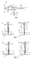
- An optical scanner having a micro-optical element 8 for beam combination is illustrated diagrammatically in Fig. 1.
- a twin laser diode 1 emits a first light beam 2a and a second light beam 2b.
- the light beams 2a, 2b are deflected via a half-mirror 4 in the direction of an optical recording medium 6 and collimated with the aid of a collimator lens 3.
- a movable objective lens 5 By means of a movable objective lens 5, the light beams 2a, 2b are focused onto a data track situated on the optical recording medium 6.
- the objective lens 5 can be moved by an actuator (not shown) in the direction of the optical recording medium 6 and also perpendicularly to the data track in order to keep the focus of the light beams 2a, 2b exactly on the track.
- the reflected light beams 2a, 2b which are modulated in accordance with the data stored in the track, are collimated by the objective lens 5 and focused onto a photodetector 9 by the collimator lens 3, passing through the half-mirror 4 in the process.
- the photodetector 9 has a plurality of light-sensitive elements separated by separating lines. The signals of said elements are used to determine, on the one hand, the stored data and, on the other hand, a focus error signal and a track error signal for controlling the actuator.
- a micro-optical element 8, 8' is situated upstream of the photodetector 9 and ensures that the two light beams 2a, 2b have the same position on the photodetector 9.
- Fig 2a shows a first exemplary embodiment of a micro-optical element 8 according to the invention.
- Fig. 2b shows an enlargement for illustrating the course of the light beams 2a, 2b.
- the illustration shows the basic idea of a micro-optical lens 8 in cross section.
- One area is that of a normal lens and the other area corresponds to the combination of two lenses.
- the cross-sectional area shown corresponds to the plane in which the source points of the light beams 2a, 2b are also located.
- the two light beams 2a, 2b are concentrated in this plane.
- it is possible to define the position of the focus by means of the focal length of the micro-optical lens 8.
- Fig. 3a illustrates an alternative arrangement of the micro-optical element 8.
- Fig. 3b) again shows an enlargement for illustrating the course of the light beams 2a, 2b.
- the roles of entry area and exit area have been interchanged in comparison with the exemplary embodiment illustrated in Fig. 2. Since the remaining path length to the photodetector 9 is shorter here, the two lens parts have to be separated further from one another.
- a certain minimum splitting of the light beams 2a, 2b must be ensured since, even in the event of a deflection of the objective lens 5 transversely with respect to the tracks of the optical recording medium 6, no light beam 2a, 2b is permitted to leave the lens area allocated to it.
- This arrangement is additionally advantageous since, in the event of a deflection of the objective lens 5 in the focus direction, the form of the light beams 2a, 2b is critically altered by the astigmatism caused essentially by the half-mirror 4 in the course of passing through it.
- the micro-optical lens 8 does not bear on the covering glass 10 of the photodetector 9.
- micro-optical lens 8 can also be displaced in the direction of the photodetector 9 to an extent such that its tip is located on the covering glass 10. Lateral supports are advantageous for the purpose of fixing on the covering glass 10.
- the micro-optical lens 8 and the supports can be injection-molded for example in a single step.
- a third exemplary embodiment of a micro-optical element 8' according to the invention is illustrated in the form of a double or roof prism in Fig. 4a) and b). Since the roof edge bears on the covering glass 10 of the photodetector 9, lateral supports are advantageous here, too.
- the entry area of the micro-optical element 8' is designed as a lens surface which is used to influence the size of the light beams 2a, 2b on the photodetector 9.
- the lens surface may be for example a spherical or a cylindrical area. In the case of a cylindrical area, the cylinder has to be arranged such that the plane of curvature corresponds to the sectional plane in which the prism angle is also situated.
- the roof edge is oriented along the separating line between the detector halves of the photodetector 9.
- the microscope reveals two images of the separating line which are located symmetrically about the roof edge.
- the use of a four-quadrant photodetector provides freedom to orient the roof edge at one of the two separating lines arranged in cross-shaped fashion. That separating line which lies parallel to the track deflection of the actuator is chosen for practical reasons. This ensures that the light beams 2a, 2b on the photodetector 9 are not cut off by the roof edge in the event of a track following movement. This also at the same time defines the orientation angle of the twin laser diode 1 as source of the light beams 2a, 2b.
- the light beams 2a, 2b on the photodetector 9 are spatially split. However, during the adjustment of the photodetector 9, a rotation of the twin laser diode 1 can be compensated for with a rotation of the photodetector 9.
- the different wavelengths used have no influence on the design of the double prism 8'.
- the roof edge can be placed centrally onto the separating line of the photodetector 9.
- a wavelength-dependent splitting of the light beams 2a, 2b on the photodetector 9 cannot be ascertained.
- the different refractive power of the double prism 8 for the two wavelengths used is negligible in the case of the short distances. This simplifies both the construction and the adjustment of the double prism 8'. If an adjustment-dictated parallel offset between the separating line and the roof edge arises, it does not affect the superposition of the light beams 2a, 2b on the photodetector 9. This fact makes it possible to merge double prism 8' and photodetector 9, as is shown in Fig. 5.
- the double prism 8' is already contained in the covering glass 10 of the photodetector 9.
- a focus offset that is possibly present also has only little influence on the superposition of the light beams 2a, 2b on the photodetector 9.
- a focus offset is a typical misadjustment of an optical scanner which may arise inter alia as a result of thermal loading or ageing. It is understood to be an incorrect position of one or else a plurality of optical components 3, 4, 5 in the direction of the light beam 2a, 2b, so that a focus in the information layer of the optical recording medium 6 no longer automatically results in a focus on the photodetector 9.
- the focus offset is generally compensated for by the servo-electronics.
- the superposition of the light beams 2a, 2b on the photodetector 9 is not impaired.
- the beam superposition exhibits a relatively sensitive behavior with respect to the distance between double prism 8' and photodetector 9. If the double prism 8' is simply placed onto the covering glass 10, the distance is readily reproducible and invariant with respect to ambient influences.
- Fig. 6 illustrates an optical adjustment element 11 for adjusting the spatial position of a light beam 2a, 2b.
- a plane-parallel plate 11 placed obliquely into a light beam generates a beam offset x.
- the beam offset is expressed with respect to the optical axis of the emerging beam 2a, 2b.
- the two light beams 2a, 2b of the twin laser diode 1 now traverse the plane-parallel plate 11.
- the difference ⁇ x in their respective beam offset is:
- n 1 and n 2 denote the refractive indices of the plate 11 at the two wavelengths of the twin laser diode 1. Since the refractive indices are close together, the following can be approximated:
- the exemplary embodiment shown in Fig. 7 will be explained below.
- the illustration shows the optical path of a scanner, in which the adjustment element is installed downstream of a half-mirror 4, in various adjustment states a), b) and c) produced by rotating the plate 11 about an axis.
- the linear range of the correction extends up to about 40° according to formula 3. Moreover, the correction becomes flatter. In the linear range, a spot correction of at most 3 ⁇ m results given a plate thickness of 1 mm. It is already worthwhile employing this correction in order to increase the performance of the scanner.
- the rotary range of the plate 11 should thus be designed to be very large.
- the plate 11 is advantageously an essentially plane-parallel plate. However, it may perfectly well be curved, too, thereby increasing the sensitivity. In the course of the adjustment, it is necessary to track the detector 9, which becomes clearly apparent from Fig. 7. The setting of the optical adjustment element 11 and the centering of the detector 9 are thus to be carried out progressively.
- the behavior of the S-curve is identical for positive or negative sense of rotation. Impairment of the servo electronics by a slightly lengthened S-curve is not expected. If only batch-dependent variations of the laser diode 1 are compensated for with relatively small angle changes, then these effects are not present.
Landscapes
- Physics & Mathematics (AREA)
- Optics & Photonics (AREA)
- General Physics & Mathematics (AREA)
- Optical Head (AREA)
- Mechanical Optical Scanning Systems (AREA)
- Optical Elements Other Than Lenses (AREA)
Abstract
Description
- The present invention relates to an optical scanner having a micro-optical element for combining two light beams and to an apparatus for reading from and/or writing to optical recording media which has such an optical scanner.
- Apparatuses for reading from and/or writing to optical recording media which are suitable for different types of optical recording media often require a plurality of beam sources which emit light beams having a different wavelength. One example is apparatuses for reading from and/or writing to DVDs (digital versatile disc), which are usually able to reproduce CDs (compact disc). Whereas a wavelength of 650 nm is used for the DVDs, the CDs are read with a wavelength of 780 nm. The development of optical drives operating with even shorter wavelengths, such as e.g. drives for Blu-Ray Disc, which operate with a wavelength of 405 nm, will also necessitate the use of a plurality of beam sources in the future.
- Many apparatuses use discrete laser diodes for generating the different wavelengths. However, many parts have to be used for such apparatuses, which is associated with high costs and a high adjustment outlay. High costs are caused especially by the required beam combination cube for combining the different light beams. An alternative is beam combiners based on optical gratings, as are described for example in WO 01/93254. However, gratings have a high degree of wavelength dependence, which can lead to problems if the wavelength of the laser diodes drifts with increasing temperature. Moreover, the gratings are not easy to produce since there are blazed gratings.
- So-called twin laser diodes are increasingly being used instead of discrete laser diodes. In the case of twin laser diodes, two laser diodes, e.g. for DVD and CD are arranged in a common housing, which entails advantages for the parts costs and production. Twin photodetectors having discrete photodetectors for the two light beams are often used in this case. According to present-day prior art, this concept cannot be applied to all types of optical storage media since correspondingly rapid twin photodetectors still do not exist for example for the high speeds occurring in the case of DVD-ROM.
- It is an object of the invention to propose an optical scanner which is improved compared with the prior art.
- According to the invention, this is achieved by means of an optical scanner having a micro-optical element comprising two parts and serving for combining two light beams emitted by two beam sources on a photodetector, the first part influencing the first light beam and the second part influencing the second light beam. The desired influencing is a deflection of one or both light beams toward a common target point. The distance between the two parts of the micro-optical element decides whether and where the continuing light beams meet. A prerequisite for the use of such a micro-optical element is that the light beams are separate upstream of the element. The use of a single lens is precluded in this case since the two light beams do not otherwise intersect at the focus. In order to obtain a producible element, in an advantageous manner, only those surface parts of the elements which actually contribute to beam influencing are taken into account.
- In an advantageous manner, the two parts of the micro-optical element are segments of a first and a second converging lens. The basic idea of a micro-optical lens for combining two light beams is that of a lens which arises conceptually from two lenses by pushing them together laterally apart from a specific distance. One part of the lens acts only on one light beam, and the other part on the other light beam. A tip results in the beam-free region between the light beams. It is preserved even when going over to practical lens forms. Of course, the tip may also be quarried, but only as far as is permitted by the separation of the light beams. Overall, the curve form is variable with only a slight effect on the quality of the imaging on the detector. Depending on the embodiment of the micro-optical lens, either the entry area or the exit area of the micro-optical lens is designed as a beam-influencing area. As an alternative, it is also possible for both areas to be embodied in beam-influencing fashion.
- The micro-optical element is preferably a double prism. The double prism or roof prism results from a micro-optical lens by using the straight line as the simplest form for the curve form of the lens area. The exit area of the micro-optical element is preferably embodied as the double prism since the separation of the light beams is greater there. In this case, the entry area of the micro-optical element may be designed as a lens surface which can be used to control the size of the light beam on the detector. The lens surface may be configured for example as a spherical or cylindrical area. The latter makes it possible to produce a perfectly round beam cross section on the photodetector area, which leads to a symmetrical S-curve. This is of importance for the servo electronics. In this case, the cylinder has to be rotated such that the plane of curvature corresponds to the plane in which the prism angle is also located.
- In accordance with a further exemplary embodiment, the micro-optical element is a cone. The cone represents a generalization of the idea of the double prism. One practical advantage resides in the simplification of the adjustment relative to the photodetector, since the angle dependence is obviated. However, the cone introduces an additional astigmatism. Its suitability as a micro-optical element must therefore be checked in the individual case. In the case of the cone as well, the exit area of the micro-optical element is preferably formed in a conical manner. The entry area may again be formed as a lens surface.
- The micro-optical element is advantageously arranged at the photodetector. The distance between the two light beams is greatest there, as a result of which the requirements made of the minimization of the micro-optics and the adjustment accuracy are reduced. As an alternative, the micro-optical element is arranged at the beam sources. There, too, the light beams are separated relatively far from one another, thus resulting in less stringent requirements made of the minimization of the micro-optics and the adjustment accuracy in this case as well. Depending on the embodiment, the micro-optical element may cause additional astigmatism in the light beams. An arrangement at the photodetector is preferable in such cases.
- The micro-optical element is preferably adhesively bonded to the photodetector. The micro-optical element has to be adjusted in the optical scanner. However, the element is very small and arranged near the photodetector, which likewise has to be adjusted, as a result of which the adjustment is made more difficult. However, the micro-optical element may be brought into direct contact with a covering glass of the photodetector. This requires a preadjustment under the microscope, during which the micro-optical element is oriented on the basis of the separating line of the detector areas. The micro-optical element is subsequently fixed on the covering glass by means of a process step, for example adhesive bonding. The adjustment of the photodetector remains as a normal process step in the production of optical scanners. The preadjustment of the micro-optical element has less stringent accuracy requirements than the adjustment of the photodetector since there is a tolerance range with respect to displacement and rotation of the micro-optical element.
- According to the invention, the micro-optical element is an integral part of the covering glass of the photodetector. This is possible, for example, by producing the micro-optical element and the covering glass as a unit by means of the plastic injection-molding method. The covering glass, normally embodied in plane fashion, is then structured. This constitutes a very elegant solution since the process of preadjustment is shifted to the mold for the detector housing.
- The beam sources are advantageously integrated to form a twin laser diode. This entails advantages for the parts costs and production. On the one hand, adjustment of the relative positions of the laser diodes is obviated and, on the other hand, it is possible to dispense with a cost-intensive beam combination cube. Moreover, most of the optical components of the optical scanner can be used for both light beams, so that fewer components are required overall.
- According to the invention, the micro-optical element influences the spatial position of only one of the light beams. The micro-optical element can be configured more simply in this way. Preferably, only the light beam that is less critical with respect to aberrations is deflected. Moreover, the different optical path length of the two light beams can also be utilized for compensating for an optical offset that is possibly present.
- For better adjustability of the light beams on the detector, it is advantageous if provision is made of an optical adjustment element which can be used to influence the spatial position of the first and/or the second light beam. Such an optical adjustment element is for example an essentially plane-parallel plate. As is known, a plane-parallel plate placed obliquely into a light beam generates a beam offset. The latter is dependent on the thickness d of the plate, the angle α of rotation of the plate and the refractive index n. If such a plane-parallel plate, situated only in the beam path of one of the light beams upstream of the detector, is rotated about an axis perpendicular to the light beam, that is to say the angle α is changed, then the position of the light beam on the detector changes. If such a plane-parallel plate is introduced into both beam paths, the positions of both light beams can be changed correspondingly. Moreover, the wavelength dependence of the refractive index of the plane-parallel plate can be utilized in order to adapt the distance between the two light beams. For this purpose, a common plate is used for both light beams. Since the refractive index is a function of the wavelength, a rotation of the plate leads to an offset between the two light beams which has a varying magnitude. The distance between the laser spots on the detector thus becomes adjustable. In the course of adjustment, it is necessary in this case to track the detector. The optical adjustment element is particularly advantageous for a so-called single detector, in which one detector is used for both light beams. However, it may equally be used in the case of a so-called twin detector, in which two detectors are combined to form a unit, for adjusting the light beams.
- As an alternative, the micro-optical element itself may also serve as the adjustment element. An effect analogous to the plane-parallel plate is achieved by rotating the roof prism, for example, about an axis parallel to the roof edge.
- An apparatus for reading from and/or writing to optical recording media preferably has an optical scanner according to the invention. Such an apparatus is able to use light beams having different wavelengths for reading from and/or writing to different types of optical recording media in a cost-effective manner.
- In order to provide a better understanding, the invention will be explained below on the basis of special exemplary embodiments with reference to the figures. It goes without saying that the invention is not restricted to the special exemplary embodiments. Advantageous combinations of the various features of the invention likewise lie within the scope of validity of the invention.
- Fig. 1
- diagrammatically shows an optical scanner having a micro-optical element for beam combination,
- Fig. 2
- shows a first exemplary embodiment of a micro-optical element according to the invention,
- Fig. 3
- shows a second exemplary embodiment of a micro-optical element according to the invention,
- Fig. 4
- shows a third exemplary embodiment of a micro-optical element according to the invention,
- Fig. 5
- shows a micro-optical element according to the invention which is integrated into the covering glass of a photodetector,
- Fig. 6
- shows an optical adjustment element for adjusting the spatial position of a light beam, and
- Fig. 7
- diagrammatically shows the functioning of the optical adjustment element.
- An optical scanner having a
micro-optical element 8 for beam combination is illustrated diagrammatically in Fig. 1. Atwin laser diode 1 emits afirst light beam 2a and a secondlight beam 2b. Thelight beams mirror 4 in the direction of an optical recording medium 6 and collimated with the aid of a collimator lens 3. By means of a movable objective lens 5, thelight beams light beams light beams photodetector 9 by the collimator lens 3, passing through the half-mirror 4 in the process. Thephotodetector 9 has a plurality of light-sensitive elements separated by separating lines. The signals of said elements are used to determine, on the one hand, the stored data and, on the other hand, a focus error signal and a track error signal for controlling the actuator. Amicro-optical element photodetector 9 and ensures that the twolight beams photodetector 9. - Fig 2a) shows a first exemplary embodiment of a
micro-optical element 8 according to the invention. Fig. 2b) shows an enlargement for illustrating the course of thelight beams micro-optical lens 8 in cross section. One area is that of a normal lens and the other area corresponds to the combination of two lenses. The cross-sectional area shown corresponds to the plane in which the source points of thelight beams light beams micro-optical lens 8. Independent of this is the centering of the twolight beams common photodetector area 9, which is achieved only by displacing the lens parts. In the illustrations shown, the influencing of thelight beams glass 10 of thephotodetector 9 is also taken into account. - Fig. 3a) illustrates an alternative arrangement of the
micro-optical element 8. Fig. 3b) again shows an enlargement for illustrating the course of thelight beams photodetector 9 is shorter here, the two lens parts have to be separated further from one another. - The nearer the
micro-optical element 8 is to the coveringglass 10, the further the splitting of thelight beams light beams light beam light beams mirror 4 in the course of passing through it. In the illustration, themicro-optical lens 8 does not bear on the coveringglass 10 of thephotodetector 9. It goes without saying that themicro-optical lens 8 can also be displaced in the direction of thephotodetector 9 to an extent such that its tip is located on the coveringglass 10. Lateral supports are advantageous for the purpose of fixing on the coveringglass 10. Themicro-optical lens 8 and the supports can be injection-molded for example in a single step. - A third exemplary embodiment of a
micro-optical element 8' according to the invention is illustrated in the form of a double or roof prism in Fig. 4a) and b). Since the roof edge bears on the coveringglass 10 of thephotodetector 9, lateral supports are advantageous here, too. In the figure, the entry area of themicro-optical element 8' is designed as a lens surface which is used to influence the size of thelight beams photodetector 9. The lens surface may be for example a spherical or a cylindrical area. In the case of a cylindrical area, the cylinder has to be arranged such that the plane of curvature corresponds to the sectional plane in which the prism angle is also situated. For the purpose of preadjustment, the roof edge is oriented along the separating line between the detector halves of thephotodetector 9. The microscope reveals two images of the separating line which are located symmetrically about the roof edge. The use of a four-quadrant photodetector provides freedom to orient the roof edge at one of the two separating lines arranged in cross-shaped fashion. That separating line which lies parallel to the track deflection of the actuator is chosen for practical reasons. This ensures that thelight beams photodetector 9 are not cut off by the roof edge in the event of a track following movement. This also at the same time defines the orientation angle of thetwin laser diode 1 as source of thelight beams light beams photodetector 9 are spatially split. However, during the adjustment of thephotodetector 9, a rotation of thetwin laser diode 1 can be compensated for with a rotation of thephotodetector 9. - The different wavelengths used, for example for DVD and CD, have no influence on the design of the
double prism 8'. Even in the case of a symmetrical embodiment of thedouble prism 8', the roof edge can be placed centrally onto the separating line of thephotodetector 9. A wavelength-dependent splitting of thelight beams photodetector 9 cannot be ascertained. The different refractive power of thedouble prism 8 for the two wavelengths used is negligible in the case of the short distances. This simplifies both the construction and the adjustment of thedouble prism 8'. If an adjustment-dictated parallel offset between the separating line and the roof edge arises, it does not affect the superposition of thelight beams photodetector 9. This fact makes it possible to mergedouble prism 8' andphotodetector 9, as is shown in Fig. 5. In the exemplary embodiment illustrated, thedouble prism 8' is already contained in the coveringglass 10 of thephotodetector 9. - A focus offset that is possibly present also has only little influence on the superposition of the
light beams photodetector 9. A focus offset is a typical misadjustment of an optical scanner which may arise inter alia as a result of thermal loading or ageing. It is understood to be an incorrect position of one or else a plurality ofoptical components 3, 4, 5 in the direction of thelight beam photodetector 9. In apparatuses for reading from and/or writing to optical recording media 6, the focus offset is generally compensated for by the servo-electronics. Even in the case of limit-value focus offsets, the superposition of thelight beams photodetector 9 is not impaired. However, the beam superposition exhibits a relatively sensitive behavior with respect to the distance betweendouble prism 8' andphotodetector 9. If thedouble prism 8' is simply placed onto the coveringglass 10, the distance is readily reproducible and invariant with respect to ambient influences. - Fig. 6 illustrates an
optical adjustment element 11 for adjusting the spatial position of alight beam parallel plate 11 placed obliquely into a light beam generates a beam offset x. The latter is dependent on the thickness d of the plate, the angle α of rotation of the plate and the refractive index n according to the following formula: - In this case, the beam offset is expressed with respect to the optical axis of the emerging
beam light beams twin laser diode 1 now traverse the plane-parallel plate 11. The difference Δx in their respective beam offset is:
- In this case, n1 and n2 denote the refractive indices of the
plate 11 at the two wavelengths of thetwin laser diode 1. Since the refractive indices are close together, the following can be approximated:
- The offset corresponds to the separation of the two optical axes downstream of the
plate 11. For an angle of rotation α = 0, all that remains is the offset. It should correspond to the distance between the detector areas for DVD and CD, for example. If not, it is possible to effect correction with Δx by setting an angle α of rotation at which the detector areas are impinged on correctly. In this case, the correction is proportional to (n1-n2 ), i.e. all the more effective, the more dispersive the material. - The exemplary embodiment shown in Fig. 7 will be explained below. The illustration shows the optical path of a scanner, in which the adjustment element is installed downstream of a half-
mirror 4, in various adjustment states a), b) and c) produced by rotating theplate 11 about an axis. Theplate 11 may be produced from plastic material, so that it can be injection-molded together with its rotary housing. There are materials where (n1-n2 ) = 0.01, the absolute index values always being 1.5. The linear range of the correction extends up to about 40° according to formula 3. Moreover, the correction becomes flatter. In the linear range, a spot correction of at most 3 µm results given a plate thickness of 1 mm. It is already worthwhile employing this correction in order to increase the performance of the scanner. The rotary range of theplate 11 should thus be designed to be very large. Theplate 11 is advantageously an essentially plane-parallel plate. However, it may perfectly well be curved, too, thereby increasing the sensitivity. In the course of the adjustment, it is necessary to track thedetector 9, which becomes clearly apparent from Fig. 7. The setting of theoptical adjustment element 11 and the centering of thedetector 9 are thus to be carried out progressively. - If it is necessary to greatly alter the angle α for using a laser diode from another manufacturer, then the spot size and the length of the S-curve can be increased on account of the astigmatism of the
plate 11. At an angle α = 0, these values are given only by an astigmatism of the half-mirror 4. The behavior of the S-curve is identical for positive or negative sense of rotation. Impairment of the servo electronics by a slightly lengthened S-curve is not expected. If only batch-dependent variations of thelaser diode 1 are compensated for with relatively small angle changes, then these effects are not present.
Claims (14)
- An optical scanner having a micro-optical element (8) for combining two light beams (2a, 2b) emitted by two beam sources (1) on a photodetector (9), wherein the micro-optical element (8, 8') has two parts, the first part influencing the first light beam (2a) and the second part influencing the second light beam (2b).
- The optical scanner as claimed in claim 1, wherein the two parts of the micro-optical element (8) are segments of a first and a second converging lens.
- The optical scanner as claimed in claim 1, wherein the micro-optical element is a double prism (8').
- The optical scanner as claimed in claim 1, wherein the micro-optical element is a cone.
- The optical scanner as claimed in one of the preceding claims, wherein the micro-optical element (8, 8') is arranged at the photodetector (9).
- The optical scanner as claimed in claim 5, wherein the micro-optical element (8, 8') forms a unit with the photodetector (9).
- The optical scanner as claimed in claim 5, wherein the micro-optical element (8, 8') is an integral part of a covering glass (10) of the photodetector (9).
- The optical scanner as claimed in one of claims 1-4, wherein the micro-optical element (8, 8') is arranged at the beam sources (1).
- The optical scanner as claimed in claim 8, wherein the beam sources (1) are integrated to form a twin laser diode (1).
- The optical scanner as claimed in one of the preceding claims, wherein the micro-optical element (8, 8') influences the spatial position of only one of the light beams (2a, 2b).
- The optical scanner as claimed in one of the preceding claims, wherein provision is made of an optical adjustment element (11) for adjusting the spatial position of the first and/or second light beam (2a, 2b).
- The optical scanner as claimed in claim 11, wherein the optical adjustment element (11) is an essentially plane-parallel plate.
- The optical scanner as claimed in claim 11, wherein the optical adjustment element (11) is the micro-optical element (8, 8').
- An apparatus for reading from and/or writing to optical recording media (6), wherein it has an optical scanner as claimed in one of claims 1-13.
Applications Claiming Priority (2)
| Application Number | Priority Date | Filing Date | Title |
|---|---|---|---|
| DE10330945A DE10330945A1 (en) | 2003-07-08 | 2003-07-08 | Optical scanner with micro-optics for beam combination |
| DE10330945 | 2003-07-08 |
Publications (1)
| Publication Number | Publication Date |
|---|---|
| EP1496506A1 true EP1496506A1 (en) | 2005-01-12 |
Family
ID=33441673
Family Applications (1)
| Application Number | Title | Priority Date | Filing Date |
|---|---|---|---|
| EP04300244A Withdrawn EP1496506A1 (en) | 2003-07-08 | 2004-04-29 | Optical scanner with micro-optics for beam combination |
Country Status (7)
| Country | Link |
|---|---|
| US (1) | US7265883B2 (en) |
| EP (1) | EP1496506A1 (en) |
| JP (1) | JP2005032418A (en) |
| KR (1) | KR20050006034A (en) |
| CN (1) | CN100363996C (en) |
| DE (1) | DE10330945A1 (en) |
| TW (1) | TW200504727A (en) |
Families Citing this family (2)
| Publication number | Priority date | Publication date | Assignee | Title |
|---|---|---|---|---|
| JP2010027148A (en) * | 2008-07-18 | 2010-02-04 | Sharp Corp | Optical pickup apparatus |
| US20120212592A1 (en) * | 2011-02-23 | 2012-08-23 | Precision Optics Corporation | Adjustment system for dipvergence and/or convergence of a stereoscopic image pair |
Citations (4)
| Publication number | Priority date | Publication date | Assignee | Title |
|---|---|---|---|---|
| US4886959A (en) * | 1986-11-27 | 1989-12-12 | Canon Kabushiki Kaisha | Optical information reproducing apparatus |
| US5216265A (en) * | 1990-12-05 | 1993-06-01 | Texas Instruments Incorporated | Integrated circuit memory devices with high angle implant around top of trench to reduce gated diode leakage |
| WO2001093254A1 (en) * | 2000-05-30 | 2001-12-06 | Thomson Licensing S.A. | Device for reading and/or writing optical recording media |
| US20020154591A1 (en) * | 2001-03-22 | 2002-10-24 | Satoru Sugawara | Optical module and optical recording and/or reproducing apparatus |
Family Cites Families (16)
| Publication number | Priority date | Publication date | Assignee | Title |
|---|---|---|---|---|
| DE3677658D1 (en) * | 1985-07-29 | 1991-04-04 | Mitsubishi Electric Corp | OPTICAL HEAD DEVICE. |
| DD242115A1 (en) * | 1985-11-01 | 1987-01-14 | Zeiss Jena Veb Carl | OPTICAL WRITING AND / OR READING HEAD FOR DATA CARRIER |
| US4835761A (en) * | 1985-11-20 | 1989-05-30 | Mitsubishi Denki Kabushiki Kaisha | Signal to noise ratio of optical head apparatus employing semiconductor laser beam source |
| US5251198A (en) * | 1992-05-29 | 1993-10-05 | Strickler James H | Reading device for multi-layered optical information carrier |
| JPH06169136A (en) * | 1992-11-30 | 1994-06-14 | Canon Inc | Light emitting device, optical semiconductor device and manufacture thereof |
| EP0831472B1 (en) * | 1996-03-11 | 2003-09-03 | Seiko Epson Corporation | Optical pickup and optical recording apparatus |
| KR100267233B1 (en) * | 1996-09-24 | 2000-10-16 | 윤종용 | Hologram optical pick-up device using the two-light source |
| US6256283B1 (en) * | 1996-10-01 | 2001-07-03 | Matsushita Electric Industrial Co., Ltd. | Optical pickup having a common light beam path for passing either of a plurality of kinds of light beams |
| JPH10199005A (en) * | 1996-12-26 | 1998-07-31 | Sony Corp | Optical pickup device |
| KR100294237B1 (en) * | 1998-04-14 | 2001-09-17 | 윤종용 | Optical pickup with catadioptric objectives |
| JP3422255B2 (en) * | 1998-06-10 | 2003-06-30 | 富士通株式会社 | Tracking device and optical disk device |
| EP1385026B1 (en) * | 1999-08-26 | 2007-01-24 | Asahi Glass Co., Ltd. | Optical head comprising a broadband retarder |
| JP3859416B2 (en) * | 2000-02-29 | 2006-12-20 | 株式会社日立製作所 | Objective lens, optical head and optical disk apparatus using the same |
| JP2001337227A (en) * | 2000-05-26 | 2001-12-07 | Ricoh Co Ltd | Polarization hologram element, semiconductor laser unit and optical pickup device |
| JP2002025096A (en) * | 2000-07-07 | 2002-01-25 | Matsushita Electric Ind Co Ltd | Semiconductor light source, optical pickup head device, and information recording / reproducing device |
| US6873589B2 (en) * | 2000-10-20 | 2005-03-29 | Sony Corporation | Method and device for detecting optical data and reading-writing apparatus for optical data |
-
2003
- 2003-07-08 DE DE10330945A patent/DE10330945A1/en not_active Withdrawn
-
2004
- 2004-04-29 EP EP04300244A patent/EP1496506A1/en not_active Withdrawn
- 2004-06-11 KR KR1020040042975A patent/KR20050006034A/en not_active Withdrawn
- 2004-06-17 TW TW093117419A patent/TW200504727A/en unknown
- 2004-07-06 CN CNB2004100634516A patent/CN100363996C/en not_active Expired - Fee Related
- 2004-07-07 JP JP2004200372A patent/JP2005032418A/en not_active Abandoned
- 2004-07-07 US US10/886,209 patent/US7265883B2/en not_active Expired - Fee Related
Patent Citations (4)
| Publication number | Priority date | Publication date | Assignee | Title |
|---|---|---|---|---|
| US4886959A (en) * | 1986-11-27 | 1989-12-12 | Canon Kabushiki Kaisha | Optical information reproducing apparatus |
| US5216265A (en) * | 1990-12-05 | 1993-06-01 | Texas Instruments Incorporated | Integrated circuit memory devices with high angle implant around top of trench to reduce gated diode leakage |
| WO2001093254A1 (en) * | 2000-05-30 | 2001-12-06 | Thomson Licensing S.A. | Device for reading and/or writing optical recording media |
| US20020154591A1 (en) * | 2001-03-22 | 2002-10-24 | Satoru Sugawara | Optical module and optical recording and/or reproducing apparatus |
Also Published As
| Publication number | Publication date |
|---|---|
| DE10330945A1 (en) | 2005-02-03 |
| US7265883B2 (en) | 2007-09-04 |
| CN1577543A (en) | 2005-02-09 |
| CN100363996C (en) | 2008-01-23 |
| US20050007640A1 (en) | 2005-01-13 |
| JP2005032418A (en) | 2005-02-03 |
| KR20050006034A (en) | 2005-01-15 |
| TW200504727A (en) | 2005-02-01 |
Similar Documents
| Publication | Publication Date | Title |
|---|---|---|
| US4789978A (en) | System and method of astigmatism correction in an optical head apparatus | |
| JPH07272301A (en) | Optical pickup device | |
| US7613082B2 (en) | Optical pickup device, optical recording and reproducing apparatus and gap detection method | |
| EP0198655A2 (en) | Optical heads | |
| WO2003007044A1 (en) | Objective lens, and optical pickup device using the objective lens | |
| US4965785A (en) | Optical head including a collimator having lenses of different focal lengths | |
| CN101401156B (en) | Lens driving device, optical pickup device and installation adjusting method | |
| US6995886B2 (en) | Optical scanning device | |
| US7265883B2 (en) | Optical scanner with micro-optics for beam combination | |
| KR20000069318A (en) | Device for optically scanning a record carrier | |
| KR20040068176A (en) | Optical scanning device | |
| JP2005535063A (en) | Scanning device including an objective lens formed of two kinds of materials | |
| JP2002533860A (en) | Optical scanning device | |
| JPH0434740A (en) | Optical head | |
| KR100603893B1 (en) | Optical scanning device of record carrier | |
| US7102981B2 (en) | Optical scanning device | |
| JP4929071B2 (en) | Optical element feeding device, optical pickup device, and optical disk device including the same | |
| JPH10334472A (en) | Optical pickup | |
| WO2007108446A1 (en) | Optical head, optical disc device and optical head manufacturing method | |
| JP4441101B2 (en) | Optical head for optical disk device | |
| US20050002288A1 (en) | Optical pickup device and method for controlling the same | |
| EP1776696A1 (en) | Initial focus optimization for an optical scanning device | |
| JP3810055B2 (en) | Optical disk device | |
| US20070051870A1 (en) | Optical pickup apparatus and information recording and reproducing apparatus | |
| JPH0850733A (en) | Optical apparatus |
Legal Events
| Date | Code | Title | Description |
|---|---|---|---|
| PUAI | Public reference made under article 153(3) epc to a published international application that has entered the european phase |
Free format text: ORIGINAL CODE: 0009012 |
|
| AK | Designated contracting states |
Kind code of ref document: A1 Designated state(s): AT BE BG CH CY CZ DE DK EE ES FI FR GB GR HU IE IT LI LU MC NL PL PT RO SE SI SK TR |
|
| AX | Request for extension of the european patent |
Extension state: AL HR LT LV MK |
|
| 17P | Request for examination filed |
Effective date: 20050704 |
|
| AKX | Designation fees paid |
Designated state(s): DE FR GB IT |
|
| RAP1 | Party data changed (applicant data changed or rights of an application transferred) |
Owner name: THOMSON LICENSING |
|
| RAP1 | Party data changed (applicant data changed or rights of an application transferred) |
Owner name: THOMSON LICENSING |
|
| STAA | Information on the status of an ep patent application or granted ep patent |
Free format text: STATUS: THE APPLICATION IS DEEMED TO BE WITHDRAWN |
|
| 18D | Application deemed to be withdrawn |
Effective date: 20101102 |