EP1496330A2 - Heat exchanger having header tanks - Google Patents
Heat exchanger having header tanks Download PDFInfo
- Publication number
- EP1496330A2 EP1496330A2 EP04015891A EP04015891A EP1496330A2 EP 1496330 A2 EP1496330 A2 EP 1496330A2 EP 04015891 A EP04015891 A EP 04015891A EP 04015891 A EP04015891 A EP 04015891A EP 1496330 A2 EP1496330 A2 EP 1496330A2
- Authority
- EP
- European Patent Office
- Prior art keywords
- tube
- insertion groove
- heat exchanger
- tubes
- header tank
- Prior art date
- Legal status (The legal status is an assumption and is not a legal conclusion. Google has not performed a legal analysis and makes no representation as to the accuracy of the status listed.)
- Withdrawn
Links
- 238000003780 insertion Methods 0.000 claims abstract description 102
- 230000037431 insertion Effects 0.000 claims abstract description 102
- 230000007246 mechanism Effects 0.000 claims description 10
- 238000004891 communication Methods 0.000 claims description 6
- 238000005219 brazing Methods 0.000 abstract description 25
- 239000000945 filler Substances 0.000 abstract description 17
- 229910052751 metal Inorganic materials 0.000 abstract description 17
- 239000002184 metal Substances 0.000 abstract description 17
- 230000004048 modification Effects 0.000 description 26
- 238000012986 modification Methods 0.000 description 26
- 239000012530 fluid Substances 0.000 description 9
- 230000015572 biosynthetic process Effects 0.000 description 4
- CURLTUGMZLYLDI-UHFFFAOYSA-N Carbon dioxide Chemical compound O=C=O CURLTUGMZLYLDI-UHFFFAOYSA-N 0.000 description 2
- 229910052782 aluminium Inorganic materials 0.000 description 2
- XAGFODPZIPBFFR-UHFFFAOYSA-N aluminium Chemical compound [Al] XAGFODPZIPBFFR-UHFFFAOYSA-N 0.000 description 2
- 230000000694 effects Effects 0.000 description 2
- 239000000463 material Substances 0.000 description 2
- 229910002092 carbon dioxide Inorganic materials 0.000 description 1
- 239000001569 carbon dioxide Substances 0.000 description 1
- 239000000498 cooling water Substances 0.000 description 1
- 238000001125 extrusion Methods 0.000 description 1
- 230000006872 improvement Effects 0.000 description 1
- 230000010354 integration Effects 0.000 description 1
- 238000004519 manufacturing process Methods 0.000 description 1
- 238000000034 method Methods 0.000 description 1
- 230000008569 process Effects 0.000 description 1
- 230000005855 radiation Effects 0.000 description 1
- 230000009467 reduction Effects 0.000 description 1
- 238000003466 welding Methods 0.000 description 1
Images


Classifications
-
- F—MECHANICAL ENGINEERING; LIGHTING; HEATING; WEAPONS; BLASTING
- F28—HEAT EXCHANGE IN GENERAL
- F28F—DETAILS OF HEAT-EXCHANGE AND HEAT-TRANSFER APPARATUS, OF GENERAL APPLICATION
- F28F9/00—Casings; Header boxes; Auxiliary supports for elements; Auxiliary members within casings
- F28F9/02—Header boxes; End plates
- F28F9/04—Arrangements for sealing elements into header boxes or end plates
- F28F9/16—Arrangements for sealing elements into header boxes or end plates by permanent joints, e.g. by rolling
- F28F9/18—Arrangements for sealing elements into header boxes or end plates by permanent joints, e.g. by rolling by welding
-
- F—MECHANICAL ENGINEERING; LIGHTING; HEATING; WEAPONS; BLASTING
- F28—HEAT EXCHANGE IN GENERAL
- F28D—HEAT-EXCHANGE APPARATUS, NOT PROVIDED FOR IN ANOTHER SUBCLASS, IN WHICH THE HEAT-EXCHANGE MEDIA DO NOT COME INTO DIRECT CONTACT
- F28D1/00—Heat-exchange apparatus having stationary conduit assemblies for one heat-exchange medium only, the media being in contact with different sides of the conduit wall, in which the other heat-exchange medium is a large body of fluid, e.g. domestic or motor car radiators
- F28D1/02—Heat-exchange apparatus having stationary conduit assemblies for one heat-exchange medium only, the media being in contact with different sides of the conduit wall, in which the other heat-exchange medium is a large body of fluid, e.g. domestic or motor car radiators with heat-exchange conduits immersed in the body of fluid
- F28D1/04—Heat-exchange apparatus having stationary conduit assemblies for one heat-exchange medium only, the media being in contact with different sides of the conduit wall, in which the other heat-exchange medium is a large body of fluid, e.g. domestic or motor car radiators with heat-exchange conduits immersed in the body of fluid with tubular conduits
- F28D1/053—Heat-exchange apparatus having stationary conduit assemblies for one heat-exchange medium only, the media being in contact with different sides of the conduit wall, in which the other heat-exchange medium is a large body of fluid, e.g. domestic or motor car radiators with heat-exchange conduits immersed in the body of fluid with tubular conduits the conduits being straight
- F28D1/0535—Heat-exchange apparatus having stationary conduit assemblies for one heat-exchange medium only, the media being in contact with different sides of the conduit wall, in which the other heat-exchange medium is a large body of fluid, e.g. domestic or motor car radiators with heat-exchange conduits immersed in the body of fluid with tubular conduits the conduits being straight the conduits having a non-circular cross-section
- F28D1/05366—Assemblies of conduits connected to common headers, e.g. core type radiators
- F28D1/05375—Assemblies of conduits connected to common headers, e.g. core type radiators with particular pattern of flow, e.g. change of flow direction
-
- F—MECHANICAL ENGINEERING; LIGHTING; HEATING; WEAPONS; BLASTING
- F28—HEAT EXCHANGE IN GENERAL
- F28F—DETAILS OF HEAT-EXCHANGE AND HEAT-TRANSFER APPARATUS, OF GENERAL APPLICATION
- F28F9/00—Casings; Header boxes; Auxiliary supports for elements; Auxiliary members within casings
- F28F9/02—Header boxes; End plates
- F28F9/0202—Header boxes having their inner space divided by partitions
Definitions
- the present invention relates to a heat exchanger having a pair of header tanks and a plurality of tubes inserted into the header tanks. More particularly, the invention relates to an attachment structure of the heat exchanger where the tubes are brazed to the header tanks.
- a heat exchanger In a heat exchanger, generally, a plurality of juxtaposed tubes are communicated with a pair of header tanks opposing to each other at an interval. Further, heat radiation fins are interposed between the adjoining tubes. In operation, heat exchange fluid flows from one header tank to the other header tank through the tubes. During this flowing of the heat exchange fluid, the heat exchanger carries out heat exchanging operation between the heat exchange fluid in the tubes and another heat exchange fluid passing through the fins.
- Japanese Patent Application Laid-open No. 11-351783 discloses a heat exchanger equipped with header tanks in which a plurality of cylindrical portions having substantially circular sections are juxtaposed in order to avoid concentration of stress due to high pressures, providing a multi-bore structure.
- the header tanks are is formed by extrusions, pressed goods, etc.
- each of the header tanks is provided by welding an inner member to an outer member by caulking.
- the outer member is provided with a plurality of insertion holes for the tubes.
- the tubes are inserted into the inner member through the insertion holes of the outer member and successively, the tubes are brazed to the outer member for integration.
- the inner member of the header tank has a plurality of insertion grooves formed therein at positions corresponding to the insertion holes of the outer member, then it becomes possible to engage respective ends of the tubes inserted into the insertion holes of the outer member with the insertion grooves of the inner member, thereby effecting both positioning and fixing of the tubes.
- each of the insertion grooves is formed so as to make its inside width equal to an inside width of the insertion groove, there is a possibility that when brazing the tubes to the header tanks, a molten brazing filler metal enters a clearance between the insertion groove of the inner member and the tube through a clearance between the insertion hole of the outer member and the tube. Consequently, due to the capillary phenomenon of the former clearance, the molten brazing filler metal further creeps in the back of the insertion groove and reaches the tip surface of the tube, so that an opening (communication part) at the tip of the tube may be clogged up with the molten brazing filler metal disadvantageously.
- the first aspect of the invention provides a heat exchanger comprising, a pair of header tanks arranged at a predetermined interval, each of the header tanks including an inner member having at least one insertion groove formed therein and an outer member having at least one insertion hole formed therein and covering the inner member thereby defining a hollow part in the header tank, and a plurality of tubes arranged between the header tanks in communication with the header tanks, each of the tubes having an end to be inserted into the insertion hole of the outer member of the header tank and also inserted into the insertion groove of the inner member of the header tank, wherein the insertion groove has a broad portion of which inside width is larger than an inside width of the insertion hole, wherein the tube is brazed to the outer member's part about the insertion hole.
- the heat exchanger of the first aspect owing to the formation of the broad portion of each insertion groove, it is possible to suppress capillary phenomenon of a molten brazing filler metal in a clearance between the inside member and the tube. Therefore, when brazing the tube to the periphery of the insertion hole of the outer member, the molten brazing filler metal does not reach the tip surface of the tube but remains in the broad portion, whereby it is possible to prevent an opening (or communication space) at the tip of the tube from being clogged with the brazing filler metal.
- the broad portion may be formed over the insertion groove. In this case, owing to the above formation of the broad portion, it becomes possible to suppress capillary phenomenon of the molten brazing filler metal in the clearance between the inside member and the tube.
- the broad portion may be formed at the bottom of the insertion groove. Then, owing to the broad portion, it is possible to fix the end portion of the tube with both of the insertion hole and an inlet portion of the insertion groove through the brazing filler metal. As a result, the joint strength of the tube with the inner member can be enhanced.
- the insertion groove is provided, at a bottom surface thereof, with a clearance forming mechanism configured to form a clearance between a tip surface of the tube and the bottom surface of the insertion groove.
- the clearance forming mechanism it is possible to prevent an opening at the tip of the tube from being blocked up by the bottom surface of the insertion groove.
- the clearance forming mechanism comprises the bottom surface of the insertion groove, which is inclined to the tip surface of the tube.
- the bottom surface inclined to the tip surface of the tube includes an arc-shaped section. Then, it is possible to prevent an opening at the tip of the tube from being blocked up by the bottom surface of the insertion groove. Additionally, it is also possible to braze the tube to the header tank while making the tip surface of the tube abut on the arc-shaped bottom surface of the insertion groove, whereby the tube can be assembled stably.
- the clearance forming mechanism comprises a recess formed on the bottom surface of the insertion groove, at a position opposing the tip surface of the tube.
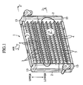
- the heat exchanger 1 generally includes a pair of hollow header tanks 2, 2, a plurality of flat tubes 3 paralleled with each other to straddle between the header tanks 2, 2 in communication with the header tanks 2, 2 and a plurality of fins 4 each disposed between the adjoining flat tubes 3 besides the outermost tubes 4.
- a heat exchange fluid such as cooling water
- the heat exchange is carried out between the above heat exchange fluid and another heat exchange fluid, for example, airflow passing through the fins 4.
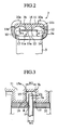
- the header tank 2 includes a U-shaped plate 10 as an outer member and a block 11 as an inner member.
- the plate 10 is provided by folding an aluminum clad material in a U-shaped manner by press working.
- the block 11 is provided by extruding an aluminum material. In assembling, the block 11 is first fitted to the interior side of the U-shaped plate 10 and successively, respective crimp portions 10a of the plate 10, which are in the form of comb teeth projecting on both sides of the plate 10, are crimped to both outer sides of the block 11, providing the header tank 2 in one body.
- the block 11 is provided, on its inner side close to the tubes 3 (lower side of Fig. 2), with a boundary wall 11a.
- a pair of groove parts 11b, 11b having substantial semicircular sections are defined on both sides of the boundary wall 11a.
- the insides of the groove parts 11b, 11b are covered by the plate 10 to form a pair of airtight cylindrical portions 12, 12. Owing to the provision of the cylindrical portions 12, 12, the header tank 10 is provided with a multi-hole structure.
- both ends of the header tank 10 are closed up by caps 13, as shown in Fig. 1.
- the plate 10 has insertion holes 14 formed to allow the tubes 3 to be inserted thereinto, as shown in Fig. 2. Further, the block 11 has insertion grooves 15 each formed with a predetermined depth D in the boundary wall 11a to engage with respective ends 3a of the tubes 3, respectively. While the ends 3a of the tubes 3 inserted into the insertion holes 14 are engaged with the insertion grooves 15, the tubes 3 are brazed to the peripheries of the insertion holes 14, ensuring the liquid-tight performance of the header tank 2.
- an appropriate clearance ⁇ 1 is defined between a tip surface 3b of each tube 3 and a bottom surface 15a of each insertion groove 15 to accomplish communication between the cylindrical portions 12, 12 on both sides of the boundary wall 11a.
- each insertion groove 15 is provided with a broad portion 16 whose inside width W2 is larger than an inside width W1 of the insertion hole 14 in the plate 10 in order to suppress the capillary phenomenon of molten brazing filler metal R in respective clearances ⁇ 2 each between the tube 3 and the inner wall of the insertion groove 15.
- the broad portion 16 is formed throughout the insertion groove 15.
- the molten brazing filler metal R stays in the broad portion 16 of the insertion groove 15 to form a fillet 17, so that it is possible to prevent the brazing filler metal R from reaching the tip surface of the tube 3. In other words, it is possible to prevent an opening at the tip of the tube 3 from being clogged up with the brazing filler metal R.
- Figs. 4 and 5 show the second embodiment of the present invention.
- elements identical to those of the first embodiment are indicated with the same reference numerals respectively and their overlapping descriptions are eliminated.
- Fig. 4 is an enlarged cross-sectional view of a substantial part of the header tank
- Fig. 5 is an enlarged longitudinal sectional view of the substantial part of the header tank.
- the broad portion 16 of the block 11 is formed at a bottom part 15b of the insertion groove 15.
- An inlet portion 15c of the insertion groove 15 is formed so that an inside width W3 is generally equal to the inside width W 1 of the insertion hole 14 of the plate 10.
- the end 3a of the tube 3 is positioned in the broad portion 16, it is possible to prevent the brazing filler metal R from reaching an opening at the tip of the tube 3, as similar to the first embodiment of the invention.
- the brazing filler metal R molten in brazing reaches the inlet portion 15c of the insertion groove 15. Consequently, it is possible to fix the end 3a of the tube 3 with both of the insertion hole 14 and the inlet portion 15c of the insertion groove 15, whereby the joint strength of the tube 3 with the header tank 2 can be enhanced.
- Fig. 6 shows the first modification of the second embodiment.
- elements identical to those of the second embodiment are indicated with the same reference numerals respectively and their overlapping descriptions are eliminated.
- Fig. 6 is an enlarged longitudinal sectional view of the substantial part of the header tank.
- the block 11 is provided, at an inlet of each insertion groove 15, with chamfers 15d, 15d. Therefore, owing to the provision of the chamfers 15d, 15d, it is possible to facilitate an insertion of the tube 3 into the insertion groove 15 in spite of the arrangement of the second embodiment where the inside width W3 of the inlet portion 15c of the insertion groove 15 is generally equal to the inside width W 1 of the insertion hole 14.
- each insertion groove 15 may be replaced by arc surfaces (not shown).
- Fig. 7 shows the third embodiment of the invention.
- elements identical to those of the previously-mentioned embodiments are indicated with the same reference numerals respectively and their overlapping descriptions are eliminated.
- Fig. 7 is an enlarged longitudinal sectional view of the substantial part of the header tank.
- the insertion groove 15 is provided, on the bottom surface 15a, with a clearance forming mechanism 18 configured to assure a clearance between the tip surface 3b of the tube 3 and the bottom surface 15a.
- the clearance forming mechanism 18 comprises a slanted surface 18a allowing the bottom surface 15a to be inclined to the tip surface 3b of the tube 3.
- the slanted surface 18a is inclined with respect to the bottom surface 15a of the insertion groove 15.
- Fig. 8 shows the first modification of the third embodiment.
- elements identical to those of the third embodiment are indicated with the same reference numerals respectively and their overlapping descriptions are eliminated.
- Fig. 8 is an enlarged longitudinal sectional view of the substantial part of the header tank.
- the above slanted surface 18a at the bottom surface 15a of the insertion groove 15 is shaped to have a substantially V-shaped section on a bottom's center position P opposing the tip surface 3b of the tube 3.
- the operation and effects of this modification are similar to those of the third embodiment mentioned above. Additionally, owing to the abutment of tube's corners (edges) on both sides of the tip surface 3b with the slanted surface 18a, the assembling of the tube 3 can be stabilized.
- a valley bottom of the slanted surface 18a may be further formed so as to be either flat or arc, providing a trapezoidal section.
- Fig. 9 shows the second modification of the third embodiment.
- elements identical to those of the third embodiment are indicated with the same reference numerals respectively and their overlapping descriptions are eliminated.
- Fig. 9 is an enlarged longitudinal sectional view of the substantial part of the header tank.
- the above slanted surface 18a at the bottom surface 15a of the insertion groove 15 has an arc-shaped section.
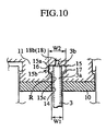
- Fig. 10 shows the third modification of the third embodiment.
- elements identical to those of the third embodiment are indicated with the same reference numerals respectively and their overlapping descriptions are eliminated.
- Fig. 10 is an enlarged longitudinal sectional view of the substantial part of the header tank.
- the above clearance forming mechanism 18 is formed by a recess 18b on the bottom surface 15a of the insertion groove 15.
- the recess 18b is also arranged at a bottom's position opposing the tip surface 3b of the tube 3.
- the recess 18b is formed to penetrate the boundary wall 11a (Fig. 2) thereby communicating the cylindrical portions 12, 12 (Fig. 2) with each other.
- the width of the recess 18b is established smaller than a width of the so-flattened tube 3 in the short-axis direction, thereby preventing the leading end of the tube 3 from entering the recess 18b.
- the tip surface 3b of the tube 3 is blocked up by the bottom surface 15a of the insertion groove 15 although the tube 3 abuts on the bottom surface 15a of the insertion groove 15.
Landscapes
- Engineering & Computer Science (AREA)
- Physics & Mathematics (AREA)
- Thermal Sciences (AREA)
- Mechanical Engineering (AREA)
- General Engineering & Computer Science (AREA)
- Details Of Heat-Exchange And Heat-Transfer (AREA)
Abstract
A heat exchanger (1) includes a pair of header tanks (2) and a plurality of
tubes (3). Each of the header tanks (2) includes an outer member (10) and an inner
member (11). The outer member (10) has insertion holes (14) allowing insertion of the
tubes (3), while the inner member (11) has insertion grooves (15) allowing insertion of
respective ends of the tubes (3). The heat exchanger (1) is provided by brazing
the so-inserted tubes (3) to the peripheries of the insertion holes (14) of the outer
member (10). In order to suppress capillary phenomenon of a molten brazing
filler metal in a clearance between each insertion groove (15) and the tube (3), a
broad portion (16) is formed in the insertion groove (15) to have an inside width
larger than an inside width of the insertion hole (14). When brazing the tube (3) to
the outer member (10) and the inner member (11), the molten brazing filler metal
does not reach the tip surface of the tube (3) but remains in the broad portion (16)
while maintaining the brazing strength of the tube (3).
Description
- The present invention relates to a heat exchanger having a pair of header tanks and a plurality of tubes inserted into the header tanks. More particularly, the invention relates to an attachment structure of the heat exchanger where the tubes are brazed to the header tanks.
- In a heat exchanger, generally, a plurality of juxtaposed tubes are communicated with a pair of header tanks opposing to each other at an interval. Further, heat radiation fins are interposed between the adjoining tubes. In operation, heat exchange fluid flows from one header tank to the other header tank through the tubes. During this flowing of the heat exchange fluid, the heat exchanger carries out heat exchanging operation between the heat exchange fluid in the tubes and another heat exchange fluid passing through the fins.
- Meanwhile, when carbon dioxide gas as one supercritical fluid is used for the heat exchange fluid for refrigerating cycle and heat pump cycle, it is necessary to assure a sufficient flame-proof strength for the header tanks due to an increased interior pressure in the heat exchanger. For this purpose, Japanese Patent Application Laid-open No. 11-351783 discloses a heat exchanger equipped with header tanks in which a plurality of cylindrical portions having substantially circular sections are juxtaposed in order to avoid concentration of stress due to high pressures, providing a multi-bore structure. In this view, the header tanks are is formed by extrusions, pressed goods, etc.
- In the heat exchanger, each of the header tanks is provided by welding an inner member to an outer member by caulking. The outer member is provided with a plurality of insertion holes for the tubes. In assembling, the tubes are inserted into the inner member through the insertion holes of the outer member and successively, the tubes are brazed to the outer member for integration.
- In the above-mentioned heat exchanger, if the inner member of the header tank has a plurality of insertion grooves formed therein at positions corresponding to the insertion holes of the outer member, then it becomes possible to engage respective ends of the tubes inserted into the insertion holes of the outer member with the insertion grooves of the inner member, thereby effecting both positioning and fixing of the tubes.
- In connection, if each of the insertion grooves is formed so as to make its inside width equal to an inside width of the insertion groove, there is a possibility that when brazing the tubes to the header tanks, a molten brazing filler metal enters a clearance between the insertion groove of the inner member and the tube through a clearance between the insertion hole of the outer member and the tube. Consequently, due to the capillary phenomenon of the former clearance, the molten brazing filler metal further creeps in the back of the insertion groove and reaches the tip surface of the tube, so that an opening (communication part) at the tip of the tube may be clogged up with the molten brazing filler metal disadvantageously.
- In the above-mentioned situation, it is an object of the present invention to provide a heat exchanger that can prevent the molten brazing filler metal from reaching the tip surfaces of the tubes in insertion into the insertion grooves of the inner member while assuring the brazing strength about the tubes.
- To attain the above object, the first aspect of the invention provides a heat exchanger comprising, a pair of header tanks arranged at a predetermined interval, each of the header tanks including an inner member having at least one insertion groove formed therein and an outer member having at least one insertion hole formed therein and covering the inner member thereby defining a hollow part in the header tank, and a plurality of tubes arranged between the header tanks in communication with the header tanks, each of the tubes having an end to be inserted into the insertion hole of the outer member of the header tank and also inserted into the insertion groove of the inner member of the header tank, wherein the insertion groove has a broad portion of which inside width is larger than an inside width of the insertion hole, wherein the tube is brazed to the outer member's part about the insertion hole.
- In the heat exchanger of the first aspect, owing to the formation of the broad portion of each insertion groove, it is possible to suppress capillary phenomenon of a molten brazing filler metal in a clearance between the inside member and the tube. Therefore, when brazing the tube to the periphery of the insertion hole of the outer member, the molten brazing filler metal does not reach the tip surface of the tube but remains in the broad portion, whereby it is possible to prevent an opening (or communication space) at the tip of the tube from being clogged with the brazing filler metal.
- In a preferred embodiment, the broad portion may be formed over the insertion groove. In this case, owing to the above formation of the broad portion, it becomes possible to suppress capillary phenomenon of the molten brazing filler metal in the clearance between the inside member and the tube.
- The broad portion may be formed at the bottom of the insertion groove. Then, owing to the broad portion, it is possible to fix the end portion of the tube with both of the insertion hole and an inlet portion of the insertion groove through the brazing filler metal. As a result, the joint strength of the tube with the inner member can be enhanced.
- The insertion groove is provided, at a bottom surface thereof, with a clearance forming mechanism configured to form a clearance between a tip surface of the tube and the bottom surface of the insertion groove.
- Then, by the clearance forming mechanism, it is possible to prevent an opening at the tip of the tube from being blocked up by the bottom surface of the insertion groove.
- The clearance forming mechanism comprises the bottom surface of the insertion groove, which is inclined to the tip surface of the tube.
- Similarly, it is possible to prevent an opening at the tip of the tube from being blocked up by the bottom surface of the insertion groove. Additionally, it is also possible to braze the tube to the header tank while making the tip surface of the tube abut on the bottom surface of the insertion groove, whereby the assembling workability can be improved.
- The bottom surface inclined to the tip surface of the tube includes an arc-shaped section. Then, it is possible to prevent an opening at the tip of the tube from being blocked up by the bottom surface of the insertion groove. Additionally, it is also possible to braze the tube to the header tank while making the tip surface of the tube abut on the arc-shaped bottom surface of the insertion groove, whereby the tube can be assembled stably.
- The clearance forming mechanism comprises a recess formed on the bottom surface of the insertion groove, at a position opposing the tip surface of the tube.
- Owing to the formation of the recess on the bottom face of the insertion groove, it is possible to prevent an opening at the tip of the tube from being blocked up by the bottom surface of the insertion groove.
- These and other objects and features of the present invention will become more fully apparent from the following description and appended claims taken in conjunction with the accompanying drawings.
-
- Fig. 1 is a perspective view of a heat exchanger in accordance with the first embodiment of the present invention;
- Fig. 2 is an enlarged cross-sectional view of a header tank, taken along a line 2-2 of Fig. 1;
- Fig. 3 is an enlarged longitudinal sectional view of the header tank, taken along a line 3-3 of Fig. 1;
- Fig. 4 is an enlarged cross-sectional view of a substantial part of the header tank in accordance with the second embodiment of the present invention;
- Fig. 5 is an enlarged longitudinal sectional view of the substantial part of the header tank in accordance with the second embodiment of the present invention;
- Fig. 6 is an enlarged longitudinal sectional view of the substantial part of the header tank in the first modification of the second embodiment of the present invention;
- Fig. 7 is an enlarged longitudinal sectional view of the substantial part of the header tank in accordance with the third embodiment of the present invention;
- Fig. 8 is an enlarged longitudinal sectional view of the substantial part of the header tank in the first modification of the third embodiment of the present invention;
- Fig. 9 is an enlarged longitudinal sectional view of the substantial part of the header tank in the second modification of the third embodiment of the present invention; and
- Fig. 10 is an enlarged longitudinal sectional view of the substantial part of the header tank in the third modification of the third embodiment of the present invention.
-
- Referring to accompanying drawings, embodiments of the present invention will be described below.
- According to this embodiment, as shown in Fig. 1, the
heat exchanger 1 generally includes a pair ofhollow header tanks flat tubes 3 paralleled with each other to straddle between theheader tanks header tanks flat tubes 3 besides the outermost tubes 4. In theheat exchanger 1, a heat exchange fluid such as cooling water, flows from oneheader tank 2 to theother header tank 2 through the intermediary of thetubes 3. During this flowing, the heat exchange is carried out between the above heat exchange fluid and another heat exchange fluid, for example, airflow passing through the fins 4. - As shown in Fig. 2, the
header tank 2 includes a U-shapedplate 10 as an outer member and ablock 11 as an inner member. Theplate 10 is provided by folding an aluminum clad material in a U-shaped manner by press working. On the other hand, theblock 11 is provided by extruding an aluminum material. In assembling, theblock 11 is first fitted to the interior side of the U-shapedplate 10 and successively,respective crimp portions 10a of theplate 10, which are in the form of comb teeth projecting on both sides of theplate 10, are crimped to both outer sides of theblock 11, providing theheader tank 2 in one body. - The
block 11 is provided, on its inner side close to the tubes 3 (lower side of Fig. 2), with aboundary wall 11a. A pair ofgroove parts boundary wall 11a. The insides of thegroove parts plate 10 to form a pair of airtightcylindrical portions cylindrical portions header tank 10 is provided with a multi-hole structure. - Of course, both ends of the
header tank 10 are closed up bycaps 13, as shown in Fig. 1. - The
plate 10 has insertion holes 14 formed to allow thetubes 3 to be inserted thereinto, as shown in Fig. 2. Further, theblock 11 hasinsertion grooves 15 each formed with a predetermined depth D in theboundary wall 11a to engage withrespective ends 3a of thetubes 3, respectively. While theends 3a of thetubes 3 inserted into the insertion holes 14 are engaged with theinsertion grooves 15, thetubes 3 are brazed to the peripheries of the insertion holes 14, ensuring the liquid-tight performance of theheader tank 2. - In such an assembling state between the
tubes 3 and theheader tank 2, anappropriate clearance δ 1 is defined between atip surface 3b of eachtube 3 and abottom surface 15a of eachinsertion groove 15 to accomplish communication between thecylindrical portions boundary wall 11a. - According to the first embodiment of the invention, as shown in Fig. 3, each
insertion groove 15 is provided with abroad portion 16 whose inside width W2 is larger than an inside width W1 of theinsertion hole 14 in theplate 10 in order to suppress the capillary phenomenon of molten brazing filler metal R in respective clearances δ 2 each between thetube 3 and the inner wall of theinsertion groove 15. - Additionally, it is noted that the
broad portion 16 is formed throughout theinsertion groove 15. - With the above-mentioned structure, owing to the provision of the
insertion groove 15 with thebroad portion 16 having its inside width W2 larger than the inside width W1 of theinsertion hole 14, when brazing theinsertion hole 14 of theplate 10 to thetube 3 inserted thereinto, the molten brazing filler metal R stays in thebroad portion 16 of theinsertion groove 15 to form afillet 17, so that it is possible to prevent the brazing filler metal R from reaching the tip surface of thetube 3. In other words, it is possible to prevent an opening at the tip of thetube 3 from being clogged up with the brazing filler metal R. - Again, since the
broad portion 16 is formed throughout theinsertion groove 15 in this embodiment, there is produced a dimensional room between thetube 3 and theinsertion groove 15 in engaging theend 3a of thetube 3 in theinsertion groove 15 via theinsertion hole 14. That is, since the assembling of theplate 10 with theblock 11 does not require to form these elements (i.e. thegrooves 15, thetubes 3, etc.) with high dimensional accuracy, it is possible to attain an improvement in productivity and a reduction in manufacturing cost. - Figs. 4 and 5 show the second embodiment of the present invention. In the second embodiment, elements identical to those of the first embodiment are indicated with the same reference numerals respectively and their overlapping descriptions are eliminated. In those figures, Fig. 4 is an enlarged cross-sectional view of a substantial part of the header tank, while Fig. 5 is an enlarged longitudinal sectional view of the substantial part of the header tank.
- According to the second embodiment of the invention, the
broad portion 16 of theblock 11 is formed at abottom part 15b of theinsertion groove 15. - An
inlet portion 15c of theinsertion groove 15 is formed so that an inside width W3 is generally equal to theinside width W 1 of theinsertion hole 14 of theplate 10. - Thus, according to the second embodiment of the invention, since the
end 3a of thetube 3 is positioned in thebroad portion 16, it is possible to prevent the brazing filler metal R from reaching an opening at the tip of thetube 3, as similar to the first embodiment of the invention. Particularly, since it is possible to make the inside width W3 at theinlet portion 15c of theinsertion groove 15 generally equal to the inside W1 of theinsertion hole 15 of theplate 10, the brazing filler metal R molten in brazing reaches theinlet portion 15c of theinsertion groove 15. Consequently, it is possible to fix theend 3a of thetube 3 with both of theinsertion hole 14 and theinlet portion 15c of theinsertion groove 15, whereby the joint strength of thetube 3 with theheader tank 2 can be enhanced. - Fig. 6 shows the first modification of the second embodiment. In the first modification, elements identical to those of the second embodiment are indicated with the same reference numerals respectively and their overlapping descriptions are eliminated. Fig. 6 is an enlarged longitudinal sectional view of the substantial part of the header tank.
- According to the modification, the
block 11 is provided, at an inlet of eachinsertion groove 15, withchamfers chamfers tube 3 into theinsertion groove 15 in spite of the arrangement of the second embodiment where the inside width W3 of theinlet portion 15c of theinsertion groove 15 is generally equal to theinside width W 1 of theinsertion hole 14. - In a further modification, the "straight"
chamfers insertion groove 15 may be replaced by arc surfaces (not shown). - Fig. 7 shows the third embodiment of the invention. In the third embodiment, elements identical to those of the previously-mentioned embodiments are indicated with the same reference numerals respectively and their overlapping descriptions are eliminated. Fig. 7 is an enlarged longitudinal sectional view of the substantial part of the header tank.
- According to the third embodiment, as shown in Fig. 7, the
insertion groove 15 is provided, on thebottom surface 15a, with aclearance forming mechanism 18 configured to assure a clearance between thetip surface 3b of thetube 3 and thebottom surface 15a. - In detail, the
clearance forming mechanism 18 comprises aslanted surface 18a allowing thebottom surface 15a to be inclined to thetip surface 3b of thetube 3. - It is noted in this embodiment that the
slanted surface 18a is inclined with respect to thebottom surface 15a of theinsertion groove 15. - In assembling the
tubes 3 to theheader tanks 2, according to the third embodiment, even if thetip surface 3b of thetube 3 abuts on thebottom surface 15a of theinsertion groove 15 in the process of engaging thetube 3 with theinsertion groove 15 of theblock 11 via theinsertion hole 14 of theplate 10, it is possible to prevent an opening at the tip of thetube 3 from being blocked up by thebottom surface 15a of theinsertion groove 15 due to the formation of the slantedsurface 18a (the bottom surface15a). - In other words, since the above-mentioned arrangement of this embodiment allows the
tube 3 to be brazed to theheader tank 2 under condition that thetip surface 3b of thetube 3 is abutting on thebottom surface 15a of theinsertion groove 15, it is possible to improve the assembling workability. - Fig. 8 shows the first modification of the third embodiment. In the first modification, elements identical to those of the third embodiment are indicated with the same reference numerals respectively and their overlapping descriptions are eliminated. Fig. 8 is an enlarged longitudinal sectional view of the substantial part of the header tank.
- In this modification, as shown in Fig. 8, the above slanted
surface 18a at thebottom surface 15a of theinsertion groove 15 is shaped to have a substantially V-shaped section on a bottom's center position P opposing thetip surface 3b of thetube 3. - Since the
tip surface 3b of thetube 3 abuts on the V-shapedslanted surface 18a, the operation and effects of this modification are similar to those of the third embodiment mentioned above. Additionally, owing to the abutment of tube's corners (edges) on both sides of thetip surface 3b with theslanted surface 18a, the assembling of thetube 3 can be stabilized. - Alternatively, a valley bottom of the slanted
surface 18a may be further formed so as to be either flat or arc, providing a trapezoidal section. - Fig. 9 shows the second modification of the third embodiment. In the second modification, elements identical to those of the third embodiment are indicated with the same reference numerals respectively and their overlapping descriptions are eliminated. Fig. 9 is an enlarged longitudinal sectional view of the substantial part of the header tank.
- In this modification, as shown in Fig. 9, the above slanted
surface 18a at thebottom surface 15a of theinsertion groove 15 has an arc-shaped section. - Since the
tip surface 3b of thetube 3 abuts on the arc-shapedslanted surface 18a, the operation and effects of this modification are similar to those of the third embodiment mentioned above. As similar to the first modification, owing to the abutment of tube's corners (edges) on both sides of thetip surface 3a with the arc-shapedsurface 18a, the assembling of thetube 3 can be stabilized. - Fig. 10 shows the third modification of the third embodiment. In the third modification, elements identical to those of the third embodiment are indicated with the same reference numerals respectively and their overlapping descriptions are eliminated. Fig. 10 is an enlarged longitudinal sectional view of the substantial part of the header tank.
- According to this modification, the above
clearance forming mechanism 18 is formed by arecess 18b on thebottom surface 15a of theinsertion groove 15. Therecess 18b is also arranged at a bottom's position opposing thetip surface 3b of thetube 3. - Also noted that the
recess 18b is formed to penetrate theboundary wall 11a (Fig. 2) thereby communicating thecylindrical portions 12, 12 (Fig. 2) with each other. Of course, the width of therecess 18b is established smaller than a width of the so-flattenedtube 3 in the short-axis direction, thereby preventing the leading end of thetube 3 from entering therecess 18b. - According to the third modification, owing to the provision of the
recess 18b, it is possible to prevent thetip surface 3b of thetube 3 from being blocked up by thebottom surface 15a of theinsertion groove 15 although thetube 3 abuts on thebottom surface 15a of theinsertion groove 15. - Finally, it will be understood by those skilled in the art that the foregoing descriptions are nothing but three embodiments of the disclosed heat exchanger and therefore, various changes and modifications may be made within the scope of claims.
Claims (7)
- A heat exchanger comprising:wherein the insertion groove has a broad portion of which inside width is larger than an inside width of the insertion hole,a pair of header tanks arranged at a predetermined interval, each of the header tanks including an inner member having at least one insertion groove formed therein and an outer member having at least one insertion hole formed therein and covering the inner member thereby defining a hollow part in the header tank; anda plurality of tubes arranged between the header tanks in communication with the header tanks, each of the tubes having an end to be inserted into the insertion hole of the outer member of the header tank and also inserted into the insertion groove of the inner member of the header tank,
wherein the tube is brazed to the outer member's part about the insertion hole. - The heat exchanger of claim 1, wherein the broad portion is formed over the insertion groove.
- The heat exchanger of claim 1, wherein the broad portion is formed at the bottom of the insertion groove.
- The heat exchanger of claim 1, wherein the insertion groove is provided, at a bottom surface thereof, with a clearance forming mechanism configured to form a clearance between a tip surface of the tube and the bottom surface of the insertion groove.
- The heat exchanger of claim 4, wherein the clearance forming mechanism comprises the bottom surface of the insertion groove, which is inclined to the tip surface of the tube.
- The heat exchanger of claim 5, wherein the bottom surface inclined to the tip surface of the tube comprises an arc-shaped section.
- The heat exchanger of claim 4, wherein the clearance forming mechanism comprises a recess formed on the bottom surface of the insertion groove, at a position opposing to the tip surface of the tube.
Applications Claiming Priority (2)
| Application Number | Priority Date | Filing Date | Title |
|---|---|---|---|
| JP2003271601A JP2005030700A (en) | 2003-07-07 | 2003-07-07 | Tube fixing part structure of heat exchanger |
| JP2003271601 | 2003-07-07 |
Publications (1)
| Publication Number | Publication Date |
|---|---|
| EP1496330A2 true EP1496330A2 (en) | 2005-01-12 |
Family
ID=33448042
Family Applications (1)
| Application Number | Title | Priority Date | Filing Date |
|---|---|---|---|
| EP04015891A Withdrawn EP1496330A2 (en) | 2003-07-07 | 2004-07-06 | Heat exchanger having header tanks |
Country Status (3)
| Country | Link |
|---|---|
| US (1) | US20050051316A1 (en) |
| EP (1) | EP1496330A2 (en) |
| JP (1) | JP2005030700A (en) |
Cited By (2)
| Publication number | Priority date | Publication date | Assignee | Title |
|---|---|---|---|---|
| EP1857763A3 (en) * | 2006-05-18 | 2012-08-22 | Doowon Climate Control Co., Ltd | Header for high pressure heat exchanger |
| WO2021082149A1 (en) * | 2019-10-30 | 2021-05-06 | 广东美的制冷设备有限公司 | Heat exchanger and air conditioner provided with same |
Families Citing this family (1)
| Publication number | Priority date | Publication date | Assignee | Title |
|---|---|---|---|---|
| EP2107328B1 (en) * | 2008-04-02 | 2012-07-11 | Behr GmbH & Co. KG | Vaporiser |
Citations (1)
| Publication number | Priority date | Publication date | Assignee | Title |
|---|---|---|---|---|
| JPH11351783A (en) | 1998-04-08 | 1999-12-24 | Denso Corp | Heat exchanger |
Family Cites Families (8)
| Publication number | Priority date | Publication date | Assignee | Title |
|---|---|---|---|---|
| JPH02115689U (en) * | 1989-03-06 | 1990-09-17 | ||
| US5544698A (en) * | 1994-03-30 | 1996-08-13 | Peerless Of America, Incorporated | Differential coatings for microextruded tubes used in parallel flow heat exchangers |
| JPH11226685A (en) * | 1998-02-16 | 1999-08-24 | Denso Corp | Method of manufacturing heat exchanger and header tank |
| US6216776B1 (en) * | 1998-02-16 | 2001-04-17 | Denso Corporation | Heat exchanger |
| FR2793014B1 (en) * | 1999-04-28 | 2001-07-27 | Valeo Thermique Moteur Sa | HEAT EXCHANGER FOR HIGH PRESSURE FLUID |
| US6745827B2 (en) * | 2001-09-29 | 2004-06-08 | Halla Climate Control Corporation | Heat exchanger |
| JP4107051B2 (en) * | 2002-02-19 | 2008-06-25 | 株式会社デンソー | Heat exchanger |
| US6446713B1 (en) * | 2002-02-21 | 2002-09-10 | Norsk Hydro, A.S. | Heat exchanger manifold |
-
2003
- 2003-07-07 JP JP2003271601A patent/JP2005030700A/en not_active Withdrawn
-
2004
- 2004-07-06 US US10/885,361 patent/US20050051316A1/en not_active Abandoned
- 2004-07-06 EP EP04015891A patent/EP1496330A2/en not_active Withdrawn
Patent Citations (1)
| Publication number | Priority date | Publication date | Assignee | Title |
|---|---|---|---|---|
| JPH11351783A (en) | 1998-04-08 | 1999-12-24 | Denso Corp | Heat exchanger |
Cited By (2)
| Publication number | Priority date | Publication date | Assignee | Title |
|---|---|---|---|---|
| EP1857763A3 (en) * | 2006-05-18 | 2012-08-22 | Doowon Climate Control Co., Ltd | Header for high pressure heat exchanger |
| WO2021082149A1 (en) * | 2019-10-30 | 2021-05-06 | 广东美的制冷设备有限公司 | Heat exchanger and air conditioner provided with same |
Also Published As
| Publication number | Publication date |
|---|---|
| US20050051316A1 (en) | 2005-03-10 |
| JP2005030700A (en) | 2005-02-03 |
Similar Documents
| Publication | Publication Date | Title |
|---|---|---|
| KR100274586B1 (en) | Heat exchanger | |
| JP4602714B2 (en) | Heat exchanger | |
| JP2001289590A (en) | Heat exchanger | |
| JP2007298197A (en) | Heat exchanger | |
| JP3329893B2 (en) | Heat exchanger header tank | |
| JPH11351783A (en) | Heat exchanger | |
| JP2006189205A (en) | Heat exchanger | |
| JPH06229696A (en) | Heat exchanger | |
| JP4217469B2 (en) | Heat exchanger | |
| US20050051316A1 (en) | Heat exchanger having header tanks | |
| US6604574B1 (en) | Two-piece header and heat exchanger incorporating same | |
| JPH07318288A (en) | Heat exchanger tank partition structure | |
| EP0805330B1 (en) | Heat exchanger enabling leak test of chambers in tank separated by single partition | |
| JP2008249241A (en) | Heat exchanger | |
| JP4541009B2 (en) | Heat exchanger | |
| JP4866571B2 (en) | Heat exchanger | |
| JPH09280774A (en) | Heat exchanger | |
| EP1420222A1 (en) | Heat exchanger | |
| JP2005249332A (en) | Double heat exchanger | |
| US20020020522A1 (en) | Folded tube for heat exchanger, and heat exchanger including such tubes | |
| JP2009047401A (en) | Header tank structure for heat exchanger | |
| JP4715188B2 (en) | Heat exchanger | |
| JP4787511B2 (en) | Joining structure of heat exchanger and joining method thereof | |
| JP4218349B2 (en) | Heat exchanger | |
| JP2006214656A (en) | Heat exchanger joint structure |
Legal Events
| Date | Code | Title | Description |
|---|---|---|---|
| PUAI | Public reference made under article 153(3) epc to a published international application that has entered the european phase |
Free format text: ORIGINAL CODE: 0009012 |
|
| AK | Designated contracting states |
Kind code of ref document: A2 Designated state(s): AT BE BG CH CY CZ DE DK EE ES FI FR GB GR HU IE IT LI LU MC NL PL PT RO SE SI SK TR |
|
| AX | Request for extension of the european patent |
Extension state: AL HR LT LV MK |
|
| STAA | Information on the status of an ep patent application or granted ep patent |
Free format text: STATUS: THE APPLICATION HAS BEEN WITHDRAWN |
|
| 18W | Application withdrawn |
Effective date: 20060914 |