EP1496231A1 - A method, an arrangement and a computer readable storage device for controlling homogeneous charge compression ignition combustion - Google Patents
A method, an arrangement and a computer readable storage device for controlling homogeneous charge compression ignition combustion Download PDFInfo
- Publication number
- EP1496231A1 EP1496231A1 EP03077060A EP03077060A EP1496231A1 EP 1496231 A1 EP1496231 A1 EP 1496231A1 EP 03077060 A EP03077060 A EP 03077060A EP 03077060 A EP03077060 A EP 03077060A EP 1496231 A1 EP1496231 A1 EP 1496231A1
- Authority
- EP
- European Patent Office
- Prior art keywords
- combustion
- engine
- exhaust
- valve
- timing
- Prior art date
- Legal status (The legal status is an assumption and is not a legal conclusion. Google has not performed a legal analysis and makes no representation as to the accuracy of the status listed.)
- Granted
Links
- 238000002485 combustion reaction Methods 0.000 title claims abstract description 131
- 230000006835 compression Effects 0.000 title claims abstract description 42
- 238000007906 compression Methods 0.000 title claims abstract description 42
- 238000000034 method Methods 0.000 title claims abstract description 25
- 239000000446 fuel Substances 0.000 claims abstract description 57
- 230000001965 increasing effect Effects 0.000 claims abstract description 15
- 230000000717 retained effect Effects 0.000 claims abstract description 4
- 239000007789 gas Substances 0.000 claims description 47
- 230000008859 change Effects 0.000 claims description 15
- 239000000203 mixture Substances 0.000 claims description 15
- 230000001419 dependent effect Effects 0.000 claims description 11
- 230000007423 decrease Effects 0.000 claims description 6
- 230000009471 action Effects 0.000 claims description 4
- 230000006698 induction Effects 0.000 claims description 4
- 239000011159 matrix material Substances 0.000 claims description 4
- 230000000979 retarding effect Effects 0.000 claims description 3
- 238000007599 discharging Methods 0.000 claims description 2
- 238000002347 injection Methods 0.000 description 16
- 239000007924 injection Substances 0.000 description 16
- 238000010586 diagram Methods 0.000 description 6
- 238000006243 chemical reaction Methods 0.000 description 5
- OKKJLVBELUTLKV-UHFFFAOYSA-N Methanol Chemical compound OC OKKJLVBELUTLKV-UHFFFAOYSA-N 0.000 description 3
- 230000003247 decreasing effect Effects 0.000 description 3
- 238000010790 dilution Methods 0.000 description 3
- 239000012895 dilution Substances 0.000 description 3
- 230000000694 effects Effects 0.000 description 2
- 238000010438 heat treatment Methods 0.000 description 2
- 238000012544 monitoring process Methods 0.000 description 2
- 230000001960 triggered effect Effects 0.000 description 2
- QVGXLLKOCUKJST-UHFFFAOYSA-N atomic oxygen Chemical compound [O] QVGXLLKOCUKJST-UHFFFAOYSA-N 0.000 description 1
- 239000002826 coolant Substances 0.000 description 1
- 238000009792 diffusion process Methods 0.000 description 1
- 230000002708 enhancing effect Effects 0.000 description 1
- 239000000543 intermediate Substances 0.000 description 1
- 239000010705 motor oil Substances 0.000 description 1
- 239000001301 oxygen Substances 0.000 description 1
- 229910052760 oxygen Inorganic materials 0.000 description 1
- 238000002360 preparation method Methods 0.000 description 1
- 230000001902 propagating effect Effects 0.000 description 1
- 238000005086 pumping Methods 0.000 description 1
- 230000009257 reactivity Effects 0.000 description 1
- 230000009467 reduction Effects 0.000 description 1
- 239000000523 sample Substances 0.000 description 1
Images


Classifications
-
- F—MECHANICAL ENGINEERING; LIGHTING; HEATING; WEAPONS; BLASTING
- F02—COMBUSTION ENGINES; HOT-GAS OR COMBUSTION-PRODUCT ENGINE PLANTS
- F02D—CONTROLLING COMBUSTION ENGINES
- F02D13/00—Controlling the engine output power by varying inlet or exhaust valve operating characteristics, e.g. timing
- F02D13/02—Controlling the engine output power by varying inlet or exhaust valve operating characteristics, e.g. timing during engine operation
- F02D13/0253—Fully variable control of valve lift and timing using camless actuation systems such as hydraulic, pneumatic or electromagnetic actuators, e.g. solenoid valves
-
- F—MECHANICAL ENGINEERING; LIGHTING; HEATING; WEAPONS; BLASTING
- F02—COMBUSTION ENGINES; HOT-GAS OR COMBUSTION-PRODUCT ENGINE PLANTS
- F02B—INTERNAL-COMBUSTION PISTON ENGINES; COMBUSTION ENGINES IN GENERAL
- F02B1/00—Engines characterised by fuel-air mixture compression
- F02B1/12—Engines characterised by fuel-air mixture compression with compression ignition
-
- F—MECHANICAL ENGINEERING; LIGHTING; HEATING; WEAPONS; BLASTING
- F02—COMBUSTION ENGINES; HOT-GAS OR COMBUSTION-PRODUCT ENGINE PLANTS
- F02D—CONTROLLING COMBUSTION ENGINES
- F02D35/00—Controlling engines, dependent on conditions exterior or interior to engines, not otherwise provided for
- F02D35/02—Controlling engines, dependent on conditions exterior or interior to engines, not otherwise provided for on interior conditions
- F02D35/028—Controlling engines, dependent on conditions exterior or interior to engines, not otherwise provided for on interior conditions by determining the combustion timing or phasing
-
- F—MECHANICAL ENGINEERING; LIGHTING; HEATING; WEAPONS; BLASTING
- F02—COMBUSTION ENGINES; HOT-GAS OR COMBUSTION-PRODUCT ENGINE PLANTS
- F02D—CONTROLLING COMBUSTION ENGINES
- F02D41/00—Electrical control of supply of combustible mixture or its constituents
- F02D41/0002—Controlling intake air
-
- F—MECHANICAL ENGINEERING; LIGHTING; HEATING; WEAPONS; BLASTING
- F02—COMBUSTION ENGINES; HOT-GAS OR COMBUSTION-PRODUCT ENGINE PLANTS
- F02D—CONTROLLING COMBUSTION ENGINES
- F02D41/00—Electrical control of supply of combustible mixture or its constituents
- F02D41/0025—Controlling engines characterised by use of non-liquid fuels, pluralities of fuels, or non-fuel substances added to the combustible mixtures
- F02D41/0047—Controlling exhaust gas recirculation [EGR]
- F02D41/005—Controlling exhaust gas recirculation [EGR] according to engine operating conditions
- F02D41/0052—Feedback control of engine parameters, e.g. for control of air/fuel ratio or intake air amount
-
- F—MECHANICAL ENGINEERING; LIGHTING; HEATING; WEAPONS; BLASTING
- F02—COMBUSTION ENGINES; HOT-GAS OR COMBUSTION-PRODUCT ENGINE PLANTS
- F02D—CONTROLLING COMBUSTION ENGINES
- F02D41/00—Electrical control of supply of combustible mixture or its constituents
- F02D41/0025—Controlling engines characterised by use of non-liquid fuels, pluralities of fuels, or non-fuel substances added to the combustible mixtures
- F02D41/0047—Controlling exhaust gas recirculation [EGR]
- F02D41/006—Controlling exhaust gas recirculation [EGR] using internal EGR
-
- F—MECHANICAL ENGINEERING; LIGHTING; HEATING; WEAPONS; BLASTING
- F02—COMBUSTION ENGINES; HOT-GAS OR COMBUSTION-PRODUCT ENGINE PLANTS
- F02D—CONTROLLING COMBUSTION ENGINES
- F02D41/00—Electrical control of supply of combustible mixture or its constituents
- F02D41/30—Controlling fuel injection
- F02D41/3011—Controlling fuel injection according to or using specific or several modes of combustion
- F02D41/3017—Controlling fuel injection according to or using specific or several modes of combustion characterised by the mode(s) being used
- F02D41/3035—Controlling fuel injection according to or using specific or several modes of combustion characterised by the mode(s) being used a mode being the premixed charge compression-ignition mode
-
- F—MECHANICAL ENGINEERING; LIGHTING; HEATING; WEAPONS; BLASTING
- F02—COMBUSTION ENGINES; HOT-GAS OR COMBUSTION-PRODUCT ENGINE PLANTS
- F02D—CONTROLLING COMBUSTION ENGINES
- F02D41/00—Electrical control of supply of combustible mixture or its constituents
- F02D41/30—Controlling fuel injection
- F02D41/3011—Controlling fuel injection according to or using specific or several modes of combustion
- F02D41/3064—Controlling fuel injection according to or using specific or several modes of combustion with special control during transition between modes
-
- F—MECHANICAL ENGINEERING; LIGHTING; HEATING; WEAPONS; BLASTING
- F02—COMBUSTION ENGINES; HOT-GAS OR COMBUSTION-PRODUCT ENGINE PLANTS
- F02D—CONTROLLING COMBUSTION ENGINES
- F02D13/00—Controlling the engine output power by varying inlet or exhaust valve operating characteristics, e.g. timing
- F02D13/02—Controlling the engine output power by varying inlet or exhaust valve operating characteristics, e.g. timing during engine operation
- F02D13/0261—Controlling the valve overlap
- F02D13/0265—Negative valve overlap for temporarily storing residual gas in the cylinder
-
- F—MECHANICAL ENGINEERING; LIGHTING; HEATING; WEAPONS; BLASTING
- F02—COMBUSTION ENGINES; HOT-GAS OR COMBUSTION-PRODUCT ENGINE PLANTS
- F02D—CONTROLLING COMBUSTION ENGINES
- F02D41/00—Electrical control of supply of combustible mixture or its constituents
- F02D41/0002—Controlling intake air
- F02D2041/001—Controlling intake air for engines with variable valve actuation
-
- Y—GENERAL TAGGING OF NEW TECHNOLOGICAL DEVELOPMENTS; GENERAL TAGGING OF CROSS-SECTIONAL TECHNOLOGIES SPANNING OVER SEVERAL SECTIONS OF THE IPC; TECHNICAL SUBJECTS COVERED BY FORMER USPC CROSS-REFERENCE ART COLLECTIONS [XRACs] AND DIGESTS
- Y02—TECHNOLOGIES OR APPLICATIONS FOR MITIGATION OR ADAPTATION AGAINST CLIMATE CHANGE
- Y02T—CLIMATE CHANGE MITIGATION TECHNOLOGIES RELATED TO TRANSPORTATION
- Y02T10/00—Road transport of goods or passengers
- Y02T10/10—Internal combustion engine [ICE] based vehicles
- Y02T10/12—Improving ICE efficiencies
-
- Y—GENERAL TAGGING OF NEW TECHNOLOGICAL DEVELOPMENTS; GENERAL TAGGING OF CROSS-SECTIONAL TECHNOLOGIES SPANNING OVER SEVERAL SECTIONS OF THE IPC; TECHNICAL SUBJECTS COVERED BY FORMER USPC CROSS-REFERENCE ART COLLECTIONS [XRACs] AND DIGESTS
- Y02—TECHNOLOGIES OR APPLICATIONS FOR MITIGATION OR ADAPTATION AGAINST CLIMATE CHANGE
- Y02T—CLIMATE CHANGE MITIGATION TECHNOLOGIES RELATED TO TRANSPORTATION
- Y02T10/00—Road transport of goods or passengers
- Y02T10/10—Internal combustion engine [ICE] based vehicles
- Y02T10/40—Engine management systems
Definitions
- the invention relates to an internal combustion engine that can be operated in a homogeneous charge compression ignition combustion mode, as well as a method for controlling such an engine.
- lean burn is known to give enhanced thermal efficiency by reducing pumping losses and increasing ratio of specific heats.
- lean burn is known to give low fuel consumption and low NOx emissions.
- Known methods to extend the lean limit include improving ignitability of the mixture by enhancing the fuel preparation, for example using atomised fuel or vaporised fuel, and increasing the flame speed by introducing charge motion and turbulence in the air/fuel mixture.
- combustion by auto-ignition, or homogeneous charge compression ignition has been proposed for operating an engine with very lean or diluted air/fuel mixtures.
- homogeneous charge compression ignition can occur wherein bulk combustion takes place initiated simultaneously from many ignition sites within the charge, resulting in very stable power output, very clean combustion and high fuel conversion efficiency.
- NOx emission produced in controlled homogeneous charge compression ignition combustion is extremely low in comparison with spark ignition (SI) combustion based on propagating flame front and heterogeneous charge compression ignition combustion based on an attached diffusion flame.
- SI spark ignition
- the burnt gas temperature is highly heterogeneous within the charge with very high local temperature values creating high NOx emission.
- controlled homogeneous charge compression ignition combustion where the combustion is rather uniformly distributed throughout the charge from many ignition sites, the burnt gas temperature is substantially homogeneous with much lower local temperature values resulting in very low NOx emission.
- the range of engine speeds and loads in which controlled homogeneous charge compression ignition combustion can be achieved is relatively narrow.
- the fuel used also has a significant effect on the operating range; for example, diesel and methanol fuels have wider auto-ignition ranges than gasoline fuel.
- a further problem is to achieve ignition at a particular time with maintained combustion stability, while avoiding engine knocking and misfiring.
- HCCI has no flame propagation, therefore, instead, the combustion is kinetically controlled.
- the lack of flame propagation causes the temperature distribution in the combustion chamber in contrary to normal flame propagation to be almost homogeneous, leading to NOx emissions reduction from thousands of ppm to an order of ten ppm.
- the heat release can be very fast which opens the possibility to generate a theoretically perfect Otto (constant volume combustion). Only very lean or diluted (air or residual gas fraction) fuel/air mixtures can be combusted provided that the compression temperature is high enough.
- a problem in connection with homogeneous compression ignition is to control the ignition delay i.e. cylinder temperature in a way that the combustion phasing is correct at varying speed and load conditions of the engine.
- HCCI combustion is to manipulate the compression temperature and degree of dilution i.e. control the ignition delay and reactivity of the fuel/air mixture through different valve timing events possibly in combination with variable valve timing.
- Such methods for achieving HCCI combustion are discussed in SE 9803666-A and SE 9803667-A.
- HCCI combustion generated using the methods described in the above SE-applications is dependent on the presence of residual gas fraction, which requires a mode change between conventional SI combustion and HCCI combustion to initiate HCCI engine operation.
- the ignition timing has to be correct positioned.
- the combustion phasing is correct, the engine efficiency is high i.e. fuel consumption is low.
- Knocking combustion resulting from pressure waves caused by the combustion process, is both harmful for the engine and unpleasant for the driver/passenger of the car because of generated engine noise.
- an object of the invention is to provide a means for controlling the ignition timing during auto-ignition, which means allows for monitoring of a current combustion and for correction of a subsequent combustion dependent on the outcome of the monitoring process.
- the residual gas fraction may be increased stepwise for every engine cycle, for the first couple of engine cycles after a mode change. This is done by changing the valve timing event and or exhaust manifold gas pressure stepwise for every engine cycle for the first couple of engine cycles after a mode change until the auto ignition timing stabilises and generates the correct combustion phasing.
- the fresh air amount has to be decreased stepwise for every engine cycle, for the first couple of engine cycles after a mode change. This is done by changing the valve timing event and or manifold air pressure step-wise for every engine cycle for the first couple of engine cycles after a mode change until the auto ignition timing stabilises and generates the correct combustion phasing.
- the cycle temperature of a SI engine cycle is higher than the cycle temperature of a HCCI engine cycle. Both the cylinder walls and the residual gas fraction have a higher temperature during a SI engine cycle.
- the mode switch between SI engine operation and HCCI engine operation occurs within one engine cycle.
- the first HCCI combustion is therefore triggered by the residual gas fraction of the last SI engine cycle.
- the auto-ignition timing of the first HCCI engine cycle (IT 1 ) is triggered by the temperature rise due to the residual gas fraction of the last SI engine cycle (R 1 ), the fresh air amount (F 1 ) and the wall temperature (W 1 ). Due to the lower cycle temperature of the first HCCI engine cycle, the temperature of the residual gas fraction (R 2 ) is lower.
- the cylinder wall temperature (W 2 ) will be lower as more fresh air is admitted into the combustion chamber, and hence the auto-ignition timing (IT 2 ) will be later.
- the residual gas fraction (R 2 ) has to be bigger or the fresh air amount (F 2 ) has to be less.
- the same trend can be valid for the third, the fourth, etc. HCCI engine cycle until equilibrium in temperature is reached.
- the residual gas fraction may be increased stepwise until temperature equilibrium is reached and or the fresh air fraction has to be decreased stepwise until temperature equilibrium is reached.
- the invention relates to a method for operating an internal combustion engine provided with at least one cylinder and operable in compression ignition mode, said engine comprising:
- the combustion phasing may be corrected by selecting a value from a matrix dependent on current engine load and speed.
- the combustion phasing may be determined by measuring at least one combustion related engine parameter and comparing the measured combustion phasing with a desired combustion phasing for the current engine load.
- valve timing may be controlled to increase the residual gas fraction. This can be achieved by adjusting the exhaust valve closing (EVC) timing and the intake valve opening (IVO) timing. Alternatively the exhaust valve opening (EVO) timing may be adjusted, either individually or in combination with the EVC and IVO timings.
- EVC exhaust valve closing
- IVO intake valve opening
- EVO exhaust valve opening
- the exhaust manifold gas pressure may be increased to increase the residual gas fraction. This can be achieved by controlling a valve in the exhaust conduit or select a suitable EVO timing to make use of exhaust pressure pulses in said conduit. These measures may be taken in combination with the valve timing control described above.
- the combustion phasing may be corrected by a stepwise decrease of intake air amount, e.g. by valve timing control.
- valve timing control This can be achieved by adjusting the exhaust valve closing (EVC) timing and the intake valve opening (IVO) timing.
- EVC exhaust valve closing
- IVO intake valve opening
- IVC intake valve closing
- the intake manifold air pressure may be reduced to decrease the intake air amount. This can be achieved by controlling a throttle in the intake conduit.
- the negative valve overlap may be increased by retarding IVO and/or advancing EVC.
- the above method for correcting the combustion phasing may be carried out during a predetermined number of engine cycles after mode change or until compression ignition combustion phasing is stable.
- the invention relates to an internal combustion engine provided with at least one cylinder, which engine comprises:
- the exhaust valve When performing a switch between spark ignition and compression ignition mode the exhaust valve is arranged to be closed before top dead center during an exhaust stroke of the piston and the intake valve is arranged to be opened after top dead center during an induction stroke of the piston, in order to achieve a negative overlap and retain residual exhaust gas.
- a sensor determines a current combustion phasing timing, and the control unit is arranged to adjust intake and exhaust valve timing to increase the negative overlap in steps during number of engine cycles following a mode switch. The size of the step for a subsequent cycle is dependent on the combustion phasing for the current cycle.
- control unit is arranged to adjust intake and exhaust valve timing during a predetermined number of engine cycles after a mode change or until the compression ignition timing is stabilised.
- the invention relates to a computer readable storage device having stored therein data representing instructions executable by a computer to implement a mode switch from spark ignition to compression ignition for an internal combustion engine, the engine having a piston disposed in a cylinder to define a combustion chamber, intake valves for admitting fresh air into the cylinder, a fuel supply means for supplying fuel to the combustion chamber, and exhaust valves for discharging exhaust gas resulting from combustion within the cylinder, wherein opening and closing timings of the intake valves and opening and closing timings of the exhaust valves are adjustable.
- the computer readable storage device comprises:
- the computer readable storage device further comprises instructions for correcting the combustion phasing by selecting a value from a matrix dependent on current engine load and speed.
- the computer readable storage device further comprises instructions for determining the combustion phasing by measuring at least one combustion related engine parameter, and instructions for comparing the measured combustion phasing with a desired combustion phasing for the current engine load.
- FIG. 3 shows a schematic illustration of an internal combustion engine according to the invention.
- the engine is provided with at least one cylinder 1 and comprises a fuel injector 2, through which fuel is injected into a combustion chamber 3, for each cylinder.
- a fuel injection control unit 4 controls fuel injection quantity per combustion cycle injected through each fuel injector.
- a piston 5 in the engine cylinder has a compression action that causes a mixture of air and fuel within the combustion chamber to be ignited during HCCI-mode.
- the cylinder is provided with at least one inlet valve 6 for admitting gas which includes fresh air into said cylinder and at least one exhaust valve 7 for exhausting combusted gases from said cylinder.
- Air is supplied through an intake conduit 9 connected to an intake manifold, while exhaust gas is exhausted through an exhaust conduit 10.
- SI-mode the ignition of the fuel/air mixture is ignited by a spark plug 8.
- the control unit receives signals from at least one sensor for measuring engine operation parameters, which sensors include a combustion chamber pressure sensor 11, an intake manifold pressure sensor 12 and a ⁇ -probe 13 in the exhaust conduit, as well as temperature sensors for intake air 14, engine coolant 15 and engine oil 16.
- the control unit controls the intake and exhaust valves 6, 7 by means of valve actuators 17, 18.
- the actuators may be either electrically, hydraulically or mechanically operated.
- Figure 3 shows a direct injected (DI) engine
- DI direct injected
- the number of intake and exhaust valves per cylinder and the number and types of sensors used may also be varied within the scope of the invention.
- the physical pressure sensor described may also be a virtual sensor or some other means for indicating combustion timing, or heat release timing. If required, the invention can also be applied to an open loop system receiving no sensor feedback.
- Figure 4 shows a diagram illustrating the variation of cylinder pressure over crank angle for HCCI- and SI-mode.
- the engine can be operated in homogeneous charge compression ignition (HCCI) combustion mode and in conventional spark ignited (SI) combustion mode.
- HCCI charge compression ignition
- SI spark ignited
- the HCCI combustion has no moving flame front, as opposed to a SI combustion that has a moving flame front.
- the lack of a flame front reduces temperature and increases the heat release rate hence increases the thermal efficiency of the combustion.
- An increased dilution ratio for the same compression ratio, in an unthrottled engine will result in a considerably higher peak pressure after ignition, typically in excess of 40 bar, as opposed to about 20 bar in SI mode.
- the main difference between the HCCI- and SI modes is that a part of the combustion residuals are captured by operating the engine with a negative valve overlap.
- the negative valve overlap is achieved by closing the exhaust valve, or valves, before piston top dead center (TDC) and opening the inlet valve, or valves, after piston TDC in the gas exchange phase (GE) of the combustion, as illustrated in Figure 4.
- TDC piston top dead center
- GE gas exchange phase
- residuals increase the temperature of the mixture so that the auto ignition temperature is reached before TDC and dilutes the mixture so that the heat release rate decreases to an acceptable level.
- noise and knocking combustion can be reduced.
- Fuel injection during HCCI mode can be performed as a single port or direct injection INJ S , preferably but not necessarily before TDC during the negative valve overlap, or as a split fuel injection by means of a pilot direct fuel injection INJ P before TDC during the negative valve overlap and a main direct fuel injection INJ M after TDC of the negative valve overlap.
- the relative quantities of fuel injected during the single, or the pilot and the main injections can be varied and are calculated and controlled by a fuel injection control unit (see Fig. 3).
- the fuel of the single or the pilot injection INJ P will react in the retained residuals, forming radicals, intermediates or combustion products. This reaction can be_exothermic hence heating the residuals, resulting in earlier timing of the auto ignition temperature.
- a prerequisite for this reaction is the presence of excess oxygen, without which the reaction will stop before it is completed.
- the control unit must adjust the value of ⁇ to be sufficiently high for all engine operating conditions to ensure this.
- the total quantity of injected fuel for the pilot and the main injection is substantially constant with respect to the current engine operating conditions, such as engine speed, engine load and efficiency.
- the quantity of the first injection is selected to be in the range of 0 ⁇ INJ P ⁇ 45% of the total amount of injected fuel.
- the auto ignition timing for HCCI operation can be controlled by the pilot fuel injection and/or the captured amount of residuals and/or the absolute manifold pressure. The latter may be controlled by increasing the pressure of the intake air by means of a compressor or turbocharger.
- the residual gas fraction is increased stepwise for every engine cycle, for the first couple of engine cycles after a mode change, while the fresh air amount is decreased stepwise for every engine cycle.
- Knocking which is also a source of noise, is detected by measuring the peak pressure and/or pressure variations caused by a too rapid heat release during the expansion phase. Knocking occurs when the peak pressure exceeds an expected maximum pressure, or when a series of rapid pressure variations occur during the expansion phase. Low combustion stability is indicated by high cycle to cycle variations of the pressure during combustion.
- an engine operated in HCCI mode may oscillate between a late phased combustion (low cylinder pressure) and a subsequent early phased combustion (high cylinder pressure).
Landscapes
- Engineering & Computer Science (AREA)
- Chemical & Material Sciences (AREA)
- Combustion & Propulsion (AREA)
- Mechanical Engineering (AREA)
- General Engineering & Computer Science (AREA)
- Physics & Mathematics (AREA)
- Electromagnetism (AREA)
- Output Control And Ontrol Of Special Type Engine (AREA)
- Electrical Control Of Air Or Fuel Supplied To Internal-Combustion Engine (AREA)
- Combined Controls Of Internal Combustion Engines (AREA)
Abstract
- controlling the exhaust and intake valves to perform a negative valve overlap in order to retain exhaust residual gas,
- determining a current combustion phasing timing, and
- correcting the combustion phasing by increasing the retained exhaust residual gas fraction by stepwise control of a combustion related parameter.
Description
- The invention relates to an internal combustion engine that can be operated in a homogeneous charge compression ignition combustion mode, as well as a method for controlling such an engine.
- To improve thermal efficiency of gasoline internal combustion engines, lean burn is known to give enhanced thermal efficiency by reducing pumping losses and increasing ratio of specific heats. Generally speaking, lean burn is known to give low fuel consumption and low NOx emissions. There is however a limit at which an engine can be operated with a lean air/fuel mixture because of misfire and combustion instability as a result of a slow burn. Known methods to extend the lean limit include improving ignitability of the mixture by enhancing the fuel preparation, for example using atomised fuel or vaporised fuel, and increasing the flame speed by introducing charge motion and turbulence in the air/fuel mixture. Finally, combustion by auto-ignition, or homogeneous charge compression ignition, has been proposed for operating an engine with very lean or diluted air/fuel mixtures.
- When certain conditions are met within a homogeneous charge of lean air/fuel mixture during low load operation, homogeneous charge compression ignition (HCCI) can occur wherein bulk combustion takes place initiated simultaneously from many ignition sites within the charge, resulting in very stable power output, very clean combustion and high fuel conversion efficiency. NOx emission produced in controlled homogeneous charge compression ignition combustion is extremely low in comparison with spark ignition (SI) combustion based on propagating flame front and heterogeneous charge compression ignition combustion based on an attached diffusion flame. In the latter two cases represented by spark ignition engine and diesel engine, respectively, the burnt gas temperature is highly heterogeneous within the charge with very high local temperature values creating high NOx emission. By contrast, in controlled homogeneous charge compression ignition combustion where the combustion is rather uniformly distributed throughout the charge from many ignition sites, the burnt gas temperature is substantially homogeneous with much lower local temperature values resulting in very low NOx emission.
- Engines operating under controlled homogeneous charge compression ignition combustion have already been successfully demonstrated in two-stroke gasoline engines using a conventional compression ratio. It is believed that the high proportion of burnt gases remaining from the previous cycle, i.e., the residual content, within the two-stroke engine combustion chamber is responsible for providing the hot charge temperature and active fuel radicals necessary to promote homogeneous charge compression ignition in a very lean air/fuel mixture. In four-stroke engines, because the residual content is low, homogeneous charge compression ignition is more difficult to achieve, but can be induced by heating the intake air to a high temperature or by significantly increasing the compression ratio. This effect can also be achieved by retaining a part of the hot exhaust gas, or residuals, by controlling the timing of the intake and exhaust valves.
- In all the above cases, the range of engine speeds and loads in which controlled homogeneous charge compression ignition combustion can be achieved is relatively narrow. The fuel used also has a significant effect on the operating range; for example, diesel and methanol fuels have wider auto-ignition ranges than gasoline fuel. A further problem is to achieve ignition at a particular time with maintained combustion stability, while avoiding engine knocking and misfiring.
- HCCI has no flame propagation, therefore, instead, the combustion is kinetically controlled. The lack of flame propagation causes the temperature distribution in the combustion chamber in contrary to normal flame propagation to be almost homogeneous, leading to NOx emissions reduction from thousands of ppm to an order of ten ppm. Because of the kinetically controlled combustion, the heat release can be very fast which opens the possibility to generate a theoretically perfect Otto (constant volume combustion). Only very lean or diluted (air or residual gas fraction) fuel/air mixtures can be combusted provided that the compression temperature is high enough.
- A problem in connection with homogeneous compression ignition is to control the ignition delay i.e. cylinder temperature in a way that the combustion phasing is correct at varying speed and load conditions of the engine.
- One way to realise HCCI combustion is to manipulate the compression temperature and degree of dilution i.e. control the ignition delay and reactivity of the fuel/air mixture through different valve timing events possibly in combination with variable valve timing. Such methods for achieving HCCI combustion are discussed in SE 9803666-A and SE 9803667-A.
- HCCI combustion generated using the methods described in the above SE-applications is dependent on the presence of residual gas fraction, which requires a mode change between conventional SI combustion and HCCI combustion to initiate HCCI engine operation.
- As stated above, a general problem is the difficulty in controlling HCCI combustion.
- First, the ignition timing has to be correct positioned. When the combustion phasing is correct, the engine efficiency is high i.e. fuel consumption is low.
- Second, too early auto-ignition will cause the engine to knock and the engine efficiency to drop. Knocking combustion, resulting from pressure waves caused by the combustion process, is both harmful for the engine and unpleasant for the driver/passenger of the car because of generated engine noise.
- Third, too late auto-ignition will cause the engine cycle to cycle variations to increase. Increased cycle to cycle variations can cause the engine to knock and misfire. If a misfire occurs during HCCI operation, the engine will die when the auto-ignition is generated by trapped residual gas fraction of the previous combustion cycle. Following a misfire, the temperature of the trapped gas will be insufficient for achieving auto-ignition in the subsequent cycle.
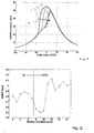
- Fourth, when changing mode between conventional SI engine operation and HCCI engine operation the switch has to be accomplished within one engine cycle. Directly after the mode change the auto-ignition timing may be advanced, whereby it is progressively retarded over a number of subsequent cycles until the combustion has stabilised. This is illustrated in Figure 1, where an arrow A indicates retardation of subsequent cycles C1, C2, C3, C4. The extremely early combustion phasing of the first few HCCI cycles, have an impact on engine load. This is apparent from Figure 2, where the load in Net Mean Effective Pressure (NMEP) is shown for a few engine cycles before, during, and after a mode change. Due to better fuel conversion efficiency, the load in HCCI mode is higher compared to SI mode. A more detailed analysis of this problem can be found in the SAE paper 2003-01-0753.
- Hence an object of the invention is to provide a means for controlling the ignition timing during auto-ignition, which means allows for monitoring of a current combustion and for correction of a subsequent combustion dependent on the outcome of the monitoring process.
- The above problems are solved by a method, an arrangement and a computer readable storage device for controlling homogeneous charge compression ignition combustion, according to
claims - The residual gas fraction may be increased stepwise for every engine cycle, for the first couple of engine cycles after a mode change. This is done by changing the valve timing event and or exhaust manifold gas pressure stepwise for every engine cycle for the first couple of engine cycles after a mode change until the auto ignition timing stabilises and generates the correct combustion phasing.
- The fresh air amount has to be decreased stepwise for every engine cycle, for the first couple of engine cycles after a mode change. This is done by changing the valve timing event and or manifold air pressure step-wise for every engine cycle for the first couple of engine cycles after a mode change until the auto ignition timing stabilises and generates the correct combustion phasing.
- The cycle temperature of a SI engine cycle is higher than the cycle temperature of a HCCI engine cycle. Both the cylinder walls and the residual gas fraction have a higher temperature during a SI engine cycle. The mode switch between SI engine operation and HCCI engine operation occurs within one engine cycle. The first HCCI combustion is therefore triggered by the residual gas fraction of the last SI engine cycle. The auto-ignition timing of the first HCCI engine cycle (IT1) is triggered by the temperature rise due to the residual gas fraction of the last SI engine cycle (R1), the fresh air amount (F1) and the wall temperature (W1). Due to the lower cycle temperature of the first HCCI engine cycle, the temperature of the residual gas fraction (R2) is lower. The cylinder wall temperature (W2) will be lower as more fresh air is admitted into the combustion chamber, and hence the auto-ignition timing (IT2) will be later. To assure the correct auto-ignition timing i.e. combustion phasing for the second HCCI cycle, the residual gas fraction (R2) has to be bigger or the fresh air amount (F2) has to be less. The same trend can be valid for the third, the fourth, etc. HCCI engine cycle until equilibrium in temperature is reached.
- Hence, after a mode change between SI and HCCI engine operation, the residual gas fraction may be increased stepwise until temperature equilibrium is reached and or the fresh air fraction has to be decreased stepwise until temperature equilibrium is reached.
- According to a preferred embodiment the invention relates to a method for operating an internal combustion engine provided with at least one cylinder and operable in compression ignition mode, said engine comprising:
- a fuel supply means, through which fuel is supplied to a combustion chamber, for each cylinder;
- a piston in the engine cylinder whose compression action causes a mixture of air and fuel within the combustion chamber to be ignited during compression ignition mode;
- at least one inlet valve for admitting gas which includes fresh air into said cylinder;
- at least one exhaust valve for exhausting combusted gases from said cylinder;
- a control unit that controls the timing for each of the inlet and exhaust valves and fuel quantity per combustion cycle supplied by each fuel supply means; and
- at least one sensor for measuring an engine operation parameter.
- When switching from spark ignition to compression ignition mode the following steps are performed:
- controlling the exhaust and intake valves to perform a negative valve overlap in order to retain exhaust residual gas,
- determining a current combustion phasing timing,
- correcting the combustion phasing by increasing the retained exhaust residual gas fraction by stepwise control of a combustion related parameter.
- The combustion phasing may be corrected by selecting a value from a matrix dependent on current engine load and speed.
- Alternatively, the combustion phasing may be determined by measuring at least one combustion related engine parameter and comparing the measured combustion phasing with a desired combustion phasing for the current engine load.
- According to a further embodiment the valve timing may be controlled to increase the residual gas fraction. This can be achieved by adjusting the exhaust valve closing (EVC) timing and the intake valve opening (IVO) timing. Alternatively the exhaust valve opening (EVO) timing may be adjusted, either individually or in combination with the EVC and IVO timings.
- According to a further embodiment the exhaust manifold gas pressure may be increased to increase the residual gas fraction. This can be achieved by controlling a valve in the exhaust conduit or select a suitable EVO timing to make use of exhaust pressure pulses in said conduit. These measures may be taken in combination with the valve timing control described above.
- According to a further embodiment the combustion phasing may be corrected by a stepwise decrease of intake air amount, e.g. by valve timing control. This can be achieved by adjusting the exhaust valve closing (EVC) timing and the intake valve opening (IVO) timing. Alternatively the intake valve closing (IVC) timing may be adjusted, either individually or in combination with the EVC and IVO timings.
- According to a further embodiment the intake manifold air pressure may be reduced to decrease the intake air amount. This can be achieved by controlling a throttle in the intake conduit.
- By using the above methods, it is possible to correct the cycle temperature by a stepwise increase of negative valve overlap. The negative valve overlap may be increased by retarding IVO and/or advancing EVC.
- The above method for correcting the combustion phasing may be carried out during a predetermined number of engine cycles after mode change or until compression ignition combustion phasing is stable.
- According to a further preferred embodiment the invention relates to an internal combustion engine provided with at least one cylinder, which engine comprises:
- a fuel supply means, through which fuel is supplied to a combustion chamber, for each cylinder;
- a piston in the engine cylinder whose compression action causes a mixture of air and fuel within the combustion chamber to be ignited;
- at least one inlet valve for admitting gas which includes fresh air into said cylinder;
- at least one exhaust valve for exhausting combusted gases from said cylinder;
- a control unit that controls the timing for each of the inlet and exhaust valves and fuel quantity per combustion cycle supplied by each fuel supply means, and
- at least one sensor for measuring an engine operation parameter.
- When performing a switch between spark ignition and compression ignition mode the exhaust valve is arranged to be closed before top dead center during an exhaust stroke of the piston and the intake valve is arranged to be opened after top dead center during an induction stroke of the piston, in order to achieve a negative overlap and retain residual exhaust gas. A sensor determines a current combustion phasing timing, and the control unit is arranged to adjust intake and exhaust valve timing to increase the negative overlap in steps during number of engine cycles following a mode switch. The size of the step for a subsequent cycle is dependent on the combustion phasing for the current cycle.
- According to a further embodiment the control unit is arranged to adjust intake and exhaust valve timing during a predetermined number of engine cycles after a mode change or until the compression ignition timing is stabilised.
- According to a further preferred embodiment the invention relates to a computer readable storage device having stored therein data representing instructions executable by a computer to implement a mode switch from spark ignition to compression ignition for an internal combustion engine, the engine having a piston disposed in a cylinder to define a combustion chamber, intake valves for admitting fresh air into the cylinder, a fuel supply means for supplying fuel to the combustion chamber, and exhaust valves for discharging exhaust gas resulting from combustion within the cylinder, wherein opening and closing timings of the intake valves and opening and closing timings of the exhaust valves are adjustable. The computer readable storage device comprises:
- instructions for adjusting opening and closing timings of the intake valves and opening and closing timings of the exhaust valves such that the piston reciprocates within the cylinder to perform an exhaust phase, an exhaust gas retaining phase, an intake phase, a compression phase, and an expansion phase;
- instructions for closing the exhaust valve before top dead center during an exhaust stroke of the piston and opening the intake valve after top dead center during an induction stroke of the piston, in order to achieve a negative overlap and retain residual exhaust gas
- instructions for determining a current combustion phasing timing;
- instructions for the control unit to adjust intake and exhaust valve timing to increase the negative overlap in steps during number of engine cycles following a mode switch, where the size of the step for a subsequent cycle is dependent on the combustion phasing for the current cycle.
- According to a further embodiment the computer readable storage device further comprises instructions for correcting the combustion phasing by selecting a value from a matrix dependent on current engine load and speed.
- According to a further embodiment the computer readable storage device further comprises instructions for determining the combustion phasing by measuring at least one combustion related engine parameter, and instructions for comparing the measured combustion phasing with a desired combustion phasing for the current engine load.
- In the following text, the invention will be described in detail with reference to the attached drawings. These drawings are used for illustration only and do not in any way limit the scope of the invention. In the drawings:
- Figure 1
- shows a shows a diagram illustrating cylinder pressure traces for a number of consecutive engine cycles for a prior art engine;
- Figure 2
- shows a diagram illustrating variations in NMEP for a number of engine cycles before, during, and after a mode change;
- Figure 3
- shows a schematic internal combustion engine according to the invention;
- Figure 4
- shows a diagram illustrating the variation of cylinder pressure over crank angle for HCCI- and SI-mode;
- Figure 5
- shows a shows a diagram illustrating cylinder pressure traces for a number of consecutive engine cycles for an engine according to the invention.
- Figure 3 shows a schematic illustration of an internal combustion engine according to the invention. The engine is provided with at least one
cylinder 1 and comprises afuel injector 2, through which fuel is injected into acombustion chamber 3, for each cylinder. A fuelinjection control unit 4 controls fuel injection quantity per combustion cycle injected through each fuel injector. Apiston 5 in the engine cylinder has a compression action that causes a mixture of air and fuel within the combustion chamber to be ignited during HCCI-mode. The cylinder is provided with at least oneinlet valve 6 for admitting gas which includes fresh air into said cylinder and at least oneexhaust valve 7 for exhausting combusted gases from said cylinder. Air is supplied through anintake conduit 9 connected to an intake manifold, while exhaust gas is exhausted through anexhaust conduit 10. During SI-mode, the ignition of the fuel/air mixture is ignited by aspark plug 8. - The control unit receives signals from at least one sensor for measuring engine operation parameters, which sensors include a combustion
chamber pressure sensor 11, an intakemanifold pressure sensor 12 and a λ-probe 13 in the exhaust conduit, as well as temperature sensors forintake air 14,engine coolant 15 andengine oil 16. The control unit controls the intake andexhaust valves valve actuators - Although Figure 3 shows a direct injected (DI) engine, the invention is not limited to DI engines. The number of intake and exhaust valves per cylinder and the number and types of sensors used may also be varied within the scope of the invention. For instance, the physical pressure sensor described may also be a virtual sensor or some other means for indicating combustion timing, or heat release timing. If required, the invention can also be applied to an open loop system receiving no sensor feedback.
- Figure 4 shows a diagram illustrating the variation of cylinder pressure over crank angle for HCCI- and SI-mode. As can be seen from the curves in the diagram, the engine can be operated in homogeneous charge compression ignition (HCCI) combustion mode and in conventional spark ignited (SI) combustion mode. The HCCI combustion has no moving flame front, as opposed to a SI combustion that has a moving flame front. The lack of a flame front reduces temperature and increases the heat release rate hence increases the thermal efficiency of the combustion. An increased dilution ratio for the same compression ratio, in an unthrottled engine, will result in a considerably higher peak pressure after ignition, typically in excess of 40 bar, as opposed to about 20 bar in SI mode. The main difference between the HCCI- and SI modes is that a part of the combustion residuals are captured by operating the engine with a negative valve overlap. The negative valve overlap is achieved by closing the exhaust valve, or valves, before piston top dead center (TDC) and opening the inlet valve, or valves, after piston TDC in the gas exchange phase (GE) of the combustion, as illustrated in Figure 4. During the air intake phase, residuals increase the temperature of the mixture so that the auto ignition temperature is reached before TDC and dilutes the mixture so that the heat release rate decreases to an acceptable level. By controlling the heat release, noise and knocking combustion can be reduced.
- The abbreviations used in the text and/or figures are as follows:
- EVC = Exhaust Valve Closing
- EVO = Exhaust Valve Opening
- IVO = Intake Valve Opening
- IVC = Intake Valve Closing
- SIG = Spark Ignition
- CIG = Compression Ignition
- INJ = Fuel Injection (single or split direct injection, or port injection)
-
- Fuel injection during HCCI mode can be performed as a single port or direct injection INJS, preferably but not necessarily before TDC during the negative valve overlap, or as a split fuel injection by means of a pilot direct fuel injection INJP before TDC during the negative valve overlap and a main direct fuel injection INJM after TDC of the negative valve overlap. The relative quantities of fuel injected during the single, or the pilot and the main injections can be varied and are calculated and controlled by a fuel injection control unit (see Fig. 3). The fuel of the single or the pilot injection INJP will react in the retained residuals, forming radicals, intermediates or combustion products. This reaction can be_exothermic hence heating the residuals, resulting in earlier timing of the auto ignition temperature. A prerequisite for this reaction is the presence of excess oxygen, without which the reaction will stop before it is completed. When the engine is operated in HCCI-mode the control unit must adjust the value of λ to be sufficiently high for all engine operating conditions to ensure this. The total quantity of injected fuel for the pilot and the main injection is substantially constant with respect to the current engine operating conditions, such as engine speed, engine load and efficiency. The quantity of the first injection is selected to be in the range of 0 < INJP < 45% of the total amount of injected fuel.
- Due to the demand for dilution, which controls the rate of heat release, only the part load regime of the engine is used for HCCI combustion mode. The auto ignition timing for HCCI operation can be controlled by the pilot fuel injection and/or the captured amount of residuals and/or the absolute manifold pressure. The latter may be controlled by increasing the pressure of the intake air by means of a compressor or turbocharger.
- When operating the engine according the above method, the residual gas fraction is increased stepwise for every engine cycle, for the first couple of engine cycles after a mode change, while the fresh air amount is decreased stepwise for every engine cycle. This results in an improved combustion stability during a mode change, as illustrated in Figure 5, as the stepwise retardation of the ignition timing as shown in Figure 1 can be reduced or eliminated.
- When operating the engine, engine knocking, low combustion stability and a high noise level has to be avoided. Knocking, which is also a source of noise, is detected by measuring the peak pressure and/or pressure variations caused by a too rapid heat release during the expansion phase. Knocking occurs when the peak pressure exceeds an expected maximum pressure, or when a series of rapid pressure variations occur during the expansion phase. Low combustion stability is indicated by high cycle to cycle variations of the pressure during combustion. Typically, an engine operated in HCCI mode may oscillate between a late phased combustion (low cylinder pressure) and a subsequent early phased combustion (high cylinder pressure).
- A more detailed explanation of HCCI operation under different engine operating conditions can be found in the SAE-paper SAE 2001-01-3610, the entirety of which is hereby incorporated into the description by reference. This SAE-paper discusses the influence of valve timing on HCCI auto-ignition delay and uses a number of valve timing events to identify a HCCI operational window
Claims (18)
- A method for operating an internal combustion engine provided with at least one cylinder and operable in spark ignition and compression ignition modes, said engine comprising:characterized byat least one inlet valve for admitting gas which includes fresh air into said cylinder;at least one exhaust valve for exhausting combusted gases from said cylinder;
that the following steps are performed when switching from spark ignition to compression ignition mode:controlling the exhaust and intake valves to perform a negative valve overlap in order to retain exhaust residual gas,determining a current combustion phasing timing, andcorrecting the combustion phasing by increasing the retained exhaust residual gas fraction by stepwise control of a combustion related parameter. - A method according to claim 1, characterized by correcting the combustion phasing by selecting a value from a matrix dependent on current engine load and speed.
- A method according to claim 1, characterized bydetermining the combustion phasing by measuring at least one combustion related engine parameter,comparing the measured combustion phasing with a desired combustion phasing for the current engine load.
- A method according to claim 3, characterized by controlling the valve timing to increase the residual gas fraction.
- A method according to claim 3 or 4, characterized by increasing exhaust manifold gas pressure to increase the residual gas fraction.
- A method according to claim 3, characterized by correcting the combustion phasing by a stepwise decrease of intake air amount.
- A method according to claim 6, characterized by controlling the valve timing to decrease the intake air amount.
- A method according to claim 6 or 7, characterized by reducing intake manifold air pressure to decrease the intake air amount.
- A method according to claim 4 or 7, characterized by correcting the temperature by a stepwise increase of negative valve overlap.
- A method according to claim 9, characterized by advancing exhaust valve closing timing to increase the negative valve overlap.
- A method according to claim 10, characterized by retarding intake valve opening timing to increase the negative valve overlap.
- A method according to claim 9, characterized by retarding intake valve opening timing to increase the negative valve overlap.
- A method according to claim 1, characterized by correcting the combustion phasing during a predetermined number of engine cycles after mode change or until compression ignition combustion phasing is stable.
- An internal combustion engine provided with at least one cylinder (1) and comprising:characterized in that for performing a switch between spark ignition and compression ignition mode,a fuel supply means, through which fuel is supplied to a combustion chamber, for each cylinder;a piston (5) in the engine cylinder whose compression action causes a mixture of air and fuel within the combustion chamber to be ignited;at least one inlet valve (6) for admitting gas which includes fresh air into said cylinder;at least one exhaust valve (7) for exhausting combusted gases from said cylinder;a control unit (4) that controls the timing for each of the inlet and exhaust valves (6, 7) and fuel quantity per combustion cycle supplied by each fuel supply means (2); andat least one sensor for measuring an engine operation parameter;the exhaust valve is arranged to be closed before top dead center during an exhaust stroke of the piston and the intake valve is arranged to be opened after top dead center during an induction stroke of the piston, in order to achieve a negative overlap and retain residual exhaust gas,a sensor determines a current combustion phasing timing, andthe control unit is arranged to adjust intake and exhaust valve timing to increase the negative overlap in steps during number of engine cycles following a mode switch, where the size of the step for a subsequent cycle is dependent on the combustion phasing for the current cycle.
- A method according to claim 14, characterized in that the control unit is arranged to adjust intake and exhaust valve timing during a predetermined number of engine cycles after mode change or until the compression ignition timing is stabilised
- A computer readable storage device having stored therein data representing instructions executable by a computer to implement a mode switch from spark ignition to compression ignition for an internal combustion engine, the engine having a piston disposed in a cylinder to define a combustion chamber, intake valves for admitting fresh air into the cylinder, a fuel supply means for supplying fuel to the combustion chamber, and exhaust valves for discharging exhaust gas resulting from combustion within the cylinder, wherein opening and closing timings of the intake valves and opening and closing timings of the exhaust valves are adjustable, characterized by the computer readable storage device comprising:instructions for adjusting opening and closing timings of the intake valves and opening and closing timings of the exhaust valves such that the piston reciprocates within the cylinder to perform an exhaust phase, an exhaust gas retaining phase, an intake phase, a compression phase, and an expansion phase;instructions for closing the exhaust valve before top dead center during an exhaust stroke of the piston and opening the intake valve after top dead center during an induction stroke of the piston, in order to achieve a negative overlap and retain residual exhaust gasinstructions for determining a current combustion phasing timing;instructions for the control unit to adjust intake and exhaust valve timing to increase the negative overlap in steps during number of engine cycles following a mode switch, where the size of the step for a subsequent cycle is dependent on the combustion phasing for the current cycle.
- A computer readable storage device according to claim 16, characterized by the computer readable storage device further comprising:instructions for correcting the combustion phasing by selecting a value from a matrix dependent on current engine load and speed.
- A computer readable storage device according to claim 16, characterized by the computer readable storage device further comprisinginstructions for determining the combustion phasing by measuring at least one combustion related engine parameter,instructions for comparing the measured combustion phasing with a desired combustion phasing for the current engine load.
Priority Applications (3)
| Application Number | Priority Date | Filing Date | Title |
|---|---|---|---|
| DE60320972T DE60320972D1 (en) | 2003-07-01 | 2003-07-01 | Apparatus and computer-readable storage medium for controlling homogeneous self-ignited combustion |
| EP03077060A EP1496231B1 (en) | 2003-07-01 | 2003-07-01 | An arrangement and a computer readable storage device for controlling homogeneous charge compression ignition combustion |
| US10/882,599 US7089912B2 (en) | 2003-07-01 | 2004-07-01 | Method, an arrangement, and a computer readable storage device for controlling homogeneous charge compression ignition combustion |
Applications Claiming Priority (1)
| Application Number | Priority Date | Filing Date | Title |
|---|---|---|---|
| EP03077060A EP1496231B1 (en) | 2003-07-01 | 2003-07-01 | An arrangement and a computer readable storage device for controlling homogeneous charge compression ignition combustion |
Publications (2)
| Publication Number | Publication Date |
|---|---|
| EP1496231A1 true EP1496231A1 (en) | 2005-01-12 |
| EP1496231B1 EP1496231B1 (en) | 2008-05-14 |
Family
ID=33442805
Family Applications (1)
| Application Number | Title | Priority Date | Filing Date |
|---|---|---|---|
| EP03077060A Expired - Lifetime EP1496231B1 (en) | 2003-07-01 | 2003-07-01 | An arrangement and a computer readable storage device for controlling homogeneous charge compression ignition combustion |
Country Status (3)
| Country | Link |
|---|---|
| US (1) | US7089912B2 (en) |
| EP (1) | EP1496231B1 (en) |
| DE (1) | DE60320972D1 (en) |
Cited By (7)
| Publication number | Priority date | Publication date | Assignee | Title |
|---|---|---|---|---|
| EP1750000A3 (en) * | 2005-08-05 | 2007-11-14 | Toyota Jidosha Kabushiki Kaisha | Fuel injection control system and method for a compression ignition internal combustion engine |
| WO2008065856A1 (en) * | 2006-11-30 | 2008-06-05 | Kabushiki Kaisha Toyota Jidoshokki | Premixed compression ignition type engine and method of controlling the same |
| DE102007016278A1 (en) * | 2007-04-04 | 2008-10-09 | Bayerische Motoren Werke Aktiengesellschaft | Combustion process for a reciprocating internal combustion engine |
| DE102006043440B4 (en) * | 2006-09-15 | 2009-03-19 | Ford Global Technologies, LLC, Dearborn | A method and apparatus for reducing noise and vibration in a hybrid spark ignition / homogeneous compression ignition internal combustion engine |
| US7680584B2 (en) | 2006-07-27 | 2010-03-16 | Robert Bosch Gmbh | Procedure for the operation of an internal combustion engine |
| DE112005002669B4 (en) * | 2004-10-27 | 2016-02-18 | International Engine Intellectual Property Company, Llc | Air management strategy for a self-ignition in a compression ignition engine |
| CN108490111A (en) * | 2018-05-21 | 2018-09-04 | 沈阳工程学院 | Constant volume tubular type flame propagation measurement device |
Families Citing this family (17)
| Publication number | Priority date | Publication date | Assignee | Title |
|---|---|---|---|---|
| DE10348138B4 (en) * | 2003-10-16 | 2016-09-15 | Daimler Ag | Method for operating an internal combustion engine |
| US20050183693A1 (en) * | 2004-02-25 | 2005-08-25 | Ford Global Technologies Llc | Method and apparatus for controlling operation of dual mode hcci engines |
| JP4462018B2 (en) * | 2004-11-18 | 2010-05-12 | 株式会社デンソー | Engine control system |
| WO2006096425A2 (en) * | 2005-03-03 | 2006-09-14 | General Motors Global Technology Operations, Inc. | Method for transition between controlled auto-ignition and spark ignition modes direct fuel injection engines |
| CN101287897A (en) * | 2005-03-03 | 2008-10-15 | 通用汽车环球科技运作公司 | Load Transient Control Method for Direct Injection Engines with Controlled Auto-Ignition Combustion |
| DE112006000529B4 (en) * | 2005-03-03 | 2016-02-18 | General Motors Global Technology Operations, Inc. | A method of controlling transient loads between lean and stoichiometric combustion modes of direct injection self-ignition combustion engines |
| WO2006096423A2 (en) * | 2005-03-03 | 2006-09-14 | General Motors Global Technology Operations, Inc. | Speed transient control methods for direct-injection engines with controlled auto-ignition combustion |
| US7117830B1 (en) * | 2005-11-23 | 2006-10-10 | Ford Global Technologies, Llc | System and method for direct injection of gaseous fuel into internal combustion engine |
| US7475668B2 (en) * | 2006-01-26 | 2009-01-13 | Deere & Company | Spark ignition to compression ignition transition in an internal combustion engine |
| JP2007297992A (en) * | 2006-05-01 | 2007-11-15 | Toyota Motor Corp | Control device for internal combustion engine |
| US7571707B2 (en) * | 2007-04-19 | 2009-08-11 | Ford Global Technologies, Llc | Engine mode transition utilizing dynamic torque control |
| US7703434B2 (en) * | 2007-06-05 | 2010-04-27 | Gm Global Technology Operations, Inc. | Method and apparatus for controlling ignition timing in a compression-ignition engine operating in an auto-ignition mode |
| FR2933449B1 (en) * | 2008-07-03 | 2010-07-30 | Inst Francais Du Petrole | PROCESS FOR IMPROVING THE VAPORIZATION OF A UTLISE FUEL FOR AN INTERNAL COMBUSTION ENGINE, IN PARTICULAR DIRECT INJECTION, IN PARTICULAR SELF-LIGHTING AND ESPECIALLY DIESEL TYPE |
| US20100288225A1 (en) * | 2009-05-14 | 2010-11-18 | Pfefferle William C | Clean air reciprocating internal combustion engine |
| US9835079B2 (en) * | 2009-06-10 | 2017-12-05 | Alvar Engine Ab | Engine control method |
| US20150285178A1 (en) * | 2014-04-02 | 2015-10-08 | Caterpillar Inc. | Reactivity controlled compression ignition engine and method of combustion phasing control |
| GB2560872B (en) * | 2016-12-23 | 2020-03-18 | Ricardo Uk Ltd | Split cycle engine |
Citations (7)
| Publication number | Priority date | Publication date | Assignee | Title |
|---|---|---|---|---|
| US6082342A (en) * | 1997-03-07 | 2000-07-04 | Institut Francais Du Petrole | Process for controlling self-ignition in a 4-stroke engine |
| EP1085192A2 (en) * | 1999-09-14 | 2001-03-21 | Nissan Motor Co., Ltd. | Compression autoignition gasoline engine |
| EP1164277A2 (en) * | 2000-06-15 | 2001-12-19 | Nissan Motor Company, Limited | Auto-ignition combustion management in internal combustion engine |
| EP1201903A1 (en) * | 2000-10-25 | 2002-05-02 | Ford Global Technologies, Inc. | Method of controlling the combustion process in an internal combustion engine and an engine with means for controlling the engine valves |
| US6390054B1 (en) * | 2000-08-26 | 2002-05-21 | Ford Global Technologies, Inc. | Engine control strategy for a hybrid HCCI engine |
| US20030056736A1 (en) * | 2001-09-06 | 2003-03-27 | Eduard Unger | Method for operating an internal combustion engine |
| EP1310649A1 (en) * | 2000-08-17 | 2003-05-14 | Hitachi, Ltd. | Compression ignition internal combustion engine |
Family Cites Families (6)
| Publication number | Priority date | Publication date | Assignee | Title |
|---|---|---|---|---|
| US5765532A (en) * | 1996-12-27 | 1998-06-16 | Cummins Engine Company, Inc. | Cylinder pressure based air-fuel ratio and engine control |
| SE521783C2 (en) | 1998-10-26 | 2003-12-09 | Volvo Ab | Methods for controlling the combustion process in an internal combustion engine and engine with means for varying the effective compression ratio of the cylinders |
| SE521782C2 (en) | 1998-10-26 | 2003-12-09 | Volvo Ab | Methods of controlling the combustion process in an internal combustion engine and engine with means for controlling the valves of the engine |
| US6644275B2 (en) * | 2001-03-12 | 2003-11-11 | Denso Corporation | Apparatus for controlling engine |
| US6840235B2 (en) * | 2002-09-19 | 2005-01-11 | Nissan Motor Co., Ltd. | Internal exhaust gas recirculation amount estimation system of internal combustion engines |
| JP2004251183A (en) * | 2003-02-19 | 2004-09-09 | Toyota Motor Corp | Control device for internal combustion engine |
-
2003
- 2003-07-01 EP EP03077060A patent/EP1496231B1/en not_active Expired - Lifetime
- 2003-07-01 DE DE60320972T patent/DE60320972D1/en not_active Expired - Lifetime
-
2004
- 2004-07-01 US US10/882,599 patent/US7089912B2/en not_active Expired - Lifetime
Patent Citations (7)
| Publication number | Priority date | Publication date | Assignee | Title |
|---|---|---|---|---|
| US6082342A (en) * | 1997-03-07 | 2000-07-04 | Institut Francais Du Petrole | Process for controlling self-ignition in a 4-stroke engine |
| EP1085192A2 (en) * | 1999-09-14 | 2001-03-21 | Nissan Motor Co., Ltd. | Compression autoignition gasoline engine |
| EP1164277A2 (en) * | 2000-06-15 | 2001-12-19 | Nissan Motor Company, Limited | Auto-ignition combustion management in internal combustion engine |
| EP1310649A1 (en) * | 2000-08-17 | 2003-05-14 | Hitachi, Ltd. | Compression ignition internal combustion engine |
| US6390054B1 (en) * | 2000-08-26 | 2002-05-21 | Ford Global Technologies, Inc. | Engine control strategy for a hybrid HCCI engine |
| EP1201903A1 (en) * | 2000-10-25 | 2002-05-02 | Ford Global Technologies, Inc. | Method of controlling the combustion process in an internal combustion engine and an engine with means for controlling the engine valves |
| US20030056736A1 (en) * | 2001-09-06 | 2003-03-27 | Eduard Unger | Method for operating an internal combustion engine |
Cited By (13)
| Publication number | Priority date | Publication date | Assignee | Title |
|---|---|---|---|---|
| DE112005002669B4 (en) * | 2004-10-27 | 2016-02-18 | International Engine Intellectual Property Company, Llc | Air management strategy for a self-ignition in a compression ignition engine |
| EP1750000A3 (en) * | 2005-08-05 | 2007-11-14 | Toyota Jidosha Kabushiki Kaisha | Fuel injection control system and method for a compression ignition internal combustion engine |
| US7680584B2 (en) | 2006-07-27 | 2010-03-16 | Robert Bosch Gmbh | Procedure for the operation of an internal combustion engine |
| DE102006043440B4 (en) * | 2006-09-15 | 2009-03-19 | Ford Global Technologies, LLC, Dearborn | A method and apparatus for reducing noise and vibration in a hybrid spark ignition / homogeneous compression ignition internal combustion engine |
| KR101032012B1 (en) * | 2006-11-30 | 2011-05-02 | 가부시키가이샤 도요다 지도숏키 | Premixed Compression Ignition Engine and its Control Method |
| US8096279B2 (en) | 2006-11-30 | 2012-01-17 | Kabushiki Kaisha Toyota Jidoshokki | Premixed compression ignition type engine and method of controlling the same |
| CN101595290B (en) * | 2006-11-30 | 2012-07-04 | 株式会社丰田自动织机 | Premixed compression ignition type engine and method of controlling the same |
| DE112007002866B4 (en) * | 2006-11-30 | 2012-12-27 | Kabushiki Kaisha Toyota Jidoshokki | Premix compression ignition type internal combustion engine and method of controlling the same |
| WO2008065856A1 (en) * | 2006-11-30 | 2008-06-05 | Kabushiki Kaisha Toyota Jidoshokki | Premixed compression ignition type engine and method of controlling the same |
| US7874277B2 (en) | 2007-04-04 | 2011-01-25 | Bayerische Motoren Werke Aktiengesellschaft | Combustion method for a reciprocating piston internal combustion engine |
| DE102007016278A1 (en) * | 2007-04-04 | 2008-10-09 | Bayerische Motoren Werke Aktiengesellschaft | Combustion process for a reciprocating internal combustion engine |
| CN108490111A (en) * | 2018-05-21 | 2018-09-04 | 沈阳工程学院 | Constant volume tubular type flame propagation measurement device |
| CN108490111B (en) * | 2018-05-21 | 2023-09-01 | 沈阳工程学院 | Constant volume tube flame spread measuring device |
Also Published As
| Publication number | Publication date |
|---|---|
| US7089912B2 (en) | 2006-08-15 |
| US20050188955A1 (en) | 2005-09-01 |
| DE60320972D1 (en) | 2008-06-26 |
| EP1496231B1 (en) | 2008-05-14 |
Similar Documents
| Publication | Publication Date | Title |
|---|---|---|
| EP1496231B1 (en) | An arrangement and a computer readable storage device for controlling homogeneous charge compression ignition combustion | |
| US7156070B2 (en) | Method for auto-ignition operation and computer readable storage device for use with an internal combustion engine | |
| US7194996B2 (en) | Internal combustion engine and method for auto-ignition operation of said engine | |
| US6994072B2 (en) | Method for mid load operation of auto-ignition combustion | |
| US8165779B2 (en) | Cascade control of HCCI phasing | |
| EP2058499B1 (en) | Apparatus and method for controlling a homogeneous charge compression-ignited internal-combustion engine | |
| AU2004277515B2 (en) | Method and apparatus for pilot fuel introduction and controlling combustion in gaseous-fuelled internal combustion engine | |
| US6609493B2 (en) | System and method for enhanced combustion control in an internal combustion engine | |
| EP1167734B1 (en) | Enhanced multiple injection for auto-ignition in internal combustion engines | |
| US7059281B2 (en) | Four stroke engine auto-ignition combustion | |
| EP1134398A2 (en) | System and method for auto-ignition of gasoline internal combustion engine | |
| EP1559886A2 (en) | Method and apparatus for gaseous fuel introduction and controlling combustion in an internal combustion engine | |
| US20100242901A1 (en) | Control of internal combustion engine | |
| EP2171233A1 (en) | Control of controlled-auto-ignition (cai) combustion process | |
| EP1435442B1 (en) | Internal combustion engine, method for auto-ignition operation and computer readable storage device | |
| EP1435445A1 (en) | Internal combustion engine, method for auto-ignition operation and computer readable storage device | |
| EP1925793A1 (en) | Increased HCCI operation window | |
| JP2018096220A (en) | Control device for internal combustion engine | |
| JP2005098187A (en) | Control device for internal combustion engine | |
| KR20070031409A (en) | Diesel Engine Fueling Strategy by Selective Use of Fuel Supply Map to Extend HCI Combustion Range |
Legal Events
| Date | Code | Title | Description |
|---|---|---|---|
| PUAI | Public reference made under article 153(3) epc to a published international application that has entered the european phase |
Free format text: ORIGINAL CODE: 0009012 |
|
| AK | Designated contracting states |
Kind code of ref document: A1 Designated state(s): AT BE BG CH CY CZ DE DK EE ES FI FR GB GR HU IE IT LI LU MC NL PT RO SE SI SK TR |
|
| AX | Request for extension of the european patent |
Extension state: AL LT LV MK |
|
| 17P | Request for examination filed |
Effective date: 20050201 |
|
| AKX | Designation fees paid |
Designated state(s): DE GB SE |
|
| RAP1 | Party data changed (applicant data changed or rights of an application transferred) |
Owner name: FORD GLOBAL TECHNOLOGIES, LLC. |
|
| 17Q | First examination report despatched |
Effective date: 20060811 |
|
| GRAP | Despatch of communication of intention to grant a patent |
Free format text: ORIGINAL CODE: EPIDOSNIGR1 |
|
| RTI1 | Title (correction) |
Free format text: AN ARRANGEMENT AND A COMPUTER READABLE STORAGE DEVICE FOR CONTROLLING HOMOGENEOUS CHARGE COMPRESSION IGNITION COMBUSTION |
|
| GRAS | Grant fee paid |
Free format text: ORIGINAL CODE: EPIDOSNIGR3 |
|
| GRAA | (expected) grant |
Free format text: ORIGINAL CODE: 0009210 |
|
| AK | Designated contracting states |
Kind code of ref document: B1 Designated state(s): DE GB SE |
|
| REG | Reference to a national code |
Ref country code: GB Ref legal event code: FG4D |
|
| REF | Corresponds to: |
Ref document number: 60320972 Country of ref document: DE Date of ref document: 20080626 Kind code of ref document: P |
|
| REG | Reference to a national code |
Ref country code: SE Ref legal event code: TRGR |
|
| PLBE | No opposition filed within time limit |
Free format text: ORIGINAL CODE: 0009261 |
|
| STAA | Information on the status of an ep patent application or granted ep patent |
Free format text: STATUS: NO OPPOSITION FILED WITHIN TIME LIMIT |
|
| 26N | No opposition filed |
Effective date: 20090217 |
|
| PGFP | Annual fee paid to national office [announced via postgrant information from national office to epo] |
Ref country code: GB Payment date: 20120625 Year of fee payment: 10 |
|
| GBPC | Gb: european patent ceased through non-payment of renewal fee |
Effective date: 20130701 |
|
| PG25 | Lapsed in a contracting state [announced via postgrant information from national office to epo] |
Ref country code: GB Free format text: LAPSE BECAUSE OF NON-PAYMENT OF DUE FEES Effective date: 20130701 |
|
| PGFP | Annual fee paid to national office [announced via postgrant information from national office to epo] |
Ref country code: DE Payment date: 20200615 Year of fee payment: 18 |
|
| PGFP | Annual fee paid to national office [announced via postgrant information from national office to epo] |
Ref country code: SE Payment date: 20200709 Year of fee payment: 18 |
|
| REG | Reference to a national code |
Ref country code: DE Ref legal event code: R119 Ref document number: 60320972 Country of ref document: DE |
|
| PG25 | Lapsed in a contracting state [announced via postgrant information from national office to epo] |
Ref country code: DE Free format text: LAPSE BECAUSE OF NON-PAYMENT OF DUE FEES Effective date: 20220201 |
|
| PG25 | Lapsed in a contracting state [announced via postgrant information from national office to epo] |
Ref country code: SE Free format text: LAPSE BECAUSE OF NON-PAYMENT OF DUE FEES Effective date: 20210702 |