EP1495896A2 - Layout structure of a driving device for a vehicle - Google Patents
Layout structure of a driving device for a vehicle Download PDFInfo
- Publication number
- EP1495896A2 EP1495896A2 EP04014901A EP04014901A EP1495896A2 EP 1495896 A2 EP1495896 A2 EP 1495896A2 EP 04014901 A EP04014901 A EP 04014901A EP 04014901 A EP04014901 A EP 04014901A EP 1495896 A2 EP1495896 A2 EP 1495896A2
- Authority
- EP
- European Patent Office
- Prior art keywords
- vehicle
- driving device
- engine
- layout structure
- disposed
- Prior art date
- Legal status (The legal status is an assumption and is not a legal conclusion. Google has not performed a legal analysis and makes no representation as to the accuracy of the status listed.)
- Granted
Links
Images


Classifications
-
- B—PERFORMING OPERATIONS; TRANSPORTING
- B60—VEHICLES IN GENERAL
- B60H—ARRANGEMENTS OF HEATING, COOLING, VENTILATING OR OTHER AIR-TREATING DEVICES SPECIALLY ADAPTED FOR PASSENGER OR GOODS SPACES OF VEHICLES
- B60H1/00—Heating, cooling or ventilating [HVAC] devices
- B60H1/24—Devices purely for ventilating or where the heating or cooling is irrelevant
- B60H1/241—Devices purely for ventilating or where the heating or cooling is irrelevant characterised by the location of ventilation devices in the vehicle
- B60H1/242—Devices purely for ventilating or where the heating or cooling is irrelevant characterised by the location of ventilation devices in the vehicle located in the front area
-
- B—PERFORMING OPERATIONS; TRANSPORTING
- B60—VEHICLES IN GENERAL
- B60H—ARRANGEMENTS OF HEATING, COOLING, VENTILATING OR OTHER AIR-TREATING DEVICES SPECIALLY ADAPTED FOR PASSENGER OR GOODS SPACES OF VEHICLES
- B60H1/00—Heating, cooling or ventilating [HVAC] devices
- B60H1/00007—Combined heating, ventilating, or cooling devices
- B60H1/00207—Combined heating, ventilating, or cooling devices characterised by the position of the HVAC devices with respect to the passenger compartment
-
- B—PERFORMING OPERATIONS; TRANSPORTING
- B60—VEHICLES IN GENERAL
- B60H—ARRANGEMENTS OF HEATING, COOLING, VENTILATING OR OTHER AIR-TREATING DEVICES SPECIALLY ADAPTED FOR PASSENGER OR GOODS SPACES OF VEHICLES
- B60H1/00—Heating, cooling or ventilating [HVAC] devices
- B60H1/00271—HVAC devices specially adapted for particular vehicle parts or components and being connected to the vehicle HVAC unit
-
- B—PERFORMING OPERATIONS; TRANSPORTING
- B60—VEHICLES IN GENERAL
- B60H—ARRANGEMENTS OF HEATING, COOLING, VENTILATING OR OTHER AIR-TREATING DEVICES SPECIALLY ADAPTED FOR PASSENGER OR GOODS SPACES OF VEHICLES
- B60H1/00—Heating, cooling or ventilating [HVAC] devices
- B60H1/00357—Air-conditioning arrangements specially adapted for particular vehicles
-
- B—PERFORMING OPERATIONS; TRANSPORTING
- B60—VEHICLES IN GENERAL
- B60H—ARRANGEMENTS OF HEATING, COOLING, VENTILATING OR OTHER AIR-TREATING DEVICES SPECIALLY ADAPTED FOR PASSENGER OR GOODS SPACES OF VEHICLES
- B60H1/00—Heating, cooling or ventilating [HVAC] devices
- B60H1/24—Devices purely for ventilating or where the heating or cooling is irrelevant
- B60H1/247—Disposition of several air-diffusers in a vehicle for ventilation-air circulation in a vehicle cabin
-
- B—PERFORMING OPERATIONS; TRANSPORTING
- B60—VEHICLES IN GENERAL
- B60K—ARRANGEMENT OR MOUNTING OF PROPULSION UNITS OR OF TRANSMISSIONS IN VEHICLES; ARRANGEMENT OR MOUNTING OF PLURAL DIVERSE PRIME-MOVERS IN VEHICLES; AUXILIARY DRIVES FOR VEHICLES; INSTRUMENTATION OR DASHBOARDS FOR VEHICLES; ARRANGEMENTS IN CONNECTION WITH COOLING, AIR INTAKE, GAS EXHAUST OR FUEL SUPPLY OF PROPULSION UNITS IN VEHICLES
- B60K15/00—Arrangement in connection with fuel supply of combustion engines or other fuel consuming energy converters, e.g. fuel cells; Mounting or construction of fuel tanks
- B60K15/03—Fuel tanks
- B60K15/063—Arrangement of tanks
- B60K15/067—Mounting of tanks
-
- B—PERFORMING OPERATIONS; TRANSPORTING
- B60—VEHICLES IN GENERAL
- B60K—ARRANGEMENT OR MOUNTING OF PROPULSION UNITS OR OF TRANSMISSIONS IN VEHICLES; ARRANGEMENT OR MOUNTING OF PLURAL DIVERSE PRIME-MOVERS IN VEHICLES; AUXILIARY DRIVES FOR VEHICLES; INSTRUMENTATION OR DASHBOARDS FOR VEHICLES; ARRANGEMENTS IN CONNECTION WITH COOLING, AIR INTAKE, GAS EXHAUST OR FUEL SUPPLY OF PROPULSION UNITS IN VEHICLES
- B60K15/00—Arrangement in connection with fuel supply of combustion engines or other fuel consuming energy converters, e.g. fuel cells; Mounting or construction of fuel tanks
- B60K15/03—Fuel tanks
- B60K15/073—Tank construction specially adapted to the vehicle
-
- B—PERFORMING OPERATIONS; TRANSPORTING
- B60—VEHICLES IN GENERAL
- B60K—ARRANGEMENT OR MOUNTING OF PROPULSION UNITS OR OF TRANSMISSIONS IN VEHICLES; ARRANGEMENT OR MOUNTING OF PLURAL DIVERSE PRIME-MOVERS IN VEHICLES; AUXILIARY DRIVES FOR VEHICLES; INSTRUMENTATION OR DASHBOARDS FOR VEHICLES; ARRANGEMENTS IN CONNECTION WITH COOLING, AIR INTAKE, GAS EXHAUST OR FUEL SUPPLY OF PROPULSION UNITS IN VEHICLES
- B60K5/00—Arrangement or mounting of internal-combustion or jet-propulsion units
- B60K5/02—Arrangement or mounting of internal-combustion or jet-propulsion units with the engine main axis, e.g. crankshaft axis, substantially in or parallel to the longitudinal centre line of the vehicle
-
- B—PERFORMING OPERATIONS; TRANSPORTING
- B62—LAND VEHICLES FOR TRAVELLING OTHERWISE THAN ON RAILS
- B62D—MOTOR VEHICLES; TRAILERS
- B62D25/00—Superstructure or monocoque structure sub-units; Parts or details thereof not otherwise provided for
- B62D25/08—Front or rear portions
- B62D25/081—Cowls
-
- B—PERFORMING OPERATIONS; TRANSPORTING
- B62—LAND VEHICLES FOR TRAVELLING OTHERWISE THAN ON RAILS
- B62D—MOTOR VEHICLES; TRAILERS
- B62D25/00—Superstructure or monocoque structure sub-units; Parts or details thereof not otherwise provided for
- B62D25/08—Front or rear portions
- B62D25/082—Engine compartments
Abstract
Description
- The present invention relates to a layout structure of a driving device for a vehicle in which a passenger compartment is separated by a dash panel from an engine room.
- The following structure is known as an example of the above-described layout structure of a driving device for a vehicle (see Japanese Laid-Open Patent Publication No. 6-239147). Namely, as shown in FIG. 29, that is a conventional structure of a FR (front-engine rear-drive) type, in which there are provided a
passenger compartment 191 which is separated by adash panel 192 from anengine room 193 and located in front of thepassenger compartment 191 and rear wheels (not shown) are driven by anengine 194 disposed in a longitudinal direction of the vehicle in theengine room 193. Herein,reference numerals - This conventional structure has a problem that since the
engine 194 having its heavy weight is disposed in theengine room 193 which is located forward away from a center of the vehicle, its yaw inertia moment is relatively large. - Then, in order to improve maneuverability of the vehicle by reducing the yaw inertia moment, there may be an idea of use of, for example, a compact structure of air conditioning unit (see Japanese Laid-Open Patent Publication No. 2001-105833) or a film-dumper type of air conditioning unit (see Japanese Laid-Open Patent Publication No. 10-324141).
- These air conditioning units enable the engine located forward to be moved back to some extent toward the center of the vehicle, so that the maneuverability of the vehicle can be improved to certain degree due to a reduced yaw inertia moment.
- In order to reduce the yaw inertia moment further to improve the maneuverability of the vehicle more, it would be necessary to make the engine more compact or to provide a further moved-back engine layout. However, there is a limit in compactness of the engine, thus it may be desired to move the engine back further so that the engine could be located as near the center of the vehicle as possible.
- Meanwhile, there has been proposed an air conditioning device for a vehicle, in which an auto air conditioner is disposed behind a dash panel in a front portion of the vehicle, whereas a rear cooler unit is disposed in a back portion of the vehicle (see Japanese Laid-Open Patent Publication No. 5-193337). However, since it still falls within a conventional air conditioning device, this device could not provide the above-described further moved-back engine layout.
- Further, there has been proposed a structure, in which a cowl box is provided above a dash lower panel so as to extend substantially in a width direction of a vehicle and an air conditioning unit is disposed behind the above-described dash lower panel (see Japanese Laid-Open Patent Publication No. 8-58431). However, since this is just a structure showing conventional cowl box and air conditioning unit, this structure could not provide the above-described further moved-back engine layout either.
- The present invention has been devised in view of the above-mentioned problems, and an object of the present invention is to provide a layout structure of a driving device for a vehicle that can improve maneuverability and stability of the vehicle and dynamic performance of the vehicle by reducing a yaw inertia moment.
- This object is solved according to the invention by a layout structure according to
claim 1. Preferred embodiments of the invention are subject of the dependent claims. - In order to achieve the above-described object, the present invention provides a layout structure of a driving device for a vehicle, in which a passenger compartment is separated by a dash panel from an engine room, comprising a cowl portion for supporting a front end of a windshield that is disposed above the dash panel so as to extend substantially in a width direction of the vehicle, an instrument panel member that is located backward away from the cowl portion so as to extend substantially in the width direction of the vehicle above the dash panel, and a recess portion that is formed in such manner that an intermediate portion, preferably substantially a central portion of the dash panel in the width direction of the vehicle is recessed backward from the cowl portion to the instrument panel member, wherein the driving device for the vehicle is disposed in the recess portion such that the driving device is located in front of and close to or in proximity of or adjacent to the instrument panel member.
- Accordingly, there is provided a layout structure of a driving device for a vehicle that can improve maneuverability and stability of the vehicle and dynamic performance of the vehicle by reducing a yaw inertia moment due to a moved-back layout of the driving device and increase rigidity of a vehicle body due to a large-scale instrument panel member, in which a recess portion is formed in such manner that part of a dash panel is recessed backward from a cowl portion to the instrument panel member located backward away from the cowl portion and the driving device is disposed in the recess portion.
- In fact, according to the above-described structure, since the recess portion is formed in such manner that part of the dash panel is recessed backward from the cowl portion to the instrument panel member located backward away from the cowl portion and the driving device is disposed in the recess portion, the above-described moved-back layout of the driving device having its heavy weight can be achieved, thereby improving maneuverability and stability of the vehicle and dynamic performance of the vehicle due to a reduced yaw inertia moment and also increasing rigidity of the vehicle body due to the large-scale instrument panel member.
- In a preferred embodiment of the present invention, the driving device comprises an engine disposed substantially in a longitudinal direction of the vehicle and an ISG unit connected subsequently to a rear portion of the engine. Herein, the ISG unit (Integrated Starter Generator Unit) functions as both a starter and a generator, and is referred to as ISG hereinafter.
- According to the above-described structure, although providing the ISG unit behind the engine may increase a length of the driving device in the vehicle longitudinal direction, it can be achieved to lay out the heavy article, namely the driving device, close to the center of the vehicle regardless of the increased length, thereby improving maneuverability and stability of the vehicle and dynamic performance of the vehicle due to the reduced yaw inertia moment.
- In another preferred embodiment of the present invention, a transmission is disposed behind the ISG unit so as to be connected subsequently to the ISG unit in a tunnel portion of a floor panel.
- According to the above-described structure, the transmission can be also laid out close to the center in the vehicle longitudinal direction.
- In another preferred embodiment of the present invention, an upper end of the engine is disposed so as to be located in a higher position than that of a sitting face of a passenger seat disposed on the floor panel.
- According to the above-described structure, the moved-back layout of the heavy articles of the engine and the ISG unit can be achieved, providing a low vehicle-height by locating the upper end of the engine in the higher position than that of the sitting face of the seat.
- In another preferred embodiment of the present invention, the engine and the ISG unit are located in a position where these are at least partly overlapped with a passenger sitting on the passenger seat in the longitudinal direction of the vehicle.
- According to the above-described structure, since the engine and the ISG unit are at least partly overlapped with the passenger sitting on the passenger seat in the longitudinal direction of the vehicle, the length of the vehicle can be short, maintaining an enough space for the passenger in a passenger compartment, and the moved-back layout of the engine can be achieved.
- In another preferred embodiment of the present invention, an exhaust system of the engine is disposed so as to extend by way of a front portion of one side of the engine.
- According to the above-described structure, since the engine exhaust system, especially an exhaust manifold, extends in front of the engine once, a proper layout of the exhaust system can be achieved by making use of a space effectively. Namely, in the case where the moved-back layout of the heavy article is aimed by providing the engine extending in the vehicle longitudinal direction in the recess portion of the dash panel, there may remain only a relatively small layout space for the exhaust system. However, the proper layout of the exhaust system can be achieved by making use of the space effectively, by configuring the exhaust manifold with a relatively large volume for the purpose of a high exhaust efficient so as to extend in front of the engine once.
- In another preferred embodiment of the present invention, a vehicle body panel disposed between the cowl portion and the upper end of the dash panel is formed so as to be detachable.
- According to the above-described structure, the function of services can be improved by the detachable structure of the vehicle body panel.
- In another preferred embodiment of the present invention, a service hole is formed at a portion between the front end supporting portion for the windshield and the instrument panel member which corresponds to the recess portion, and the vehicle body panel is disposed detachably to at least partly cover the service hole.
- According to the above-described structure, the function of services can be improved by the detachable structure of the vehicle body panel.
- In another preferred embodiment of the present invention, the vehicle body panel is configured so as to provide an enough space where a cylinder head cover of the engine is removable while it is to be detached.
- According to the above-described structure, since the cylinder head cover of the engine is able to be removed, the function of services can be maintained, achieving the moved-back layout of the engine.
- In another preferred embodiment of the present invention, an air conditioning unit for air-conditioning the passenger compartment is disposed substantially behind the passenger compartment.
- According to the above-described structure, since the air conditioning unit is disposed behind the passenger compartment, namely in the back portion of the vehicle, the moved-back layout of the driving device can be achieved surely.
- In another preferred embodiment of the present invention, a load compartment is formed behind the air conditioning unit.
- According to the above-described structure, the layout of the air conditioning unit can be compatible with forming the load compartment.
- In another preferred embodiment of the present invention, a heat exchanger is interposed between a front end of the driving device and an axle of a front wheel.
- According to the above-described structure, since the heavy articles of the driving device and the heat exchanger can be moved back toward the center of the vehicle, the yaw inertia moment can be reduced further, thereby improving maneuverability and stability of the vehicle and dynamic performance of the vehicle.
- In another preferred embodiment of the present invention, the heat exchanger is mounted on a suspension cross member supporting a suspension for the front wheel.
- According to the above-described structure, a support of the heat exchanger can be provided effectively by making use of an existing member, namely the suspension cross member. Further, since rigidity of the suspension cross member is high, a high-rigidity support of the heat exchanger can be maintained.
- In another preferred embodiment of the present invention, a front portion of the driving device is mounted on the suspension cross member.
- According to the above-described structure, a pitching (a front/rear end's movement in a vertical direction) of the driving device can be prevented by mounting the front end of the driving device on the suspension cross member.
- In another preferred embodiment of the present invention, the suspension cross member comprises a main portion thereof with a substantially U-shaped figure when viewed from above and a transverse member integral or unitary with the main portion and extending substantially in the width direction of the vehicle, and the front portion of the driving device is mounted on the transverse member.
- According to the above-described structure, mounting of the front end of the driving device can be provided effectively by making use of the transverse member (existing member) located in the best position.
- In another preferred embodiment of the present invention, the driving device is mounted on the suspension cross member at one or more points, preferably at three different points.
- According to the above-described structure, the pitching of the driving device can be prevented more efficiently.
- In another preferred embodiment of the present invention, an air cleaner is disposed above the heat exchanger, a recess portion is formed on a lower face of the air cleaner at a portion which corresponds to the heat exchanger, and an upper portion of the heat exchanger is located in the recess portion of the air cleaner.
- According to the above-described structure, the air cleaner with an enough volume can be provided, reducing the vehicle height properly. Further, the air cleaner as a heavy article can also be moved back as much as possible, by providing the above-described recess portion.
- In another preferred embodiment of the present invention, a storage portion for a small load is formed in front of the heat exchanger and/or the air cleaner.
- According to the above-described structure, the small load can be kept in the storage portion, thereby improving facility.
- The invention further related to a vehicle having a layout structure of a driving device according to the invention or a preferred embodiment thereof.
- Other features, aspects, and advantages of the present invention will become apparent from the following description of the invention which refers to the accompanying drawings. It should be understood that even though embodiments are separately described, single features thereof may be combined to additional embodiments.
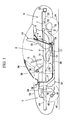
- FIG. 1 is a side view for showing a layout structure of a driving device for a vehicle according to the first embodiment of the present invention.
- FIG. 2 is a plan view of FIG. 1.
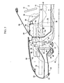
- FIG. 3 is an enlarged side view of a main part of FIG. 1.
- FIG. 4 is an enlarged plan view of a main part of FIG. 2.
- FIG. 5 is an explanatory diagram for showing a positional relationship between a passenger on a seat and the driving device.
- FIG. 6 is an enlarged view of a main part of FIG. 3.
- FIG. 7 is an exploded plan view of a main part of FIG. 6.
- FIG. 8 is an enlarged view of a main part of another embodiment of a cowl box.
- FIG. 9 is a schematic sectional view of an ISG unit.
- FIG. 10 is a schematic side view for showing a layout structure of a driving device for a vehicle according to the second embodiment of the present invention.
- FIG. 11 is an explanatory diagram for showing a relationship between a passenger and a power train.
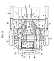
- FIG. 12 is a schematic plan view of FIG. 10.
- FIG. 13 is a sectional view of a tunnel portion.
- FIG. 14 is an enlarged side view for showing a structure of a left side of a vehicle front.
- FIG. 15 is an enlarged side view for showing a structure of a right side of a vehicle front.
- FIG. 16 is an enlarged plan view of a main part of FIG. 12.
- FIG. 17 is a side view for showing a supporting structure of a lower part of a radiator.
- FIG. 18 is an elevation view for showing a supporting structure of an upper part of the radiator.
- FIG. 19 is a side view for showing a layout relationship between the radiator and an air cleaner.
- FIG. 20 is a side view for showing another embodiment of a supporting structure of a trunk pan.
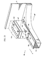
- FIG. 21 is a perspective view for showing a mounting structure of a battery.
- FIG. 22 is a plan view for showing a mounting structure of the driving device.
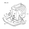
- FIG. 23 is a perspective view of a main part showing the mounting structure of the driving device.
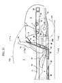
- FIG. 24 is an enlarged side view of a main part of FIG. 10.
- FIG. 25 is a bottom plan view of FIG. 24.
- FIG. 26 is a plan view of a main part of FIG. 24.
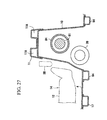
- FIG. 27 is a sectional view of a main part, taken on line B-B of FIG. 24.
- FIG. 28 is a sectional view of the main part, taken on line C-C of FIG. 24.
- FIG. 29 is a plan view for showing a conventional layout structure of a driving device for a vehicle.
-
- Hereinafter, preferred embodiments of the present invention will be described with reference to the accompanying drawings.
- A first preferred embodiment of the present invention will be described in detail referring to FIGS. 1 through 9. The figures show a layout structure of a driving device for a vehicle. In a side view, FIG. 1 and a plan view, FIG. 2, an engine room or
compartment 1 is separated by a dash lower panel 3 (dash panel) from apassenger compartment 2 in a longitudinal direction of the vehicle. - A
floor panel 4 is subsequently connected to a lower end portion of the dashlower panel 3 to extend backward in a substantially horizontal direction. Abulkhead 5 is provided so as to rise up slantingly from a rear portion of thefloor panel 4, at a back face of an upper end portion of which there is provided arear cowl portion 6 extending substantially in a width direction of the vehicle. Herein, therear bulkhead 5 is a panel member which separates thepassenger compartment 2 from a rear part compartment. - Further, a
rear floor 7 is provided to extend backward from an intermediate portion, preferably a middle portion of thebulkhead 5 substantially in a vertical direction of the vehicle. Anair conditioning unit 8 for air-conditioning thepassenger compartment 2 is provided near therear cowl portion 6 on therear floor 7, and a load compartment 9 (so-called trunk room) is formed behind theair conditioning unit 8 and/or therear cowl portion 6. - At a central portion of the
floor panel 4, there is provided atunnel portion 10 which protrudes in thepassenger compartment 2 and extends substantially in the vehicle longitudinal direction. A tunnel member 11 (so-called high-mount-backbone frame) is fixed on an upper portion of thetunnel portion 10. Thetunnel member 11 is connected to the dashlower panel 3 at its front end and to thebulkhead 5 at its rear end. A closed cross section extending in the vehicle longitudinal direction is formed by thetunnel member 11 and thetunnel portion 10. Thus, thetunnel member 11 provides a structure which can improve rigidity of vehicle floor and body. - There are provided a pair of left and
right seats floor panel 4 with the above-describedtunnel portion 10 andtunnel member 11 between them, which include seat cushions 12, 12 and seat backs 13, 13 respectively. In this embodiment, theright seat 14 corresponding to asteering wheel 15 is a driver's seat, and theleft seat 14 is a passenger's seat. - In the above-described
engine room 1, there are provided a pair of left and right front side frames 16, 16, rear ends of which are connected with the dashlower panel 3 and which extend forward substantially in the vehicle longitudinal direction from the dashlower panel 3. A kick-up portion of each rear portion of the front side frames 16, 16 is provided along the dashlower panel 3, and there are provided a pair of left and right floor frames 17, 17 which are coupled to respective lower ends of the kick-up portions and extend substantially in the vehicle longitudinal direction. - A
front cross member 18 extending substantially in the vehicle width direction is interposed between front portions of the front side frames 16, 16 (see FIG. 4), andrear cross members floor panel 4. - A pair of left and right rear side frames 20, 20 are provided so as to extend under the
rear floor 7 from back faces of therear cross members rear cross members rear bumper reinforcement 23 extending substantially in the vehicle width direction is provided at rear portions of the rear side frames 20, 20. - There are provided a pair of
side sills floor panel 4, which extend substantially in the vehicle longitudinal direction preferably substantially in parallel to the floor frames 17, 17. Each of theside sills - The
side sills hinge pillars hinge pillars - FIG. 3 is an enlarged side view of a main part of FIG. 1, and FIG. 4 is an enlarged plan view of a main part of FIG. 2. As shown in FIG. 3, there is provided a
cowl portion 27 for supporting a front end of awindshield 26 that is disposed above the dashlower panel 3 so as to extend substantially in the vehicle direction. In this embodiment, thecowl portion 27 is comprised of a cowl upper 28 and acowl box 29. - There is provided an
instrument panel member 30 preferably with a substantially closed cross section that is located backward away from thecowl portion 27 so as to extend substantially in the vehicle width direction above the dashlower panel 3. Theinstrument panel member 30 is connected with rear portions of thehinge pillars - Further, as shown in FIG. 4, there is provided a
recess portion 3a that is formed in such manner that an intermediate portion, preferably a central portion of the dashlower panel 3 in the vehicle width direction is recessed backward from thecowl portion 27 to theinstrument panel member 30. Herein, a pair ofextension portions tunnel member 11 fixed on thetunnel portion 10, which extend forward substantially along side faces of therecess portion 3a of the dashlower panel 3 to a base face (non-recessed face). - Further, a pair of instrument-
panel connecting members instrument panel member 30 with thetunnel member 11 to improve the vehicle rigidity. - As shown in FIGS. 3 and 4, an
engine 32 is at least partly disposed in therecess portion 3a such that it is located in front of and close to or in proximity of or adjacent to theinstrument panel member 30. In other words, by providing therecess portion 3a, it is possible to position theengine 32 more backwards toward thepassenger compartment 2 and closer to theinstrument panel 30. Theengine 32 is at least partly located below thecowl portion 27 and/or thewindshield 26. Theengine 32 is at least partly disposed in the vehicle longitudinal direction and comprises an ISG unit 33 (Integrated Starter Generator Unit, which functions as both a starter and a generator) connected subsequently to a rear portion of theengine 32. Preferably, more than about 1/3, more preferably more than about half, most preferably more than about 2/3, of a vehicle driving device (preferably comprising theengine 32 and the ISG unit 33) are located more rearward or behind of a front portion of the dashlower panel 3 in the longitudinal vehicle direction. Accordingly, the portion of the vehicle driving device located more rearward than the front portion of the dashlower panel 3 preferably is located in therecess portion 3a of the dashlower panel 3. Further, atransmission 34 is disposed behind theISG unit 33 so as to be connected subsequently to theISG unit 33 in thetunnel portion 10 of thefloor panel 4. - Herein, the
ISG unit 33 includes astator 33S and arotor 33R disposed in acase 33C, in which therotor 33R is rotated by a drive axle 80 (propeller shaft) to produce electric power (see FIG. 9). - As shown in FIG. 5, an upper end of the
engine 32 is disposed so as to be located in a higher position than that of a sitting face of thepassenger seat 14 disposed on thefloor panel 4, and theengine 32, theISG unit 33 and thetransmission 34 are located in a position where these are at least partly overlapped with a passenger A sitting on thepassenger seat 14 in the vehicle longitudinal direction. Accordingly, a height and a length of the entire vehicle are reduced as much as possible so as to provide a compact vehicle. - As shown in FIGS. 3 an 4, an exhaust system is coupled to an exhaust side of a cylinder head of the
engine 32, which comprises anexhaust manifold 35 extending forward at one side of theengine 32 from the cylinder head. - Further, a
first exhaust pipe 36 is provided to extend from a gathering portion of theexhaust manifold 35 located at the one side of theengine 32 in the substantially vertical direction, and a catalyst 37 (so-called adjacent catalyst) is disposed in thefirst exhaust pipe 36. - Further, a
second exhaust pipe 38 located downstream of thefirst exhaust pipe 36 is disposed in thetunnel portion 10, and acatalyst 39, asilencer 40 and abifurcate exhaust pipe 41 are coupled to downstream portions of the second exhaust pipe 38 (see FIG. 2). - Namely, the exhaust system of the
engine 32 is comprised of the above-describedparts 35 though 41, which is disposed so as to extend by way of a front portion of the one side of theengine 32. Accordingly, even if a layout space for the gathering portion of the exhaust system becomes small due to the moved-back layout of theengine 32, the disposition of theexhaust manifold 35 and its gathering portion can be achieved surely by making use of this space effectively. - Meanwhile,
front wheels suspension arms suspension arms suspension cross member 44. Thefront wheels steering rack 45 and left-and-right tie rods - A cooling
unit 48 is supported on thesuspension cross member 44 through abracket 47, and a condenser for air conditioning, so-calledcooler condenser 49 is disposed in front of the coolingunit 48. - There is provided a
bonnet 50 covering an upper portion of theengine room 1, and afront grille 52 having anopening 51 for a travelling air intake is formed in front of and/or below thebonnet 50. Theopening 51 and a front face of the coolingunit 48 are coupled by aduct 53. - Meanwhile, as shown in FIGS. 3 and 4, an
air cleaner 54 is disposed above theduct 53 and thecooling unit 48 in theengine room 1. Anintake pipe 55 is attached at a portion upstream of theair cleaner 54, and anintake pipe 56 and anintake manifold 57 are attached to a downstream portion of theair cleaner 54. Accordingly, an air which has been filtered by an element of the air cleaner 54 (see FIG. 3) is supplied into intake ports formed at the cylinder head of theengine 32 through theintake pipe 56 and theintake manifold 57. - FIG. 6 is an enlarged side view of a main part of FIG. 3, and a vehicle body panel disposed between the
cowl portion 27 and an upper end of the dashlower panel 3 is formed so as to be detachable. In this embodiment, the cowl upper 28 constituting a part of thecowl portion 27 is formed so as to be detachable. - Namely, as shown in FIGS. 6 and 7,
nuts 60...60 are fixed by welding at plural portions at a lower face of a front portion of thecowl box 29 which corresponds to abent portion 28a of the cowl upper 28 which is located at a side of thecowl box 29. By puttingbolts 61...61 into the nuts 60...60 from above of the cowl upper 28 and fastening them, the cowl upper 28 as the vehicle body panel is attached to thecowl box 29. When a maintenance service is conducted, thebonnet 50 is opened and then thebolts 61...61 are unfastened and removed. Accordingly, the cowl upper 28 is detached from thecowl box 29 and the dashlower panel 3. - The front portion of the cowl upper 28 is located forward with respect to an upper-end
bent portion 3b of the dashlower panel 3, and a sealingmember 63 for sealing the lower face of thebonnet 50 is attached at an upper end of front portion of the cowl upper 28 so that a gap between areinforcement 62 and the front portion of the cowl upper 28 can be sealed up. - Further, a
service hole 64 is formed between thecowl box 29 functioning as the front supporting portion forwindshield 26 and an upper-endbent portion 3c of therecess portion 3a which is located adjacent to theinstrument panel member 30 in such manner that it is located at a portion corresponding to therecess portion 3a. And, there is provided aservice hole cover 65 disposed as a vehicle body panel which detachably at least partly covers theservice hole 64. - In this embodiment, nuts 66..., 67... are fixed preferably by welding at plural portions at a lower face of the
cowl box 29 and a lower face of the upper-endbent portion 3c of therecess portion 3a. By puttingbolts 68..., 69... into the nuts 66..., 67... and fastening them from above theservice hole cover 65, theservice hole cover 65 is to be attached to thecowl box 29 and the upper-endbent portion 3c of therecess portion 3a. When a maintenance service is conducted, theservice hole cover 65 is detached from an opening edge of theservice hole 64 by unfastening thebolts 68..., 69.... - Further, a sealing rubber is interposed between the
service hole cover 65 and an opening edge or edge portion of theservice hole 64 as a sealing member. There is also provided an enough space for enabling a cylinder head cover 71 (see FIG. 6) of theengine 32 to be removed when the cowl upper 28 and theservice hole cover 65 as preferred vehicle body panels are detached as shown in FIG. 7. - Herein, although it is made of an aluminium material in FIG. 6, the
cowl box 29 may be configured by attaching anouter member 29A made of a steel panel and aninner member 29B made of a steel panel as shown in FIG. 8.Reference numerals - As described above, the present embodiment provides the layout structure of the driving device for the vehicle, in which the
passenger compartment 2 is separated by the dashlower panel 3 from theengine room 1, comprising thecowl portion 27 for supporting the front end of thewindshield 26 that is disposed above the dashlower panel 3 so as to extend substantially in the vehicle width direction, theinstrument panel member 30 that is located backward away from thecowl portion 27 so as to extend substantially in the vehicle width direction above the dashlower panel 3, and therecess portion 3a that is formed in such manner that the central portion of the dashlower panel 3 in the vehicle width direction is recessed backward from thecowl portion 27 to theinstrument panel member 30, wherein the driving device (engine 32) is disposed in therecess portion 3a such that the driving device (engine 32) is located in front of and close to or in proximity of theinstrument panel member 30. - According to the above-described structure, since the
recess portion 3a is formed in such manner that part of the dashlower panel 3 is recessed backward from thecowl portion 27 to theinstrument panel member 30 located backward away from thecowl portion 27 and the driving device (see the engine 32) is disposed in therecess portion 3a, the moved-back layout of the driving device having a heavy weight can be achieved, thereby improving maneuverability and stability of the vehicle and dynamic performance of the vehicle due to the reduced yaw inertia moment and also increasing rigidity of the vehicle body due to the large-scaleinstrument panel member 30. - Further, the driving device comprises the
engine 32 preferably disposed substantially in the vehicle longitudinal direction and theISG unit 33 connected subsequently to the rear portion of theengine 32. According to this structure, although providing theISG unit 33 behind theengine 32 may increase a length of the driving device in the vehicle longitudinal direction, it can be achieved to lay out the heavy article close to the center of the vehicle regardless of the increased length, thereby improving maneuverability and stability of the vehicle and dynamic performance of the vehicle due to the reduced yaw inertia moment. - Further, the
transmission 34 is disposed behind theengine 32 and/or theISG unit 33 so as to be connected subsequently to theISG unit 33 in thetunnel portion 10 of thefloor panel 4. According to this structure, thetransmission 34 can be also laid out closer or close to the center in the vehicle longitudinal direction. - In addition, the upper end of the
engine 32 is disposed so as to be located in a higher position than that of the sitting face of thepassenger seat 14 disposed on thefloor panel 4. According to this structure, the moved-back layout of the heavy articles or the mass center of theengine 32 and theISG unit 33 can be achieved, providing a low vehicle-height by locating the upper end of theengine 32 in the higher position than that of the sitting face of theseat 14. - Further, the
engine 32, theISG unit 33 and thetransmission 34 are located in a position where these are at least partly overlapped with the passenger A (see FIG. 5) sitting on thepassenger seat 14 in the vehicle longitudinal direction. According to this structure, since theengine 32, theISG unit 33 and thetransmission 34 are at least partly overlapped with the passenger A sitting on thepassenger seat 14 in the vehicle longitudinal direction, the length of the vehicle can be short, maintaining an enough space for the passenger in the passenger compartment, and the moved-back layout of theengine 32 can be achieved. - Further, the vehicle body panel (see the cowl upper panel 28) disposed between the
cowl portion 27 and the upper end of the dashlower panel 3 is formed so as to be detachable. According to this structure, the function of services can be improved by the detachable structure of at least part of the vehicle body panel. - In addition, the
service hole 64 is formed at a portion between the front end supporting portion (see the cowl box 29) for thewindshield 26 and theinstrument panel member 30 which at least partly corresponds to therecess portion 3a, and the vehicle body panel (see the service hole cover 65) is disposed detachably to at least partly cover theservice hole 64. According to this structure, the function of services can be improved by the detachable structure of the vehicle body panel. - Furthermore, the vehicle body panel (see the cowl upper 28 and/or service hole cover 65) is configured so as to provide an enough space where the
cylinder head cover 71 of theengine 32 is removable while it is detached. According to this structure, since thecylinder head cover 71 of theengine 32 is able to be removed, the function of services can be maintained, achieving the moved-back layout of theengine 32. - Further, as shown in FIG. 4, the exhaust system (see the
exhaust manifold 35 particularly) of theengine 32 is disposed so as to extend by way of the front portion of the one side of theengine 32. According to this structure, since the engine exhaust system, especially theexhaust manifold 35, at least partly extends in front of the engine once, a proper layout of the exhaust system can be achieved by making use of a space effectively. Namely, in the case where the moved-back layout of the heavy article is aimed by providing theengine 32 at least partly extending in the vehicle longitudinal direction in therecess portion 3a of the dashlower panel 3, there may remain only a relatively small layout space for the exhaust system. However, the proper layout of the exhaust system can be achieved by making use of a space effectively, by configuring theexhaust manifold 35 with a relatively large volume for the purpose of a high exhaust efficient so as to at least partly extend in front of theengine 32 once. - Further, the
air conditioning unit 8 for air-conditioning thepassenger compartment 2 is disposed preferably behind thepassenger compartment 2. According to this structure, since theair conditioning unit 8 is preferably disposed behind thepassenger compartment 2, namely in the back portion of the vehicle, the moved-back layout of the driving device can be achieved surely. - Also, the
load compartment 9 is formed preferably behind theair conditioning unit 8. According to this structure, the layout of theair conditioning unit 8 can be compatible with forming theload compartment 9. - With respect to the correspondence in structure between the present invention and the above-described embodiment, the dash panel is preferably embodied by the dash
lower panel 3, the vehicle body panel is preferably embodied by the cowl upper 28 (specifically, cowl upper panel) and/or theservice hole cover 65, and the front end supporting portion for the windshield is preferably embodied by thecowl box 29. However, the invention is not limited to this embodiment. - A second preferred embodiment of the present invention will be described. This embodiment comprises a structure in which a heat exchanger is interposed between a front end of the driving device and an axle of the front wheel. This structure is shown in FIGS. 10 through 19, and hereinafter it will be described in detail referring to these drawings.
- Herein, the similar or same structure as the above-described first embodiment is illustrated in the same way, having the same reference numerals, in respective figures which correspond to those of the first embodiment, whose detailed descriptions will be omitted hereinafter. (FIGS. 10, 11, 12, 14 and 16 correspond respectively to FIG. 1, 5, 2, 3 and 4)
- As shown in FIGS. 14 and 15, the cooling unit 48 (the unit including a radiator and a fan) is supported on the
suspension cross member 44 through thebracket 47, and the air conditioning condenser, namely the so-calledcooler condenser 49 is located in front of the coolingunit 48. - Herein, a lower portion of a
radiator 150 of the coolingunit 48 is supported as shown in a side view of FIG. 17. Namely, thebracket 47 with a substantially U-shaped view in the side view is attached to thesuspension cross member 44 through connectingmeans 151 such as bolts and nuts, and a lower tank of theradiator 150 is mounted on an upper face of thebracket 47 through a mount resilient member orrubber 152. - Meanwhile, an upper end of the
radiator 150 is supported as shown in an elevation view of FIG. 18. Namely, anupper bracket 154 with a substantially S- or Z-shaped view in the elevation view is attached to thefront side frame 16 through connectingmeans 153 such as bolts and nuts, and a upper tank of theradiator 150 is supported at a lower portion of an inner-side projection of theupper bracket 154 through a mount resilient member orrubber 155. Herein, theradiator 150 is disposed, as shown in FIGS. 14 and 15, between the front end of theengine 32 and an axle of thefront wheel 42, namely within a wheel base. - Although FIG. 18 illustrates only one part of supporting structure of the
radiator 150, the other part of theradiator 150 is also supported in substantially the same way as that shown in FIG. 18. Further, in FIGS. 17 and 18, arrows F, R, IN and OUT denote respectively forward, backward, inside and outside directions of the vehicle. - Meanwhile, as shown in FIG. 14, there is provided a
bonnet 156 covering the upper portion of the engine room orcompartment 1, and afront grille 158 having anopening 157 for a travelling air intake is formed in front of and below thebonnet 156. Theopening 157 and the front face of the coolingunit 48 are coupled by an air duct 159 (radiator cooling air intake duct). - As shown in FIGS. 14 and 16, an
air cleaner 160 is disposed above theair duct 159 and thecooling unit 48 in theengine room 1. An intake pipe 161 (so-called fresh air duct) is attached at a portion upstream of theair cleaner 160, and anair intake hose 162 and anintake manifold 163 are attached to a portion downstream of theair cleaner 160. Accordingly, an air which has been filtered by anair cleaner element 164 of the air cleaner 160 (see FIG. 14) is supplied into intake ports formed at the cylinder head of theengine 32 through theair intake hose 162 and theintake manifold 163. - A
recess portion 160a is formed, as shown in FIG. 19, at a portion of a lower face of theair cleaner 160 disposed above theradiator 150 as a heat exchanger which corresponds to the upper tank of theradiator 150. The upper tank of theradiator 150 is at least partly located in therecess portion 160a, and thus an enough volume of theair cleaner 160 can be maintained, reducing the vehicle height as much as possible. - Herein, the
air cleaner 160 includes an aircleaner case 160b, an aircleaner cover 160c, and the air cleaner element 164 (so-called filter) in theair cleaner case 160b, and the above-describedrecess portion 160a is formed at a side of the aircleaner cover 160. - Also, as shown in FIG. 19, a rear-end
upper portion 159a of theair duct 159 and an attachingpiece 49a of thecooler condenser 49 are jointly fixed to the upper tank of theradiator 150 through a rubber member GU by one or more attachingmember 95 such as bolts. - Further, an
insulator 97 for protecting from a heat is attached over the lower face of theair cleaner case 160b of theair cleaner 160 with agap 96 so as to at least partly cover a mostly entire area of the lower face. - Meanwhile, as shown in FIGS. 14, 15 and 16, a
front trunk box 98 as a storage portion for a small load is provided in front of theradiator 150 and theair cleaner 160. - Namely, as shown in the plan view of FIG. 16, there is provided a substantially box-shaped
trunk pan 99 with a bottom by making use of a space enclosed by a pair of front side frames 16, 16, ashroud member 177 and the front cross member 18 (see FIGS. 14 and 15). Thetrunk pan 99 is fixed to the front side frames 16, 16, and the above-describedfront trunk box 98 is fixed to thetrunk pan 99. - The
front trunk box 98 preferably is of a substantially box shape with a bottom, whose upper portion is open. It also has a flange portion extending outwardly at its upper opening edge which is formed integrally or unitarily therewith. - Meanwhile, a
lid member 101 for substantially opening or closing the upper-end opening of thefront trunk box 98 is attached to a lower face of thebonnet 156 through a bellows orextensible member 100. Accordingly, the upper-end opening of thefront trunk box 98 is made open when thebonnet 156 is opened, while it is made closed when thebonnet 156 is closed. - Herein, the
trunk pan 99 may be configured, as shown in FIG. 20, in such manner that at least one, preferably plural portions of thetrunk pan 99 in the vehicle width direction are connected with thefront cross member 18 through one ormore brackets - As shown in FIGS. 10, 12 and 16, there are provided one or more, preferably a pair of
batteries engine 32 in front of the general face of the dash lower panel 3 (just in front of thepanel 3 in this embodiment). - These
batteries ISG unit 33, which are disposed at a joint portion with the dash lower panel on the a pair of front side frames 16, 16 in this embodiment. Herein, eachbattery 165 is disposed such that its front end is located in front of theengine 32 in order to prevent theengine 32 from moving back by having thebattery 165 receive an impact load occurring during a vehicle head-on collision. - As shown in FIG. 16, the above-described
extension portions tunnel member 11 are connected with portions of the dashlower panel 3 which correspond to the location of the battery disposition, so that the collision impact load can be dispersed to the vehicle body. - Further, as shown in FIGS. 12 and 16, the above-described
cooling unit 48 is disposed between thebatteries engine room 1 in such manner that it is at least partly overlapped with thebatteries - Further, heavy articles such as the driving device including the
engine 32 and theISG unit 33, and auxiliary parts of thebatteries radiator 150 are all disposed, as shown in FIGS. 12 and 16, within the wheel base in order to reduce yaw inertia moments thereof. - The above-described
battery 165 is installed as shown in FIG. 21. Namely, it has abattery case 167 which is made of synthetic resin and includes aflange portion 166 integral with a lower portion thereof. And, abattery tray 168 preferably made of steel is interposed between aupper frame 16a of thefront side frame 16 and the bottom of thebattery 165. Then, thebattery 165 in thebattery case 167 is fixed at thefront side frame 16 by inserting one ormore bolts 169... from above of theflange portion 166 into corresponding nuts which has been fixed to a lower face of theupper frame 16a preferably by welding in advance, and fastening them. - Herein, the upper of the
battery 165 is covered with abattery cover 170 which should be attached to thebattery case 167. - Although FIG. 21 illustrates the instalment structure of just one
battery 165, theother battery 165 is also installed on the otherfront side frame 16 in the similar or same way as that shown in FIG. 21. - Herein, in FIGS. 10 through 21, other reference numerals denote parts respectively as follows: a
rear wheel 171; aroof 172 for selectively opening or closing an upper of thepassenger compartment 2; aninstrument panel 173; abumper reinforcement 174 attached to the front end of thefront side frame 16 through a connectingmember 175; anapron reinforcement 176; theshroud member 177; afront header 178; afront pillar 179; and atransverse member 180 of thesuspension cross member 44. - As shown in FIGS 22 and 23, the above-described
suspension cross member 44 comprises amain portion 44A thereof with a substantially U-shaped figure when viewed from above and thetransverse member 180 integral or unitary with themain portion 44A and extending substantially in the width direction of the vehicle, and a front portion of theengine 32 as the driving device, specifically a front portion of a cylinder block is mounted on thetransverse member 180 through an engine front-mount bracket 103 and an engine mount resilient member orrubber 104. - Also, the both sides of the cylinder block are mounted on at least partly overlapped portions of the
transverse member 180 and the suspension crossmain portion 44A through engine-side mount brackets rubbers - Namely, the front portion of the cylinder block of the
engine 32 is mounted on thesuspension cross member 44, and theengine 32 is mounted at one or more, e.g. three different points as shown in FIGS. 22 and 23. - Meanwhile, an output from the
transmission 34 is transferred to therear wheels propeller shaft 81, a reardifferential device 82 and left-and right rear-wheel axles - The above-described rear
differential device 82 is a differential device for driving the rear-wheel axles propeller shaft 81. - Further, a
fuel tank 85 is disposed at least partly below thetrunk room 9 as a load compartment between the above-describedrear bulkhead 5 and/or the rear-wheel axle 83 as shown in FIGS. 24, 25, 26 and 28. In other words, the reardifferential device 82 for driving the rear-wheel axles fuel tank 85, and thus thefuel tank 85 is prevented from being struck by the reardifferential device 82 during the vehicle head-on collision. Further, the above-describedair conditioning unit 8 is located (preferably on therear floor 7 behind the rear bulkhead 5) substantially above thefuel tank 85. - The
fuel tank 85 is provided, as shown in FIG. 28, with arecess portion 85a at its portion which corresponds to the disposition position of thesilencer 40 and thetorque tube PPF 84, and thefuel tank 85 is formed so as to have a substantially L-shaped entire view in the elevation view. - Further, there is provided tank mount straps 86, 86 for mounting (hanging and retaining) the
fuel tank 85 at the tank'smount portions insulator 87 for preventing a heat damage from the exhaust system is interposed between themount portions gap 88 between thetank 85 and theinsulator 87 preferably substantially covering the substantially entire area of the lower face of thefuel tank 85. - At or in the
recess portion 85a on the side of thefuel tank 85, part of theexhaust pipes silencer 40 and thefuel tank 85 are located within the wheel base, and thus the yaw inertia moment is further reduced. Thesilencer 40 is supported on therear side frame 20 through one ormore mount members - Each
mount member 89 includes asilencer mount bracket 90 fixed at the side of thesilencer 40, alower bracket 92 connecting thesilencer mount bracket 90 with a mount resilient member orrubber 91, and anupper bracket 93 connecting therear side frame 20 with themount rubber 91. Further, in order to prevent thesilencer 40 from moving forward to a position in front of the reardifferential device 82 during a vehicle rear collision, thesilencer 40 and the reardifferential device 82 are disposed in such manner that these are at least partly offset from each other in the vehicle width direction, as shown in FIGS. 25 and 26. - Meanwhile, the
exhaust pipes floor panel 4 and below therear floor 7 as shown in FIGS. 24, 25 and 26. Thepassenger seat 14 is placed on thefloor panel 4 in thepassenger compartment 2 as described above. And, as shown in FIGS. 24 and 27, the above-describedcatalyst 39 interposed between theexhaust pipes seat 14, specifically in thetunnel portion 10 to protect the passenger on theseat 14 from the heat damage. - Herein,
reference numerals floor panel 4, and SB denotes a seat buckle. Further, as shown in FIG. 25, eachrear wheel 171 is suspended independently by a multi-link type of rear suspension RS, and the rear suspension RS is supported on the sub-frame SF. - As described above, the present embodiment shows the structure that the driving device (specifically, the engine 32) is disposed in the
recess portion 3a of the dashlower panel 3 as shown in FIG. 16, and at least part of the heat exchanger (see the radiator 150), as shown in FIG. 14, is disposed between the front end of the driving device and the axle of thefront wheel 42. - According to this structure, since the driving device (specifically, the engine 32) as the heavy article is disposed in the
recess portion 3a of the dashlower panel 3 and the heat exchanger (see radiator 150) is disposed between the front end of the driving device and the axle of thefront wheel 42, namely within the wheel base, the heavy articles of the driving device and the heat exchanger can be moved back toward the center of the vehicle. As a result, the yaw inertia moment can be reduced, thereby improving maneuverability and stability of the vehicle and dynamic performance of the vehicle. - Further, there is provided the suspension (see suspension arm 43) suspending the
front wheel 42, and the heat exchanger (see radiator 150) is mounted on thesuspension cross member 44 supporting the suspension as shown in FIG. 17. - According to this structure, the support of the heat exchanger can be provided effectively by making use of the existing member (see suspension cross member 44). Further, since the rigidity of the
suspension cross member 44 is high, the high-rigidity support of the heat exchanger (see radiator 150) can be maintained. - Further, the
air cleaner 160 is disposed substantially above the heat exchanger (see radiator 150) as shown in FIG. 19, therecess portion 160a is formed on the lower face of theair cleaner 160 at the portion which corresponds to the heat exchanger, and the upper portion (see upper tank) of the heat exchanger (see radiator 150) is located in therecess portion 160a. - According to this structure, the
air cleaner 160 with an enough volume can be provided, reducing the vehicle height properly. Further, theair cleaner 160 as a heavy article can also be moved back as much as possible, by providing the above-describedrecess portion 160a. - In addition, the front portion of the driving device (see engine 32) is mounted on the above-described
suspension cross member 44. According to this structure, a pitching (a front/rear end's movement in the vertical direction) of the driving device (see engine 32) can be prevented by mounting the front end of the driving device (see engine 32) on thesuspension cross member 44. - Further, the
suspension cross member 44 comprises, as shown in FIG. 23, themain portion 44A with the substantially U-shaped figure when viewed from above and thetransverse member 180 integral with themain portion 44A and extending substantially in the width direction of the vehicle, and the front portion of the driving device (see engine 32) is mounted on thetransverse member 180. According to this structure, mounting of the front end of the driving device (see engine 32) can be provided effectively by making use of the transverse member 180 (existing member) located in the best position. - Further, the driving device (see engine 32) is mounted on the
suspension cross member 44 preferably at three different points. According to this structure, the pitching of the driving device (see engine 32) can be prevented more efficiently. - In addition, the storage portion (see front trunk box 98) for a small load is formed in front of the heat exchanger (see radiator 150) and/or the
air cleaner 160. According to this structure, the small load can be kept in the storage portion (see front trunk box 98), thereby improving facility. - Further, there is provided the
air conditioning unit 8 for air-conditioning thepassenger compartment 2, and theair conditioning unit 8 is disposed preferably behind thepassenger compartment 2. According to this structure, since theair conditioning unit 8 preferably is disposed in the back portion of the vehicle, the further moved-back layout of the driving device (seeengine 32 in particular) can be achieved without the layout of the air conditioning unit in the front portion of the vehicle. As a result, the yaw inertia moment can be reduced further, thereby improving further the maneuverability and stability of the vehicle and the dynamic performance of the vehicle. - Further, the
load compartment 9 is formed preferably behind theair conditioning unit 8. According to this structure, the layout of theair conditioning unit 8 can be compatible with forming theload compartment 9. - With respect to the correspondence in structure between the present invention and the above-described embodiment, the dash panel preferably is embodied by the dash
lower panel 3, the driving device preferably is embodied by the engine or theengine 32 and theISG unit 33, the heat exchanger (auxiliary part) preferably is embodied by theradiator 150, the suspension preferably is embodied by thesuspension arm 43, the storage for the small load preferably is embodied by thefront trunk box 98. However, the invention is not limited to this embodiment.
Claims (18)
- A layout structure of a driving device for a vehicle, in which a passenger compartment (2) is separated by a dash panel (3) from an engine room (1), comprising:wherein the driving device (32; 33) for the vehicle is disposed in said recess portion (3a) such that the driving device (32; 33) is located in front of and close to said instrument panel member (30).a cowl portion (27) for supporting a front end of a windshield (26) that is disposed above the dash panel (3) so as to extend substantially in a width direction of the vehicle;an instrument panel member (30) that is located backward away from said cowl portion (27) so as to extend substantially in the width direction of the vehicle above the dash panel (3); anda recess portion (3a) that is formed in such manner that an intermediate portion, preferably substantially a central portion, of the dash panel (3) in the width direction of the vehicle is recessed backward from said cowl portion (27) to said instrument panel member (30),
- The layout structure of a driving device for a vehicle of claim 1, wherein said driving device (32; 33) comprises an engine (32) disposed substantially in a longitudinal direction of the vehicle and an ISG unit (33) connected subsequently to a rear portion of the engine (32).
- The layout structure of a driving device for a vehicle of claim 2, wherein a transmission (34) is disposed behind said ISG unit (33) so as to be connected subsequently to said ISG unit (33) in a tunnel portion (10) of a floor panel (4).
- The layout structure of a driving device for a vehicle of claim 2 or 3, wherein an upper end of said engine (32) is disposed so as to be located in a higher position than that of a sitting face of a passenger seat (14) disposed on the floor panel (4).
- The layout structure of a driving device for a vehicle of claim 2, 3 or 4, wherein said engine (32) and ISG (33) unit are located in a position where these are at least partly overlapped with a passenger sitting on a passenger seat (14) in the longitudinal direction of the vehicle.
- The layout structure of a driving device for a vehicle of one of the preceding claims 2 to 5, wherein an exhaust system (35) of the engine (32) is disposed so as to extend by way of a front portion of one side of said engine (32).
- The layout structure of a driving device for a vehicle of one of the preceding claims, wherein a vehicle body panel (65) disposed between said cowl portion (27) and an upper end of said dash panel (3) is formed so as to be detachable.
- The layout structure of a driving device for a vehicle of claim 7, wherein a service hole (64) is formed at a portion between the front end supporting portion for the windshield (26) and said instrument panel member (30) which corresponds to said recess portion (3a), and said vehicle body panel (65) is disposed detachably to at least partly cover said service hole (64).
- The layout structure of a driving device for a vehicle of claim 7 or 8, wherein said vehicle body panel (65) is configured so as to provide an enough space where a cylinder head cover (71) of the engine (32) is removable while it is to be detached.
- The layout structure of a driving device for a vehicle of one of the preceding claims, wherein an air conditioning unit (8) for air-conditioning the passenger compartment (2) is disposed substantially behind the passenger compartment (2).
- The layout structure of a driving device for a vehicle of claim 10, wherein a load compartment (9) is formed behind said air conditioning unit (8).
- The layout structure of a driving device for a vehicle of one of the preceding claims, wherein a heat exchanger (150) is interposed between a front end of said driving device and an axle of a front wheel (42).
- The layout structure of a driving device for a vehicle of claim 12, wherein said heat exchanger (150) is mounted on a suspension cross member (44) supporting a suspension (43) for said front wheel (42).
- The layout structure of a driving device for a vehicle of claim 13, wherein a front portion of said driving device is mounted on said suspension cross member (44).
- The layout structure of a driving device for a vehicle of claim 13 or 14, wherein said suspension cross member (44) comprises a main portion (44A) thereof with a substantially U-shaped figure when viewed from above and a transverse member (180) integral or unitary with the main portion (44A) and extending substantially in the width direction of the vehicle, and said front portion of the driving device is mounted on said transverse member (180).
- The layout structure of a driving device for a vehicle of claim 13, 14 or 15, wherein said driving device (32; 33) is mounted on said suspension cross member (44) at one or more points, preferably at three different points.
- The layout structure of a driving device for a vehicle of one of the preceding claims in combination with claim 12, wherein an air cleaner (160) is disposed above said heat exchanger (150), a recess portion (160a) is formed on a lower face of said air cleaner (160) at a portion which corresponds to said heat exchanger (150), and an upper portion of said heat exchanger (150) is located in said recess portion (160a) of the air cleaner (160).
- The layout structure of a driving device for a vehicle of one of the preceding claims in combination with claim 12 or 17, wherein a storage portion (98) for a small load is formed in front of said heat exchanger (150) and/or said air cleaner (160).
Applications Claiming Priority (4)
| Application Number | Priority Date | Filing Date | Title |
|---|---|---|---|
| JP2003192915A JP4363096B2 (en) | 2003-07-07 | 2003-07-07 | Arrangement structure of vehicle drive device |
| JP2003192915 | 2003-07-07 | ||
| JP2003271902 | 2003-07-08 | ||
| JP2003271902A JP4363106B2 (en) | 2003-07-08 | 2003-07-08 | Auxiliary equipment arrangement structure in vehicle engine room |
Publications (3)
| Publication Number | Publication Date |
|---|---|
| EP1495896A2 true EP1495896A2 (en) | 2005-01-12 |
| EP1495896A3 EP1495896A3 (en) | 2005-06-29 |
| EP1495896B1 EP1495896B1 (en) | 2011-06-15 |
Family
ID=33455600
Family Applications (1)
| Application Number | Title | Priority Date | Filing Date |
|---|---|---|---|
| EP04014901A Expired - Fee Related EP1495896B1 (en) | 2003-07-07 | 2004-06-24 | Layout structure of a driving device for a vehicle |
Country Status (2)
| Country | Link |
|---|---|
| US (1) | US7185725B2 (en) |
| EP (1) | EP1495896B1 (en) |
Cited By (6)
| Publication number | Priority date | Publication date | Assignee | Title |
|---|---|---|---|---|
| EP1707475A2 (en) | 2005-03-31 | 2006-10-04 | Mazda Motor Corporation | Arrangement of engine-associated vehicle components |
| US7556110B2 (en) * | 2005-09-22 | 2009-07-07 | Honda Motor Co., Ltd. | Vehicle mounted with electric storage apparatus |
| US20110284298A1 (en) * | 2009-02-24 | 2011-11-24 | Toyota Jidosha Kabushiki Kaisha | Vehicle front portion structure |
| US8544583B2 (en) | 2010-06-03 | 2013-10-01 | Toyota Jidosha Kabushiki Kaisha | Cooling airflow intake structure |
| DE102011121515B4 (en) * | 2010-12-20 | 2016-06-30 | Mazda Motor Corp. | Battery arrangement structure of a vehicle and method for arranging a battery |
| DE102011121517B4 (en) | 2010-12-27 | 2019-01-31 | Mazda Motor Corporation | A wiring harness arrangement structure of a vehicle and a method of arranging a wiring harness |
Families Citing this family (22)
| Publication number | Priority date | Publication date | Assignee | Title |
|---|---|---|---|---|
| JP4872586B2 (en) * | 2005-11-10 | 2012-02-08 | 日産自動車株式会社 | Car body front structure and connecting member |
| DE102007019407A1 (en) * | 2006-04-25 | 2007-11-08 | Behr America, Inc., Webberville | Molded housing for a vehicle air conditioning module has a molded plastic shell with an integrated cover and hinge molded at an open position with a recess for the position of a fastening screw to cover the heater core |
| US7819220B2 (en) * | 2006-07-28 | 2010-10-26 | Polaris Industries Inc. | Side-by-side ATV |
| US8827028B2 (en) * | 2006-07-28 | 2014-09-09 | Polaris Industries Inc. | Side-by-side ATV |
| US20090313904A1 (en) * | 2009-02-04 | 2009-12-24 | Andrew Kerr | Mechanical access door for passenger bus |
| US8943797B2 (en) | 2010-01-15 | 2015-02-03 | GM Global Technology Operations LLC | Cylinder head with symmetric intake and exhaust passages |
| US8528510B2 (en) * | 2010-01-15 | 2013-09-10 | GM Global Technology Operations LLC | Intake manifold |
| US9103305B2 (en) * | 2010-01-15 | 2015-08-11 | GM Global Technology Operations LLC | Internal combustion engine |
| US8714295B2 (en) * | 2010-01-15 | 2014-05-06 | GM Global Technology Operations LLC | Internal combustion engine and vehicle packaging for same |
| DE102010018481A1 (en) * | 2010-04-28 | 2011-11-03 | Gm Global Technology Operations Llc (N.D.Ges.D. Staates Delaware) | Floor structure of a motor vehicle body |
| US8746719B2 (en) | 2010-08-03 | 2014-06-10 | Polaris Industries Inc. | Side-by-side vehicle |
| US8613335B2 (en) | 2010-08-03 | 2013-12-24 | Polaris Industries Inc. | Side-by-side vehicle |
| JP5742967B2 (en) | 2013-02-20 | 2015-07-01 | トヨタ自動車株式会社 | Electric car |
| JP6060864B2 (en) * | 2013-09-18 | 2017-01-18 | マツダ株式会社 | Storage device arrangement structure |
| US20160169171A1 (en) * | 2014-12-15 | 2016-06-16 | Ford Global Technologies, Llc. | Modular intake manifold |
| AU2016265556B2 (en) | 2015-05-15 | 2019-05-02 | Polaris Industries Inc. | Utility vehicle |
| USD787985S1 (en) | 2015-06-24 | 2017-05-30 | Polaris Industries Inc. | All-terrain vehicle |
| US9649928B2 (en) | 2015-06-25 | 2017-05-16 | Polaris Industries Inc. | All-terrain vehicle |
| US9884647B2 (en) | 2015-12-10 | 2018-02-06 | Polaris Industries Inc. | Utility vehicle |
| JP6922763B2 (en) * | 2018-01-30 | 2021-08-18 | トヨタ自動車株式会社 | Vehicle undercarriage |
| US10946736B2 (en) | 2018-06-05 | 2021-03-16 | Polaris Industries Inc. | All-terrain vehicle |
| US11505143B2 (en) * | 2019-02-27 | 2022-11-22 | Ford Global Technologies, Llc | Supercapacitor mounting assemblies and vehicle mounting locations |
Citations (11)
| Publication number | Priority date | Publication date | Assignee | Title |
|---|---|---|---|---|
| DE295848C (en) * | ||||
| US1934385A (en) * | 1928-06-18 | 1933-11-07 | Joseph B Strauss | Vehicle |
| US2612964A (en) * | 1949-02-17 | 1952-10-07 | Bristol Aeroplane Co Ltd | Chassis frame for road vehicles |
| US2771750A (en) * | 1954-04-12 | 1956-11-27 | Houdaille Industries Inc | Package air conditioning unit for automotive vehicle |
| US2867996A (en) * | 1955-09-01 | 1959-01-13 | George P Bullard | Cooling means for vehicle motors |
| US2989854A (en) * | 1960-03-28 | 1961-06-27 | Gen Motors Corp | Vehicle refrigeration |
| DE3707684A1 (en) * | 1986-03-14 | 1987-09-17 | American Motors Corp | MODULE CONSTRUCTION FOR VEHICLES AND METHOD FOR THEIR PRODUCTION |
| US4723810A (en) * | 1984-06-18 | 1988-02-09 | Mazda Motor Corporation | Underbody structure for vehicle |
| JPH0939837A (en) * | 1995-07-27 | 1997-02-10 | Toyota Auto Body Co Ltd | Dash panel structure of vehicle |
| US6332330B1 (en) * | 1999-09-10 | 2001-12-25 | Valeo Climatisation | Device for motor-vehicle heating and/or air conditioning with improved blower |
| EP1245422A2 (en) * | 2001-03-26 | 2002-10-02 | Visteon Global Technologies, Inc. | Regenerative deceleration for a hybrid drive system |
Family Cites Families (16)
| Publication number | Priority date | Publication date | Assignee | Title |
|---|---|---|---|---|
| US2172831A (en) * | 1938-05-03 | 1939-09-12 | Carlson Philip | Truck body |
| US2817557A (en) * | 1950-01-25 | 1957-12-24 | Chrysler Corp | Unitary body and frame structure for automobiles |
| US3827525A (en) * | 1972-05-24 | 1974-08-06 | Gen Motors Corp | Energy absorbing construction for front-engined motor vehicles |
| AT354863B (en) * | 1975-06-13 | 1980-02-11 | List Hans | MOTOR VEHICLE WITH A SOUND INSULATING CAPSULE FOR THE ENGINE OR. THE ENGINE-GEAR UNIT |
| JPS56161814U (en) | 1980-05-06 | 1981-12-02 | ||
| US4988144A (en) * | 1990-01-16 | 1991-01-29 | General Motors Corporation | Plenum and wiper module removable for engine service |
| JP3144094B2 (en) | 1991-11-13 | 2001-03-07 | 株式会社デンソー | Vehicle air conditioner |
| US5327988A (en) * | 1992-09-22 | 1994-07-12 | Hme, Inc. | Truck having cab with full access engine enclosure |
| JPH06239147A (en) | 1993-02-12 | 1994-08-30 | Mazda Motor Corp | Front side structure of automobile |
| US5511842A (en) * | 1993-10-06 | 1996-04-30 | Dillon; John A. | Security vehicle system |
| JP3596554B2 (en) * | 1994-08-18 | 2004-12-02 | 本田技研工業株式会社 | Instrument panel mounting structure |
| DE19654370C8 (en) | 1996-12-24 | 2013-03-28 | JK Patentportfolio GmbH & Co. Echo KG | Heating system for vehicles |
| JP3744121B2 (en) | 1997-05-27 | 2006-02-08 | 株式会社デンソー | Air conditioner for vehicles |
| JP3977556B2 (en) | 1999-10-14 | 2007-09-19 | カルソニックカンセイ株式会社 | Air conditioning unit for vehicles |
| DE10054008B4 (en) | 2000-11-01 | 2004-07-08 | Daimlerchrysler Ag | Automobile seat |
| US6663170B1 (en) * | 2002-07-18 | 2003-12-16 | Volvo Trucks North America | Two piece engine access cover assembly |
-
2004
- 2004-06-09 US US10/863,272 patent/US7185725B2/en active Active
- 2004-06-24 EP EP04014901A patent/EP1495896B1/en not_active Expired - Fee Related
Patent Citations (11)
| Publication number | Priority date | Publication date | Assignee | Title |
|---|---|---|---|---|
| DE295848C (en) * | ||||
| US1934385A (en) * | 1928-06-18 | 1933-11-07 | Joseph B Strauss | Vehicle |
| US2612964A (en) * | 1949-02-17 | 1952-10-07 | Bristol Aeroplane Co Ltd | Chassis frame for road vehicles |
| US2771750A (en) * | 1954-04-12 | 1956-11-27 | Houdaille Industries Inc | Package air conditioning unit for automotive vehicle |
| US2867996A (en) * | 1955-09-01 | 1959-01-13 | George P Bullard | Cooling means for vehicle motors |
| US2989854A (en) * | 1960-03-28 | 1961-06-27 | Gen Motors Corp | Vehicle refrigeration |
| US4723810A (en) * | 1984-06-18 | 1988-02-09 | Mazda Motor Corporation | Underbody structure for vehicle |
| DE3707684A1 (en) * | 1986-03-14 | 1987-09-17 | American Motors Corp | MODULE CONSTRUCTION FOR VEHICLES AND METHOD FOR THEIR PRODUCTION |
| JPH0939837A (en) * | 1995-07-27 | 1997-02-10 | Toyota Auto Body Co Ltd | Dash panel structure of vehicle |
| US6332330B1 (en) * | 1999-09-10 | 2001-12-25 | Valeo Climatisation | Device for motor-vehicle heating and/or air conditioning with improved blower |
| EP1245422A2 (en) * | 2001-03-26 | 2002-10-02 | Visteon Global Technologies, Inc. | Regenerative deceleration for a hybrid drive system |
Non-Patent Citations (1)
| Title |
|---|
| PATENT ABSTRACTS OF JAPAN vol. 1997, no. 06, 30 June 1997 (1997-06-30) -& JP 09 039837 A (TOYOTA AUTO BODY CO LTD), 10 February 1997 (1997-02-10) * |
Cited By (9)
| Publication number | Priority date | Publication date | Assignee | Title |
|---|---|---|---|---|
| EP1707475A2 (en) | 2005-03-31 | 2006-10-04 | Mazda Motor Corporation | Arrangement of engine-associated vehicle components |
| EP1707475A3 (en) * | 2005-03-31 | 2008-01-16 | Mazda Motor Corporation | Arrangement of engine-associated vehicle components |
| US7556110B2 (en) * | 2005-09-22 | 2009-07-07 | Honda Motor Co., Ltd. | Vehicle mounted with electric storage apparatus |
| US20110284298A1 (en) * | 2009-02-24 | 2011-11-24 | Toyota Jidosha Kabushiki Kaisha | Vehicle front portion structure |
| CN102317099A (en) * | 2009-02-24 | 2012-01-11 | 丰田自动车株式会社 | Vehicle front portion structure |
| US8672067B2 (en) * | 2009-02-24 | 2014-03-18 | Toyota Jidosha Kabushiki Kaisha | Vehicle front portion structure |
| US8544583B2 (en) | 2010-06-03 | 2013-10-01 | Toyota Jidosha Kabushiki Kaisha | Cooling airflow intake structure |
| DE102011121515B4 (en) * | 2010-12-20 | 2016-06-30 | Mazda Motor Corp. | Battery arrangement structure of a vehicle and method for arranging a battery |
| DE102011121517B4 (en) | 2010-12-27 | 2019-01-31 | Mazda Motor Corporation | A wiring harness arrangement structure of a vehicle and a method of arranging a wiring harness |
Also Published As
| Publication number | Publication date |
|---|---|
| EP1495896A3 (en) | 2005-06-29 |
| EP1495896B1 (en) | 2011-06-15 |
| US20050006168A1 (en) | 2005-01-13 |
| US7185725B2 (en) | 2007-03-06 |
Similar Documents
| Publication | Publication Date | Title |
|---|---|---|
| EP1495896B1 (en) | Layout structure of a driving device for a vehicle | |
| JP4602164B2 (en) | vehicle | |
| US10525811B2 (en) | Parts arrangement structure of fuel cell electric vehicle | |
| JP4701916B2 (en) | Car battery mounting structure | |
| JP4756333B2 (en) | Car battery mounting structure | |
| JP4363106B2 (en) | Auxiliary equipment arrangement structure in vehicle engine room | |
| JP2009279990A (en) | Electric vehicle loaded with internal combustion engine | |
| JP3979176B2 (en) | Vehicle engine arrangement structure | |
| US20050011640A1 (en) | Air conditioner for vehicle | |
| JP2005028911A (en) | Auxiliary unit installing structure in engine compartment of vehicle | |
| JP4756332B2 (en) | Car battery mounting structure | |
| EP1356971A2 (en) | Engine positioning structure for an automobile | |
| JP4103455B2 (en) | Front body structure of the vehicle | |
| JP5402827B2 (en) | Cooling air introduction structure | |
| JPH09118252A (en) | Lower body structure of automobile | |
| JP2005029103A (en) | Vehicular body structure | |
| JP4140272B2 (en) | Arrangement structure in engine room of vehicle | |
| JP4314914B2 (en) | Arrangement structure of auxiliary equipment for vehicle | |
| JP4363096B2 (en) | Arrangement structure of vehicle drive device | |
| JP5470732B2 (en) | Vehicle powertrain arrangement structure | |
| JP2009226974A (en) | Power train arrangement structure of vehicle | |
| JP4048823B2 (en) | Vehicle powertrain arrangement structure | |
| JP5200612B2 (en) | Vehicle powertrain arrangement structure | |
| JP2009234418A (en) | Power train arrangement structure of vehicle | |
| EP1502781A2 (en) | Vehicle having an air conditioning unit and use of an air conditioning unit thereof |
Legal Events
| Date | Code | Title | Description |
|---|---|---|---|
| PUAI | Public reference made under article 153(3) epc to a published international application that has entered the european phase |
Free format text: ORIGINAL CODE: 0009012 |
|
| AK | Designated contracting states |
Kind code of ref document: A2 Designated state(s): AT BE BG CH CY CZ DE DK EE ES FI FR GB GR HU IE IT LI LU MC NL PL PT RO SE SI SK TR |
|
| AX | Request for extension of the european patent |
Extension state: AL HR LT LV MK |
|
| PUAL | Search report despatched |
Free format text: ORIGINAL CODE: 0009013 |
|
| RIC1 | Information provided on ipc code assigned before grant |
Ipc: 7B 60K 5/02 A Ipc: 7B 62D 25/08 B Ipc: 7B 60H 1/00 B Ipc: 7B 60K 11/04 B |
|
| AK | Designated contracting states |
Kind code of ref document: A3 Designated state(s): AT BE BG CH CY CZ DE DK EE ES FI FR GB GR HU IE IT LI LU MC NL PL PT RO SE SI SK TR |
|
| AX | Request for extension of the european patent |
Extension state: AL HR LT LV MK |
|
| 17P | Request for examination filed |
Effective date: 20051027 |
|
| AKX | Designation fees paid |
Designated state(s): DE |
|
| GRAC | Information related to communication of intention to grant a patent modified |
Free format text: ORIGINAL CODE: EPIDOSCIGR1 |
|
| GRAP | Despatch of communication of intention to grant a patent |
Free format text: ORIGINAL CODE: EPIDOSNIGR1 |
|
| GRAS | Grant fee paid |
Free format text: ORIGINAL CODE: EPIDOSNIGR3 |
|
| GRAA | (expected) grant |
Free format text: ORIGINAL CODE: 0009210 |
|
| AK | Designated contracting states |
Kind code of ref document: B1 Designated state(s): DE |
|
| REG | Reference to a national code |
Ref country code: DE Ref legal event code: R096 Ref document number: 602004033031 Country of ref document: DE Effective date: 20110721 |
|
| REG | Reference to a national code |
Ref country code: DE Ref legal event code: R084 Ref document number: 602004033031 Country of ref document: DE Effective date: 20111017 |
|
| PLBE | No opposition filed within time limit |
Free format text: ORIGINAL CODE: 0009261 |
|
| STAA | Information on the status of an ep patent application or granted ep patent |
Free format text: STATUS: NO OPPOSITION FILED WITHIN TIME LIMIT |
|
| 26N | No opposition filed |
Effective date: 20120316 |
|
| REG | Reference to a national code |
Ref country code: DE Ref legal event code: R097 Ref document number: 602004033031 Country of ref document: DE Effective date: 20120316 |
|
| PGFP | Annual fee paid to national office [announced via postgrant information from national office to epo] |
Ref country code: DE Payment date: 20200609 Year of fee payment: 17 |
|
| REG | Reference to a national code |
Ref country code: DE Ref legal event code: R119 Ref document number: 602004033031 Country of ref document: DE |
|
| PG25 | Lapsed in a contracting state [announced via postgrant information from national office to epo] |
Ref country code: DE Free format text: LAPSE BECAUSE OF NON-PAYMENT OF DUE FEES Effective date: 20220101 |