EP1494483A2 - Video coder with control of GOP structure by spatial and temporal activity - Google Patents
Video coder with control of GOP structure by spatial and temporal activity Download PDFInfo
- Publication number
- EP1494483A2 EP1494483A2 EP04013925A EP04013925A EP1494483A2 EP 1494483 A2 EP1494483 A2 EP 1494483A2 EP 04013925 A EP04013925 A EP 04013925A EP 04013925 A EP04013925 A EP 04013925A EP 1494483 A2 EP1494483 A2 EP 1494483A2
- Authority
- EP
- European Patent Office
- Prior art keywords
- frame
- coding
- frames
- field
- coded
- Prior art date
- Legal status (The legal status is an assumption and is not a legal conclusion. Google has not performed a legal analysis and makes no representation as to the accuracy of the status listed.)
- Withdrawn
Links
Images


Classifications
-
- H—ELECTRICITY
- H04—ELECTRIC COMMUNICATION TECHNIQUE
- H04N—PICTORIAL COMMUNICATION, e.g. TELEVISION
- H04N19/00—Methods or arrangements for coding, decoding, compressing or decompressing digital video signals
- H04N19/10—Methods or arrangements for coding, decoding, compressing or decompressing digital video signals using adaptive coding
- H04N19/169—Methods or arrangements for coding, decoding, compressing or decompressing digital video signals using adaptive coding characterised by the coding unit, i.e. the structural portion or semantic portion of the video signal being the object or the subject of the adaptive coding
- H04N19/177—Methods or arrangements for coding, decoding, compressing or decompressing digital video signals using adaptive coding characterised by the coding unit, i.e. the structural portion or semantic portion of the video signal being the object or the subject of the adaptive coding the unit being a group of pictures [GOP]
-
- H—ELECTRICITY
- H04—ELECTRIC COMMUNICATION TECHNIQUE
- H04N—PICTORIAL COMMUNICATION, e.g. TELEVISION
- H04N19/00—Methods or arrangements for coding, decoding, compressing or decompressing digital video signals
- H04N19/10—Methods or arrangements for coding, decoding, compressing or decompressing digital video signals using adaptive coding
- H04N19/102—Methods or arrangements for coding, decoding, compressing or decompressing digital video signals using adaptive coding characterised by the element, parameter or selection affected or controlled by the adaptive coding
- H04N19/103—Selection of coding mode or of prediction mode
- H04N19/107—Selection of coding mode or of prediction mode between spatial and temporal predictive coding, e.g. picture refresh
-
- H—ELECTRICITY
- H04—ELECTRIC COMMUNICATION TECHNIQUE
- H04N—PICTORIAL COMMUNICATION, e.g. TELEVISION
- H04N19/00—Methods or arrangements for coding, decoding, compressing or decompressing digital video signals
- H04N19/10—Methods or arrangements for coding, decoding, compressing or decompressing digital video signals using adaptive coding
- H04N19/102—Methods or arrangements for coding, decoding, compressing or decompressing digital video signals using adaptive coding characterised by the element, parameter or selection affected or controlled by the adaptive coding
- H04N19/103—Selection of coding mode or of prediction mode
- H04N19/112—Selection of coding mode or of prediction mode according to a given display mode, e.g. for interlaced or progressive display mode
-
- H—ELECTRICITY
- H04—ELECTRIC COMMUNICATION TECHNIQUE
- H04N—PICTORIAL COMMUNICATION, e.g. TELEVISION
- H04N19/00—Methods or arrangements for coding, decoding, compressing or decompressing digital video signals
- H04N19/10—Methods or arrangements for coding, decoding, compressing or decompressing digital video signals using adaptive coding
- H04N19/102—Methods or arrangements for coding, decoding, compressing or decompressing digital video signals using adaptive coding characterised by the element, parameter or selection affected or controlled by the adaptive coding
- H04N19/103—Selection of coding mode or of prediction mode
- H04N19/114—Adapting the group of pictures [GOP] structure, e.g. number of B-frames between two anchor frames
-
- H—ELECTRICITY
- H04—ELECTRIC COMMUNICATION TECHNIQUE
- H04N—PICTORIAL COMMUNICATION, e.g. TELEVISION
- H04N19/00—Methods or arrangements for coding, decoding, compressing or decompressing digital video signals
- H04N19/10—Methods or arrangements for coding, decoding, compressing or decompressing digital video signals using adaptive coding
- H04N19/102—Methods or arrangements for coding, decoding, compressing or decompressing digital video signals using adaptive coding characterised by the element, parameter or selection affected or controlled by the adaptive coding
- H04N19/124—Quantisation
-
- H—ELECTRICITY
- H04—ELECTRIC COMMUNICATION TECHNIQUE
- H04N—PICTORIAL COMMUNICATION, e.g. TELEVISION
- H04N19/00—Methods or arrangements for coding, decoding, compressing or decompressing digital video signals
- H04N19/10—Methods or arrangements for coding, decoding, compressing or decompressing digital video signals using adaptive coding
- H04N19/134—Methods or arrangements for coding, decoding, compressing or decompressing digital video signals using adaptive coding characterised by the element, parameter or criterion affecting or controlling the adaptive coding
- H04N19/136—Incoming video signal characteristics or properties
- H04N19/14—Coding unit complexity, e.g. amount of activity or edge presence estimation
-
- H—ELECTRICITY
- H04—ELECTRIC COMMUNICATION TECHNIQUE
- H04N—PICTORIAL COMMUNICATION, e.g. TELEVISION
- H04N19/00—Methods or arrangements for coding, decoding, compressing or decompressing digital video signals
- H04N19/10—Methods or arrangements for coding, decoding, compressing or decompressing digital video signals using adaptive coding
- H04N19/134—Methods or arrangements for coding, decoding, compressing or decompressing digital video signals using adaptive coding characterised by the element, parameter or criterion affecting or controlling the adaptive coding
- H04N19/146—Data rate or code amount at the encoder output
- H04N19/147—Data rate or code amount at the encoder output according to rate distortion criteria
-
- H—ELECTRICITY
- H04—ELECTRIC COMMUNICATION TECHNIQUE
- H04N—PICTORIAL COMMUNICATION, e.g. TELEVISION
- H04N19/00—Methods or arrangements for coding, decoding, compressing or decompressing digital video signals
- H04N19/10—Methods or arrangements for coding, decoding, compressing or decompressing digital video signals using adaptive coding
- H04N19/169—Methods or arrangements for coding, decoding, compressing or decompressing digital video signals using adaptive coding characterised by the coding unit, i.e. the structural portion or semantic portion of the video signal being the object or the subject of the adaptive coding
- H04N19/17—Methods or arrangements for coding, decoding, compressing or decompressing digital video signals using adaptive coding characterised by the coding unit, i.e. the structural portion or semantic portion of the video signal being the object or the subject of the adaptive coding the unit being an image region, e.g. an object
- H04N19/172—Methods or arrangements for coding, decoding, compressing or decompressing digital video signals using adaptive coding characterised by the coding unit, i.e. the structural portion or semantic portion of the video signal being the object or the subject of the adaptive coding the unit being an image region, e.g. an object the region being a picture, frame or field
-
- H—ELECTRICITY
- H04—ELECTRIC COMMUNICATION TECHNIQUE
- H04N—PICTORIAL COMMUNICATION, e.g. TELEVISION
- H04N19/00—Methods or arrangements for coding, decoding, compressing or decompressing digital video signals
- H04N19/60—Methods or arrangements for coding, decoding, compressing or decompressing digital video signals using transform coding
- H04N19/61—Methods or arrangements for coding, decoding, compressing or decompressing digital video signals using transform coding in combination with predictive coding
-
- H—ELECTRICITY
- H04—ELECTRIC COMMUNICATION TECHNIQUE
- H04N—PICTORIAL COMMUNICATION, e.g. TELEVISION
- H04N19/00—Methods or arrangements for coding, decoding, compressing or decompressing digital video signals
- H04N19/10—Methods or arrangements for coding, decoding, compressing or decompressing digital video signals using adaptive coding
- H04N19/134—Methods or arrangements for coding, decoding, compressing or decompressing digital video signals using adaptive coding characterised by the element, parameter or criterion affecting or controlling the adaptive coding
- H04N19/136—Incoming video signal characteristics or properties
- H04N19/137—Motion inside a coding unit, e.g. average field, frame or block difference
-
- H—ELECTRICITY
- H04—ELECTRIC COMMUNICATION TECHNIQUE
- H04N—PICTORIAL COMMUNICATION, e.g. TELEVISION
- H04N19/00—Methods or arrangements for coding, decoding, compressing or decompressing digital video signals
- H04N19/10—Methods or arrangements for coding, decoding, compressing or decompressing digital video signals using adaptive coding
- H04N19/134—Methods or arrangements for coding, decoding, compressing or decompressing digital video signals using adaptive coding characterised by the element, parameter or criterion affecting or controlling the adaptive coding
- H04N19/146—Data rate or code amount at the encoder output
- H04N19/149—Data rate or code amount at the encoder output by estimating the code amount by means of a model, e.g. mathematical model or statistical model
Definitions
- the invention relates to a device and a method for coding video data.
- the invention applies more particularly to the coding of interlaced frames, that is to say those composed of two fields sampled at distinct instants.
- the coding of video frames is necessary for the transmission of digital video data in limited bandwidth networks as well as for applications where storage constitutes a limit.
- the compression of digital video data without significant degradation of quality is possible when the video sequences display a high degree of spatial redundancy, of spectral redundancy, of temporal redundancy, of psycho-visual redundancy.
- the H.264 compression standard has introduced, mirroring what was done in MPEG-2, the notion of frame coding structure interlacing the lines of the frame or field separating two fields of the frame.
- the field or the frame consists of horizontal rows, each containing sixteen lines of pixels.
- macroblocks each being of dimensions 16*16.
- a macroblock is organized as four luminance blocks and as 2, 4 or 8 chrominance blocks depending on the type of sampling.
- the two fields remain interlaced in a common block.
- the two fields are separated in the macroblock: one block corresponds to the even field and another corresponds to the odd field.
- the H.264 standard also includes the known types of frame defined in the MPEG-2 standard, namely:
- the invention can enable a reduction in the number of calculations of 30 to 60% with respect to the approach of the reference model. This optimization of the calculations is not done to the detriment of coding quality: the invention is more particularly aimed at applications of high coding quality.
- the coding means being able to code the video sequences in the form of groups of pictures
- the said device comprises means for choosing the structure of the group of pictures (GOP) as a function of the measurements of spatial and temporal activity.
- GOP group of pictures
- the sequences exhibiting weak temporal activity can be coded using groups of pictures comprising bigger consecutive B frame sequences than the sequences exhibiting strong temporal activity.
- the coupling of the choice of the frame/field coding structure and of the GOP structure can make it possible to exceed the performance of the reference model of the standard.
- the device comprises means for deciding whether the video sequences are of interlaced type or of progressive type. In this way, this enables a frame sequence of progressive type to be coded as a frame structure. Specifically, the progressive sequences exhibit a strong spatial correlation and it is therefore preferable to code them as a frame structure.
- the groups of pictures comprising frames coded in intra mode, in predictive mode and in bi-predictive mode, the frames of bi-predictive type are able to serve as reference frame for the coding of certain frames of the group of pictures.
- the groups of pictures are able to comprise sequences composed of any number of consecutive frames coded in bi-predictive mode.
- the frames of type I are coded as a field structure, the second field of the frame becoming a field of type P (predictive) with respect to the first field of the frame.
- This may enable a reduction in the coding costs and therefore an improvement in the coding bit rate.
- the invention also relates to a method of coding video data, comprising the steps of:
- the invention also relates to a computer program product, characterized in that it comprises program code instructions able to implement the method according to the invention when the program is executed on a computer.
- Figure 1 represents a coding device according to the preferred embodiment.
- the coding device comprises a preanalysis module 1 which receives as input the frame sequences originating from the video stream to be coded.
- the video stream is also transmitted to the input of a module 3 for reorganizing the frames.
- the output of the frames reorganization module 3 is connected to the input of a coding loop 4 whose output is connected to an entropy coding module 5 which delivers the coded video data stream as output.
- the preanalysis module 1 is connected as output to the input of a coding control module 2 which provides the entropy coding module 5 with control data, which provides the frames reorganization module 3 with the type of frame to be coded and which provides the coding loop 4 with the type of coding structure, namely a coding of frame or field type.
- the entropy coding module 5 provides the coded video steam as output.
- the coding loop 4 is a coding loop in accordance with the coding loops defined in the H.264 standard. According to other embodiments, this coding loop may obey other coding standards such as MPEG-2 for example or any other type of coding.
- MPEG-2 for example or any other type of coding.
- Figure 2 represents a decomposition into functional blocks of the preanalysis module 1 and coding control module 2 represented in Figure 1.
- the functional blocks represented may or may not correspond to physically distinguishable entities.
- these modules or some of them may be grouped together into a single component or constitute functionalities of one and the same piece of software. Conversely, certain modules may possibly be composed of separate physical entities.
- the modules 6 and 7 are preanalysis modules and the modules 8, 9 and 10 are modules allowing the control of coding.
- the module 6 performs field correlation calculations.
- Figure 3 explains the correlation scheme used by the module 6.
- the module 6 performs an evaluation of the spatial activity as indicated hereinbelow.
- the module 6 performs an intra-field correlation of the current frame by measuring the intra-field correlation of each field of the frame.
- the intra-field correlation of the even field is denoted Clntra[0] and the intra-field correlation of the odd field is denoted Clntra[1] as indicated in Figure 3.
- j represents the number of lines of each field, considered separately.
- F represents the value of the luminance of pixel (i,j).
- the module 6 performs an evaluation of the temporal activity as indicated hereinafter.
- the period between two fields is denoted T.
- the field period is 1/50 s and in the case of a 60 Hz signal, the field period is 1/60 s.
- the module 6 performs a measurement of the inter-field correlation between the first field of the current frame and the last field of the previous frame denoted C_T[0].
- the module 6 performs a measurement of the inter-field correlation between the first field of the current frame and the first field of the previous frame denoted C_2T[0].
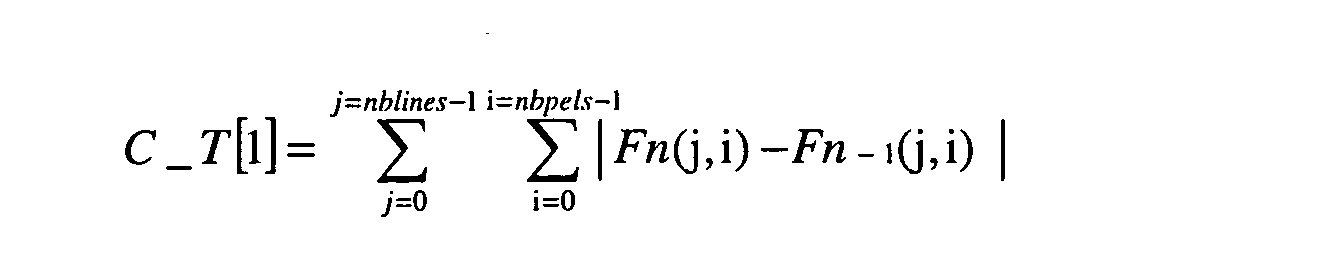
- the module 6 performs a measurement of the inter-field correlation between the second field of the current frame and the first field of the current frame denoted C_T[1].
- the module 6 performs a measurement of the inter-field correlation between the second field of the current frame and the second field of the previous frame denoted C_2T[1].
- the module 6 provides the module 7 with the inter-field and intra-field correlation measurements.
- the module 7 comprises a progressive/interlaced decision module 11 and a module 12 for calculating the weighted temporal activity.
- the module 11 determines whether the current sequence received at the input of the coding device has come from a progressive source (a film for example) or from an interlaced video source. For this purpose, it performs the following comparison: If (0.9 * (C_Intra[0]+C_Intra[1]) > C_T[1]), then the sequence is considered to be progressive, otherwise the sequence is considered to be interlaced.
- the module 12 performs a calculation of the temporal activity weighted by the spatial activity.
- the coding of frame type is appropriate for frame sequences with weak motion, that is to say frame sequences whose temporal activity is weak.
- the coding of field type is appropriate, conversely, for frame sequences with strong motion, that is to say frame sequences whose temporal activity is strong.
- the temporal activity is weighted by the spatial activity. Specifically, when the sequences are very textured and therefore exhibit strong spatial activity, the coding of frame type, keeping all the lines, gives better results than a coding in field mode which keeps only one line out of two.
- the coding is performed according to a field mode or a frame mode as a function of the value of Act and of the detection of the type of coding, progressive or interlaced, performed by the module 11.
- the choice of the coding is carried out by the module 8 which receives as input the sequence type detected and the weighted temporal activity.
- the current frame can be coded using a coding of field type, otherwise, the current frame will be coded using a coding of frame type.
- the threshold value equal to 3 may be different.
- a modification of the value of the threshold may make it possible to favour one or the other of the coding modes.
- the actual number of consecutive B frames is sometimes different from the optimal number of B frames depending on the constraints of the application.
- the maximum I/P period may in fact be imposed by requirements for short processing time in the coding/decoding chain.
- the I/P period is thus bounded by the interval [2, max I/P period].
- the value 2 corresponds to a B type frame between an I type frame and a P type frame.
- the module 8 transmits the type proposal and frame structure to the final decision module 9.
- the module 9 also receives via the module 10 the history of decisions regarding the last few frames coded. If the structure and the type of coding of the current GOP are different from those proposed by the module 8, the module 9 will take no account of this last proposal unless the structure of the current GOP and the type of coding can be modified.
- one and the same GOP can contain frames coded as a field structure or as a frame structure.
- the GOP can be shortcut so as to make it possible to switch from a coding of field type to a coding of frame type or vice versa.
- each GOP possesses a coding structure, of frame or field type, and an associated GOP structure, that are constant. When there is a change of structure, then the GOP is changed by coding the first frame in intra mode. This yields high-performance coding quality and great stability and also facilitates the implementation of bit rate regulation for closed-loop coding.
- the module 9 thereafter transmits the information necessary for the coding to the frames reorganization module 3 represented in Figure 3 and to the coding loop 4 represented in Figure 4 as well as control data to the entropy coding module 5 represented in Figure 5.
- the control data consist for example of high-level parameters indicating the entropy coding mode ("cabac” or "cavlc” under H.26L coding), the number of reference frames for the predictions, the size of the frame (width, height), the profile and the level.
- the coding control module 2 transmits the type in which the following frame should be coded (intra, bi-predictive or predictive) to the frames reorganization module 3 and transmits the structure of the frame (field or frame) to the coding loop 4.
- the frame of type I is always coded in field mode (with the second field of the frame coded as P type with respect to the first field), regardless of the structure and the mode of coding of the current GOP, onwards of the moment at which the sequence is considered to be of interlaced type.
- the B frames when the number of B frames inserted exceeds 2 (sequences with weak motion), the B frames will be used as possible reference frames for the other B frames.
- Figure 4 represents an example of a group of pictures according to this preferred embodiment.
- the period between an I frame and a P frame is 4, that is to say there are 3 B frames between an I frame and a P frame.
- the central frame B2 lying between the other two B frames, is a reference frame for the coding of the two B frames surrounding it.
- This frame B2 is coded, before the frame B1, on the basis of the previous frame I0 of the current GOP and of the following frame P4 of the current GOP.
- the frame B1 is coded on the basis of the previous frame I0 of the following frame B2 and of the following frame P4.
- the frame B3 is coded on the basis of the frame I0, of the frame B2, of the frame P4.
Landscapes
- Engineering & Computer Science (AREA)
- Multimedia (AREA)
- Signal Processing (AREA)
- Compression Or Coding Systems Of Tv Signals (AREA)
- Testing, Inspecting, Measuring Of Stereoscopic Televisions And Televisions (AREA)
Abstract
- means (1) for measuring the spatial activity of the video frames to be coded,
- means (1) for measuring the temporal activity of the video frames to be coded,
- means (2) for coding the frames as a frame structure or as a field structure.
Description
The coding of video frames is necessary for the transmission of digital video data in limited bandwidth networks as well as for applications where storage constitutes a limit.
The compression of digital video data without significant degradation of quality is possible when the video sequences display a high degree of spatial redundancy, of spectral redundancy, of temporal redundancy, of psycho-visual redundancy.
These standards are aimed at a vast gamut of applications with varied demands with regard to bit rate, to frame quality, to complexity, to resilience to error and to timescale as well as to the improvement of compression ratios.
The field or the frame consists of horizontal rows, each containing sixteen lines of pixels. In each row there are macroblocks, each being of dimensions 16*16. A macroblock is organized as four luminance blocks and as 2, 4 or 8 chrominance blocks depending on the type of sampling.
In a compression scheme formatting the data in frame mode in a macroblock, the two fields remain interlaced in a common block. In the field type coding mode, the two fields are separated in the macroblock: one block corresponds to the even field and another corresponds to the odd field.
- I (intra) frames whose coding does not depend on any other frame,
- P (predictive) frames whose coding depends on previously received frames,
- B (bi-predictive) frames which depend on frames received
previously and/or subsequently. The group of frames between two I
frames is called a GOP (standing for "Group of Pictures"), its size is
variable and its internal structure in terms of frame type is also free.
The reference model of the H.264 standard has made the choice of so-called
a-posteriori coding, that is to say after post-coding of the frame in the
frame or field structures. The coding which provided the best bit rate/distortion
compromise is adopted.
Such a mode of coding is hardly conceivable for real-time applications since it is too expensive in terms of time or calculation means: it necessitates the calculation of frame structure field predictions, frame structure frame predictions, field structure field predictions, i.e. three times as many calculations as the coding of a progressive source (frame structure frame predictions) which is already critical for a standard television format in the current state of the art.Moreover, the reference model of the standard implements a fixed GOP structure, this not guaranteeing that the choice of coding, although made in a-posteriori mode, will make it possible to obtain the best coding in terms of bit rate/distortion compromise.The present invention proposes a coding device in which the choices of coding in field or frame mode are carried out before coding.For this purpose, the invention proposes a device for coding video frame sequences, comprising - means for measuring the spatial activity of the video frames to be coded,
- means for measuring the temporal activity of the video frames to be coded,
- means for coding the frames as a frame structure or as a field
structure.
According to the invention, the means for coding the frames as a frame structure or as a field structure are able to chose the field or frame structure dynamically as a function of the measurements of spatial and temporal activity of the said frame.
The coupling of the choice of the frame/field coding structure and of the GOP structure can make it possible to exceed the performance of the reference model of the standard.
In this way, this enables a frame sequence of progressive type to be coded as a frame structure. Specifically, the progressive sequences exhibit a strong spatial correlation and it is therefore preferable to code them as a frame structure.
This may enable a reduction in the coding costs and therefore an improvement in the coding bit rate.
The invention also relates to a method of coding video data, comprising the steps of:
- measuring the spatial activity of the video frames to be coded,
- measuring the temporal activity of the video frames to be coded,
- coding the frames as a frame structure or as a field structure.
- Figure 1 represents a coding device according to a preferred embodiment of the invention,
- Figure 2 represents a preferred embodiment of a functional block diagram of the invention,
- Figure 3 represents a preferred mode of calculating the intra and inter field correlations,
- Figure 4 represents a group of pictures (GOP) according to a preferred embodiment of the invention in the case of sequences with weak motion.
The output of the
The
The entropy coding module 5 provides the coded video steam as output.
Figure 3 explains the correlation scheme used by the module 6.
The module 6 performs an intra-field correlation of the current frame by measuring the intra-field correlation of each field of the frame.
The intra-field correlation of the even field is denoted Clntra[0] and the intra-field correlation of the odd field is denoted Clntra[1] as indicated in Figure 3.


F represents the value of the luminance of pixel (i,j).
The module 6 performs a measurement of the inter-field correlation between the first field of the current frame and the last field of the previous frame denoted C_T[0].



The
The
For this purpose, it performs the following comparison:
If (0.9 * (C_Intra[0]+C_Intra[1]) > C_T[1]), then the sequence is considered to be progressive, otherwise the sequence is considered to be interlaced.
The coding of frame type is appropriate for frame sequences with weak motion, that is to say frame sequences whose temporal activity is weak.
The coding of field type is appropriate, conversely, for frame sequences with strong motion, that is to say frame sequences whose temporal activity is strong.
The temporal activity is weighted by the spatial activity. Specifically, when the sequences are very textured and therefore exhibit strong spatial activity, the coding of frame type, keeping all the lines, gives better results than a coding in field mode which keeps only one line out of two.
Otherwise, the frame is coded in frame mode.
If the
The only possible GOP structure is then I0,0 I0,1 B1,0 B1,1 P2,0 P2,1 B3,0 B3,1 P4,0 P4,1 B5,0 B5,1 P6,0 P6,1.
where i,j in Xi,j respectively represent the frame number and the field number. The length of the GOP is not fixed.
If the
In this case, the
The I/P period is thus bounded by the interval [2, max I/P period].
The
According to a preferred embodiment, the GOP can be shortcut so as to make it possible to switch from a coding of field type to a coding of frame type or vice versa. In this case, each GOP possesses a coding structure, of frame or field type, and an associated GOP structure, that are constant. When there is a change of structure, then the GOP is changed by coding the first frame in intra mode. This yields high-performance coding quality and great stability and also facilitates the implementation of bit rate regulation for closed-loop coding.
The central frame B2, lying between the other two B frames, is a reference frame for the coding of the two B frames surrounding it. This frame B2 is coded, before the frame B1, on the basis of the previous frame I0 of the current GOP and of the following frame P4 of the current GOP.
Claims (8)
- Device for coding video frame sequences, comprisingcharacterized in that the means (2) for coding the frames as a frame structure or as a field structure are able to chose the field or frame structure dynamically as a function of the measurements of spatial and temporal activity of the said frame.means (1) for measuring the spatial activity of the video frames to be coded,means (1) for measuring the temporal activity of the video frames to be coded,means (2) for coding the frames as a frame structure or as a field structure,
- Coding device according to Claim 1, characterized in that the coding means being able to code the video sequences in the form of groups of pictures (GOP), the said device comprises means for choosing the structure of the group of pictures (GOP) as a function of the measurements of spatial and temporal activity.
- Device according to one of the preceding claims, characterized in that it comprises means (11) for deciding whether the video sequences are of interlaced type or of progressive type.
- Device according to any one of the preceding claims, characterized in that the groups of pictures comprising frames coded in intra mode (I), in predictive mode (P) and in bi-predictive mode (B), the frames of bi-predictive type (B) are able to serve as reference frame for the coding of certain frames of the group of pictures (GOP).
- Device according to Claim 3, characterized in that the groups of pictures (GOP) are able to comprise sequences composed of any number of consecutive frames coded in bi-predictive mode (B).
- Device according to Claim 3, characterized in that, when the input sequence is of interlaced type, the frames of intra type (I) are coded as a field structure, the second field of the frame becoming a field of predictive type (P) with respect to the first field of the frame.
- Method of coding video data, comprising the steps ofcharacterized in that the coding of the frames as a frame structure or as a field structure is chosen dynamically as a function of the measurements of spatial and temporal activity of the said frame.measuring the spatial activity of the video frames to be coded,measuring the temporal activity of the video frames to be coded,coding the frames as a frame structure or as a field structure,
- Computer program product, characterized in that it comprises program code instructions able to implement the method according to Claim 7 when the program is executed on a computer.
Applications Claiming Priority (2)
| Application Number | Priority Date | Filing Date | Title |
|---|---|---|---|
| FR0308154 | 2003-07-04 | ||
| FR0308154A FR2857205B1 (en) | 2003-07-04 | 2003-07-04 | DEVICE AND METHOD FOR VIDEO DATA CODING |
Publications (2)
| Publication Number | Publication Date |
|---|---|
| EP1494483A2 true EP1494483A2 (en) | 2005-01-05 |
| EP1494483A3 EP1494483A3 (en) | 2005-01-19 |
Family
ID=33427687
Family Applications (1)
| Application Number | Title | Priority Date | Filing Date |
|---|---|---|---|
| EP04013925A Withdrawn EP1494483A3 (en) | 2003-07-04 | 2004-06-15 | Video coder with control of GOP structure by spatial and temporal activity |
Country Status (8)
| Country | Link |
|---|---|
| US (1) | US7577196B2 (en) |
| EP (1) | EP1494483A3 (en) |
| JP (1) | JP4669239B2 (en) |
| KR (1) | KR101146037B1 (en) |
| CN (1) | CN100588256C (en) |
| FR (1) | FR2857205B1 (en) |
| MY (1) | MY141436A (en) |
| TW (1) | TWI339524B (en) |
Cited By (4)
| Publication number | Priority date | Publication date | Assignee | Title |
|---|---|---|---|---|
| EP1816872A1 (en) * | 2006-02-07 | 2007-08-08 | Samsung Electronics Co., Ltd. | Multi-view video encoding apparatus and method |
| WO2008000737A1 (en) * | 2006-06-30 | 2008-01-03 | Thomson Licensing | Frame or field mode coding method |
| KR101146037B1 (en) * | 2003-07-04 | 2012-05-14 | 넥스트림 프랑스 | Device and method for coding video data |
| US20140140402A1 (en) * | 2007-12-17 | 2014-05-22 | General Instrument Corporation | Method and apparatus for selecting a coding mode |
Families Citing this family (13)
| Publication number | Priority date | Publication date | Assignee | Title |
|---|---|---|---|---|
| US8369405B2 (en) * | 2004-05-04 | 2013-02-05 | Qualcomm Incorporated | Method and apparatus for motion compensated frame rate up conversion for block-based low bit rate video |
| CN101010964B (en) * | 2004-07-01 | 2012-01-04 | 高通股份有限公司 | Method and apparatus for using frame rate up conversion techniques in scalable video coding |
| AU2005267171A1 (en) | 2004-07-20 | 2006-02-02 | Qualcomm Incorporated | Method and apparatus for encoder assisted-frame rate up conversion (EA-FRUC) for video compression |
| US8553776B2 (en) * | 2004-07-21 | 2013-10-08 | QUALCOMM Inorporated | Method and apparatus for motion vector assignment |
| KR100694137B1 (en) | 2005-07-08 | 2007-03-12 | 삼성전자주식회사 | A video encoding apparatus, a video decoding apparatus, and a method thereof, and a recording medium having recorded thereon a program for implementing the same. |
| KR100775787B1 (en) * | 2005-08-03 | 2007-11-13 | 경희대학교 산학협력단 | Video encoding apparatus and its method using spatiotemporal characteristics by region |
| TWI304303B (en) * | 2006-01-04 | 2008-12-11 | Sunplus Technology Co Ltd | Apparatus for image encoding and the method thereof |
| US20070230564A1 (en) * | 2006-03-29 | 2007-10-04 | Qualcomm Incorporated | Video processing with scalability |
| US8634463B2 (en) * | 2006-04-04 | 2014-01-21 | Qualcomm Incorporated | Apparatus and method of enhanced frame interpolation in video compression |
| US8750387B2 (en) * | 2006-04-04 | 2014-06-10 | Qualcomm Incorporated | Adaptive encoder-assisted frame rate up conversion |
| EP2070048B1 (en) * | 2006-09-29 | 2010-11-10 | Thomson Licensing | Spatial masking using a spatial activity metric |
| JP4892450B2 (en) * | 2007-10-17 | 2012-03-07 | パナソニック株式会社 | Image coding apparatus and image coding method |
| KR100952340B1 (en) | 2008-01-24 | 2010-04-09 | 에스케이 텔레콤주식회사 | Method and apparatus for determining coding mode using spatiotemporal complexity |
Family Cites Families (20)
| Publication number | Priority date | Publication date | Assignee | Title |
|---|---|---|---|---|
| US5347309A (en) * | 1991-04-25 | 1994-09-13 | Matsushita Electric Industrial Co., Ltd. | Image coding method and apparatus |
| JP2684941B2 (en) * | 1992-11-25 | 1997-12-03 | 松下電器産業株式会社 | Image encoding method and image encoding device |
| US5784107A (en) * | 1991-06-17 | 1998-07-21 | Matsushita Electric Industrial Co., Ltd. | Method and apparatus for picture coding and method and apparatus for picture decoding |
| JP3166835B2 (en) * | 1991-10-14 | 2001-05-14 | 株式会社ディーディーアイ | Method and apparatus for highly efficient coding of moving images |
| JP3165296B2 (en) * | 1992-12-25 | 2001-05-14 | 三菱電機株式会社 | Inter-frame coding processing method, inter-frame coding processing method, and coding control method |
| US5506844A (en) * | 1994-05-20 | 1996-04-09 | Compression Labs, Inc. | Method for configuring a statistical multiplexer to dynamically allocate communication channel bandwidth |
| JPH08275160A (en) * | 1995-03-27 | 1996-10-18 | Internatl Business Mach Corp <Ibm> | Discrete cosine conversion method |
| US5652629A (en) * | 1995-09-12 | 1997-07-29 | International Business Machines Corporation | Bidirectional motion estimation in a motion video compression system |
| US5682204A (en) * | 1995-12-26 | 1997-10-28 | C Cube Microsystems, Inc. | Video encoder which uses intra-coding when an activity level of a current macro-block is smaller than a threshold level |
| KR970057947A (en) | 1995-12-28 | 1997-07-31 | 배순훈 | Type Determination and Buffer Control Unit in Image Encoder |
| US6108039A (en) * | 1996-05-23 | 2000-08-22 | C-Cube Microsystems, Inc. | Low bandwidth, two-candidate motion estimation for interlaced video |
| FR2764156B1 (en) * | 1997-05-27 | 1999-11-05 | Thomson Broadcast Systems | PRETREATMENT DEVICE FOR MPEG II CODING |
| US6259733B1 (en) * | 1998-06-16 | 2001-07-10 | General Instrument Corporation | Pre-processing of bit rate allocation in a multi-channel video encoder |
| EP1081959B1 (en) * | 1999-09-03 | 2007-11-14 | STMicroelectronics S.r.l. | Method for recognizing a progressive or an interlaced content in a video sequence |
| JP2001169290A (en) * | 1999-12-10 | 2001-06-22 | Matsushita Electric Ind Co Ltd | Moving picture coding method, moving picture coding apparatus and moving picture coding system |
| JP4378824B2 (en) * | 2000-02-22 | 2009-12-09 | ソニー株式会社 | Image processing apparatus and method |
| EP1374429A4 (en) * | 2001-03-05 | 2009-11-11 | Intervideo Inc | Systems and methods for encoding and decoding redundant motion vectors in compressed video bitstreams |
| JP2003333505A (en) * | 2002-05-14 | 2003-11-21 | Pioneer Electronic Corp | Recording medium, video recording apparatus, video reproducing apparatus, and video recording and reproducing apparatus |
| US7020200B2 (en) * | 2002-08-13 | 2006-03-28 | Lsi Logic Corporation | System and method for direct motion vector prediction in bi-predictive video frames and fields |
| FR2857205B1 (en) * | 2003-07-04 | 2005-09-23 | Nextream France | DEVICE AND METHOD FOR VIDEO DATA CODING |
-
2003
- 2003-07-04 FR FR0308154A patent/FR2857205B1/en not_active Expired - Fee Related
-
2004
- 2004-06-15 EP EP04013925A patent/EP1494483A3/en not_active Withdrawn
- 2004-07-01 TW TW093119869A patent/TWI339524B/en not_active IP Right Cessation
- 2004-07-02 JP JP2004196600A patent/JP4669239B2/en not_active Expired - Fee Related
- 2004-07-02 US US10/884,158 patent/US7577196B2/en active Active
- 2004-07-02 MY MYPI20042648A patent/MY141436A/en unknown
- 2004-07-02 KR KR1020040051572A patent/KR101146037B1/en not_active Expired - Fee Related
- 2004-07-05 CN CN200410062160A patent/CN100588256C/en not_active Expired - Fee Related
Cited By (8)
| Publication number | Priority date | Publication date | Assignee | Title |
|---|---|---|---|---|
| KR101146037B1 (en) * | 2003-07-04 | 2012-05-14 | 넥스트림 프랑스 | Device and method for coding video data |
| EP1816872A1 (en) * | 2006-02-07 | 2007-08-08 | Samsung Electronics Co., Ltd. | Multi-view video encoding apparatus and method |
| US8542734B2 (en) | 2006-02-07 | 2013-09-24 | Samsung Electronics Co., Ltd. | Multi-view video encoding apparatus and method |
| WO2008000737A1 (en) * | 2006-06-30 | 2008-01-03 | Thomson Licensing | Frame or field mode coding method |
| FR2903271A1 (en) * | 2006-06-30 | 2008-01-04 | Thomson Licensing Sa | FRAME OR BITRAME MODE ENCODING METHOD |
| US8428132B2 (en) | 2006-06-30 | 2013-04-23 | Thomson Licensing | Frame or field mode coding method |
| US20140140402A1 (en) * | 2007-12-17 | 2014-05-22 | General Instrument Corporation | Method and apparatus for selecting a coding mode |
| US9270985B2 (en) * | 2007-12-17 | 2016-02-23 | Arris Enterprises, Inc. | Method and apparatus for selecting a coding mode |
Also Published As
| Publication number | Publication date |
|---|---|
| MY141436A (en) | 2010-04-30 |
| JP2005033789A (en) | 2005-02-03 |
| EP1494483A3 (en) | 2005-01-19 |
| KR101146037B1 (en) | 2012-05-14 |
| TW200509675A (en) | 2005-03-01 |
| FR2857205A1 (en) | 2005-01-07 |
| US7577196B2 (en) | 2009-08-18 |
| US20050117644A1 (en) | 2005-06-02 |
| TWI339524B (en) | 2011-03-21 |
| KR20050004112A (en) | 2005-01-12 |
| CN100588256C (en) | 2010-02-03 |
| FR2857205B1 (en) | 2005-09-23 |
| CN1578470A (en) | 2005-02-09 |
| JP4669239B2 (en) | 2011-04-13 |
Similar Documents
| Publication | Publication Date | Title |
|---|---|---|
| US7577196B2 (en) | Device and method for coding video data | |
| EP0542474B1 (en) | Adaptive coding and decoding of frames and fields of video signals | |
| KR100340369B1 (en) | Encoding method | |
| US5237413A (en) | Motion filter for digital television system | |
| US5835149A (en) | Bit allocation in a coded video sequence | |
| US6587509B1 (en) | Reducing undesirable effects of an emphasis processing operation performed on a moving image by adding a noise signal to a decoded uncompressed signal | |
| US5150432A (en) | Apparatus for encoding/decoding video signals to improve quality of a specific region | |
| US9374577B2 (en) | Method and apparatus for selecting a coding mode | |
| US6603815B2 (en) | Video data processing apparatus, video data encoding apparatus, and methods thereof | |
| US6005981A (en) | Quadtree-structured coding of color images and intra-coded images | |
| KR100504641B1 (en) | Image encoder and image encoding method | |
| EP1127467B1 (en) | Error concealment in a video signal | |
| EP1445962A1 (en) | Adaptive variable-length coding and decoding methods for image data | |
| US20030161402A1 (en) | Motion wake identification and control mechanism | |
| WO2003063501A1 (en) | Coding transform coefficients in image/video encoders and/or decoders | |
| EP1143737A2 (en) | Image encoding apparatus and method, video camera, image recording apparatus, and image transmission apparatus | |
| EP0599529B1 (en) | Method and apparatus for picture coding and method and apparatus for picture decoding | |
| US20060198439A1 (en) | Method and system for mode decision in a video encoder | |
| EP0987903B1 (en) | Method for image compression and device for implementing the method | |
| US7024052B2 (en) | Motion image decoding apparatus and method reducing error accumulation and hence image degradation | |
| GB2417630A (en) | Encoding a video signal based on the activity within the video signal | |
| JPH06292179A (en) | Orthogonal transform coding device and orthogonal transform decoding device | |
| JPH06141302A (en) | Motion information differencer and inverse differencer | |
| Fitzek et al. | VideoMeter tool for YUV bitstreams | |
| Bhaskaran et al. | The H. 261 Video Coding Standard |
Legal Events
| Date | Code | Title | Description |
|---|---|---|---|
| PUAI | Public reference made under article 153(3) epc to a published international application that has entered the european phase |
Free format text: ORIGINAL CODE: 0009012 |
|
| PUAL | Search report despatched |
Free format text: ORIGINAL CODE: 0009013 |
|
| AK | Designated contracting states |
Kind code of ref document: A2 Designated state(s): AT BE BG CH CY CZ DE DK EE ES FI FR GB GR HU IE IT LI LU MC NL PL PT RO SE SI SK TR |
|
| AX | Request for extension of the european patent |
Extension state: AL HR LT LV MK |
|
| AK | Designated contracting states |
Kind code of ref document: A3 Designated state(s): AT BE BG CH CY CZ DE DK EE ES FI FR GB GR HU IE IT LI LU MC NL PL PT RO SE SI SK TR |
|
| AX | Request for extension of the european patent |
Extension state: AL HR LT LV MK |
|
| 17P | Request for examination filed |
Effective date: 20050620 |
|
| AKX | Designation fees paid |
Designated state(s): DE FR GB IT |
|
| 17Q | First examination report despatched |
Effective date: 20070413 |
|
| RAP1 | Party data changed (applicant data changed or rights of an application transferred) |
Owner name: THOMSON LICENSING |
|
| STAA | Information on the status of an ep patent application or granted ep patent |
Free format text: STATUS: THE APPLICATION IS DEEMED TO BE WITHDRAWN |
|
| 18D | Application deemed to be withdrawn |
Effective date: 20150106 |