EP1494465A1 - Image enlarging device and method - Google Patents
Image enlarging device and method Download PDFInfo
- Publication number
- EP1494465A1 EP1494465A1 EP03715488A EP03715488A EP1494465A1 EP 1494465 A1 EP1494465 A1 EP 1494465A1 EP 03715488 A EP03715488 A EP 03715488A EP 03715488 A EP03715488 A EP 03715488A EP 1494465 A1 EP1494465 A1 EP 1494465A1
- Authority
- EP
- European Patent Office
- Prior art keywords
- image
- line count
- zoom
- signal
- vertical
- Prior art date
- Legal status (The legal status is an assumption and is not a legal conclusion. Google has not performed a legal analysis and makes no representation as to the accuracy of the status listed.)
- Withdrawn
Links
Images




Classifications
-
- H—ELECTRICITY
- H04—ELECTRIC COMMUNICATION TECHNIQUE
- H04N—PICTORIAL COMMUNICATION, e.g. TELEVISION
- H04N5/00—Details of television systems
- H04N5/222—Studio circuitry; Studio devices; Studio equipment
- H04N5/262—Studio circuits, e.g. for mixing, switching-over, change of character of image, other special effects ; Cameras specially adapted for the electronic generation of special effects
- H04N5/2628—Alteration of picture size, shape, position or orientation, e.g. zooming, rotation, rolling, perspective, translation
-
- H—ELECTRICITY
- H04—ELECTRIC COMMUNICATION TECHNIQUE
- H04N—PICTORIAL COMMUNICATION, e.g. TELEVISION
- H04N23/00—Cameras or camera modules comprising electronic image sensors; Control thereof
- H04N23/60—Control of cameras or camera modules
- H04N23/69—Control of means for changing angle of the field of view, e.g. optical zoom objectives or electronic zooming
-
- H—ELECTRICITY
- H04—ELECTRIC COMMUNICATION TECHNIQUE
- H04N—PICTORIAL COMMUNICATION, e.g. TELEVISION
- H04N23/00—Cameras or camera modules comprising electronic image sensors; Control thereof
- H04N23/60—Control of cameras or camera modules
- H04N23/63—Control of cameras or camera modules by using electronic viewfinders
- H04N23/633—Control of cameras or camera modules by using electronic viewfinders for displaying additional information relating to control or operation of the camera
- H04N23/635—Region indicators; Field of view indicators
-
- H—ELECTRICITY
- H04—ELECTRIC COMMUNICATION TECHNIQUE
- H04N—PICTORIAL COMMUNICATION, e.g. TELEVISION
- H04N5/00—Details of television systems
- H04N5/76—Television signal recording
- H04N5/765—Interface circuits between an apparatus for recording and another apparatus
- H04N5/775—Interface circuits between an apparatus for recording and another apparatus between a recording apparatus and a television receiver
- H04N5/7755—Interface circuits between an apparatus for recording and another apparatus between a recording apparatus and a television receiver the recorder being connected to, or coupled with, the antenna of the television receiver
-
- H—ELECTRICITY
- H04—ELECTRIC COMMUNICATION TECHNIQUE
- H04N—PICTORIAL COMMUNICATION, e.g. TELEVISION
- H04N5/00—Details of television systems
- H04N5/76—Television signal recording
- H04N5/78—Television signal recording using magnetic recording
- H04N5/781—Television signal recording using magnetic recording on disks or drums
-
- H—ELECTRICITY
- H04—ELECTRIC COMMUNICATION TECHNIQUE
- H04N—PICTORIAL COMMUNICATION, e.g. TELEVISION
- H04N5/00—Details of television systems
- H04N5/76—Television signal recording
- H04N5/84—Television signal recording using optical recording
- H04N5/85—Television signal recording using optical recording on discs or drums
-
- H—ELECTRICITY
- H04—ELECTRIC COMMUNICATION TECHNIQUE
- H04N—PICTORIAL COMMUNICATION, e.g. TELEVISION
- H04N9/00—Details of colour television systems
- H04N9/79—Processing of colour television signals in connection with recording
- H04N9/80—Transformation of the television signal for recording, e.g. modulation, frequency changing; Inverse transformation for playback
- H04N9/804—Transformation of the television signal for recording, e.g. modulation, frequency changing; Inverse transformation for playback involving pulse code modulation of the colour picture signal components
- H04N9/8042—Transformation of the television signal for recording, e.g. modulation, frequency changing; Inverse transformation for playback involving pulse code modulation of the colour picture signal components involving data reduction
Definitions
- the present invention relates to an image enlarging apparatus and an image enlarging method that can immediately produce a digital image zooming effect with little image degradation.
- a conventional image enlarging system such as used in video cameras to provide a digital zoom function is described below.
- the lens unit 201 includes a zoom lens 201b for optically enlarging and reducing images, and a zoom motor 201a for moving the zoom lens 201b along the optical axis of the lens.
- the CCD 202 is a charge-coupled device for imaging an incident optical signal of the subject and converting the optical signal to an electrical image signal.
- the analog signal processor 203 then boosts the output level of the image signal from the CCD 202.
- the A/D converter 204 is an analog/digital converter for converting the analog image signal output from the analog signal processor 203 to a digital signal.
- the image quality processing circuit 205 of the digital signal processor 200 then applies gamma correction, aperture correction, or other image processing operation to the image signal from the A/D converter 204.
- the vertical image signal processing circuit 206 then processes the image from the image quality processing circuit 205 in the vertical scanning direction to compress the vertical line count of the image signal from the image quality processing circuit 205 according to the vertical line count of a particular television format.
- the horizontal image signal processing circuit 207 horizontally processes the image from the vertical image signal processing circuit 206 to compress the horizontal line count (horizontal pixel count) of the image signal from the vertical image signal processing circuit 206 according to the horizontal resolution of the particular television format.
- the image size adjusting circuit 210 is the digital zooming circuit for electronically enlarging or reducing the image signal from the horizontal image signal processing circuit 207 to a desirable image size.
- the microprocessor 214 is the control means for controlling the circuits of the digital signal processor 200.
- the zoom switch 215 is equivalent to the zoom lever or zoom button of a typical video camera. The zoom switch 215 can be used for continuous optical and digital zooming.
- the zoom motor control signal processor 212 outputs control signals controlling the zoom direction and amount, that is, the direction and distance of zoom lens movement, as instructed by the microprocessor 214 to the zoom lens drive circuit 213.
- the zoom lens drive circuit 213 drives the zoom motor 201a of the lens unit 201 based on the control signals from the zoom motor control signal processor 212.
- the CCD drive circuit 211 likewise drives the CCD 202 as controlled by the microprocessor 214.
- first image area 31a is captured by the CCD 202 and output from image quality processing circuit 205.
- the vertical line count in this example is 720 horizontal lines.
- Subject image 33a is formed in first image area 31a.
- the second image area 32a compresses the number of lines in the vertical and horizontal directions so that the image formed in the first image area 31a matches a particular television format. Images in the second image area 32a are thus compressed to a vertical line count of 480 horizontal lines in this example.
- Cropping area 36a is the image area presented on the second image area 32a when the zoom switch 215 is operated to enlarge the subject. As the magnification ratio of the zoom lens increases, the number of vertical and horizontal lines in the second cropping area 36a decreases.
- the zoomed image contains image information from a 320-line area of the original image.
- the output image area 35a is the image from second cropping area 36a converted to an image with a vertical line count of 480 lines for presentation.
- the optical signal of the subject incident on the CCD 202 through the lens groups of the lens unit 201 is converted to an electrical image signal and output to the analog signal processor 203.
- the signal level from the CCD 202 is low, and the analog signal processor 203 therefore applies a signal level amplification process to boost the signal, which is then A/D converted by the A/D converter 204.
- the output signal from the A/D converter 204 is input to image quality processing circuit 205, which applies gamma correction, aperture correction, or other signal processing, resulting in an image such as shown in first image area 31a in Fig. 2 (a) being input to the vertical image signal processing circuit 206.
- the vertical image signal processing circuit 206 compresses the vertical line count of the image shown in the first image area 31a in Fig. 2 (a) to match the effective vertical line count of the television format. Because the vertical line count of an image from the image quality processing circuit 205 is 720 in this example, this line count compression process reduces the line count to 2/3 or 480 lines.
- the vertical image signal processing circuit 206 outputs the compressed image to the horizontal image signal processing circuit 207, which compresses the horizontal resolution according to the vertical compression as described above. The image resulting from this process is shown in second image area 32a in Fig. 2 (a). By thus compressing the line count of the image, it is possible to reduce only the size while keeping the same view angle as the image from the CCD 202.
- the image signal from the horizontal image signal processing circuit 207 is then passed through the image size adjusting circuit 210 and output from the output terminal.
- a digital signal compression circuit display means then image compresses the image signal output from the image size adjusting circuit 210, and then outputs the compressed image signal to a display means (the LCD or electronic viewfinder of a video camera, for example) or recording means (a device for recording the signal to tape, disc, or other recording medium).
- the microprocessor 214 controls the zoom lens drive circuit 213 to determine the current zoom ratio of the optical zoom lens. If the zoom ratio is from 1X to 10X, the microprocessor 214 controls the zoom motor control signal processor 212 so that the input image is enlarged or reduced. This command causes the zoom motor control signal processor 212 to generate a control signal for driving the zoom lens 201b based on how the zoom switch 215 is operated, that is, whether to zoom to telephoto or wide angle, and how far. The resulting control signal is output to the zoom lens drive circuit 213.
- the zoom lens drive circuit 213 controls the zoom motor 201a based on this control signal, and thereby moves the zoom lens 201b along the optical axis. The zooming direction and distance are determined by the control signal generated by the zoom motor control signal processor 212.
- the zoom lens 201b thus moves to the controlled position, the CCD 202 converts the optical signal to an electrical signal, and outputs this electrical signal to the analog signal processor 203 as an image signal.
- the analog signal processor 203 boosts the image signal level and outputs the boosted image signal to the A/D converter 204 for analog/digital signal conversion.
- the resulting digital image signal is then corrected by gamma correction or aperture correction, for example, by the image quality processing circuit 205, and the vertical and horizontal resolution are then compressed by the vertical image signal processing circuit 206 and horizontal image signal processing circuit 207 to match the line count of the specified television signal format.
- the compressed image signal is then output through the image size adjusting circuit 210.
- the image enlarged or reduced by the zoom lens 201b is input to the image quality processing circuit 205 as the image shown in first image area 31a in Fig. 2 (a).
- the image signal ultimately output from the output terminal is therefore the image as shown in second image area 32a.
- the microprocessor 214 instructs the image size adjusting circuit 210 to enlarge or reduce the input image signal accordingly.
- the image signal shown in second image area 32a in Fig. 2 (a) is input to the image size adjusting circuit 210, and the middle part of this image signal (the cropping area 36a) is extracted and digitally enlarged to the zoom ratio specified by the zoom switch 215.
- An image signal enlarged 1.5X for example, is acquired by extracting a 320-line section from the middle of the second image area 32a containing 480 horizontal lines, and then digitally converting this 320-line section to a 480-line image.
- the vertical image signal processing circuit 206 and horizontal image signal processing circuit 207 compress the vertical and horizontal line counts of the image, and the compressed image is then enlarged by the image size adjusting circuit 210. This enlarging process degrades the image resolution (particularly the vertical resolution), and thus reduces overall image quality.
- the present invention is directed to solving this problem, and an object of the invention is to provide an image enlarging apparatus and method providing an instantaneous image enlargement function with little image degradation.
- an image enlarging apparatus has a charge-coupled device for converting an optical signal of a subject to an electrical image, a signal processing means for compressing the line counts of images from the CCD to the line counts of a particular television format, a user-operable selection means, and a control means for controlling the signal processing means based on how the selection means is operated.
- the control means instructs the signal processing means to skip the image compression process and crop the image from the CCD to an image of the line count matching the television format.
- the image enlarging apparatus and method of this invention provides an instantaneous image zooming effect with little image quality degradation.
- the present invention as described in claim 1 below has a charge-coupled device for converting an optical signal of a subject image to an electrical image signal, a signal processing means for compressing the line counts of images from the CCD to the equivalent effective line counts of a particular television format, a user-operable selection means, and a control means for controlling the signal processing means based on operation of the selection means.
- the control means instructs the signal processing means to skip the image compression process and crop the image from the CCD to an image of the line count matching the television format.
- the apparatus and method of the present invention therefore provides an immediate digital image zooming effect with little image quality degradation.
- Fig. 1 is a block diagram showing the configuration of an image enlarging apparatus according to a preferred embodiment of the invention.
- the lens unit 101 has a zoom lens 101b for optically enlarging or reducing a subject image, and a zoom motor 101a for moving the zoom lens 101b along the optical axis of the lens.
- the CCD 102 images and converts the incident optical signal of the subject to an electrical image signal.
- the analog signal processor 103 then boosts the output signal level of the image signal from the CCD 102.
- the A/D converter 104 then analog/digital converts the analog image signal from the analog signal processor 103 to a digital signal, and thus supplies a digital image signal to the digital signal processor (DSP) 100.
- DSP digital signal processor
- the image quality processor 105 of the DSP 100 applies gamma correction, aperture correction, or other correction process to the image signal from the A/D converter 104.
- the vertical image signal processing circuit 106 applies signal processing in the vertical direction of the image from the image quality processor 105, and more specifically compresses the vertical line count of the image signal from the image quality processor 105 according to the vertical line count of a particular television format.
- the horizontal image signal processing circuit 107 applies signal processing in the horizontal direction to the image from the vertical image signal processing circuit 106, and more particularly compresses the horizontal line (pixel) count of the image signal from the vertical image signal processing circuit 106 according to the horizontal line count of the television format. Note that the vertical and horizontal image signal processing circuits 106 and 107 constitute the signal processing means of the accompanying claims.
- the image trimming circuit 108 crops the image signal from the image quality processor 105 to a center part of the image.
- Selector switch 109 selects and passes to the image sizing circuit 110 signal output from the horizontal image signal processing circuit 107 or from the image trimming circuit 108.
- the image sizing circuit 110 then digitally enlarges or reduces the image signal from the horizontal image signal processing circuit 107 or image trimming circuit 108, and outputs the resized image.
- the image sizing circuit 110 is thus a so-called digital zoom circuit.
- a microprocessor 114 is a control means for controlling the circuits of the DSP 100.
- a first zoom switch 115 is equivalent to the zoom lever or button of a normal video camera, and is used for continuous zooming through the entire optical and digital zooming range. The function for enlarging an image as a result of operating this first zoom switch 115 is referred to herein as a first enlarging function.
- the second zoom switch 116 is a selection means that can be operated to immediately acquire an enlarged image. In this embodiment of the invention the image presented by operating the second zoom switch 116 is magnified 1.5X from the image observed before the second zoom switch 116 is operated.
- the enlarging function that is operated using this second zoom switch 116 is referred to herein as the second enlarging function (or instantaneous zoom function).
- the operating unit 117 is used to control the part of the image that is cropped by the image trimming circuit 108 and presented.
- the zoom motor control signal processor 112 of the DSP 100 is controlled by the microprocessor 114 and outputs control signals telling the zoom lens drive circuit 113 the direction and distance to move the zoom lens.
- the zoom lens drive circuit 113 drives the zoom motor 101a of the lens unit 101 based on control signals from the zoom motor control signal processor 112, and the CCD drive circuit 111 drives the CCD 102 as controlled by the microprocessor 114.
- the image quality processor 105, vertical image signal processing circuit 106, horizontal image signal processing circuit 107, image trimming circuit 108, selector switch 109, image sizing circuit 110, and zoom motor control signal processor 112 form a DSP 100, which can be built in a single chip.
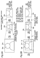
- Fig. 2 schematically describes the operating principle of an image enlarging apparatus, (a) describing operation when the first zoom switch 115 is operated, and (b) describing operation when the second zoom switch 116 is operated.
- the first image areas 31a and 31b denote the image area captured by the CCD 102 and output from the image quality processor 105, and thus represent the raw photographed image.
- the vertical and horizontal line counts of this photographed image are greater than the vertical and horizontal line counts of the television format.
- the vertical line count as used herein is the number of horizontal lines counted in the vertical direction of the image, and thus denotes the vertical resolution of the image.
- the horizontal line count is the number of pixels on each horizontal line, and thus denotes the horizontal resolution of the image.
- the line count in the horizontal direction that is, the number of pixels on each horizontal line, is 971 in the captured image and 720 in the television format.
- Subject images 33a and 33b are formed in first image areas 31a and 31b.
- the second image area 32a represents a compressed image acquired by compressing the number of lines in the vertical and horizontal directions so that the image formed in the first image area 31a matches a particular television format.
- Second image area 32b represents a cropped image acquired by trimming the photographed image in first image area 31b to the vertical and horizontal line counts of the television format.
- the cropping area 34 is the area extracted from the middle of the photographed image when the second zoom switch 116 is operated.
- the vertical line count of this cropping area 34 is 480 lines in order to match the vertical line count of the television format.
- Cropping area 36a is the area of the second image area 32a that is extracted when the first zoom switch 115 is operated
- cropping area 36b is the area of the second image area 32b that is extracted when the second zoom switch 116 is operated.
- the higher the digital zoom ratio the lower the vertical and horizontal line counts of second cropping areas 36a and 36b. If the digital zoom is set to 1.5X, for example, the extracted image area is 320 lines high.
- Output image areas 35a and 35b contain the images from the second cropping areas 36a and 36b converted to a 480 vertical line count for presentation.
- the microprocessor 114 When the first zoom switch 115 is operated, the microprocessor 114 activates the image quality processor 105, vertical image signal processing circuit 106, horizontal image signal processing circuit 107, and image sizing circuit 110, and sets the selector switch 109 to side b.
- the microprocessor 114 When the second zoom switch 116 is operated, the microprocessor 114 activates the image quality processor 105, image trimming circuit 108, and image sizing circuit 110, and sets the selector switch 109 to side a. If both first zoom switch 115 and second zoom switch 116 are operated simultaneously, the second zoom switch 116 is ignored and operation continues as though the first zoom switch 115 was operated.
- the optical image of the subject incident on the CCD 102 through the lens groups of the lens unit 101 is converted to an electrical image signal, which is output to the analog signal processor 103.
- the signal level of the CCD 102 output is low, and the analog signal processor 103 therefore boosts the signal level before conversion from an analog signal to a digital signal by the A/D converter 104.
- the output signal from the A/D converter 104 is input to the image quality processor 105, which applies gamma correction, aperture correction, or other signal processing operation, and the image shown in the first image area 31a in Fig. 2 (a) is thus input to the vertical image signal processing circuit 106.
- the vertical image signal processing circuit 106 then compresses the vertical line count of the image shown in first image area 31a in Fig. 2 (a) to a line count matching the equivalent effective vertical line count of the television format. Because the vertical line count of images from the image quality processor 105 is 720 in this embodiment, this line count is compressed to 2/3 or 480 lines.
- the image output from the vertical image signal processing circuit 106 is then input to the horizontal image signal processing circuit 107 for compressing the horizontal line count according to the vertical compression.
- the image at this time is as shown in the second image area 32a.
- the image signal from the horizontal image signal processing circuit 107 is then output through selector switch 109 and image sizing circuit 110 and the output terminal.
- a digital signal compression circuit display means then image compresses the output image signal, and then outputs the compressed image signal to a display means (the LCD or electronic viewfinder of a video camera, for example) or recording means (a device for recording the signal to tape, disc, or other recording medium).
- Fig. 3 is a graph showing the relationship between zoom ratio and output image size.
- Curve A represents performance when the first enlarging function is operated without using the second enlarging function
- curve B represents performance when the first enlarging function is operated when the second enlarging function is also used.
- These curves assume a zoom system featuring a 10X optical zoom and a 20X or higher digital zoom.
- the optical zoom is used for image enlargement from 1X to 10X
- the digital zoom is used for image enlargement at zoom ratios exceeding 10X.
- the output image size increases as the zoom ratio increases.
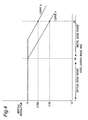
- Fig. 4 is a graph showing the relationship between zoom ratio and vertical resolution.
- Curve A represents performance when the first enlarging function is operated without using the second enlarging function
- curve B represents performance when the first enlarging function is operated when the second enlarging function is also used.
- there is no drop in the vertical resolution on either curve A or B in the optical zoom range that is, when the zoom ratio is from 1X to 10X.
- the zoom ratio exceeds 10X that is, enters the digital zoom range
- the vertical resolution drops on curve A when the zoom ratio surpasses 10X.
- the microprocessor 114 controls the zoom lens drive circuit 113 and acquires the current optical zoom ratio. If the zoom ratio is from 1X to 10X, the microprocessor 114 instructs the zoom motor control signal processor 112 so that the input image is enlarged or reduced accordingly. This command causes the zoom motor control signal processor 112 to generate a control signal for driving the zoom lens 101b based on first zoom switch 115 operation, that is, how far to zoom and whether to zoom in the telephoto or wide-angle direction. The resulting control signal is applied to the zoom lens drive circuit 113, which drives the zoom motor 101a based on this control signal and moves the zoom lens 101b along the optical axis of the lens. The zoom direction and distance are determined by the control signal generated by the zoom motor control signal processor 112.
- the CCD 102 converts the optical signal to an electrical signal, and outputs the electrical image signal to the analog signal processor 103.
- the analog signal processor 103 boosts the signal level of the analog image signal and then outputs the analog image signal to the A/D converter 104 for conversion to a digital signal.
- the resulting digital image signal is then processed by the image quality processor 105 for gamma correction or aperture correction, for example, and the vertical and horizontal line counts of the corrected image signal are then compressed by the vertical and horizontal image signal processing circuits 106 and 107 to match the line counts of the particular television signal format.
- the compressed image signal is then output through the selector switch 109 and image sizing circuit 110.
- the image enlarged or reduced by the zoom lens 101b is input to the image quality processor 105 as the image shown in first image area 31a in Fig. 2 (a), and the image signal ultimately output from the output terminal is the image shown in second image area 32a.
- the microprocessor 114 controls the image sizing circuit 110 to enlarge or reduce the input image signal.
- the image signal shown in second image area 32a in Fig. 2 (a) is input to the image sizing circuit 110, which then extracts the middle part (i.e., cropping area 36a) of the image signal and digitally enlarges the extracted image area to the magnification indicated by the first zoom switch 115.
- 320 horizontal lines are extracted from the center of the second image area 32a, which has a vertical resolution of 480 horizontal lines, digitally enlarges the extracted image area to an image with 480 horizontal lines, and outputs the result to output image area 35a as the image signal enlarged 15X.
- a 320-line image can be enlarged to a 480-line image using a line interpolation process whereby signals for the non-existent lines are interpolated based on signal values in existing adjacent lines.
- the ultimately output image signal is therefore a 480-line image presented in output image area 35a, but the image resolution is equivalent to only 320 lines.
- An approximately 320-line image area is cropped from the second image area 32a in order to enlarge the image 15X in the above example. Because the vertical line count of the output image area 35a is fixed at 480 lines, however, the size of the cropping area 36a becomes smaller and the vertical line count decreases when the enlargement ratio is even higher. Therefore, as will also be known from curve A in Fig. 4, the vertical resolution drops as the zoom ratio increases.
- the microprocessor 114 sets the selector switch 109 to side a and activates the image trimming circuit 108. This causes the image quality processor 105 to output the processed image signal to the image trimming circuit 108 for image cropping.
- This cropping operation is described below with reference to Fig. 2 (b).
- the image signal acquired through the lens unit 101, CCD 102, analog signal processor 103, A/D converter 104, and image quality processor 105 has a vertical line count of 720 lines as shown in first image area 31b in Fig. 2 (b).
- This image signal is input to the image trimming circuit 108, which extracts the center 480 lines of the first image area 31b as shown in cropping area 34, thereby acquiring an image signal as shown in second image area 32b.
- the top and bottom of the subject 33 are cut off in the second image area 32b, and the subject image is relatively larger.
- the vertical and horizontal line counts are not compressed in this cropping process.
- the area cropped in the horizontal direction is also determined automatically according to the vertical line count of the cropped image area so that the vertical and horizontal line counts of the final image are the same as those of the television format.
- the resulting image signal is then output to the image sizing circuit 110.
- the image sizing circuit 110 outputs the image without enlargement or reduction.
- the size of the image acquired when the second zoom switch 116 is operated is 1.5X the image size before the second zoom switch 116 was operated.
- the relationship between zoom ratio and image size when the second zoom switch 116 is not operated is described by curve A in Fig. 3, but is described by curve B in Fig. 3 when the second zoom switch 116 is then operated.
- the zoom ratio is set to 10X and the second zoom switch 116 is then operated, the actual image size is enlarged from 10X to 15X.
- the image enlarged by the lens unit 101 is cropped by the image trimming circuit 108 and there is no drop in resolution because there is no vertical and horizontal compression.
- response that is, the time from when the second zoom switch 116 is operated to output of the enlarged image, is significantly faster than when the first zoom switch 115 is operated to acquire an image enlarged 1.5 times.
- the microprocessor 114 controls image sizing circuit 110 to enlarge or reduce the image signal output from the image trimming circuit 108 accordingly.
- the image sizing circuit 110 crops the image signal in second image area 32b acquired from the image trimming circuit 108 to the image shown in second cropping area 36b.
- This second cropping area 36b varies according to the zoom ratio of the digital zoom. As the zoom ratio increases, the size of the second cropping area 36b decreases.
- the image signal extracted from the second cropping area 36b is then enlarged to the vertical line count (720 lines) and horizontal line count (480 lines) of the television format, and an image signal as shown in output image area 35b is output.
- the image trimming circuit 108 crops the image to a defined area of the captured image without using compression, thereby improving the resolution of the output image while eliminating the time needed for image compression or other signal processing. As a result, an enlarged image can be immediately presented.
- Fig. 6 is a block diagram showing the internal configuration of the image trimming circuit 108 shown in Fig. 1 and further described below.
- Image signals from the image quality processor 105 are input to input terminal 51.
- Image signals input to the input terminal 51 are stored to image memory 52, which could be frame memory or line memory but is preferably line memory due to cost considerations.
- Image signals read from the image memory 52 are output to the selector switch 109 in Fig. 1 from the output terminal 53.
- Control signals from the microprocessor 114 are applied to control input terminal 54.
- start point controller 56 sets the cropping area start point (the "start point” below) and outputs a start point signal.
- the end point controller 57 sets the cropping area end point (the "end point” below) and outputs an end point signal.
- the read controller 55 controls reading images from the image memory 52.
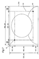
- Fig. 7 corresponds to the image shown in Fig. 2 (b) with various line count values shown for easier understanding.
- Start point 61 and end point 62 are shown.
- the image trimming circuit 108 thus defines one corner point of a rectangular cropping area as the start point 61 and sets the diagonally opposite corner point as the end point 62 on the photographed image.
- the start point 61 and end point 62 are each defined by the (x,y) coordinate values from the top left corner of the first image area 31b. More specifically, as shown in Fig. 7, the y-coordinate of the start point 61 of the cropping area 34 is the line count from the first horizontal line of the first image area 31b, and the x-coordinate is the line count (pixel count) from the left end of that line in the horizontal direction. In the example shown here the top 120 lines from the top horizontal line and the first 160 vertical lines (pixels) from the left edge are not needed.
- the starting point in the vertical direction, i.e., the y-coordinate of the start point 61 is therefore line 121, and the starting point in the horizontal direction, i.e., the x-coordinate, is line (pixel) 161.
- the coordinates of the end point 62 of the cropping area 34 in Fig. 7 are similarly determined. More specifically, the y-coordinate of the end point 62 of the cropping area 34 is the line count from the first horizontal line of the first image area 31b, and the x-coordinate is the line count (pixel count) from the left end of that line in the horizontal direction.
- the end point in the vertical direction, i.e., the y-coordinate, is therefore line 600
- the end point in the horizontal direction, i.e., the x-coordinate is line (pixel) 800.
- start and end points are both defined in this example, the end point could be calculated on-the-fly from the start point based on the 4:3 aspect ratio of the selected television format.
- the size of the cropped image signal read from the image memory 52 is therefore 480 horizontal lines by 640 vertical lines.
- the microprocessor 114 sets the selector switch 109 to side a so that image signals from the image quality processor 105 are applied to the input terminal 51 of the image trimming circuit 108. Image signals input to the input terminal 51 are written temporarily to image memory 52.
- control signal from the microprocessor 114 is also applied to the control input terminal 54.
- the control signal input to the control input terminal 54 contains a control signal for activating the image trimming circuit 108 as well as the start and end point values of the cropping area.
- the control signal applied to the control input terminal 54 is then applied to the start point controller 56 and end point controller 57.
- the start point controller 56 then generates a start point signal based on the value of the start point detected from the applied control signal.
- the end point controller 57 [56, sic] likewise generates an end point signal based on the coordinates of the end point detected from the control signal.
- the read controller 55 determines where to start cropping the image signal written to the image memory 52. Using a line counter not shown, the read controller 55 counts the vertical and horizontal line counts to locate the coordinates of the start point 61 in Fig. 7, that is, line 121 vertically and line 161 horizontally. Based on the end point signal, the read controller 55 likewise determines the end point of the cropped image. Using a line counter not shown, the read controller 55 counts the vertical and horizontal line counts to locate the coordinates of the end point 62 in Fig. 7, that is, line 600 vertically and line 800 horizontally. The limits of the first cropping area 34 are thus determined.
- the read controller 55 uses the line counter to counts the vertical and horizontal line counts of the image signal in the image memory 52. Reading starts when the start point 61 is detected and continues until the end point 62 is detected, thereby reading the image signal for the area shown as first cropping area 34.
- the image signal read from image memory 52 is output from output terminal 53 and then output from side a of the selector switch 109 shown in Fig. 1.
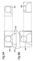
- the location of the first cropping area 34 can be desirably set as indicated by frames 34a and 34b in Fig. 5 using an operating unit 117 such as cursor keys, for example, as shown in Fig. 8.
- an operating unit 117 such as cursor keys, for example, as shown in Fig. 8.
- the microprocessor 114 outputs the start and end points of the selected frame 34a (see Fig. 5 (a)) to the image trimming circuit 108. Based on these start and end point values, the image trimming circuit 108 controls cropping the image to the part delineated by the defined frame 34a (see Fig. 5 (a)).
- the microprocessor 114 If the operating unit 117 is operated again, the microprocessor 114 outputs the start and end points of the new frame 34b (see Fig. 5 (b)) to the image trimming circuit 108. Based on these start and end point values, the image trimming circuit 108 controls cropping the image to the part delineated by the new frame 34b (see Fig. 5 (b) ) .
- the first cropping area 34 is assumed to be in the middle of the first image area 31b as shown in Fig. 2 (b) in the embodiment described above. As will be apparent from Fig. 5, however, the cropping area 34 could be set to any desired area and is not limited to the middle of the image. As shown in Fig. 5 (a), for example, the cropping area could be an area 34a at the top left, or an area 34b at the bottom right, of the first image area 31b. The resulting cropped images are shown as 32c and 32d, respectively.
- the cropping area can be freely set using cursor keys to set the top left and bottom right corners, for example, or the cropping areas could be preprogrammed so that operating the second zoom switch 116 toggles between them.
- Our invention can thus output an enlarged image with little to no image degradation, and the zooming effect can be accessed immediately by a simple switch operation.
Landscapes
- Engineering & Computer Science (AREA)
- Multimedia (AREA)
- Signal Processing (AREA)
- Studio Circuits (AREA)
- Studio Devices (AREA)
- Editing Of Facsimile Originals (AREA)
- Closed-Circuit Television Systems (AREA)
Abstract
When an image signal processing circuit first
compresses the image and an image sizing circuit then
enlarges the compressed image, the resolution,
particularly the vertical resolution, is degraded by the
enlarging process and overall image quality thus drops.
This problem is solved by an image cropping circuit that
crops the photographed image to a defined image area
without any image compression when a second zoom switch is
operated. This improves the resolution of the output image
and eliminates the time needed for image compression and
other signal processing operations. An enlarged image can
thus be easily and immediately presented.
Description
The present invention relates to an image
enlarging apparatus and an image enlarging method that can
immediately produce a digital image zooming effect with
little image degradation.
Three of the most desirable features on the
latest video cameras are a digital zoom function, high
image quality, and easy operation. A conventional image
enlarging system such as used in video cameras to provide
a digital zoom function is described below.
Conventionally, a digital zoom effect is
achieved with a digital signal processing zoom circuit.
The configuration of a conventional image zooming system
is described below with reference to the block diagram
thereof shown in Fig. 8.
Referring to Fig. 8, the lens unit 201 includes
a zoom lens 201b for optically enlarging and reducing
images, and a zoom motor 201a for moving the zoom lens
201b along the optical axis of the lens. The CCD 202 is a
charge-coupled device for imaging an incident optical
signal of the subject and converting the optical signal to
an electrical image signal. The analog signal processor
203 then boosts the output level of the image signal from
the CCD 202. The A/D converter 204 is an analog/digital
converter for converting the analog image signal output
from the analog signal processor 203 to a digital signal.
The image quality processing circuit 205 of the
digital signal processor 200 then applies gamma correction,
aperture correction, or other image processing operation
to the image signal from the A/D converter 204. The
vertical image signal processing circuit 206 then
processes the image from the image quality processing
circuit 205 in the vertical scanning direction to compress
the vertical line count of the image signal from the image
quality processing circuit 205 according to the vertical
line count of a particular television format. The
horizontal image signal processing circuit 207
horizontally processes the image from the vertical image
signal processing circuit 206 to compress the horizontal
line count (horizontal pixel count) of the image signal
from the vertical image signal processing circuit 206
according to the horizontal resolution of the particular
television format.
The image size adjusting circuit 210 is the
digital zooming circuit for electronically enlarging or
reducing the image signal from the horizontal image signal
processing circuit 207 to a desirable image size. The
microprocessor 214 is the control means for controlling
the circuits of the digital signal processor 200. The zoom
switch 215 is equivalent to the zoom lever or zoom button
of a typical video camera. The zoom switch 215 can be used
for continuous optical and digital zooming.
The zoom motor control signal processor 212
outputs control signals controlling the zoom direction and
amount, that is, the direction and distance of zoom lens
movement, as instructed by the microprocessor 214 to the
zoom lens drive circuit 213. The zoom lens drive circuit
213 drives the zoom motor 201a of the lens unit 201 based
on the control signals from the zoom motor control signal
processor 212. The CCD drive circuit 211 likewise drives
the CCD 202 as controlled by the microprocessor 214.
What happens when the zoom switch 215 is
operated is described next with reference to Fig. 2 (a).
Referring to Fig. 2 (a), first image area 31a is
captured by the CCD 202 and output from image quality
processing circuit 205. The vertical line count in this
example is 720 horizontal lines. Subject image 33a is
formed in first image area 31a. The second image area 32a
compresses the number of lines in the vertical and
horizontal directions so that the image formed in the
first image area 31a matches a particular television
format. Images in the second image area 32a are thus
compressed to a vertical line count of 480 horizontal
lines in this example. Cropping area 36a is the image area
presented on the second image area 32a when the zoom
switch 215 is operated to enlarge the subject. As the
magnification ratio of the zoom lens increases, the number
of vertical and horizontal lines in the second cropping
area 36a decreases. For example, if the digital zoom ratio
is 1.5X, the zoomed image contains image information from
a 320-line area of the original image. The output image
area 35a is the image from second cropping area 36a
converted to an image with a vertical line count of 480
lines for presentation.
Operation of the conventional zooming system
configured as above is described below. Operation during
normal recording, that is, when not zooming, is described
first.
The optical signal of the subject incident on
the CCD 202 through the lens groups of the lens unit 201
is converted to an electrical image signal and output to
the analog signal processor 203. The signal level from the
CCD 202 is low, and the analog signal processor 203
therefore applies a signal level amplification process to
boost the signal, which is then A/D converted by the A/D
converter 204. The output signal from the A/D converter
204 is input to image quality processing circuit 205,
which applies gamma correction, aperture correction, or
other signal processing, resulting in an image such as
shown in first image area 31a in Fig. 2 (a) being input to
the vertical image signal processing circuit 206.
The vertical image signal processing circuit 206
compresses the vertical line count of the image shown in
the first image area 31a in Fig. 2 (a) to match the
effective vertical line count of the television format.
Because the vertical line count of an image from the image
quality processing circuit 205 is 720 in this example,
this line count compression process reduces the line count
to 2/3 or 480 lines. The vertical image signal processing
circuit 206 outputs the compressed image to the horizontal
image signal processing circuit 207, which compresses the
horizontal resolution according to the vertical
compression as described above. The image resulting from
this process is shown in second image area 32a in Fig. 2
(a). By thus compressing the line count of the image, it
is possible to reduce only the size while keeping the same
view angle as the image from the CCD 202.
The image signal from the horizontal image
signal processing circuit 207 is then passed through the
image size adjusting circuit 210 and output from the
output terminal. A digital signal compression circuit
display means then image compresses the image signal
output from the image size adjusting circuit 210, and then
outputs the compressed image signal to a display means
(the LCD or electronic viewfinder of a video camera, for
example) or recording means (a device for recording the
signal to tape, disc, or other recording medium).
It should be noted that if a zoom operation
controlled by the zoom switch 215 is not executed by the
image size adjusting circuit 210 as in this example, the
signal is output directly from the horizontal image signal
processing circuit 207.
Operation when the zoom switch 215 is operated
is described next.
When the user operates the zoom switch 215, the
microprocessor 214 controls the zoom lens drive circuit
213 to determine the current zoom ratio of the optical
zoom lens. If the zoom ratio is from 1X to 10X, the
microprocessor 214 controls the zoom motor control signal
processor 212 so that the input image is enlarged or
reduced. This command causes the zoom motor control signal
processor 212 to generate a control signal for driving the
zoom lens 201b based on how the zoom switch 215 is
operated, that is, whether to zoom to telephoto or wide
angle, and how far. The resulting control signal is output
to the zoom lens drive circuit 213. The zoom lens drive
circuit 213 controls the zoom motor 201a based on this
control signal, and thereby moves the zoom lens 201b along
the optical axis. The zooming direction and distance are
determined by the control signal generated by the zoom
motor control signal processor 212.
The zoom lens 201b thus moves to the controlled
position, the CCD 202 converts the optical signal to an
electrical signal, and outputs this electrical signal to
the analog signal processor 203 as an image signal. The
analog signal processor 203 boosts the image signal level
and outputs the boosted image signal to the A/D converter
204 for analog/digital signal conversion. The resulting
digital image signal is then corrected by gamma correction
or aperture correction, for example, by the image quality
processing circuit 205, and the vertical and horizontal
resolution are then compressed by the vertical image
signal processing circuit 206 and horizontal image signal
processing circuit 207 to match the line count of the
specified television signal format. The compressed image
signal is then output through the image size adjusting
circuit 210.
With optical zooming, the image enlarged or
reduced by the zoom lens 201b is input to the image
quality processing circuit 205 as the image shown in first
image area 31a in Fig. 2 (a). The image signal ultimately
output from the output terminal is therefore the image as
shown in second image area 32a.
If the zoom ratio is 10X or greater, however,
the optical zoom is in the far telephoto position and
digital zooming is therefore applied. In this case the
microprocessor 214 instructs the image size adjusting
circuit 210 to enlarge or reduce the input image signal
accordingly. The image signal shown in second image area
32a in Fig. 2 (a) is input to the image size adjusting
circuit 210, and the middle part of this image signal (the
cropping area 36a) is extracted and digitally enlarged to
the zoom ratio specified by the zoom switch 215. An image
signal enlarged 1.5X, for example, is acquired by
extracting a 320-line section from the middle of the
second image area 32a containing 480 horizontal lines, and
then digitally converting this 320-line section to a 480-line
image.
This method is taught in Japanese Unexamined
Patent Appl. Pub. H06-350892.
With the conventional configuration described
above the vertical image signal processing circuit 206 and
horizontal image signal processing circuit 207 compress
the vertical and horizontal line counts of the image, and
the compressed image is then enlarged by the image size
adjusting circuit 210. This enlarging process degrades the
image resolution (particularly the vertical resolution),
and thus reduces overall image quality.
The present invention is directed to solving
this problem, and an object of the invention is to provide
an image enlarging apparatus and method providing an
instantaneous image enlargement function with little image
degradation.
To achieve this object, an image enlarging
apparatus according to the present invention has a charge-coupled
device for converting an optical signal of a
subject to an electrical image, a signal processing means
for compressing the line counts of images from the CCD to
the line counts of a particular television format, a user-operable
selection means, and a control means for
controlling the signal processing means based on how the
selection means is operated. When the selection means is
operated, the control means instructs the signal
processing means to skip the image compression process and
crop the image from the CCD to an image of the line count
matching the television format.
Thus comprised, the image enlarging apparatus
and method of this invention provides an instantaneous
image zooming effect with little image quality degradation.
Other objects and attainments together with a
fuller understanding of the invention will become apparent
and appreciated by referring to the following description
and claims taken in conjunction with the accompanying
drawings.
The present invention as described in claim 1
below has a charge-coupled device for converting an
optical signal of a subject image to an electrical image
signal, a signal processing means for compressing the line
counts of images from the CCD to the equivalent effective
line counts of a particular television format, a user-operable
selection means, and a control means for
controlling the signal processing means based on operation
of the selection means. When the selection means is
operated, the control means instructs the signal
processing means to skip the image compression process and
crop the image from the CCD to an image of the line count
matching the television format. The apparatus and method
of the present invention therefore provides an immediate
digital image zooming effect with little image quality
degradation.
A preferred embodiment of the invention thus
comprised is described next below with reference to the
accompanying figures.
Fig. 1 is a block diagram showing the
configuration of an image enlarging apparatus according to
a preferred embodiment of the invention. Referring to Fig.
1, the lens unit 101 has a zoom lens 101b for optically
enlarging or reducing a subject image, and a zoom motor
101a for moving the zoom lens 101b along the optical axis
of the lens. The CCD 102 images and converts the incident
optical signal of the subject to an electrical image
signal. The analog signal processor 103 then boosts the
output signal level of the image signal from the CCD 102.
The A/D converter 104 then analog/digital converts the
analog image signal from the analog signal processor 103
to a digital signal, and thus supplies a digital image
signal to the digital signal processor (DSP) 100.
The image quality processor 105 of the DSP 100
applies gamma correction, aperture correction, or other
correction process to the image signal from the A/D
converter 104. The vertical image signal processing
circuit 106 applies signal processing in the vertical
direction of the image from the image quality processor
105, and more specifically compresses the vertical line
count of the image signal from the image quality processor
105 according to the vertical line count of a particular
television format. The horizontal image signal processing
circuit 107 applies signal processing in the horizontal
direction to the image from the vertical image signal
processing circuit 106, and more particularly compresses
the horizontal line (pixel) count of the image signal from
the vertical image signal processing circuit 106 according
to the horizontal line count of the television format.
Note that the vertical and horizontal image signal
processing circuits 106 and 107 constitute the signal
processing means of the accompanying claims. The image
trimming circuit 108 crops the image signal from the image
quality processor 105 to a center part of the image.
A microprocessor 114 is a control means for
controlling the circuits of the DSP 100. A first zoom
switch 115 is equivalent to the zoom lever or button of a
normal video camera, and is used for continuous zooming
through the entire optical and digital zooming range. The
function for enlarging an image as a result of operating
this first zoom switch 115 is referred to herein as a
first enlarging function. The second zoom switch 116 is a
selection means that can be operated to immediately
acquire an enlarged image. In this embodiment of the
invention the image presented by operating the second zoom
switch 116 is magnified 1.5X from the image observed
before the second zoom switch 116 is operated. The
enlarging function that is operated using this second zoom
switch 116 is referred to herein as the second enlarging
function (or instantaneous zoom function). The operating
unit 117 is used to control the part of the image that is
cropped by the image trimming circuit 108 and presented.
The zoom motor control signal processor 112 of
the DSP 100 is controlled by the microprocessor 114 and
outputs control signals telling the zoom lens drive
circuit 113 the direction and distance to move the zoom
lens. The zoom lens drive circuit 113 drives the zoom
motor 101a of the lens unit 101 based on control signals
from the zoom motor control signal processor 112, and the
CCD drive circuit 111 drives the CCD 102 as controlled by
the microprocessor 114.
The image quality processor 105, vertical image
signal processing circuit 106, horizontal image signal
processing circuit 107, image trimming circuit 108,
selector switch 109, image sizing circuit 110, and zoom
motor control signal processor 112 form a DSP 100, which
can be built in a single chip.
Fig. 2 schematically describes the operating
principle of an image enlarging apparatus, (a) describing
operation when the first zoom switch 115 is operated, and
(b) describing operation when the second zoom switch 116
is operated.
In Fig. 2 the first image areas 31a and 31b
denote the image area captured by the CCD 102 and output
from the image quality processor 105, and thus represent
the raw photographed image. The vertical and horizontal
line counts of this photographed image are greater than
the vertical and horizontal line counts of the television
format.
The vertical line count as used herein is the
number of horizontal lines counted in the vertical
direction of the image, and thus denotes the vertical
resolution of the image. The horizontal line count is the
number of pixels on each horizontal line, and thus denotes
the horizontal resolution of the image. In this preferred
embodiment of the invention there are 720 scan lines in
the vertical direction of the captured image, and the
vertical line count of the television format is 480. The
line count in the horizontal direction, that is, the
number of pixels on each horizontal line, is 971 in the
captured image and 720 in the television format.
It will be obvious that the present invention is
being described with reference to the NTSC television
format by way of example only, and the invention can also
be applied to the PAL format, for example.
The cropping area 34 is the area extracted from
the middle of the photographed image when the second zoom
switch 116 is operated. The vertical line count of this
cropping area 34 is 480 lines in order to match the
vertical line count of the television format.
It should be noted that while only processing in
the vertical direction is described above, the images are
similarly processed in the horizontal direction.
When the first zoom switch 115 is operated, the
microprocessor 114 activates the image quality processor
105, vertical image signal processing circuit 106,
horizontal image signal processing circuit 107, and image
sizing circuit 110, and sets the selector switch 109 to
side b. When the second zoom switch 116 is operated, the
microprocessor 114 activates the image quality processor
105, image trimming circuit 108, and image sizing circuit
110, and sets the selector switch 109 to side a. If both
first zoom switch 115 and second zoom switch 116 are
operated simultaneously, the second zoom switch 116 is
ignored and operation continues as though the first zoom
switch 115 was operated.
Operation during normal photography not using
the zoom function is described first.
The optical image of the subject incident on the
CCD 102 through the lens groups of the lens unit 101 is
converted to an electrical image signal, which is output
to the analog signal processor 103. The signal level of
the CCD 102 output is low, and the analog signal processor
103 therefore boosts the signal level before conversion
from an analog signal to a digital signal by the A/D
converter 104. The output signal from the A/D converter
104 is input to the image quality processor 105, which
applies gamma correction, aperture correction, or other
signal processing operation, and the image shown in the
first image area 31a in Fig. 2 (a) is thus input to the
vertical image signal processing circuit 106.
The vertical image signal processing circuit 106
then compresses the vertical line count of the image shown
in first image area 31a in Fig. 2 (a) to a line count
matching the equivalent effective vertical line count of
the television format. Because the vertical line count of
images from the image quality processor 105 is 720 in this
embodiment, this line count is compressed to 2/3 or 480
lines.
The image output from the vertical image signal
processing circuit 106 is then input to the horizontal
image signal processing circuit 107 for compressing the
horizontal line count according to the vertical
compression. The image at this time is as shown in the
second image area 32a. By thus compressing the line counts
of the image, the view angle of the image from the CCD 102
remains unchanged while the size of the image is reduced.
The image signal from the horizontal image
signal processing circuit 107 is then output through
selector switch 109 and image sizing circuit 110 and the
output terminal. A digital signal compression circuit
display means then image compresses the output image
signal, and then outputs the compressed image signal to a
display means (the LCD or electronic viewfinder of a video
camera, for example) or recording means (a device for
recording the signal to tape, disc, or other recording
medium).
It should be noted that if a zoom operation
controlled by the first zoom switch 115 is not executed by
the image size adjusting circuit 110 as in this example,
the signal is output directly from the horizontal image
signal processing circuit 107.
The zoom operation is described next.
Fig. 3 is a graph showing the relationship
between zoom ratio and output image size. Curve A
represents performance when the first enlarging function
is operated without using the second enlarging function,
and curve B represents performance when the first
enlarging function is operated when the second enlarging
function is also used. These curves assume a zoom system
featuring a 10X optical zoom and a 20X or higher digital
zoom. The optical zoom is used for image enlargement from
1X to 10X, and the digital zoom is used for image
enlargement at zoom ratios exceeding 10X. As shown in the
figure, the output image size increases as the zoom ratio
increases.
Fig. 4 is a graph showing the relationship
between zoom ratio and vertical resolution. Curve A
represents performance when the first enlarging function
is operated without using the second enlarging function,
and curve B represents performance when the first
enlarging function is operated when the second enlarging
function is also used. As shown in the figure, there is no
drop in the vertical resolution on either curve A or B in
the optical zoom range, that is, when the zoom ratio is
from 1X to 10X. However, when the zoom ratio exceeds 10X,
that is, enters the digital zoom range, the vertical
resolution drops on curve A when the zoom ratio surpasses
10X.
Operation when only the first zoom switch 115 is
used is described next.
When the user operates the first zoom switch 115,
the microprocessor 114 controls the zoom lens drive
circuit 113 and acquires the current optical zoom ratio.
If the zoom ratio is from 1X to 10X, the microprocessor
114 instructs the zoom motor control signal processor 112
so that the input image is enlarged or reduced accordingly.
This command causes the zoom motor control signal
processor 112 to generate a control signal for driving the
zoom lens 101b based on first zoom switch 115 operation,
that is, how far to zoom and whether to zoom in the
telephoto or wide-angle direction. The resulting control
signal is applied to the zoom lens drive circuit 113,
which drives the zoom motor 101a based on this control
signal and moves the zoom lens 101b along the optical axis
of the lens. The zoom direction and distance are
determined by the control signal generated by the zoom
motor control signal processor 112.
When the zoom lens 101b moves to the specified
position, the CCD 102 converts the optical signal to an
electrical signal, and outputs the electrical image signal
to the analog signal processor 103. The analog signal
processor 103 boosts the signal level of the analog image
signal and then outputs the analog image signal to the A/D
converter 104 for conversion to a digital signal. The
resulting digital image signal is then processed by the
image quality processor 105 for gamma correction or
aperture correction, for example, and the vertical and
horizontal line counts of the corrected image signal are
then compressed by the vertical and horizontal image
signal processing circuits 106 and 107 to match the line
counts of the particular television signal format. The
compressed image signal is then output through the
selector switch 109 and image sizing circuit 110.
When using the optical zoom, the image enlarged
or reduced by the zoom lens 101b is input to the image
quality processor 105 as the image shown in first image
area 31a in Fig. 2 (a), and the image signal ultimately
output from the output terminal is the image shown in
second image area 32a.
When the zoom ratio exceeds 10X, however, the
optical zoom is set to the maximum telephoto position and
digital zooming is therefore needed. In this case the
microprocessor 114 controls the image sizing circuit 110
to enlarge or reduce the input image signal. The image
signal shown in second image area 32a in Fig. 2 (a) is
input to the image sizing circuit 110, which then extracts
the middle part (i.e., cropping area 36a) of the image
signal and digitally enlarges the extracted image area to
the magnification indicated by the first zoom switch 115.
In the example shown, 320 horizontal lines are extracted
from the center of the second image area 32a, which has a
vertical resolution of 480 horizontal lines, digitally
enlarges the extracted image area to an image with 480
horizontal lines, and outputs the result to output image
area 35a as the image signal enlarged 15X.
A 320-line image can be enlarged to a 480-line
image using a line interpolation process whereby signals
for the non-existent lines are interpolated based on
signal values in existing adjacent lines. The ultimately
output image signal is therefore a 480-line image
presented in output image area 35a, but the image
resolution is equivalent to only 320 lines.
An approximately 320-line image area is cropped
from the second image area 32a in order to enlarge the
image 15X in the above example. Because the vertical line
count of the output image area 35a is fixed at 480 lines,
however, the size of the cropping area 36a becomes smaller
and the vertical line count decreases when the enlargement
ratio is even higher. Therefore, as will also be known
from curve A in Fig. 4, the vertical resolution drops as
the zoom ratio increases.
Operation when the second zoom switch 116 is
operated is described next.
When the user operates the second zoom switch
116, the microprocessor 114 sets the selector switch 109
to side a and activates the image trimming circuit 108.
This causes the image quality processor 105 to output the
processed image signal to the image trimming circuit 108
for image cropping. This cropping operation is described
below with reference to Fig. 2 (b).
As described above, the image signal acquired
through the lens unit 101, CCD 102, analog signal
processor 103, A/D converter 104, and image quality
processor 105 has a vertical line count of 720 lines as
shown in first image area 31b in Fig. 2 (b). This image
signal is input to the image trimming circuit 108, which
extracts the center 480 lines of the first image area 31b
as shown in cropping area 34, thereby acquiring an image
signal as shown in second image area 32b. As shown in the
figure, the top and bottom of the subject 33 are cut off
in the second image area 32b, and the subject image is
relatively larger. Note that the vertical and horizontal
line counts are not compressed in this cropping process.
The area cropped in the horizontal direction is also
determined automatically according to the vertical line
count of the cropped image area so that the vertical and
horizontal line counts of the final image are the same as
those of the television format. The resulting image signal
is then output to the image sizing circuit 110.
If the first zoom switch 115 is not operated or
is operated but the zoom ratio is within the optical zoom
range (1X to 10X zoom ratio as shown in Fig. 3), the image
sizing circuit 110 outputs the image without enlargement
or reduction.
In the optical zoom range from 1X to 10X as
shown in Fig. 3, the size of the image acquired when the
second zoom switch 116 is operated is 1.5X the image size
before the second zoom switch 116 was operated. In other
words, the relationship between zoom ratio and image size
when the second zoom switch 116 is not operated is
described by curve A in Fig. 3, but is described by curve
B in Fig. 3 when the second zoom switch 116 is then
operated. For example, if the zoom ratio is set to 10X and
the second zoom switch 116 is then operated, the actual
image size is enlarged from 10X to 15X. Furthermore, as
shown in Fig. 4, in the optical zoom range from 1X to 10X,
the image enlarged by the lens unit 101 is cropped by the
image trimming circuit 108 and there is no drop in
resolution because there is no vertical and horizontal
compression.
Furthermore, because there is no line count
compression by the vertical and horizontal image signal
processing circuits 106 and 107 and the image cropped from
the first cropping area 34 is output directly, response,
that is, the time from when the second zoom switch 116 is
operated to output of the enlarged image, is significantly
faster than when the first zoom switch 115 is operated to
acquire an image enlarged 1.5 times.
Furthermore, if the zoom position when the
second zoom switch 116 is operated is in the digital zoom
range of the first zoom switch 115 (that is, set to a zoom
ratio higher than 10X; see Fig. 3), or if the first zoom
switch 115 is operated while zooming with the second zoom
switch 116 and the zoom ratio enters the digital zoom
range, the microprocessor 114 controls image sizing
circuit 110 to enlarge or reduce the image signal output
from the image trimming circuit 108 accordingly. Referring
to Fig. 2 (b), the image sizing circuit 110 crops the
image signal in second image area 32b acquired from the
image trimming circuit 108 to the image shown in second
cropping area 36b.
The size of this second cropping area 36b varies
according to the zoom ratio of the digital zoom. As the
zoom ratio increases, the size of the second cropping area
36b decreases. The image signal extracted from the second
cropping area 36b is then enlarged to the vertical line
count (720 lines) and horizontal line count (480 lines) of
the television format, and an image signal as shown in
output image area 35b is output.
The relationship between zoom ratio and image
size when using the second enlarging function in the
digital zoom range is thus as shown and described with
reference to Fig. 3. In this case zoom operation changes
from curve A to curve B in Fig. 3, and an image 1.5 times
larger than the image presented at the same zoom ratio on
curve A is acquired. As shown by curve B in Fig. 4, there
is also no drop in resolution at a zoom ratio from 10X to
15X because the image enlarged by the optical zoom is
enlarged 1.5X by the image trimming circuit 108. When the
zoom ratio exceeds 15X, however, the actual zoom operation
changes from the optical zoom to the digital zoom, and
resolution therefore drops as the zoom ratio increases.
This drop in resolution is less than when the second zoom
switch 116 is not used, however, as indicated by curve A
in Fig. 4. At a zoom ratio of 20X, for example, curve A
indicates a drop in the vertical resolution to
approximately 0.5 times the native resolution, while curve
B shows a drop to approximately 0.75 times the native
resolution when the second zoom switch 116 is used.
It will thus be apparent that when the second
zoom switch 116 is used in this embodiment of the
invention the image trimming circuit 108 crops the image
to a defined area of the captured image without using
compression, thereby improving the resolution of the
output image while eliminating the time needed for image
compression or other signal processing. As a result, an
enlarged image can be immediately presented.
Fig. 6 is a block diagram showing the internal
configuration of the image trimming circuit 108 shown in
Fig. 1 and further described below.
Image signals from the image quality processor
105 are input to input terminal 51. Image signals input to
the input terminal 51 are stored to image memory 52, which
could be frame memory or line memory but is preferably
line memory due to cost considerations. Image signals read
from the image memory 52 are output to the selector switch
109 in Fig. 1 from the output terminal 53. Control signals
from the microprocessor 114 are applied to control input
terminal 54. Based on a control signal from the
microprocessor 114, start point controller 56 sets the
cropping area start point (the "start point" below) and
outputs a start point signal. Likewise based on a control
signal from the microprocessor 114, the end point
controller 57 sets the cropping area end point (the "end
point" below) and outputs an end point signal. Based on
the start and end points from the start point controller
56 and end point controller 57, the read controller 55
controls reading images from the image memory 52.
Operation of the image trimming circuit 108 thus
comprised is described below.
The start and end points are described first
referring to Fig. 7.
Fig. 7 corresponds to the image shown in Fig. 2
(b) with various line count values shown for easier
understanding. Start point 61 and end point 62 are shown.
The image trimming circuit 108 thus defines one corner
point of a rectangular cropping area as the start point 61
and sets the diagonally opposite corner point as the end
point 62 on the photographed image.
The start point 61 and end point 62 are each
defined by the (x,y) coordinate values from the top left
corner of the first image area 31b. More specifically, as
shown in Fig. 7, the y-coordinate of the start point 61 of
the cropping area 34 is the line count from the first
horizontal line of the first image area 31b, and the x-coordinate
is the line count (pixel count) from the left
end of that line in the horizontal direction. In the
example shown here the top 120 lines from the top
horizontal line and the first 160 vertical lines (pixels)
from the left edge are not needed. The starting point in
the vertical direction, i.e., the y-coordinate of the
start point 61, is therefore line 121, and the starting
point in the horizontal direction, i.e., the x-coordinate,
is line (pixel) 161.
The coordinates of the end point 62 of the
cropping area 34 in Fig. 7 are similarly determined. More
specifically, the y-coordinate of the end point 62 of the
cropping area 34 is the line count from the first
horizontal line of the first image area 31b, and the x-coordinate
is the line count (pixel count) from the left
end of that line in the horizontal direction. The end
point in the vertical direction, i.e., the y-coordinate,
is therefore line 600, and the end point in the horizontal
direction, i.e., the x-coordinate, is line (pixel) 800.
It will be obvious that while the start and end
points are both defined in this example, the end point
could be calculated on-the-fly from the start point based
on the 4:3 aspect ratio of the selected television format.
The size of the cropped image signal read from
the image memory 52 is therefore 480 horizontal lines by
640 vertical lines.
Operation of the image trimming circuit 108 is
described more specifically below.
When the second zoom switch 116 is operated, the
microprocessor 114 sets the selector switch 109 to side a
so that image signals from the image quality processor 105
are applied to the input terminal 51 of the image trimming
circuit 108. Image signals input to the input terminal 51
are written temporarily to image memory 52.
When the second zoom switch 116 is operated, the
control signal from the microprocessor 114 is also applied
to the control input terminal 54. The control signal input
to the control input terminal 54 contains a control signal
for activating the image trimming circuit 108 as well as
the start and end point values of the cropping area.
The control signal applied to the control input
terminal 54 is then applied to the start point controller
56 and end point controller 57. The start point controller
56 then generates a start point signal based on the value
of the start point detected from the applied control
signal. The end point controller 57 [56, sic] likewise
generates an end point signal based on the coordinates of
the end point detected from the control signal. These
start and end point signals are then input to the read
controller 55.
Based on the start point signal, the read
controller 55 determines where to start cropping the image
signal written to the image memory 52. Using a line
counter not shown, the read controller 55 counts the
vertical and horizontal line counts to locate the
coordinates of the start point 61 in Fig. 7, that is, line
121 vertically and line 161 horizontally. Based on the end
point signal, the read controller 55 likewise determines
the end point of the cropped image. Using a line counter
not shown, the read controller 55 counts the vertical and
horizontal line counts to locate the coordinates of the
end point 62 in Fig. 7, that is, line 600 vertically and
line 800 horizontally. The limits of the first cropping
area 34 are thus determined.
Using the line counter, the read controller 55
then counts the vertical and horizontal line counts of the
image signal in the image memory 52. Reading starts when
the start point 61 is detected and continues until the end
point 62 is detected, thereby reading the image signal for
the area shown as first cropping area 34. The image signal
read from image memory 52 is output from output terminal
53 and then output from side a of the selector switch 109
shown in Fig. 1.
The location of the first cropping area 34 can
be desirably set as indicated by frames 34a and 34b in Fig.
5 using an operating unit 117 such as cursor keys, for
example, as shown in Fig. 8. Each time the operating unit
117 is worked to set the cropping area, the microprocessor
114 outputs the start and end points of the selected frame
34a (see Fig. 5 (a)) to the image trimming circuit 108.
Based on these start and end point values, the image
trimming circuit 108 controls cropping the image to the
part delineated by the defined frame 34a (see Fig. 5 (a)).
If the operating unit 117 is operated again, the
microprocessor 114 outputs the start and end points of the
new frame 34b (see Fig. 5 (b)) to the image trimming
circuit 108. Based on these start and end point values,
the image trimming circuit 108 controls cropping the image
to the part delineated by the new frame 34b (see Fig. 5
(b) ) .
The first cropping area 34 is assumed to be in
the middle of the first image area 31b as shown in Fig. 2
(b) in the embodiment described above. As will be apparent
from Fig. 5, however, the cropping area 34 could be set to
any desired area and is not limited to the middle of the
image. As shown in Fig. 5 (a), for example, the cropping
area could be an area 34a at the top left, or an area 34b
at the bottom right, of the first image area 31b. The
resulting cropped images are shown as 32c and 32d,
respectively. The cropping area can be freely set using
cursor keys to set the top left and bottom right corners,
for example, or the cropping areas could be preprogrammed
so that operating the second zoom switch 116 toggles
between them.
Our invention can thus output an enlarged image
with little to no image degradation, and the zooming
effect can be accessed immediately by a simple switch
operation.
Although the present invention has been
described in connection with the preferred embodiments
thereof with reference to the accompanying drawings, it is
to be noted that various changes and modifications will be
apparent to those skilled in the art. Such changes and
modifications are to be understood as included within the
scope of the present invention as defined by the appended
claims, unless they depart therefrom.
Claims (8)
- An image enlarging apparatus comprising:an imaging means for outputting a photographed image of a subject wherein a vertical line count and horizontal line count of the output image are greater than a vertical line count and horizontal line count of a television format;an image cropping means for cropping the photographed image and generating a cropped image in which the vertical line count and horizontal line count of the photographed image are adjusted to match the vertical line count and horizontal line count of the television format; andan enlargement processing means for enlarging the cropped image.
- An image enlarging apparatus as described in claim 1, wherein the image cropping means specifies on the photographed image a start point at one corner of a rectangular cropped image and an end point at a diagonally opposite corner of the rectangular cropped image.
- An image enlarging apparatus as described in claim 1, further comprising a cropping area determining means for setting the location of the cropped image in the photographed image.
- An image enlarging apparatus as described in claim 1, further comprising an image compression processing means disposed parallel to the image cropping means for compressing the photographed image so that the vertical line count and horizontal line count of the photographed image match the vertical line count and horizontal line count of the television format, and generating a compressed image; and
a switching means for selecting the cropped image or compressed image, and sending the selected image to the enlargement processing means. - An image enlarging method comprising steps of:producing a photographed image of a subject wherein a vertical line count and horizontal line count of the output image are greater than a vertical line count and horizontal line count of a television format;cropping the photographed image and generating a cropped image in which the vertical line count and horizontal line count of the photographed image are adjusted to match the vertical line count and horizontal line count of the television format; andenlarging the cropped image.
- An image enlarging method as described in claim 5, wherein the image cropping process specifies on the photographed image a start point at one corner of a rectangular cropped image and an end point at a diagonally opposite corner of the rectangular cropped image.
- An image enlarging method as described in claim 5, further comprising a step of setting the location of the cropped image in the photographed image.
- An image enlarging method as described in claim 5, further comprising steps of:compressing the photographed image so that the vertical line count and horizontal line count of the photographed image match the vertical line count and horizontal line count of the television format, and generating a compressed image; andselecting the cropped image or compressed image, and enlarging the selected image.
Applications Claiming Priority (3)
| Application Number | Priority Date | Filing Date | Title |
|---|---|---|---|
| JP2002096514 | 2002-03-29 | ||
| JP2002096514 | 2002-03-29 | ||
| PCT/JP2003/003808 WO2003084215A1 (en) | 2002-03-29 | 2003-03-27 | Image enlarging device and method |
Publications (2)
| Publication Number | Publication Date |
|---|---|
| EP1494465A1 true EP1494465A1 (en) | 2005-01-05 |
| EP1494465A4 EP1494465A4 (en) | 2006-04-26 |
Family
ID=28671837
Family Applications (1)
| Application Number | Title | Priority Date | Filing Date |
|---|---|---|---|
| EP03715488A Withdrawn EP1494465A4 (en) | 2002-03-29 | 2003-03-27 | IMAGE MAGNIFICATION DEVICE AND METHOD |
Country Status (4)
| Country | Link |
|---|---|
| US (1) | US20050046710A1 (en) |
| EP (1) | EP1494465A4 (en) |
| JP (1) | JP3746056B2 (en) |
| WO (1) | WO2003084215A1 (en) |
Families Citing this family (5)
| Publication number | Priority date | Publication date | Assignee | Title |
|---|---|---|---|---|
| KR100617702B1 (en) * | 2004-01-13 | 2006-08-28 | 삼성전자주식회사 | Portable terminal capable of image editing and image editing method using same |
| US7688364B2 (en) * | 2004-12-10 | 2010-03-30 | Ambarella, Inc. | Decimating and cropping based zoom factor for a digital camera |
| KR100756129B1 (en) | 2005-06-28 | 2007-09-05 | 주식회사 팬택앤큐리텔 | Flexible display device and method according to display area change |
| JP4435228B2 (en) * | 2007-12-27 | 2010-03-17 | キヤノン株式会社 | Imaging apparatus and control method thereof |
| US11057572B1 (en) * | 2020-03-26 | 2021-07-06 | Qualcomm Incorporated | Apparatus and methods for image capture control |
Family Cites Families (7)
| Publication number | Priority date | Publication date | Assignee | Title |
|---|---|---|---|---|
| US5805132A (en) * | 1991-09-17 | 1998-09-08 | Minolta Co., Ltd. | Image editing apparatus capable of setting image processing region on display screen |
| KR0159109B1 (en) * | 1991-09-19 | 1999-01-15 | 강진구 | Aspect ratio and number of scanning lines converter |
| US5287188A (en) * | 1992-01-07 | 1994-02-15 | Thomson Consumer Electronics, Inc. | Horizontal panning for wide screen television |
| EP0586218B1 (en) * | 1992-09-01 | 1998-07-22 | Canon Kabushiki Kaisha | Image processing apparatus |
| JPH07107359A (en) * | 1993-09-30 | 1995-04-21 | Canon Inc | Imaging device |
| JPH0879620A (en) * | 1994-08-31 | 1996-03-22 | Sony Corp | Image special effect device |
| JP3991543B2 (en) * | 2000-01-11 | 2007-10-17 | 株式会社日立製作所 | Imaging device |
-
2003
- 2003-03-27 US US10/501,741 patent/US20050046710A1/en not_active Abandoned
- 2003-03-27 WO PCT/JP2003/003808 patent/WO2003084215A1/en not_active Ceased
- 2003-03-27 JP JP2003581482A patent/JP3746056B2/en not_active Expired - Fee Related
- 2003-03-27 EP EP03715488A patent/EP1494465A4/en not_active Withdrawn
Also Published As
| Publication number | Publication date |
|---|---|
| JP3746056B2 (en) | 2006-02-15 |
| EP1494465A4 (en) | 2006-04-26 |
| WO2003084215A1 (en) | 2003-10-09 |
| US20050046710A1 (en) | 2005-03-03 |
| JPWO2003084215A1 (en) | 2005-08-11 |
Similar Documents
| Publication | Publication Date | Title |
|---|---|---|
| US7230648B2 (en) | Image sensing apparatus and method of focusing and enlarging/reducing the in-focus image data on a display device | |
| US7154544B2 (en) | Digital camera including a zoom button and/or a touch tablet useable for performing a zoom operation | |
| US7880792B2 (en) | Image capturing apparatus with through image display function | |
| US8154646B2 (en) | Image capturing apparatus with zoom function | |
| US6489993B1 (en) | Image pickup apparatus with optical and electronic zoom | |
| US20030071904A1 (en) | Image capturing apparatus, image reproducing apparatus and program product | |
| US20030076429A1 (en) | Image capturing apparatus | |
| US6876386B1 (en) | Digital camera with downsampling and zoom processing and method of controlling operation of same | |
| JP4254825B2 (en) | Imaging apparatus, zoom information display method, and zoom information display program | |
| US20030076437A1 (en) | Image capturing apparatus | |
| US8068699B2 (en) | Imaging apparatus and imaging method | |
| JPH0946570A (en) | Imaging device | |
| US7539405B2 (en) | Image pickup apparatus with autofocus function | |
| EP1494465A1 (en) | Image enlarging device and method | |
| JP5673137B2 (en) | Imaging apparatus and imaging method | |
| US7663675B2 (en) | Image processing apparatus, image processing method, program, and storage medium with length-to-breath image conversion and superimposing of images | |
| JP2006287735A (en) | Image / audio recording apparatus and sound collection direction adjusting method | |
| JP2007096588A (en) | Image capturing apparatus and image display method | |
| CN112422782B (en) | Display control apparatus, control method thereof, and computer-readable storage medium | |
| JP2004013461A (en) | Image processing apparatus and digital imaging apparatus | |
| JP4740074B2 (en) | Imaging apparatus and imaging method | |
| JP4793639B2 (en) | Movie shooting device and movie shooting program | |
| JP7500167B2 (en) | Display control device, control method thereof, program thereof, and storage medium thereof | |
| JP3370693B2 (en) | Video camera | |
| JP2008060973A (en) | Imaging apparatus |
Legal Events
| Date | Code | Title | Description |
|---|---|---|---|
| PUAI | Public reference made under article 153(3) epc to a published international application that has entered the european phase |
Free format text: ORIGINAL CODE: 0009012 |
|
| 17P | Request for examination filed |
Effective date: 20041029 |
|
| AK | Designated contracting states |
Kind code of ref document: A1 Designated state(s): AT BE BG CH CY CZ DE DK EE ES FI FR GB GR HU IE IT LI LU MC NL PT RO SE SI SK TR |
|
| AX | Request for extension of the european patent |
Extension state: AL LT LV MK |
|
| A4 | Supplementary search report drawn up and despatched |
Effective date: 20060309 |
|
| 17Q | First examination report despatched |
Effective date: 20060728 |
|
| STAA | Information on the status of an ep patent application or granted ep patent |
Free format text: STATUS: THE APPLICATION IS DEEMED TO BE WITHDRAWN |
|
| 18D | Application deemed to be withdrawn |
Effective date: 20080130 |