FIELD OF THE INVENTION
The present invention relates generally to methods and systems for
segmenting digitally scanned documents into two or more planes, and more
particularly to methods and systems for segmenting digitally scanned documents into
planes suitable for a Multiple Raster Content (MRC) representation of documents.
DESCRIPTION OF RELATED ART
The MRC representation of documents is versatile. It provides the ability to
represent color images and either color or monochrome text. The MRC
representation enables the use of multiple "planes" for the purpose of representing
the content of documents. The MRC representation is becoming increasingly
important in the marketplace. It has been already established as the main color-fax
standard.
In an MRC representation, an image is represented by more than one image
plane. The main advantage of the MRC representation of documents is to provide
an efficient way to store, transmit, and manipulate large digital color documents. The
method exploits the properties of the human vision system, where the ability to
distinguish small color variations is greatly reduced in the presence of high-contrast
edges. The edge information is normally separated from the smoothly varying color
information, and encoded (possibly at higher resolution than 1 bit per pixel) in one of
the planes, called the Selector plane. Following a careful separation, the various
planes could be independently compressed using standard compression schemes
(such as JPEG and G4) with good compression and high quality at the same time.
There is a need for a method and a system for efficiently separating an image
into a set of planes, such that the advantages of the MRC representation can be fully
exploited.
SUMMARY OF THE INVENTION
A method of generating a binary Sel plane for image compression is
disclosed. The method first generates a 2 bit gray selector (GraySel). This 2
bit selector is then processed in a second stage to produce a binary Sel
decision which minimizes the compression noise evident in the reconstructed
image. The method used here to generate the 2 bit GraySel applies a set of
prioritized rules over a small 3x3 window that is well suited for segmenting
synthetic, PDL generated images that are typically free of scanner noise. The
method not only marks the proper sense of the selector when it is known, but
also include a 3rd state that indicates that the selector decision is weak or
unknown. This weak decision can then be optimized in the second stage
process based on strong edges information in the neighborhood.
In one embodiment of the system as defined in claim 9, the system further comprises
means for creating a multi-bit selector signal further comprises the step of
determining if a pixel is white then multi-bit select signal equals strong background.
In a further embodiment the system further comprises means for creating a multi-bit
selector signal further comprises the step of determining if a 3x3 neighborhood
contains white then multi-bit select signal equals strong foreground.
In a further embodiment the system further comprises means for creating a multi-bit
selector signal further comprises the step of determining if a pixel is black then multi-bit
select signal equals strong foreground.
In a further embodiment the system further comprises means for creating a multi-bit
selector signal further comprises the step of determining if the 3x3 neighborhood
contains black then multi-bit select signal equals strong background.
In a further embodiment the system further comprises means for creating a multi-bit
selector signal further comprises the step of determining if the 3x3 neighborhood
contains exactly 2 classes of pixels then multi-bit select signal equals if the center
class is darker then strong foreground else strong background.
BRIEF DESCRIPTION OF THE DRAWINGS
The features and advantages of the present invention will become apparent
from the following detailed description of the present invention in which:
DETAILED DESCRIPTION OF THE INVENTION
The present invention provides a method and a system for separating an
image signal into a set of image planes. The image signal represents a digitally
scanned document. The image planes are suitable for a Mixed Raster Content
(MRC) representation of the digitally scanned document.
FIG. 1 shows the general MRC representation. The representation comprises
up to four independent planes: Foreground, Background, Selector, and Rendering
Hints. In the most general case, there could be multiple Foreground and Selector
pairs at higher levels. However, in most applications, the representation is limited to
three or four planes. The Background plane is typically used for storing continuous-tone
information such as pictures and/or smoothly varying background colors. The
Selector plane normally holds the image of text (binary) as well as other edge
information (e.g., line art drawings). The Foreground plane usually holds the color of
the corresponding text and/or line art. However, the MRC representation only
specifies the planes and their associated compression methods. It does not
otherwise restrict nor enforce the content of each of the planes. The content of each
of the planes may be defined appropriately by an implementation of the MRC
representation.
The MRC structure also allows for a fourth plane, the Rendering Hints plane,
which is used for communicating additional information about the content of the
document. For example, the Rendering Hints plane may carry the ICC (International
Color Consortium) color hints that identify the best color matching strategy for the
various objects on the page
The Foreground and Background planes are defined to be two full-color (L, a,
b) or YCC planes. The Selector plane is defined as a binary (1-bit deep) plane. The
Rendering Hints plane is typically restricted to an 8-bit plane. One exemplary MRC
representation specifies that the Foreground and Background are to be JPEG
compressed, and that the Selector plane is to be ITU-G4 compressed (standard
Group 4 facsimile compression). The Rendering Hints plane is considered to be
optional, but if one is used, a compression scheme similar to the Lempel-Zev-Welch
scheme may be used for its compression. In general, the Foreground, Background,
Selector and Rendering Hints planes can all be at different resolutions, and they are
not required to maintain the original source input resolution.
The method for assembling back a "segmented" MRC image from its
components (i.e., planes) is by "pouring" the Foreground colors through the Selector
plane "mask" on top of the Background plane, thus overwriting the previous content
of the Background plane at these locations. In other words, the assembly is
achieved by multiplexing between the Foreground and Background information on a
pixel by pixel basis, based on the binary control signal of the Selector plane. For
example, if the Selector value is 1, the content of Foreground is used; otherwise (i.e.,
for Selector value = 0) the content of Background is used. The multiplexing
operation is repeated on a pixel by pixel basis until all of the output pixels have been
defined.
The main advantage of the MRC representation of documents is to provide an
efficient way to store, transmit, and manipulate large digital color documents. The
method exploits the properties of the human vision system, where the ability to
distinguish small color variations is greatly reduced in the presence of high-contrast
edges. The edge information is normally separated from the smoothly varying color
information, and encoded (possibly at higher resolution than 1 Selector sample per
source pixel) in the Selector plane. Following a careful separation, the various
planes could be independently compressed using standard compression schemes
(such as JPEG and G4) with good compression and high quality at the same time.
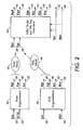
The Segment Module takes in a full color input image to be segmented and
produces three separate outputs for the three MRC planes: the Foreground FGD,
Background BGD, and Selector Sel planes, as well as several additional signals. A
block diagram of the Segment Module is shown in FIG. 2. The Segment Module is
composed of two stages: a Segmentation stage 24, followed by an MRC Scale and
Tile Tag Generation stage 44. The Segmentation stage 24 can operate in one of two
mutually exclusive modes: Scan Segmentation 24 or PDL Segmentation 26.
The primary input to the Scan Segmentation Module 24 is Src 20. It also
utilizes an 8-bit screen magnitude estimate signal SCM 22, which is further detailed
in Applicant's pending application D/A3011. The Scan Segmentation Module 24
outputs the full-color (raw) Foreground and Background planes Fgr 30 and Bgr 28,
and (possibly super sampled) Sel 32, which is exported by the module 24.
In PDL mode 40, the PDL Segmentation Module 26 does not use SCM 22,
but instead may use the signal Rht 34, which captures hint information from the PDL
interpreter and will be encoded into a CEF Hint plane Hnt 38. The output from the
PDL Segmentation Module 26 includes the full-color (raw) Foreground and
Background planes Fgr 30 and Bgr 28, the binary Selector plane Sel 32, and
possibly the Hint plane Hnt 38 when hints are present. As indicated above, the Hint
plane can be 1-bit or 8-bit deep.
The Src 20 image for Scan mode 42 and PDL mode 40 typically have been
processed differently. The Scan Segment Module 24 relies on the input being de-screened.
This is not required for the clean, noise free images directly generated
from PDL sources.
For Scan processing, the chroma components of the source input image Src
20, are assumed to be sub-sampled by a factor of 2 in the fast scan (x) direction
(XCSS). None of the color images produced by the segmentor will use XCSS. When
the chroma samples of the source image are accessed, no 'adjustment' filtering is
required. That is for the 4 sample XCSS quad: L0A0L1B1; pixel 0 is L0A0B1 and pixel 1
is L1A0B1.
The Selector plane Sel output is binary (1 bit deep), and the packed Selector
plane Spk packs together 2x2 binary neighboring Selector pixels (4 bits).
For PDL processing, the source input Src 20 is assumed to be a full-color
image where the chroma channels are typically not sub-sampled, and therefore are
at the same resolution as the luminance channel.
In general, the exported Foreground, Background, and Selector planes could
all be at different resolutions relative to the input image. For example, the
Foreground and Background planes are typically down-sampled while the Selector
plane may be up-sampled from the original input resolution. The amount of up or
down sampling is programmable under software control.
The MRC Scale and Tile Tag Generation Module 44 reads in the initial (raw)
Background Bgr 28, Foreground Fgr 30, Selector Sel 32, and the optional Hints Hnt
38 if any exist (PDL mode only). It produces the final color MRC layers: Background
Bgd 46 and Foreground Fgd 48, by subsampling and filling in the 'holes' or
previously unassigned pixels in the raw images. In addition, the MRC Scale and Tile
Tag Generation Module 44 generates four associated Tile Tag signals for the
Background Ttb 50, Foreground Ttf 52, Selector Tts 53, and optional Rendering
Hints Tth 54 if any exist (PDL mode only). The Tile Tag is one binary bit per tile (or
strip) indicating whether the current tile may be altogether omitted. This further
reduces the overall file size. Missing tiles are automatically filled to pre-defined
default color for each plane.
The Scan Segmentation Module 24 is responsible for performing the MRC
segmentation into three planes in the case of scanned documents. The inputs to the
Scan Segmentation Module include the input color signal Src 20 and the 8-bit screen
magnitude estimate signal SCM 22. The Scan Segmentation Module 24 outputs the
full-color (raw) Foreground and Background planes Fgr 28 and Bgr 30, and the
Selector Sel 32 plane.
The block diagram of the Scan Segmentation Module 24 is shown in FIG. 3.
The following is a brief description of the various modules comprising the Scan
Segmentation Module 24. The color input signal Src 20 is forwarded to the
Dependent Min-Max Module 60, which searches in a 7x7 window centered on the
current pixel of interest for the minimum Min and maximum Max color values for
dynamic thresholding.
The minimum Min 61 and maximum Max 63 values are forwarded to the
Dynamic Threshold Module 62 and the Scan MRC Separation Module 64. The
Dynamic Threshold Module 62 also uses the input color image Src 20 and the 8-bit
Screen Magnitude estimate signal SCM 22. A Dynamic Threshold Module 62
outputs the monochrome 8-bit signal Grr 55, the biased zero crossings of which
represent the locations of edges in the Selector planes. In addition, The Dynamic
Threshold Module 62 also generates an 8-bit segmentation enhancement control
Enh 59, which is used to communicate to the Scan MRC Separation Module 64, on a
pixel-by-pixel basis, if segmentation is to be applied, and if so, how much additional
enhancement to apply.
The purpose of the Block Smoothing Unit 56 is to move weak (a.k.a. false)
edges away from strong edges to prevent high contrast transitions within the
Foreground and Background JPEG minimum coded unit (MCU) blocks. If there are
no strong edges nearby, the weak edges are pushed out of the JPEG block to the
boundary between neighboring blocks. This process eliminates unnecessary sharp
transitions within JPEG blocks, thereby increasing the overall compression and
quality. The output from the Block Smoothing Unit 56 is an 8-bit smoothed Grs 57
signal, which represents a smoothed (filtered) version of the incoming signal Grr 55.
The Foreground Erosion Unit 200 is used to meet thin (but unbroken) text
requirements using linear YCC segmentation. A fixed value is subtracted from the
gray selector, thereby thinning/eroding the foreground. This is only done if a
neighborhood test verifies that the thinning won't result in broken lines, as will be
more fully described below. The output is a smoothed Gre 202 signal or the Grs 57
signal.
The Binary Scale Unit 66 provides the capability to super-sample the resulting
smoothed gray selector signal Grs 57 from the Block Smoothing 56 output. In the
normal 1:1 mode, the Grs 57 signal is threshold to produce the binary Selector plane
output Sel 32. However, for high-quality text and line-art reproduction, the Selector
plane may be super-sampled at twice the input resolution (e.g., at 1200 dpi for a 600
dpi input). The super-sampling of the Selector signal is done by doubling the
sampling frequency prior to thresholding. The resulting binary Selector pixels at the
higher resolution are packed, four neighbors at a time, into the packed Selector
signal Spk 122.
The Mark Edge Processing Module 58 takes in the packed high resolution
Selector output Spk 122 and counts the number of on and off pixels in a 5x5 [high-resolution]
window centered on the current [low-resolution] pixel of interest. The
output from the Mark Edge Processing Module 58 is the two-bit signal See 142. The
See signal 142 is set to 0 if all of the input pixels inside the 5x5 window are off
(corresponding to a 3x3 constant background area). Similarly, the See signal 142 is
set to 3 if all of the input pixels inside the window are on (corresponding to a 3x3
constant foreground area). In addition, the See output is set to 1 or 2 if the 5x5
window is mostly background or mostly foreground, respectively.
Finally, the Scan MRC Separation Module 64 takes in the full color source
signal Src 20 to be segmented as well as the color minimum and maximum (Min,
Max) from the Dependent Min-Max Module 60. In addition, the MRC Separation
Module 24 uses the See signal 142 from the Mark Edge Processing Module 58, and
the segmentation and enhancement signal Enh 59 from the Dynamic Threshold
Module 62. The MRC Separation Module 64 actually produces the two full-color
outputs Fgr 24 and Bgr 30 as the rough estimates of the Foreground and
Background planes, respectively. The various modules of the Scan Segmentation
Module will now be further described below.
A block diagram of the Dependent Min-Max Module is shown in FIG. 4. The
Dependent Min-Max Module 60 inputs the Src signal 20 and examines a 7x7 window
centered on the pixel of interest 80 to find the max L and min L pixels, L being the
luminance channel. The Max output 68 is the pixel that has the max L 72. The Min
output 70 is the pixel that has the min L 74. The resulting chroma values are
therefore dependent on the locations of where the extreme luminance values were
found.
The operation of the Dependent Min-Max Module 60 is illustrated in FIG. 5.
The operation proceeds in two steps. In the first step, the Dependent Min-Max
Module 60 searches across the window for the largest 68 and smallest 70 samples
of the luminance component L. Once the locations of the minimum 74 and maximum
luminance 72 values are found, they are output along with the chroma components
(A,B) at these locations. Even though the Src signal 20 arrives at this module with X
subsampled chroma components, this is the point at which the X chroma
subsampling ceases. That is, the Max and Min color signals do not have X sub-sampled
chrominance.
This filtering operation is separable. For instance the Min/Max of individual
columns can be computed first, and then the final Min 74 can be computed by finding
the column Min pixel that has the minimum L. This means that the incremental work
required as the window in stepped across the Src image amounts to computing one
7 high column and one 7 wide row for both the Min and the Max outputs.
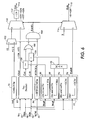
Referring to FIG. 6, the Dynamic Threshold Module 62 applies adaptive
thresholding to the incoming color source signal Src 20 to generate a raw signed 8-bit
gray selector signal Grr output 114, whose zero crossings represent the
transitions of the Selector plane. Gray selector values >= 0 mark pixels which will
have selector values of 1 and be placed in the foreground. Gray selector values <0
mark pixels which will be placed in the background. As shown in FIG. 6, the
Dynamic Threshold Module 60 utilizes the pair of dependent min/max values (Min,
Max) 90 and 92 respectively from the Dependent Min-Max Module 60, as well as the
8-bit screen magnitude estimate signal Scm 22 from the Screen Estimation Module
(SEM). The Dynamic Threshold Module 62 also produces the 8-bit signal Enh 118.
The Enh signal 118 is communicated to the Scan MRC Separation Module 64 to
determine how much enhancement to apply as pixels are placed in the background
and/or foreground planes.
The Dynamic Threshold Module 62 operates in three segmentation modes:
dynamic threshold; static threshold and force-to-foreground. Static thresholding is
applied when the image is smooth (unchanging). In this mode, pixels with luminance
values greater-than-or-equal-to DefaultThr 76 are assigned to the background
(Grr==127 = -1) and pixels with luminance values less than DefaultThr are assigned
to the foreground (Gr==129 = +1). Note 127 and 129 (+-1) represent small
magnitude values for Grr 114. These represent Weak decisions, which may be
modified by the subsequent Block Smoothing module 56 by taking into account the
position and polarity of nearby Strong decisions. A Strong decision is represented
by a signed Grr magnitude >1 (a coded value <127 or > 129). Strong decisions are
only produced in the Dynamic thresholding mode and only Strong decisions may
have non-zero Enh codes. Both Static thresholding and force-to-foreground modes
only produce Weak decisions.
In some configurations, Force-to-foreground mode is enabled for halftone
images; the mode is enabled by setting HTFGScmThr 84 to some value less than
256. Whenever Scm 22 is equal-to-or greater-than HTFGScmThr 84, Grr 114 is
forced to the minimal foreground value of 129 (= +1) and Enh 118 is set to zero.
When Force-to-foreground does not override, segmentation actively switches
between producing weak static threshold decisions and Strong dynamic threshold
decisions. The signal EnhEn indicates a Strong decision and gates the output of the
EhFVsScm function to Enh. The EhFVsScm function uses the screen magnitude
estimate Scm as the domain variable. When true, EnhEn also selects the signed 8
bit signal GSel as the source for coding Grr. GSel, described in more detail below, is
the primary output of the Dot Product module. As shown in FIG. 6, when Force-to-foreground
(HTFGEn) does not override, the two other outputs of the Dot-Product
unit Ccc and Cc0 (described below) are tested, and the results are ORed together to
compute EnhEn.
If Ccc is >= the output of the EhClrConThrVsMin function then EnhEn is
enabled. Else if Cc0 >= the maximum of the EhLumConThrVsMax function and the
EhLumConThrVsScm function then EnhEn is enabled. The input signals for the
EhClrConThrVsMin and EhLumConThrVsMax functions are the luminance
components of the Min and Max signals respectively. The input signal for the
EhLumConThrVsScm function is Scm.
The Dot Product Unit
82 (second block on the top left in
FIG. 6) uses the full-color
input signal Src 20 as well as the full-
color minimum 92 and maximum
90
values (Min, Max) from the Dependent Min and Max Unit. These values represent
the extreme luminance values, and corresponding chroma values, found within the
(7 x 7) window centered on the current pixel of interest. The operation of this block is
primarily performing the dot-product multiplication of two vectors:
GSel = min(127, max(-127 (< X , Y > /256) ));
Where < X , Y > is a dot-product operation between the two vectors X and Y:
<X, Y> = (XL, XA, XB) (YL, YA, YB)t = XL YL + XA YA + XB YB ;
where
and
As an embodiment for further improvement, when L
MN ==0 the value of the
luminance component in equation (4) changes from L
MX/2 to L
MX/4. This is a first
order attempt to adjust for a luminance-undershoot typically produced by previous
sharpening stage. This helps prevent thin text features from becoming enlarged by
the segmentation process.
The (L, A, B) values in equation (4) or (5) are the corresponding color
components of the incoming signal Src 20. The X vector in equation (3) is the vector
difference between the maximum and minimum values of (Min, Max). The Y vector in
equation (4) is the incoming signal Src 20 minus the min and max average. By
taking the dot product of these two vectors, the output is proportional to the relative
distance from the plane, which is perpendicular to the X vector and crosses it
halfway along. Note that {XA, XB, YL, YA, YB} as well as the final output GSel may be
negative. Since the absolute magnitude of the dot product output in equation (1) is
not as important as identifying zero crossings, the result is simply divided by 256
(shift right by 8) to scale it back to fit the 8-bit range. (Dot product normalization
would require dividing by the vector magnitudes). However, since the output may still
occasionally overflow the 8-bit range (by a factor of roughly 3, or 1.5 bits at most), it
is necessary to add logic to limit the output magnitude to 127 if it ever gets too large.
The Dot Product 82 output is indicated as the signed 8-bit signal GSel or Gray
Selector output in FIG. 6. To limit the size of the dot product multiplier to 8 bits, the
components of both X and Y may be pre-scaled by 1/2 and the final divisor changed
to 64.
The Dot Product Unit 82 also outputs two 8-bit signals that measure the
luminance and chroma contrast magnitude. The luminance portion Cc0 106, is
represented by the first component of the vector X:
Cc0 = XL = LMAX - LMIN
A scalar measure for the overall chroma contrast magnitude Ccc 104 is also
generated by adding together the absolute values of the two chroma-components of
the vector X.
Ccc = |XA| + |XB| eq
The absolute value over the luminance component can be ignored since L is
confined to the positive range [0...255], and the max is always larger than the min.
The decision logic functions 91 in the left portion of FIG. 6 govern the
switching between the default and active segmentation modes. Each function is
represented by a small set of (x, y) point-pairs representing a piecewise linear
function. For x values less than the first x value, the output is the first y value. For x
values > the last x value, the output is the last y value.
The significance of the above logic is that in order to operate under active
segmentation mode, either the Dot Product luminance contrast or the Dot Product
chroma contrast must be sufficiently large. The chroma contrast must be larger than
a function of the minimum luminance found in the (7 x 7) window. Likewise, the
luminance contrast must be larger than a function of the maximum luminance found
within the same window, and, in addition, it must also be larger than a function of the
screen magnitude Scm. Before exporting, the signed gray selector output gated by
HTFGEn and EnhEn is coded as an unsigned 8 bit signal Grr 114 by adding 128.
The purpose of the Block Smoothing Unit 56 is to move weak (a.k.a. false)
edges as far away from strong edges as possible. This increases the width (reduces
the frequency) of pulses in the JPEG planes and thereby reduces the compressed
size and compression noise. If there are no strong edges blocking it, weak edges are
swept out of the block completely. If a weak edge is trapped between 2 strong
edges, it is repositioned to be half way between the two. The process also
merges/removes multiple weak edge transitions which improves compression in all 3
planes.
The input to the Block Smoothing Unit 56 is the 8-bit raw gray selector output
Grr from the thresholding process (under either active or default segmentation). The
output from the Block Smoothing Unit 56 is the 8-bit smoothed Grs signal, which
represents a smoothed (filtered) version of the input signal Grr.
The very first step in the Block Smoothing Unit 56 is to subtract the bias of
128 (toggle the msb) to make Grr' a signed number. Then, the range of (Grr- 128) is
investigated. If it equals -1 or 1, is considered to be a weak edge, BG or FG,
respectively. Anything less than -1 or above 1 is considered to be a strong BG or FG
edge, respectively.
The Block Smoothing process includes four passes over a square temporary
storage area (Tmp[sz][sz]) representing the size of a JPEG minimum coded unit
(MCU) block for the Bgd and Fgd planes. For instance, if the Bgd and Fgd are to be
subsampled by a factor of 4 for JPEG compression, and, in addition, the
chrominance components are to be subsampled an additional factor of 2, then the
MCU would be 16x16. And the Tmp block needed for this Block Smoothing algorithm
would be dimensioned: Tmp[64][64]. Implementation constraints may require this
block size to be smaller, in which case 32x32 would be acceptable. Note, the current
pipeline configuration only requires a 32x32 block since chroma sub-sampling is not
used when applying 1/4 resolution reduction.
In the first pass, the (Grr-128) pixels are processed from left to right into Tmp
where each row is independent. Whenever there are strong edges, the
corresponding Tmp location is initialized to +/-K (a predefined constant ==
2*dimension of Tmp -1). The sign is same as Grr-128. Otherwise, for weak edges,
Tmp is written with the previous Tmp value where its magnitude has been reduced
by 1. Since the first pass is moving from left to right, the previous Tmp value is the
Tmp value just to the left. The previous value of the first value in a row is defined to
be 0. Reducing the magnitude by one converts +4 to +3, -2 to -1 and 0 to 0. Also,
during this pass, an accumulation (WeakCnt) is computed of all the weak values: +1,
-1 (only where Grr is weak).
In the second pass, each row of Tmp is traversed from right to left, this time,
the magnitude reduced previous value is compared with the current value. The value
with the largest magnitude is placed in the current location. Again, the previous value
for the first value on the right is assumed to be 0. Since the rows of passes 1 and 2
are independent, pass 2 can be interleaved with pass 1. Passes 3 and 4 are the
same as pass 2 except that their directions are top to bottom and bottom to top.
After the 4th pass the final smoothed result is produced by examining Tmp. If
the Tmp value has the max magnitude (+K or -K) the value used is the original
strong edge value from Grr. Otherwise the code for weak foreground or background
(128+1 or 128-1) is used depending on whether the Tmp value is positive or
negative.
Referring to FIG. 7, the Binary Scale Module 66 converts the 8-bit grayscale
selector input Grs 120 to the binary Selector plane output Sel 32. For high-quality
text and line art, the binary Selector output Sel 32 may be kept at higher resolution
than the Src 20. For example, the current design allows the use of twice the
resolution in each direction (SEG_Sel_ScaleUp), so that for a standard 600-dpi
scanner, the output resolution of the binary Sel signal may be at 1200 dpi. The
Selector Logic Module is responsible for interpolating the gray selector Grs input to
the higher resolution and then threshold the signal to generate the binary output Sel
32. A redundant packed copy of Sel (Spk) 122 is also produced at the Src 20
resolution.
The block diagram of the Binary Scale Module 66 is shown in FIG. 8. The 8-bit
gray selector input signal Grs 120 is first interpolated in the gray domain using 2D
bilinear interpolation 124 by a factor of 2 in each direction. The output from the
bilinear interpolation is passed through the multiplexer 126 to select whether to use
the interpolated (super-sampled) Selector or the usual binary one at the same
resolution as Src. Finally, the gray output is converted to binary producing the
Selector signal Sel 32 using the threshold unit 128.
It should be noted that for the 2x interpolation-factor, the binary Sel output
data rate is twice as fast as the source signal Src in each direction. This means that
for every 8-bit input Grs sample, the Binary Scale Module produces four binary
output Sel samples. A second packed form of the Sel output (Spk) 122 is produced
in which the 4 binary selector bits are packed together as shown in FIG. 9. It is
important to note that Selector output 140 is using a vector notation to indicate the
higher output resolution. While the output is still considered to be binary (that is,
assuming the values of either 0 or 1 only), each incoming Grs input generates four
Selector bits at the output (assuming the 2x interpolation factor). The four binary
pixels are packed into the 8-bit packed Selector signal Spk 122 as shown above. If
the interpolation factor is only 1, then all four bits are the same.
Referring to FIG. 10, the Mark Edge Module 58 takes the packed form of the
high-resolution Selector Spk 122 and counts the number of on and off pixels in a 5x5
[high-resolution] window 155 centered on the current pixel 80 of interest. The output
from the Mark Edge Module 58 is the four-valued signal See 142. The See signal
142 is set to 0 if all of the input pixels inside the window are 0 (corresponding to a
constant background area). Similarly, the See signal 142 is set to 3 if all of the input
pixels inside the window are on (corresponding to a constant foreground area). In
addition, the See output 142 is set to either 1 or 2 if the content of the window is
mostly background or mostly foreground, respectively. Note that since See is only 4
values and could be coded with 2 bits.
The operation of the Mark Edge Module 58 is illustrated in FIG. 11. The
operation of the unit is as follows. The input to the Edge Processing Module 58 is the
packed binary Selector signal Spk, which is at the same resolution as Src. The Edge
Processing Module 58 maintains a 3x3-pixel context window (at the original input
resolution) centered on the current pixel of interest. Logically, the packed selector
(Spk) Selector contains four binary selector pixels for each Src resolution pixel in the
3x3-pixel window as shown in FIG. 11. The thicker lines represent the original Src
resolution, which corresponds to a 6x6-pixel context window in the high-resolution
domain. However, only the inner content of 5x5 high-resolution pixel area is used;
the shaded area in FIG. 11 is excluded from the counting.
The 5x5 high-resolution context is designed for "detecting" potential edges in
the proximity of the current pixel of interest. The window pattern uses a full context of
2 [high-resolution] pixels extending below and to the right of the current pixel, but
only one from above or on the left. Note that the unique window pattern prevents any
edge from overlapping with the neighboring pixels, that is - no potential edge
location could be detected (i.e., shared) more than once, in association with multiple
(low-resolution) pixels. The 4x4=16 possible edge locations within the current
window of interest are also indicated in FIG. 11.
The
Mark Edge Module 58 counts the number of high-resolution pixels that
are currently turned on in the 5x5 high-resolution area. This number can range from
0 to 25. It is mapped to the output signal See from the
Mark Edge Module 58 as
following:
| See = 0 | if the 5x5 count was 0 (no foreground pixels found); |
| See = 1 | if the count was in the range [1...12] (mostly background pixels); |
| See = 2 | if the count was in the range [13...24] (mostly foreground pixels); |
| See = 3 | if the count was 25 (only foreground pixels found); |
Referring once again to FIG. 3, the output signal See is forwarded to the Scan
MRC Separation Module 64. Note that the See signal is at the original input
resolution (600 dpi typical). The Scan MRC Separation Module 64 is responsible for
splitting the incoming source signal Src into the Foreground and Background planes.
The Module uses the full-color minimum and maximum (Min, Max) outputs from the
Dependent Min-Max Module, as well as the Marked Selector edge count signal See
from the Mark Edge Module. In addition, The Scan MRC Separation Module has the
capability to enhance the lifting of edges via the segmentation enhancement control
signal Enh from the Dynamic Threshold Module.
The Scan MRC Separation Module 64 outputs two full-color raw initial
estimates of the Foreground and Background outputs Fgr 30 and Bgr 28,
respectively. The follow up module, the MRC Scale and Tile Tag Generation Module,
then further processes the Fgr and Bgr to produce the final Foreground and
Background outputs Fgd and Bgd, respectively.
The Scan MRC Separation Module 64 takes in the full-color source signal Src
to be segmented and produces values for one of the Fgr and Bgr outputs, or
sometimes for both. The Scan MRC Separation Module reserves the special code of
zero luminance and chroma (L = a = b = 0) to indicate an empty (undetermined) pixel
in either the Foreground Fgr or the Background Bgr outputs. As the process
continues across the page, some of the Foreground and Background pixels will
remain undetermined. The MRC Scale and Tile Tag Generation Module will then
carefully fill in the values for these undetermined pixels to keep the compression low
and prevent additional JPEG ringing artifacts.
The Scan MRC Separation Module 64 uses the value of the Selector edge
count signal See from the Mark Edge Module to determine whether to copy
enhanced Src pixels into the Background, Foreground, or both. The decision range
is illustrated in FIG. 12. Basically, the enhanced Src pixels are copied into the
Foreground if See ≥ 1, and into the Background if See ≤ 2. Consequently, the
Foreground is marked as undefined if See==0 and the Background is marked as
undefined if See==3.
At first, the enhancement factor Enhf1 is just the signal Enh incremented by
one so the max value is 256 rather than 255:
Enhf = Enh
Enhf1 = Enhf+1
Next, define the following two full-color enhanced versions of the foreground
and background (the purpose of which will be detailed below):
enhFG = LIM [ Src + ( Min - Src) (Enhf1 / 256 ) ] ;
enhBG = LIM [ Src + ( Max - Src) (Enhf1 / 256 ) ] ;
Implementation note: When the final Bgd and Fgd outputs are either XCSS (X
Chroma Subsampled) or scaled down, enhFG and enhBG may be XCSS.
In equation (14) and (15) Src is the full-color input signal and Min and Max are
the dependent minimum and maximum color outputs from the Dependent Min-Max
Module. The limit function LIM is restricting the result to be confined to the 8-bit
range [1...255] for each of the components, thereby excluding the special code of
zero that is reserved for marking undefined pixels. Note that since Src and Min and
Max are all full-color (L, A, B) vectors, the operations are in 3D space.
For the case where the Foreground is defined, that is - when See = {1, 2 or 3}
the output Fgr value is determined to be:
Fgr = enhFG, When SEE = {1, 2, 3};
Fgr = 0 if SEE = 0 ;
When the Foreground is not used (i.e., See = 0), the Foreground value is
marked as undetermined by setting its value to the special code Fgr = 0 (for all of the
three components), per equation (16). Note: The implementation extends Enhf to a
9-bit representation and its value is incremented by 1 (Enhf1) to allow normalization
by 256 instead of 255.
A close examination of equation (14) reveals that the output Foreground Fgr
value is interpolated (in 3D space) between the current input signal value Src and
the minimum value Min of the Dependent Min-Max Module, depending on the
amount of segmentation enhancement expressed by Enhf1. When Enhf = 0, no
enhancement will be done and the output will be set to the input signal Fgr = Src.
This would be the common case unless there would be sufficient contrast activity in
the (7 x 7) window. When Enhf1 = 256 (maximum enhancement), the output will be
set to the minimum signal Fgr = Min. This would normally represent the case of a
pixel in the immediate vicinity of an edge, where it would be advantageous to
enhance the edge by painting the Foreground darker as much as possible - as given
by the minimum value in the neighborhood (0=black). In general, however, the
amount of segmentation enhancement Enhf can vary between the above two
extremes, and the output Foreground values will be correspondingly weighted
between the Src and Min values.
Similarly, for the case of using the Background during segmentation, that is -
when See = {0, 1, 2}, the output Bgr value is determined by:
Bgr = enhBG when See = {0, 1, 2}
Bgr = 0 if See = 3
Like before, the output Bgr value will vary between the input Src and Max
values in proportion to the amount of segmentation enhancement Enhf1, as given by
equation (15). Equation (18) is similar to (16), with the exception of using the
maximum Max instead of the minimum Min, and the different range of See. The use
of Max for the Bgr output will make it become lighter rather than darker as was the
case for the use of Foreground.
Also, as indicated by equation (19) and corresponding with (17), when the
Background or Foreground are not used (i.e., See = 3); (see = 0) respectively or
Background value is marked as undetermined by setting its value to the special code
Bgr = 0 (for all of the three components)
The output from the MRC Separation Module is the two partially filled full-color
planes Fgr and Bgr. Away from the Selector plane edges, typically only one of the
Foreground or Background outputs will contain the current pixel [enhanced] color -
depending on whether it was light or dark. But near edges, however, information
might be carried in both the Foreground and Background channels simultaneously.
Referring to FIG. 2 the PDL MRC Segmentation Module 26 is responsible for
performing the MRC segmentation into three planes in the case of PDL documents.
The inputs to the PDL MRC Segmentation Module 26 include the input color signal
Src 20 and any Rendering Hints Rht 34 that may be supplied from the PDL
decomposer.
The PDL MRC Segmentation Module 26 outputs the full-color Foreground and
Background planes Fgr 28 and Bgr 30, the binary Selector plane Sel 32, and
possibly preserve some of the PDL hints in the 8-bit Hint plane Hnt.
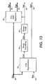
The block diagram of the PDL MRC Segmentation Module 25 is shown in
FIG. 13. Starting from the left, the PDL Segmentor reads in the input color signal Src
20 and 8-bit rendering hints Rht 34 from the PDL interpreter. The PDL Segmentor
26 produces the 8-bit gray selector signal Grr that is similar in function to that used
by the Scan processing. In addition, the PDL Segmentor outputs some of the PDL
hints as MRC hints Hnt.
The gray selector signal Grr from the PDL MRC Segmentation Module 25 is
processed through the Block Smoothing Unit 56 to create the smoothed gray
selector signal Grs, which is forwarded to the Binary Scale Unit 66. The Binary Scale
Unit 66 thresholds the Grs signal to create the binary Selector signal Sel. Since the
quality of PDL data is not improved by super-sampling the selector produced by the
Binary Scale unit is always at the Src resolution. The operation of the Block
Smoothing Unit and Binary Scale Unit is described above, respectively.
Finally, the PDL MRC Separation Module 25 is responsible for splitting the
incoming source signal Src 20 into the Foreground and Background planes Fgr 30
and Bgr 28, respectively. The separation is based on the binary Selector plane Sel
32.
The PDL Segmentation Module 26 is responsible for taking in the input color
signal Src 20 and generating the 8-bit gray selector signal Grr 66. In addition, the
PDL Segmentation Module 26 preserves some of the 8-bit PDL interpreter hints Rht
as 8-bit MRC hints Hnt on the Hint plane.
The operation of the PDL Segmentation Module is different than the Scan
processing described above. The Scan segmentation process is based on the
dependent min/max analysis followed by dynamic thresholding. However, for clean
PDL data, the segmentation is based on the classification of the content of the pixels
in a 3x3 window centered on the current pixel of interest. The classification is
prioritized as a set of rules that determines whether the current pixel is associated
with the Foreground Fgr or Background Bgr planes.
For each incoming Src pixel, the content of the 3x3 window around this pixel
is analyzed and classified into one or more of the following classes 158 shown in the
table of FIG. 14. The 3x3 window tests are prioritized as shown in the leftmost
column in FIG. 14. The smaller numbers indicate higher priority. Thus, for example,
a center pixel that is tagged by the PDL interpreter to be an Image pixel, takes
precedence (highest priority) over any other combination such as the center pixel
being black, white, or tagged as text.
The second column in the Table of
FIG. 14 lists the class name in the C code
simulation. The third column provided a brief description for the meaning of the class
and how it is tested. Finally, the last column shows how the class is associated (that
is ― segmented) into the Foreground or Background planes. The one exception to
the 3x3 window testing is the case of
classes 6 and 7. The processing for these
classes is as following:
The PDL separation Module is responsible for splitting the incoming source
signal Src into the Foreground and Background planes Fgr and Bgr, respectively.
The separation is based on the binary Selector plane Sel. The separation process
begins by initializing the foreground and background planes with the special
reserved code of zero (L = a = b = 0 ) to indicate non-used pixels
Next, the incoming color Src values are moved away from zero to prevent
confusion with the special reserved code of "not used":
Val = Max (1, Src) ;
The Max function ensures than Val is never zero in any of its planes. The Separation
process continues in a straightforward manner:
If ( Sel = 1) then Fgd = Val ; else Bgd = Val ;
That is, each incoming color pixel is placed in either the Foreground or
Background. Unlike the case of scanned documents, the information is never placed
into both planes, not even in the neighborhood of edges. Thus the separation
scheme is much simplified relative to the Scan case.
Referring to FIG. 15, the MRC Scale and Tile Tag Generation Module applies
additional processing on the rough Foreground and Background estimates Fgr and
Bgr to generate the final Foreground and Background outputs Fgd and Bgd. The
processing done by the MRC Scale and Tile Tag Generation Module is to first sub-sample
the Foreground and Background values while ignoring undefined pixels. Next
it sub-samples this result by a factor of 8 to compute a block average (again ignoring
undefined pixels). The 3rd step is to insert the computed block average into
undefined pixels. The aim is to reduce JPEG compression ringing artifacts by filling
in the undefined pixels with the block average.
An additional logic inside the MRC Scale and Tile Tag Generation Module
also monitors the Foreground and Background output values to detect and flag
constant all-black or all-white tiles. Similar logic detects when the selector and hint
are all zero. A block diagram of the MRC Scale and Tile Tag Generation Module is
shown in FIG. 17.
All four instances of the subsampling module operate in a similar way. The
sum of all pixels in an NxN area is computed while keeping a separate count of the
number of pixels which are valid=notZero. The sum is then normalized by the count
of valid pixels to produce the output. The first stage of subsampling is typically over a
4x4 area representing the overall degree of sub-sampling of the Fgd and Bgd. The
amount of subsampling is specified by the parameters: Seg_Fgd_ScaleDn,
SEG_Bgd_ScaleDn, SEG_Fgd_Dst_Css, SEG_Bgd_Dst_Css
The Css parameter controls whether the chroma samples are additionally
subsampled by a factor of 2. The second stage always sub-samples over an 8x8
area representing the JPEG block size at the subsampled resolution. The final
normalization of the subsampled output is dependent on the value of the total weight.
However, it is still possible to avoid the division operation in equation by using a
predetermined multiplication table with multiple choices for the possible total weight
values.
The Fill In Blocks insert the block averages Fga and Bga into Fgx and Bgx
replacing all undefined pixels and producing the final foreground Fgd and
background Bgd signals. The Fill In Blocks also produce a very low bandwidth
outputs Tgb/Tgf of one bt per tile or strip which can be used to optimize the
compression when CEF files are exported. Each Fill In block monitors each pixel in a
tile, testing whether all pixels are within limits set for the luminance and chrominance
samples. If all tile pixels pass all the tests then the tile tag bit is set. Each pixel has 3
tests performed:
| LumRef-L | <= TileLumErr {where LumRef is 255 for Bgd and 0 for Fgd} |
| abs(128-A) | <= TileChrmErr |
| abs(128-B) | <= TileChrmErr |
The Sel and Hnt Tile Tag modules are nothing more than the equivalent of large
NOR gates operating over one tile block. They produce a 1 if all the binary pixels in
a tile are 0. The tile sizes are programmable, but typical values vary from 64 x 64 to
512 x 512 pixels.
Referring once again to FIG. 3, the Foreground Erosion Unit 200 is used to
meet thin (but unbroken) kanji requirements using linear YCC segmentation. A fixed
value is subtracted from the gray selector, thereby thinning/eroding the foreground.
In cases where the pixel would be converted from foreground to background, this is
only done if a neighborhood test verifies that the thinning won't result in broken lines.
Referring to FIG. 16, a diagram illustrates the operation for this module 200. The
Foreground Erosion Unit 200 attempts to match a couple of templates. If a match is
found, then the
adjustment is performed. FIG. 16 shows the 2 patterns. Hatched block 210
represents Background and hatched block 214 represents Strong Foreground that is
larger than the adjustment. Hatched block 216 represent Weak Foreground that will
change to background if the adjustment is subtracted. Blocks 212 are unspecified.
The Weak Foreground 216 is only allowed to switch to Background 210 if one of the
two patterns shown in FIG. 16 matches (each has 4 possible orientations).