EP1494361A1 - Communication apparatus - Google Patents
Communication apparatus Download PDFInfo
- Publication number
- EP1494361A1 EP1494361A1 EP02718542A EP02718542A EP1494361A1 EP 1494361 A1 EP1494361 A1 EP 1494361A1 EP 02718542 A EP02718542 A EP 02718542A EP 02718542 A EP02718542 A EP 02718542A EP 1494361 A1 EP1494361 A1 EP 1494361A1
- Authority
- EP
- European Patent Office
- Prior art keywords
- transmit signal
- electric power
- switching
- unit
- communication apparatus
- Prior art date
- Legal status (The legal status is an assumption and is not a legal conclusion. Google has not performed a legal analysis and makes no representation as to the accuracy of the status listed.)
- Withdrawn
Links
Images





Classifications
-
- H—ELECTRICITY
- H04—ELECTRIC COMMUNICATION TECHNIQUE
- H04W—WIRELESS COMMUNICATION NETWORKS
- H04W52/00—Power management, e.g. Transmission Power Control [TPC] or power classes
- H04W52/04—Transmission power control [TPC]
- H04W52/52—Transmission power control [TPC] using AGC [Automatic Gain Control] circuits or amplifiers
-
- H—ELECTRICITY
- H03—ELECTRONIC CIRCUITRY
- H03F—AMPLIFIERS
- H03F1/00—Details of amplifiers with only discharge tubes, only semiconductor devices or only unspecified devices as amplifying elements
- H03F1/02—Modifications of amplifiers to raise the efficiency, e.g. gliding Class A stages, use of an auxiliary oscillation
- H03F1/0205—Modifications of amplifiers to raise the efficiency, e.g. gliding Class A stages, use of an auxiliary oscillation in transistor amplifiers
- H03F1/0277—Selecting one or more amplifiers from a plurality of amplifiers
-
- H—ELECTRICITY
- H03—ELECTRONIC CIRCUITRY
- H03G—CONTROL OF AMPLIFICATION
- H03G1/00—Details of arrangements for controlling amplification
- H03G1/0005—Circuits characterised by the type of controlling devices operated by a controlling current or voltage signal
- H03G1/0088—Circuits characterised by the type of controlling devices operated by a controlling current or voltage signal using discontinuously variable devices, e.g. switch-operated
-
- H—ELECTRICITY
- H03—ELECTRONIC CIRCUITRY
- H03G—CONTROL OF AMPLIFICATION
- H03G3/00—Gain control in amplifiers or frequency changers
- H03G3/20—Automatic control
- H03G3/30—Automatic control in amplifiers having semiconductor devices
- H03G3/3036—Automatic control in amplifiers having semiconductor devices in high-frequency amplifiers or in frequency-changers
- H03G3/3042—Automatic control in amplifiers having semiconductor devices in high-frequency amplifiers or in frequency-changers in modulators, frequency-changers, transmitters or power amplifiers
-
- H—ELECTRICITY
- H03—ELECTRONIC CIRCUITRY
- H03F—AMPLIFIERS
- H03F2203/00—Indexing scheme relating to amplifiers with only discharge tubes or only semiconductor devices as amplifying elements covered by H03F3/00
- H03F2203/72—Indexing scheme relating to gated amplifiers, i.e. amplifiers which are rendered operative or inoperative by means of a control signal
- H03F2203/7239—Indexing scheme relating to gated amplifiers, i.e. amplifiers which are rendered operative or inoperative by means of a control signal the gated amplifier being switched on or off by putting into parallel or not, by choosing between amplifiers and shunting lines by one or more switch(es)
-
- H—ELECTRICITY
- H04—ELECTRIC COMMUNICATION TECHNIQUE
- H04B—TRANSMISSION
- H04B1/00—Details of transmission systems, not covered by a single one of groups H04B3/00 - H04B13/00; Details of transmission systems not characterised by the medium used for transmission
- H04B1/02—Transmitters
- H04B1/04—Circuits
- H04B2001/0408—Circuits with power amplifiers
- H04B2001/0416—Circuits with power amplifiers having gain or transmission power control
Definitions
- the present invention relates to a communication apparatus that adjusts the electric power of a transmit signal according to communication environments.
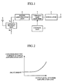
- Fig. 1 is a block diagram showing a prior art communication apparatus.
- reference numeral 1 denotes an input terminal for receiving a transmit signal
- reference numeral 2 denotes a modulator for modulating the transmit signal input thereto via the input terminal
- reference numeral 3 denotes a variable gain amplifying unit having a power gain which is set by a control unit 7, for adjusting the electric power of the transmit signal modulated by the modulator
- reference numeral 4 denotes a power amplification unit for amplifying the electric power of the transmit signal output thereto from the variable gain amplifying unit 3
- reference numeral 5 denotes an antenna sharing unit for outputting the transmit signal output thereto from the power amplification unit 4 to an antenna 6 and for outputting a received signal received by the antenna 6 to the power amplification unit 4
- reference numeral 6 denotes the antenna of the communication apparatus
- reference numeral 7 denotes the control unit for controlling the power gain of the variable gain amplifying unit 3.
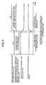
- Fig. 2 is a graphical representation showing a relationship between the level of the output of the power amplification unit 4 and the consumed electric current of the power amplification unit 4.
- the description is directed to a case where the communication apparatus is installed in a mobile station and transmits information to a base station.
- the modulator 2 When a transmit signal is input, via the input terminal 1, to the communication apparatus, the modulator 2 modulates the transmit signal in order to convert the transmit signal into a signal suitable for wireless communications.
- variable gain amplifying unit 3 adjusts the electric power of the modulated transmit signal under the control of the control unit 7 so that the modulated transmit signal has desired electric power.
- the power amplification unit 4 When then receiving the transmit signal from the variable gain amplifying unit 3, the power amplification unit 4 amplifies the electric power of the transmit signal and outputs it to the antenna sharing unit 5. As a result, the transmit signal is transmitted to the base station by way of the antenna 6.
- the communication apparatus installed in the mobile station generally adjusts the electric power of the transmit signal according to the distance to the base station and propagation environments, the communication apparatus is rarely used at a maximum output level, and, when the transmit signal has low electric power, is frequently used at about certain output levels which make the consumed electric current of the power amplification unit 4 become constant (see Fig. 2).
- a prior art communication apparatus provided with a bypass circuit for delivering a transmit signal output from a variable gain amplifying unit 3 directly to an antenna sharing unit 5 without delivering the transmit signal to a power amplification unit 4, for turning off the power supply of the power amplification unit 4 when the transmit signal has low electric power in order to reduce the consumed electric current effectively is disclosed by Japanese patent application publication No. 9-148,852.
- the prior art communication apparatus constructed as mentioned above can turn off the power supply of the power amplification unit 4 and can reduce the consumed electric current when the transmit signal has low electric power, steep changes in the electric power of the transmit signal can occur when switching from a route passing through the power amplification unit 4 to another route passing through the bypass circuit, or when switching from the other route passing through the bypass circuit to the route passing through the power amplification unit 4.
- a problem with the prior art communication apparatus is therefore that the band width of the transmit signal increases and this results in interference with other communication links.
- the present invention is made in order to solve the above-mentioned problem, and it is therefore an object of the present invention to provide a communication apparatus that can reduce steep changes in the electric power of a transmit signal, thereby reducing the consumed electric current with no degradation in the communication performance.
- a communication apparatus in accordance with the present invention includes a preset control procedure for changing the electric power of a transmit signal and a control means for controlling an electric power adjustment means, a power amplification means, and a switching means according to the control procedure.
- the present embodiment offers an advantage of being able to prevent steep changes in the electric power of the transmit signal, thereby reducing the consumed electric current without degradation in the communication performance.
- control means allows the switching means to change a destination of delivery of the transmit signal from the bypass means to the power amplification means, and also allows the power amplification means to amplify the transmit signal after reducing a power gain of the electric power adjustment means.
- the present embodiment offers an advantage of being able to prevent steep changes in the electric power of the transmit signal from occurring when raising the electric power of the transmit signal.
- control means allows the switching means to change the destination of the delivery of the transmit signal from the power amplification means to the bypass means after prohibiting the power amplification means from amplifying the transmit signal.
- the present embodiment offers an advantage of being able to prevent steep changes in the electric power of the transmit signal from occurring when lowering the electric power of the transmit signal.
- the power amplification means is comprised of a variable gain amplifying unit and the bypass means is comprised of a variable gain amplifying unit.
- the present embodiment offers an advantage of being able to significantly reduce the dynamic range of the electric power adjustment means.
- control means gradually changes the electric power of the transmit signal when allowing the switching means to change the destination of the delivery of the transmit signal.
- the present embodiment offers an advantage of being able to effectively prevent steep changes in the electric power of the transmit signal from occurring when changing the electric power of the transmit signal.
- a communication apparatus in accordance with the present invention includes a control means for, when causing a switching means to change a destination of delivery of a transmit signal, checking a format of the transmit signal, determining a switching time when switching the destination of the delivery of the transmit signal according to the format, and causing the switching means to change the destination of the delivery of the transmit signal at the determined switching time.
- the present invention offers an advantage of being able to reduce the consumed electric current without causing losses in important data which cause big trouble in communications.
- the control means when causing the switching means to change the destination of the delivery of the transmit signal, transmits a request for change of the format of the transmit signal.
- the present invention offers an advantage of being able to reduce the consumed electric current without causing losses in important data which cause big trouble in communications.
- a communication apparatus in accordance with the present invention includes a phase correction means for correcting a phase of a transmit signal output to an electric power adjustment means when a switching means changes a destination of delivery of the transmit signal.
- the present invention offers an advantage of being able to reduce the consumed electric current without causing losses in important data which cause big trouble in communications because phase correction means can reduce changes in the phase of the transmit signal which are incident to the route switching.
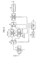
- Fig. 3 is a block diagram showing the structure of a communication apparatus in accordance with embodiment 1 of the present invention.
- reference numeral 11 denotes an input terminal for receiving a transmit signal
- reference numeral 12 denotes a modulator for modulating the transmit signal input thereto via the input terminal
- reference numeral 13 denotes a variable gain amplifying unit (i.e., an electric power adjustment means) having a gain which is set by a control unit 19, for adjusting the electric power of the transmit signal modulated by the modulator
- reference numeral 14 denotes a high-frequency selection switch for delivering the transmit signal output thereto from the variable gain amplifying unit 13 under the control of the control unit 19 to either a route A or another route B
- reference numeral 15 denotes a power amplification unit (i.e., a power amplification means) disposed on the route A, for amplifying the electric power of the transmit signal output thereto, via the high-frequency selection switch, from the variable gain amplifying unit 13.
- the power amplification unit 15 is comprised of at least one amplifier.
- Reference numeral 16 denotes a switching unit for connecting the route A or B to an antenna sharing unit 17 under the control of the control unit 19.
- a switching means is comprised of the high-frequency selection switch 14 and the switching unit 16.
- Reference numeral 17 denotes the antenna sharing unit for outputting the transmit signal output thereto from the switching unit 16 to the antenna 18 and for outputting a received signal received by the antenna 18 to the switching unit
- reference numeral 18 denotes the antenna of the communication apparatus
- reference numeral 19 denotes the control unit (i.e., a control means) for reading a control procedure for changing the electric power of the transmit signal from a memory 20 so as to control the variable gain amplifying unit 13, the power amplification unit 15, the high-frequency selection switch 14, and the switching unit 16 according to the control procedure
- reference numeral 20 denotes the memory in which the control procedure for changing the electric power of the transmit signal is pre-stored.
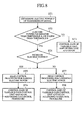
- Fig. 8 is a flow chart showing processing performed by the communication apparatus in accordance with embodiment 1 of the present invention.
- the description is directed to a case where the communication apparatus is installed in a mobile station and transmits information to a base station.
- the modulator 12 When a transmit signal is input, via the input terminal 11, to the communication apparatus, the modulator 12 modulates the transmit signal in order to convert the transmit signal into a signal suitable for wireless communications.
- variable gain amplifying unit 13 adjusts the electric power of the modulated transmit signal under the control of the control unit 19 (the operation of the control unit 19 will be explained later) so that the modulated transmit signal has desired electric power.
- the power amplification unit 15 amplifies the electric power of the transmit signal output thereto from the variable gain amplifying unit 13 and outputs it to the antenna sharing unit 17.
- the transmit signal output from the variable gain amplifying unit 13 is delivered directly to the antenna sharing unit 17.
- the transmit signal is transmitted to the base station by way of the antenna 18.
- control unit 19 the operation of the control unit 19 will be explained concretely.
- the control unit 19 determines the electric power P of the transmit signal first (in step ST1).
- the electric power P of the transmit signal can be determined by a component other than the control unit 19.
- control unit 19 After determining the electric power P of the transmit signal, the control unit 19 compares the electric power P with thresholds A and B (see Fig. 4) (in step ST2).
- the electric power of the transmit signal is adjusted by the variable gain amplifying unit 13 and the power amplification unit 15.
- control unit 19 determines the power gain of the variable gain amplifying unit 13 according to the electric power P of the transmit signal (in step ST3).
- the electric power of the transmit signal is adjusted by only the variable gain amplifying unit 13.
- step ST2 when determining that the electric power P > the threshold A, the control unit 19 reads a control procedure for raising the electric power of the transmit signal from the memory 20 (in steps ST4 and ST5).
- the control unit reads a control procedure for reducing the power gain of the variable gain amplifying unit 13, then switching from the route B to the route A, and, after that, turning on the power supply of the power amplification unit 15.
- control unit 19 outputs a switching command for selection of the route A to the high-frequency selection switch 14 and the switching unit 16 after outputting a control signal for instructing a reduction in the power gain to the variable gain amplifying unit 13.
- control unit 19 outputs a control signal for turning on the power supply of at least one amplifier to the power amplification unit 15 (step ST6).
- the control unit 19 turns on the power supply of at least one amplifier in the power amplification unit 15 after switching from the route B to the route A.
- the control unit 19 can switch from the route B to the route A after turning on the power supply of at least one amplifier in the power amplification unit 15.
- the control unit When determining that the electric power P > the threshold A and the route A has been selected the last time and until now, the control unit maintains the selection of the route A. Then, while determining the power gain of the variable gain amplifying unit 13 according to the electric power P of the transmit signal, the control unit 19 determines one or more amplifiers which are to be powered on in the power amplification unit 15. In this case, the electric power of the transmit signal is adjusted by the variable gain amplifying unit 13 and the power amplification unit 15.
- control unit 19 reads a control procedure for reducing the electric power of the transmit signal from the memory 20 (in steps ST4 and ST7).
- the control unit reads a control procedure for turning off the power supply of the power amplification unit 15, then switching from the route A to the route B, and, after that, raising the power gain of the variable gain amplifying unit 13.
- control unit 19 outputs a switching command for instructing selection of the route B to the high-frequency selection switch 14 and the switching unit 16 after outputting a control signal for turning off the power supplies of all amplifiers included in the power amplification unit 15. After that, the control unit 19 outputs a control signal for raising the power gain to the variable gain amplifying unit 13 (in step ST8).
- control means can turn off the power supplies of all amplifies included in the power amplification unit 15 and then switch from the route A to the route B.
- the control unit When determining that the electric power P ⁇ the threshold B and the route B has been selected the last time and until now, the control unit maintains the selection of the route B. Then, according to the electric power P of the transmit signal, the control unit determines the power gain of the variable gain amplifying unit 13. In this case, the electric power of the transmit signal is adjusted by only the variable gain amplifying unit 13.
- the control unit 19 is so constructed as to read a control procedure for changing the electric power of the transmit signal from the memory 20 and to control the variable gain amplifying unit 13, the power amplification unit 15, the high-frequency selection switch 14, and the switching unit 16 according to the control procedure. Therefore, the present embodiment offers an advantage of being able to prevent steep changes in the electric power of the transmit signal, thereby reducing the consumed electric current without degradation in the communication performance.
- the threshold B smaller than the threshold A, as well as the threshold A, are used, as previously mentioned. This is because the turning on and off operations of the power supply of the power amplification unit 15 are made to have hysteresis characteristics, thereby preventing frequent occurrence of route switching.
- the threshold A and the threshold B can be so set as to have an identical value.
- the two routes are provided, as previously mentioned.
- the number of routes disposed in the communication apparatus is not limited to two, and three or more routes can be provided.
- control unit controls each component in turn according to the control procedure, which is not explained above, is that changes in the gain of the communication apparatus at the time of route switching using the high frequency selection switch 14 and the switching unit 16 and changes in the amplification characteristics of the variable gain amplifying unit 13 and the power amplification unit 15 are not constant and it is impossible to control all the components simultaneously, and therefore the electric power of the transmit signal varies with time.
- Fig. 9 is a block diagram showing a communication apparatus in accordance with embodiment 2 of the present invention.
- the same reference numerals as shown in Fig. 3 denote the same components as those of embodiment 1 or like components, and therefore the explanation of these components will be omitted hereafter.
- Reference numeral 21 denotes a variable gain amplifying unit (i.e., a power amplification means) installed on a route A, for adjusting the electric power of a transmit signal output thereto from a variable gain amplifying unit 13 under the control of a control unit 19, and reference numeral 22 denotes a variable gain amplifying unit (i.e., a bypass means) installed on a route B, for adjusting the electric power of the transmit signal output thereto from the variable gain amplifying unit 13 under the control of the control unit 19.
- a variable gain amplifying unit i.e., a power amplification means
- the variable gain amplifying unit 22 can amplify the transmit signal with a gain smaller than that with which the variable gain amplifying unit 21 can amplify the transmit signal, and has a smaller amount of consumed electric current than the variable gain amplifying unit 21.
- the communication apparatus in accordance with embodiment 2 differs from that in accordance with embodiment 1 in that the variable gain amplifying unit 22 is disposed on the route B, and the variable gain amplifying unit 21 is disposed on the route A instead of the power amplification unit 15, the communication apparatus in accordance with embodiment 2 basically operates in the same way as that in accordance with embodiment 1.
- the control unit when the transmit signal has low electric power, that is, when the route B is selected by a high-frequency selection switch 14 and a switching unit 16, the control unit turns on the power supply of the variable gain amplifying unit 22 while turning off the power supply of the variable gain amplifying unit 21.
- the control unit since not only the variable gain amplifying unit 13 but the variable gain amplifying unit 22 can perform gain control, unlike the communication apparatus in accordance with above-mentioned embodiment 1, the power consumption at the time of low electric power output can be reduced and the dynamic range of the variable gain amplifying unit 13 can be significantly reduced.
- the control unit turns on the power supply of the variable gain amplifying unit 21 while turning off the power supply of the variable gain amplifying unit 22.
- the dynamic range of the variable gain amplifying unit 13 can be significantly reduced.
- the control unit 19 reads a control procedure for changing the electric power of the transmit signal from the memory 20, and controls the variable gain amplifying unit 13, the power amplification unit 15, the high-frequency selection switch 14, and the switching unit 16 according to the control procedure.
- a control unit when switching between two routes by using a high-frequency selection switch 14 and a switching unit 16, a control unit can gradually change the electric power of a transmit signal by controlling the power gain of a variable gain amplifying unit 13 and the power supply voltage of a power amplification unit 15 so that they change gently.
- the present embodiment offers an advantage of being able to, when changing the electric power of the transmit signal, prevent steep changes in the electric power of the transmit signal more effectively as compared with above-mentioned embodiment 1.
- the communication apparatus of this embodiment can prevent steep changes in the electric power of the transmit signal more effectively as compared with prior art communication apparatus when changing the electric power of the transmit signal, even though the control unit controls the variable gain amplifying unit 13, the power amplification unit 15, the high-frequency selection switch 14, and the switching unit 16 without following the preset control procedure.
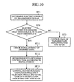
- Fig. 10 is a flow chart showing processing performed by a communication apparatus in accordance with embodiment 4 of the present invention.
- the control unit 19 reads a control procedure for changing the electric power of the transmit signal from the memory 20, and controls the variable gain amplifying unit 13, the power amplification unit 15, the high-frequency selection switch 14, and the switching unit 16 according to the control procedure.
- a control unit 19 can check the signal format of a transmit signal, determine a switching control time when route switching control is to be carried out (i.e., a time when changing the destination of the transmit signal) according to the signal format, and switch between the two routes at the switching control time.
- control unit 19 performs the above-mentioned operations.
- the transmit signal is comprised of message data, control information data about control of communications, etc., and is transmitted to the communication apparatus with two or more types of data included in the transmit signal being separated with respect to time.
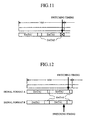
- the electric power of the transmit signal changes rapidly when the communication apparatus switches between the two routes. Therefore, as shown in Fig. 11, data contained in the transmit signal may be lost when the communication apparatus switches between the two routes.
- the lost data In a case where the lost data is important for the current communication link or the transmit signal has a little amount of information, the lost data may significantly interfere with the current communication link and the demodulation performance of the base station may degrade.
- the type of data that may be lost at the time of route switching is also identical. Accordingly, every time when the communication apparatus switches between the two routes, the same type of data may be lost and the current communication link may encounter trouble.
- the switching control timing for each slot so that switching between the two routes is carried out when transmitting data which does not cause big trouble in the communication link based on the signal format of the transmit signal on a physical channel, the degradation of the quality of the communication link can be prevented to some extent.
- control unit operates as follows.
- the control unit 19 when comparing the electric power P of the transmit signal with two thresholds A and B, and then determining that there is a necessity to switch between the two routes, as in the case of above-mentioned embodiment 1, the control unit 19 refers to format information (i.e., format information may be input, independently of the transmit signal, to an input terminal 11) indicating the signal format of the transmit signal, which is contained in the transmit signal input from the input terminal 11, and checks the signal format of the transmit signal on the physical channel (in step ST11).
- format information i.e., format information may be input, independently of the transmit signal, to an input terminal 11
- the control unit 19 grasps the location of the data2 in the checked signal format and determines the switching control time (i.e., the switching timing) so that switching Between the two routes is not carried out at the time of transmission of the data2 (in step ST12).
- control unit 19 controls the high-frequency selection switch 14 and the switching unit 16 so as to perform route switching, and also controls the gain of the variable gain amplifying unit 13 and so on (in step ST13).
- the communication apparatus is so constructed that the control unit 19 checks the signal format of the transmit signal, determines a switching control time when carrying out switching between the two routes according to the signal format, and causing the high-frequency selection switch 14 and the switching unit 16 to switch between the two routes at the switching control time. Therefore, the present embodiment offers an advantage of being able to reduce the consumed electric current without causing losses in important data which cause big trouble in the communication link.
- the control unit 19 when switching between the two routes by using the high-frequency selection switch 14 and the switching unit 16, the control unit 19 can check the signal format of a transmit signal, determine a switching control time when route switching control is to be carried out according to the signal format, and switch between the two routes at the switching control time, as previously mentioned.
- a control unit 19 when outputting a switching command for switching between two routes to a high-frequency selection switch 14 and a switching unit 16, a control unit 19 transmits a request for change of the signal format of a transmit signal to a source apparatus which has sent the transmit signal to the communication apparatus, as shown in Fig. 13, in order not to switch between the two routes when data which causes big trouble in the communication link reaches the high-frequency selection switch.
- control unit 19 switches between the two routes after the source apparatus has changed the signal format of the transmit signal.
- the control unit 19 transmits information indicating the new signal format to the base station, as shown in Fig. 14.
- the base station can surely demodulate the received signal even if the signal format of the transmit signal has been changed.
- the control unit can insert dummy data which does not affect the communication link even if the dummy data is lost, as shown in Fig. 15, into a location corresponding to the switching control time, thereby preventing the degradation of the demodulation performance of the base station.
- Fig. 16 is a block diagram showing a communication apparatus in accordance with embodiment 6 of the present invention.
- the same reference numerals as shown in Fig. 3 denote the same components as those of embodiment 1 or like components, and therefore the explanation of these components will be omitted hereafter.
- Reference numeral 23 denotes a baseband signal generator for generating a transmit signal which is a baseband signal
- reference numeral 24 denotes a phase correction unit (i.e., a phase correction means) built in the baseband signal generator 23, for correcting the phase of the transmit signal when a control unit switches between two routes by using a high-frequency selection switch 14 and a switching unit 16,
- reference numeral 25 denotes the control unit (i.e., a control means and a phase correction means) which has the same function as the control unit 19 of above-mentioned embodiment 1, and also has a function of outputting a correction command indicating a degree of phase to be corrected to the phase correction unit 24.
- Fig. 17 is a flow chart showing processing performed by the communication apparatus in accordance with embodiment 6 of the present invention.
- the control unit 25 when carrying out route switching by using the high-frequency selection switch 14 and the switching unit 16, the control unit 25 outputs a correction command indicating a degree of phase to be corrected, which corresponds to a change in the phase of the transmit signal incident to the route switching to the phase correction unit 24, and the phase correction unit 24 corrects the phase of the transmit signal according to the correction command (in step ST21).
- the communication apparatus can reduce changes in the phase of the transmit signal which are incident to the route switching.
- the communication apparatus in accordance with the present invention carries out communications smoothly while reducing its power consumption, by appropriately adjusting the electric power of a transmit signal input thereto according to the distance from a mobile station in which the communication apparatus is mounted to a base station and propagation environments, and is suitable for use in mobile stations such as mobile phones.
Landscapes
- Engineering & Computer Science (AREA)
- Power Engineering (AREA)
- Computer Networks & Wireless Communication (AREA)
- Signal Processing (AREA)
- Transmitters (AREA)
- Mobile Radio Communication Systems (AREA)
- Control Of Amplification And Gain Control (AREA)
- Tone Control, Compression And Expansion, Limiting Amplitude (AREA)
Abstract
Description
Claims (8)
- A communication apparatus including an electric power adjustment means for adjusting electric power of a transmit signal, a power amplification means for receiving the transmit signal whose electric power is adjusted by the electric power adjustment means and for amplifying the transmit signal and outputting it to an antenna, a bypass means for receiving the transmit signal whose electric power is adjusted by the electric power adjustment means and for outputting the transmit signal to the antenna, and a switching means for delivering the transmit signal output thereto from the electric power adjustment means to either the power amplification means or the bypass means,
characterized in that a control procedure for changing the electric power of the transmit signal is preset, and the apparatus comprises a control means for controlling the electric power adjustment means, the power amplification means, and the switching means according to the control procedure. - The communication apparatus according to Claim 1,
characterized in that after reducing a power gain of the electric power adjustment means, the control means allows the switching means to change the destination of the delivery of the transmit signal from the bypass means to the power amplification means, and also allows the power amplification means to amplify the transmit signal. - The communication apparatus according to Claim 1,
characterized in that after prohibiting the power amplification means from amplifying the transmit signal, the control means allows the switching means to change the destination of the delivery of the transmit signal from the power amplification means to the bypass means. - The communication apparatus according to Claim 1,
characterized in that the power amplification means is comprised of a variable gain amplifying unit, and the bypass means is comprised of a variable gain amplifying unit. - The communication apparatus according to Claim 1,
characterized in that the control means gradually changes the electric power of the transmit signal when allowing the switching means to change the destination of the delivery of the transmit signal. - A communication apparatus including an electric power adjustment means for adjusting electric power of a transmit signal, a power amplification means for receiving the transmit signal whose electric power is adjusted by the electric power adjustment means and for amplifying the transmit signal and outputting it to an antenna, a bypass means for receiving the transmit signal whose electric power is adjusted by the electric power adjustment means and for outputting the transmit signal to the antenna, and a switching means for delivering the transmit signal output thereto from the electric power adjustment means to either the power amplification means or the bypass means,
characterized in that the apparatus comprises a control means for, when causing the switching means to change the destination of the delivery of the transmit signal, checking a format of the transmit signal, determining a switching time when switching the destination of the delivery of the transmit signal according to the format, and causing the switching means to change the destination of the delivery of the transmit signal at the determined switching time. - The communication apparatus according to Claim 1,
characterized in that when causing the switching means to change the destination of the delivery of the transmit signal, the control means transmits a request for change of the format of the transmit signal. - A communication apparatus including an electric power adjustment means for adjusting electric power of a transmit signal, a power amplification means for receiving the transmit signal whose electric power is adjusted by the electric power adjustment means and for amplifying the transmit signal and outputting it to an antenna, a bypass means for receiving the transmit signal whose electric power is adjusted by the electric power adjustment means and for outputting the transmit signal to the antenna, and a switching means for delivering the transmit signal output thereto from the electric power adjustment means to either the power amplification means or the bypass means,
characterized in that the apparatus comprises a phase correction means for correcting a phase of the transmit signal output to the electric power adjustment means when the switching means changes the destination of the delivery of the transmit signal.
Applications Claiming Priority (1)
| Application Number | Priority Date | Filing Date | Title |
|---|---|---|---|
| PCT/JP2002/003631 WO2003085849A1 (en) | 2002-04-11 | 2002-04-11 | Communication apparatus |
Publications (2)
| Publication Number | Publication Date |
|---|---|
| EP1494361A1 true EP1494361A1 (en) | 2005-01-05 |
| EP1494361A4 EP1494361A4 (en) | 2006-03-01 |
Family
ID=28694871
Family Applications (1)
| Application Number | Title | Priority Date | Filing Date |
|---|---|---|---|
| EP02718542A Withdrawn EP1494361A4 (en) | 2002-04-11 | 2002-04-11 | COMMUNICATION DEVICE |
Country Status (5)
| Country | Link |
|---|---|
| US (1) | US20050090210A1 (en) |
| EP (1) | EP1494361A4 (en) |
| JP (1) | JP4044054B2 (en) |
| CN (1) | CN1623282A (en) |
| WO (1) | WO2003085849A1 (en) |
Cited By (2)
| Publication number | Priority date | Publication date | Assignee | Title |
|---|---|---|---|---|
| WO2007112256A1 (en) * | 2006-03-27 | 2007-10-04 | Shell Oil Company | Amplifier and method of amplifying an input signal |
| US8258784B2 (en) | 2007-07-03 | 2012-09-04 | Shell Oil Company | System and method for measuring a time-varying magnetic field and method for production of a hydrocarbon fluid |
Families Citing this family (8)
| Publication number | Priority date | Publication date | Assignee | Title |
|---|---|---|---|---|
| EP2136596B1 (en) * | 2004-12-24 | 2012-09-05 | Mitsubishi Electric R&D Centre Europe B.V. | Method and corresponding system for transmitting information involving enhanced allocation of spectral resources |
| US7346317B2 (en) * | 2005-04-04 | 2008-03-18 | Freescale Semiconductor, Inc. | Dynamic gain and phase compensation for power amplifier load switching |
| US8618876B2 (en) * | 2008-05-30 | 2013-12-31 | Qualcomm Incorporated | Reduced power-consumption transmitters |
| KR101689182B1 (en) * | 2010-03-04 | 2016-12-26 | 삼성전자주식회사 | Apparatus and method for transmission power control and dybamic frequency selection during movement of base statoin |
| CN103368514B (en) * | 2012-03-29 | 2017-10-24 | 北京普源精电科技有限公司 | A kind of measurement apparatus with variable gain amplifier |
| JP5958336B2 (en) * | 2012-12-28 | 2016-07-27 | 富士通株式会社 | Transmission signal power control device and communication device |
| CN104852749B (en) * | 2014-02-19 | 2018-01-16 | 华为终端(东莞)有限公司 | Radio circuit and terminal device |
| CN104901725B (en) * | 2015-05-19 | 2018-09-21 | 西安海导信息技术有限公司 | Signal transmission apparatus, locator, signal transmission system and method for transmitting signals |
Family Cites Families (14)
| Publication number | Priority date | Publication date | Assignee | Title |
|---|---|---|---|---|
| US6104934A (en) * | 1995-08-09 | 2000-08-15 | Spectral Solutions, Inc. | Cryoelectronic receiver front end |
| JPH09148852A (en) * | 1995-11-24 | 1997-06-06 | Matsushita Electric Ind Co Ltd | Variable transmission output device |
| JPH118560A (en) * | 1997-04-25 | 1999-01-12 | Matsushita Electric Ind Co Ltd | Transmission output control circuit and transmission output control method |
| JP3094955B2 (en) * | 1997-06-23 | 2000-10-03 | 日本電気株式会社 | Transmission amplifier control circuit |
| JPH11177444A (en) * | 1997-12-15 | 1999-07-02 | Matsushita Electric Ind Co Ltd | Transmission power control apparatus and method |
| JPH11274948A (en) * | 1998-03-20 | 1999-10-08 | Toshiba Corp | Transmission power control device and transmission power control unit used in this transmission power control device |
| GB9811382D0 (en) * | 1998-05-27 | 1998-07-22 | Nokia Mobile Phones Ltd | A transmitter |
| JP2000022559A (en) * | 1998-07-03 | 2000-01-21 | Nec Corp | Transmission output control circuit |
| JP3587346B2 (en) * | 1998-08-07 | 2004-11-10 | 松下電器産業株式会社 | Wireless communication device and transmission power control method in wireless communication device |
| JP2000323999A (en) * | 1999-05-13 | 2000-11-24 | Denso Corp | Transmission power control circuit |
| US6313698B1 (en) * | 1999-09-24 | 2001-11-06 | Qualcomm Incorporated | Method and apparatus for wireless phone transmit power amplification with reduced power consumption |
| JP2001111450A (en) * | 1999-10-13 | 2001-04-20 | Nec Corp | Radio communication equipment and transmission/ reception control system to be used for the same |
| US6567653B1 (en) * | 2000-04-12 | 2003-05-20 | Ericsson Inc. | Dual-mode communications transmitter |
| US6754510B2 (en) * | 2001-12-13 | 2004-06-22 | Superconductor Technologies, Inc. | MEMS-based bypass system for use with a HTS RF receiver |
-
2002
- 2002-04-11 US US10/504,598 patent/US20050090210A1/en not_active Abandoned
- 2002-04-11 WO PCT/JP2002/003631 patent/WO2003085849A1/en not_active Ceased
- 2002-04-11 JP JP2003582920A patent/JP4044054B2/en not_active Expired - Fee Related
- 2002-04-11 CN CNA028286030A patent/CN1623282A/en active Pending
- 2002-04-11 EP EP02718542A patent/EP1494361A4/en not_active Withdrawn
Cited By (4)
| Publication number | Priority date | Publication date | Assignee | Title |
|---|---|---|---|---|
| WO2007112256A1 (en) * | 2006-03-27 | 2007-10-04 | Shell Oil Company | Amplifier and method of amplifying an input signal |
| US7436334B2 (en) | 2006-03-27 | 2008-10-14 | Shell Oil Company | Amplifier, analogue to digital converter, methods of amplifying and of converting an analogue input signal to a digital output signal and of producing a mineral hydrocarbon fluid |
| AU2007230740B2 (en) * | 2006-03-27 | 2010-07-22 | Shell Internationale Research Maatschappij B.V. | Amplifier and method of amplifying an input signal |
| US8258784B2 (en) | 2007-07-03 | 2012-09-04 | Shell Oil Company | System and method for measuring a time-varying magnetic field and method for production of a hydrocarbon fluid |
Also Published As
| Publication number | Publication date |
|---|---|
| JP4044054B2 (en) | 2008-02-06 |
| EP1494361A4 (en) | 2006-03-01 |
| CN1623282A (en) | 2005-06-01 |
| US20050090210A1 (en) | 2005-04-28 |
| JPWO2003085849A1 (en) | 2005-08-18 |
| WO2003085849A1 (en) | 2003-10-16 |
Similar Documents
| Publication | Publication Date | Title |
|---|---|---|
| KR101025693B1 (en) | Transmission output circuit and mobile communication terminal | |
| JP2000323998A (en) | Transmission power control circuit | |
| CA2468931A1 (en) | Booster amplifier for cellular telephone cradles | |
| EP1139685B1 (en) | Wireless communication device and transmission power control method | |
| EP1494361A1 (en) | Communication apparatus | |
| US8285220B2 (en) | Method and apparatus for reducing a channel deviation in a mobile communication terminal | |
| CN101375520B (en) | Transmitting circuit and communication equipment including the transmitting circuit | |
| JP4856332B2 (en) | Method and apparatus for increasing the continuous operation capability of a mobile terminal by amplifying and controlling the transmission signal of the mobile terminal | |
| US8000659B2 (en) | Polar modulation transmission apparatus | |
| US20180249422A1 (en) | Communication device and communication method | |
| JP3958275B2 (en) | Apparatus and method for controlling output power of portable terminal | |
| US20070087770A1 (en) | Methods and apparatuses for transmission power control in a wireless communication system | |
| CN101442794B (en) | Method for controlling wireless terminal emission power and wireless terminal | |
| US6760604B2 (en) | Portable radio transceiver having shared power source for audio and RF amplifiers | |
| US8787851B2 (en) | System and method for quickly power amplifier control | |
| KR20010003478A (en) | Rx-amplifier control apparatus in wireless telephone set and method thereof | |
| US7076218B2 (en) | Control method and circuit for using a heterojunction bipolar transistor power amplifier in a zero intermediate frequency architecture transmitter | |
| JP4895912B2 (en) | Signal amplification device | |
| KR100790837B1 (en) | Apparatus and method for controlling current consumption in a portable terminal | |
| KR20070021794A (en) | Apparatus and method for controlling output power of mobile terminal | |
| US20110269510A1 (en) | Apparatus and method for preventing transmission degradation in wireless communication system | |
| KR20010104057A (en) | Device for controlling transmission power using pdm signal in mobile communication phone | |
| KR100662368B1 (en) | Outer loop power control method in wireless communication system | |
| JPH04165721A (en) | Optimum transmission power setting system | |
| JP2012015591A (en) | Output control device and transmitter |
Legal Events
| Date | Code | Title | Description |
|---|---|---|---|
| PUAI | Public reference made under article 153(3) epc to a published international application that has entered the european phase |
Free format text: ORIGINAL CODE: 0009012 |
|
| 17P | Request for examination filed |
Effective date: 20041006 |
|
| AK | Designated contracting states |
Kind code of ref document: A1 Designated state(s): AT BE CH CY DE DK ES FI FR GB GR IE IT LI LU MC NL PT SE TR |
|
| RIC1 | Information provided on ipc code assigned before grant |
Ipc: 7H 04B 7/005 B Ipc: 7H 03F 3/24 B Ipc: 7H 04B 1/04 A Ipc: 7H 03F 3/72 B Ipc: 7H 04B 7/26 B |
|
| A4 | Supplementary search report drawn up and despatched |
Effective date: 20060113 |
|
| RAP1 | Party data changed (applicant data changed or rights of an application transferred) |
Owner name: MITSUBISHI DENKI KABUSHIKI KAISHA |
|
| STAA | Information on the status of an ep patent application or granted ep patent |
Free format text: STATUS: THE APPLICATION HAS BEEN WITHDRAWN |
|
| 18W | Application withdrawn |
Effective date: 20060829 |