EP1494305A2 - Seal structure for fuel cell separator - Google Patents
Seal structure for fuel cell separator Download PDFInfo
- Publication number
- EP1494305A2 EP1494305A2 EP04014787A EP04014787A EP1494305A2 EP 1494305 A2 EP1494305 A2 EP 1494305A2 EP 04014787 A EP04014787 A EP 04014787A EP 04014787 A EP04014787 A EP 04014787A EP 1494305 A2 EP1494305 A2 EP 1494305A2
- Authority
- EP
- European Patent Office
- Prior art keywords
- seal
- separators
- manifold
- electrode
- portions
- Prior art date
- Legal status (The legal status is an assumption and is not a legal conclusion. Google has not performed a legal analysis and makes no representation as to the accuracy of the status listed.)
- Granted
Links
Images


Classifications
-
- H—ELECTRICITY
- H01—ELECTRIC ELEMENTS
- H01M—PROCESSES OR MEANS, e.g. BATTERIES, FOR THE DIRECT CONVERSION OF CHEMICAL ENERGY INTO ELECTRICAL ENERGY
- H01M8/00—Fuel cells; Manufacture thereof
- H01M8/02—Details
- H01M8/0271—Sealing or supporting means around electrodes, matrices or membranes
-
- H—ELECTRICITY
- H01—ELECTRIC ELEMENTS
- H01M—PROCESSES OR MEANS, e.g. BATTERIES, FOR THE DIRECT CONVERSION OF CHEMICAL ENERGY INTO ELECTRICAL ENERGY
- H01M8/00—Fuel cells; Manufacture thereof
- H01M8/02—Details
- H01M8/0271—Sealing or supporting means around electrodes, matrices or membranes
- H01M8/0273—Sealing or supporting means around electrodes, matrices or membranes with sealing or supporting means in the form of a frame
-
- H—ELECTRICITY
- H01—ELECTRIC ELEMENTS
- H01M—PROCESSES OR MEANS, e.g. BATTERIES, FOR THE DIRECT CONVERSION OF CHEMICAL ENERGY INTO ELECTRICAL ENERGY
- H01M8/00—Fuel cells; Manufacture thereof
- H01M8/02—Details
- H01M8/0271—Sealing or supporting means around electrodes, matrices or membranes
- H01M8/0276—Sealing means characterised by their form
-
- Y—GENERAL TAGGING OF NEW TECHNOLOGICAL DEVELOPMENTS; GENERAL TAGGING OF CROSS-SECTIONAL TECHNOLOGIES SPANNING OVER SEVERAL SECTIONS OF THE IPC; TECHNICAL SUBJECTS COVERED BY FORMER USPC CROSS-REFERENCE ART COLLECTIONS [XRACs] AND DIGESTS
- Y02—TECHNOLOGIES OR APPLICATIONS FOR MITIGATION OR ADAPTATION AGAINST CLIMATE CHANGE
- Y02E—REDUCTION OF GREENHOUSE GAS [GHG] EMISSIONS, RELATED TO ENERGY GENERATION, TRANSMISSION OR DISTRIBUTION
- Y02E60/00—Enabling technologies; Technologies with a potential or indirect contribution to GHG emissions mitigation
- Y02E60/30—Hydrogen technology
- Y02E60/50—Fuel cells
Definitions
- the present invention concerns a seal structure for fuel cell separators, has the purpose of preventing fuel gas from leaking and would be used especially in the case of integration of the seal body in the separator.
- Fig. 6 shows two separators 101, 102 and the electrolyte membrane 103 composing a single cell, and both separators 101, 102 are shown on their side opposed to the electrolyte membrane 103 with integrally provided seal rubbers 104, 105.
- the continuous seal rubber 104 sealing an area surrounding an electrode 106, passage grooves 107, 108 and manifolds 109, 110, and sealing independently holes 111, 112 is integrated with the separator 101.
- the continuous seal rubber 105 sealing an area surrounding an electrode 113, passage grooves 114, 115 and manifolds 115, 117 and sealing independently holes 118, 119 is integrated with the separator 102.
- the cell for the fuel cell is composed by sandwiching the electrolyte membrane 103 of a size larger than the illustrated electrodes 106, 113 between these seal rubbers 104, 105 integrated respectively with two separators 101, 102, and arranging the faces of the separators 101, 102 integrated with the seal rubbers 104, 105 face to face with each other.
- Fig. 7 illustrating a cross section view of Fig. 6 B-B, where the electrolyte membrane 103 is sandwiched between the separators 101, 102
- the sealing is realized by bringing a spacer 120 and the seal rubber 105 into contact with the electrolyte membrane 103, and by arranging the spacer 120 across the passage groove 107, which allows compression of the seal rubber 105 by the spacer 120 because there is no seal rubber 104 for the passage groove 107 portion connecting the electrode 106 and the manifold 109.
- the spacer 120 cannot be arranged continuously with the seal rubber 104, a certain gap S is inevitably formed between the spacer 120 and the seal rubber 104.
- the presence of this gap S allows the electrolyte membrane 103 to enter the space S, and the seal rubber 105 and the electrolyte membrane 103 were separated from each other, so that sealing is not established, resulting in leakage of fuel gas.
- the present invention devised in view of the aforementioned prior art. Its object is provide a seal structure for fuel cell separators which will exhibit a secured sealing exempt from leakage of fuel gas.
- the present invention is characterized by comprising:
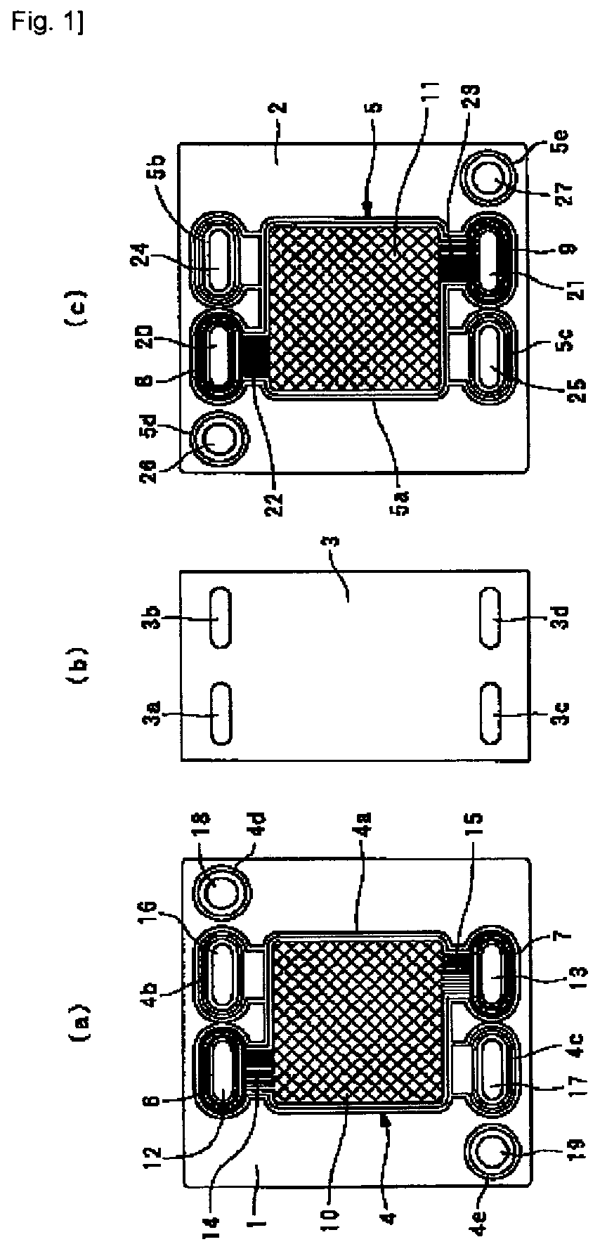
- Fig. 1 shows respective members used for a single cell of the fuel cell separators according to the embodiment.
- Fig. 2 shows one of separators for the fuel cell according to the embodiment shall be described.
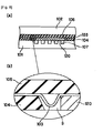
- Fig. 3 shows a gasket of the seal structure of the fuel cell separators according to the embodiment.
- Fig. 4 is a cross section view showing the sealing state of the fuel cell separators according to the embodiment.
- the seal structure for the fuel cell separators according to the present embodiment is used in case of composing a cell for a fuel cell by sandwiching an electrolyte membrane with two separators similarly to the prior art shown in Fig. 5.
- the seal structure for the fuel cell separators according to the present embodiment is composed of two separators 1, 2, an electrolyte membrane sandwiched between the separators 1, 2, and gaskets 6, 7, 8 and 9 compressing each other, via the electrolyte membrane 3, to seal rubbers 4, 5 (seal bodies) provided integrally with respective one of the separators 1, 2.
- separator 1 for communicating hydrogen gas (first fuel gas) to a fuel electrode 10 (electrode portion) while the other is the separator 2 for communicating oxygen gas (second fuel gas) to an air electrode 11 (electrode portion).
- the separator 1 is a substantially square plate member where the square electrode 10 (electrode portion) is arranged at the center and an oval inlet manifold 12 (manifold portion) for communicating hydrogen gas to the electrode 10 and an exit manifold 13 (manifold portion) are provided across the electrode 10.
- Plural passage grooves 14, 15 carved in parallel in the separator 1 for flowing hydrogen gas are formed respectively between the electrode 10 and the inlet manifold 12 and between the electrode 10 and the exit manifold 13.
- holes 16, 17 in such a manner that oxygen gas pass through by facing the inlet manifold 20 and the exit manifold 21 of the opposed other separator 2 when the separators 1, 2 are placed oppositely each other, are formed in the separator 1.
- the holes 16, 17 have the same shape as the inlet manifold 20 and the exit manifold 21.
- holes 18, 19 for cooling water are formed respectively at two corners on one diagonal of the separator 1, for passing cooling water.
- the separator 2 is a substantially square plate member equal to the separator 1, where the square electrode 11 (electrode portion) is arranged at the center and the oval inlet manifold 20 (manifold portion) for communicating oxygen gas to the electrode 11 and the exit manifold 21 (manifold portion) are provided across the electrode 11.
- Plural passage grooves 22, 23 carved in parallel in the separator 2 for communicating oxygen gas are formed respectively between the electrode 11 and the inlet manifold 20 and between the electrode 11 and the exit manifold 21.
- holes 24, 25 in such a manner that hydrogen gas pass through by facing the inlet manifold 12 and the exit manifold 13 of the opposed other separator 1 when separators 1, 2 are placed oppositely each other, are formed in the separator 2.
- the holes 24, 25 have the same shape as the inlet manifold 12 and the exit manifold 13.
- holes 26, 27 for cooling water are formed respectively at two corners on one diagonal of the separator 2, for passing cooling water.
- each separator 1, 2 is integrally provided with seal rubbers 4, 5 for sealing respective circulating gases.
- the seal rubbers 4, 5 are integrated by using injection molding, compression molding, transfer molding, screen printing, dispenser method and so on.
- the seal rubber 4 comprises a first seal portion 4a to seal an area surrounding the electrode 10, the passage grooves 14, 15, the inlet manifold 12 and the exit manifold 13, second seal portions 4b, 4c to seal independently the holes 16, 17 and third seal portions 4d, 4e to seal independently the holes 18, 19 for cooling water.
- the first seal portion 4a surrounds also the periphery of the second seal portions 4b, 4c separately, and the holes 16, 17 are surrounded doubly with the seal rubber 4.
- the seal rubber 5 comprises a first seal portion 5a to seal an area surrounding the electrode 11, the passage grooves 22, 23, the inlet manifold 20 and the exit manifold 21, second seal portions 5b, 5c to seal independently the holes 24, 25 and third seal portions 5d, 5e to seal independently the holes 26, 27 for cooling water.
- the first seal portion 5a surrounds also the periphery of the second seal portions 5b, 5c separately, and the holes 24, 25 are surrounded doubly with the seal rubber 5.
- the electrolyte membrane 3 is the one to be sandwiched between the two separators 1, 2.
- the electrolyte membrane 3 is a rectangular sheet having a size, though smaller than the whole area of the separators 1, 2, enough to include the electrodes 10, 11, the inlet manifolds 12, 20, the exit manifolds 13, 21 and the holes 16, 17, 24, 25, and through-holes 3a to 3d are opened at the position where the inlet manifolds 12, 20, the exit manifolds 13, 21 and the holes 16, 17, 24, 25 face each other.
- the electrolyte membrane 3 is not sandwiched between the separators 1, 2 at the position of holes for cooling water 18, 19, 26, 27.
- the gaskets 6, 7, 8, 9 are already attached to the separators 1, 2 in Fig. 1 or Fig. 2 and surrounds independently the periphery of respective one of the inlet manifolds 12, 20 and the exit manifolds 13, 21.
- the gaskets 6, 7, 8, 9 are placed inside the surrounding of the inlet manifolds 12, 20 and the exit manifolds 13, 21 by the first seal portions 4a, 5a of the seal rubbers 4, 5.
- the gasket 6 is shown in Fig. 3 as representative, and the gasket 6 is manufactured with a unit member as shown in Fig. 3(a) and adhered in a way to surround the inlet manifold 12, inside the surrounding of the inlet manifold 12 by the first seal portion 4a of the seal rubber 4 as shown in Fig. 3(b).
- Passage grooves 14, 15, 22, 23 communicating with the electrodes 10, 11 exist around the inlet manifolds 12, 20 and the exit manifolds 13, 21, the gaskets 6, 7, 8, 9 straddle like bridges the upper part of the plural passage grooves 14, 15, 22, 23 arranged in parallel, and concave portions carved in the separators 1, 2 of the passage grooves 14, 15, 22, 23 allows communicating respective circulation gas.
- the gaskets 6, 7, 8, 9 are the ones, as the gasket 6 shown in Fig. 3 representatively, to be formed separately from the separators 1, 2 and comprises a substrate 30 of resin film, carbon plate or the like to impart such rigidity necessary for straddling over the passage grooves 14, 15, 22, 23 and a rubber portion 31 integrated with the substrate 30.
- a substrate 30 of resin film, carbon plate or the like to impart such rigidity necessary for straddling over the passage grooves 14, 15, 22, 23 and a rubber portion 31 integrated with the substrate 30.
- adhesion by an adhesive or a selective adhesion rubber is used for the integration of the substrate 30 and the rubber portion 31, adhesion by an adhesive or a selective adhesion rubber is used.
- the resin film used for the substrate 30 of the gaskets 6, 7, 8, 9 includes PET (polyethyleneterephthalate), PEN (polyethylenenaphthalate), PI (polyimide), PPS (poly phenylene sulfide) and so on, and PI is preferable among others.
- gaskets 6, 7, 8, 9 may comprise only the substrate 30, because the substrate 30 can seal alone.
- pressure-sensitive adhesive is applied to the substrate 30 to adhere and fix it to the separators 1, 2.
- projections are provided on the separators 1, 2, holes engaging with the projections are formed in the substrate for joining the gaskets 6, 7, 8, 9 with the separators 1, 2 or other methods may be adopted.
- a single cell is then formed by sandwiching the electrolyte membrane 3 between two separators 1, 2 to which the gaskets 6, 7, 8, 9 are adhered.
- Fig. 4 is a cross section view showing essential parts sealed with the gasket 6 by sandwiching the electrolyte membrane 3 between the separators 1, 2 at the A-A portion.
- the second seal portion 5b of the seal rubber 5 surrounding the hole 24 of the separator 2 is opposed, via the electrolyte membrane 3, to the gasket 6 straddling on the passage groove 14 of the separator 1 and at the same time surrounding the inlet manifold 12 and the gasket 6 and the second seal portion 5b compress each other all around the periphery.
- the gaskets 6, 7, 8, 9 surround respectively all around the periphery of the inlet manifolds 12, 20 and the exit manifolds 13, 21, and the seal rubbers 4, 5 and the gaskets 6, 7, 8, 9 come always in a close contact with the electrolyte membrane 3 around the inlet manifolds 12, 20, the exit manifolds 13, 21 and the holes 16, 17, 24, 25 and can exhibit a better sealing, because it is unnecessary to change members opposed to the seal rubbers 4, 5 on the passage groove and the other part as in the prior art.
- the present invention can exhibit a secure sealing, without leakage of fuel gas.
Landscapes
- Life Sciences & Earth Sciences (AREA)
- Engineering & Computer Science (AREA)
- Manufacturing & Machinery (AREA)
- Sustainable Development (AREA)
- Sustainable Energy (AREA)
- Chemical & Material Sciences (AREA)
- Chemical Kinetics & Catalysis (AREA)
- Electrochemistry (AREA)
- General Chemical & Material Sciences (AREA)
- Fuel Cell (AREA)
Abstract
Description
- 1,2
- Separator
- 3
- Electrolyte membrane
- 3a, 3b, 3c, 3d
- Through-hole
- 4, 5
- Seal rubber
- 4a, 5a
- First seal portion
- 4b, 4c, 5b, 5c
- Second seal portion
- 4d, 4e, 5d, 5e
- Third seal portion
- 6, 7, 8, 9
- Gasket
- 10
- Fuel electrode
- 11
- Air electrode
- 12, 20
- Inlet manifold
- 13, 21
- Exit manifold
- 14, 15, 22, 23
- Passage groove
- 16,17,24,25
- Hole
- 18, 19, 26, 27
- Hole for cooling water
- 30
- Substrate
- 31
- Rubber portion
Claims (1)
- A seal structure for fuel cell separators comprising:two separators disposed opposite to one another, which have electrode portions, manifold portions circulating fuel gas fed to said electrode portions, and hole portions opposite to the manifold portions of the separators and facing passage grooves feeding fuel gas between said electrode portion and said manifold portion;a seal body, which is provided integrally on said separators and has a first seal portion to seal an area surrounding said electrode portion, said passage grooves and said manifold portions, and a second seal portion to seal independently said hole portion;an electrolyte membrane, sandwiched between said two separators, of a size large enough to include said electrode portion, said manifold portion and said hole portion, and of a shape with through-holes at the positions of said manifold portion and said hole portion; anda gasket surrounding said manifold portion of said separators and straddling said passage groove to enable fuel gas to communicate.
Priority Applications (1)
| Application Number | Priority Date | Filing Date | Title |
|---|---|---|---|
| US11/141,191 US7393606B2 (en) | 2003-07-02 | 2005-06-01 | Seal structure for fuel cell separator |
Applications Claiming Priority (2)
| Application Number | Priority Date | Filing Date | Title |
|---|---|---|---|
| JP2003190094A JP4403735B2 (en) | 2003-07-02 | 2003-07-02 | Fuel cell separator seal structure |
| JP2003190094 | 2003-07-02 |
Publications (3)
| Publication Number | Publication Date |
|---|---|
| EP1494305A2 true EP1494305A2 (en) | 2005-01-05 |
| EP1494305A3 EP1494305A3 (en) | 2006-10-18 |
| EP1494305B1 EP1494305B1 (en) | 2012-03-14 |
Family
ID=33432321
Family Applications (1)
| Application Number | Title | Priority Date | Filing Date |
|---|---|---|---|
| EP04014787A Expired - Lifetime EP1494305B1 (en) | 2003-07-02 | 2004-06-24 | Seal structure for fuel cell separator |
Country Status (2)
| Country | Link |
|---|---|
| EP (1) | EP1494305B1 (en) |
| JP (1) | JP4403735B2 (en) |
Cited By (1)
| Publication number | Priority date | Publication date | Assignee | Title |
|---|---|---|---|---|
| CN105932314A (en) * | 2016-05-19 | 2016-09-07 | 武汉众宇动力系统科技有限公司 | Fuel cell cathode plate sealing device, fuel cell and fuel cell stack |
Families Citing this family (2)
| Publication number | Priority date | Publication date | Assignee | Title |
|---|---|---|---|---|
| KR100766140B1 (en) | 2006-09-07 | 2007-10-10 | 현대자동차주식회사 | Gasket structure installed on separator plate of fuel cell vehicle |
| JP5321291B2 (en) | 2009-06-30 | 2013-10-23 | Nok株式会社 | Fuel cell |
Family Cites Families (7)
| Publication number | Priority date | Publication date | Assignee | Title |
|---|---|---|---|---|
| DE69229177T2 (en) * | 1992-12-31 | 1999-12-02 | Ballard Power Systems Inc., Burnaby | Membrane electrode assembly and sealing for fuel cells |
| US5527363A (en) * | 1993-12-10 | 1996-06-18 | Ballard Power Systems Inc. | Method of fabricating an embossed fluid flow field plate |
| EP1156546B1 (en) * | 1997-07-16 | 2003-10-08 | Ballard Power Systems Inc. | Method of making a resilient seal for membrane electrode assembly (MEA) in an electrochemical fuel cell |
| JP3532547B2 (en) * | 2000-11-30 | 2004-05-31 | 本田技研工業株式会社 | Method for manufacturing seal-integrated separator |
| AUPR636401A0 (en) * | 2001-07-13 | 2001-08-02 | Ceramic Fuel Cells Limited | Fuel cell stack configuration |
| WO2004049483A2 (en) * | 2002-11-28 | 2004-06-10 | Global Thermoelectric Inc. | Solid oxide fuel cell stack |
| WO2004105167A1 (en) * | 2003-05-23 | 2004-12-02 | Honda Motor Co., Ltd. | Fuel cell |
-
2003
- 2003-07-02 JP JP2003190094A patent/JP4403735B2/en not_active Expired - Fee Related
-
2004
- 2004-06-24 EP EP04014787A patent/EP1494305B1/en not_active Expired - Lifetime
Cited By (2)
| Publication number | Priority date | Publication date | Assignee | Title |
|---|---|---|---|---|
| CN105932314A (en) * | 2016-05-19 | 2016-09-07 | 武汉众宇动力系统科技有限公司 | Fuel cell cathode plate sealing device, fuel cell and fuel cell stack |
| CN105932314B (en) * | 2016-05-19 | 2018-10-26 | 武汉众宇动力系统科技有限公司 | Fuel battery negative pole plate sealing device, fuel cell and fuel cell pack |
Also Published As
| Publication number | Publication date |
|---|---|
| JP2005026058A (en) | 2005-01-27 |
| EP1494305A3 (en) | 2006-10-18 |
| JP4403735B2 (en) | 2010-01-27 |
| EP1494305B1 (en) | 2012-03-14 |
Similar Documents
| Publication | Publication Date | Title |
|---|---|---|
| US7491355B2 (en) | Method for fabricating a seal-integrated separator | |
| US7138081B2 (en) | Method for fabricating a seal-integrated separator | |
| TWI401836B (en) | Variable compressibility gaskets | |
| US6815115B2 (en) | Fuel cell and fuel cell stack | |
| US6861171B1 (en) | Gasket assembly | |
| CN103531830B (en) | With the electrolyte membrane-electrode structure of fuel cell resin frame | |
| CA2976351C (en) | Seal for solid polymer electrolyte fuel cell | |
| US9673458B2 (en) | Fuel cell | |
| US6844101B2 (en) | Separator with fluid distribution features for use with a membrane electrode assembly in a fuel cell | |
| US20030082430A1 (en) | Fuel cell gasket assembly and method of making | |
| CN101443939B (en) | Gaskets for Fuel Cells | |
| WO2007044022A3 (en) | Form-in-place fastening for fuel cell assemblies | |
| US20030127806A1 (en) | Alignment feature for a fuel cell seal | |
| JP4337394B2 (en) | Fuel cell | |
| EP1494305B1 (en) | Seal structure for fuel cell separator | |
| US7393606B2 (en) | Seal structure for fuel cell separator | |
| US20050191537A1 (en) | Fuel cell gasket having an integrated sensor | |
| US7670709B2 (en) | Fuel cell seal with integral bridge | |
| US20070009780A1 (en) | Sealing of multi-height surfaces | |
| US20040128825A1 (en) | Laminated membrane electrode seal assembly | |
| US20030013001A1 (en) | Carrier gasket for a fuel cell | |
| US20250006956A1 (en) | Film Assembly and Manufacturing Method Therefor, Fuel Cell Unit, and Fuel Cell Pack | |
| JPS63241870A (en) | Separator for fuel cells | |
| JP2004079473A (en) | Gaskets and gas separation composite plates for fuel cells |
Legal Events
| Date | Code | Title | Description |
|---|---|---|---|
| PUAI | Public reference made under article 153(3) epc to a published international application that has entered the european phase |
Free format text: ORIGINAL CODE: 0009012 |
|
| AK | Designated contracting states |
Kind code of ref document: A2 Designated state(s): AT BE BG CH CY CZ DE DK EE ES FI FR GB GR HU IE IT LI LU MC NL PL PT RO SE SI SK TR |
|
| AX | Request for extension of the european patent |
Extension state: AL HR LT LV MK |
|
| PUAL | Search report despatched |
Free format text: ORIGINAL CODE: 0009013 |
|
| AK | Designated contracting states |
Kind code of ref document: A3 Designated state(s): AT BE BG CH CY CZ DE DK EE ES FI FR GB GR HU IE IT LI LU MC NL PL PT RO SE SI SK TR |
|
| AX | Request for extension of the european patent |
Extension state: AL HR LT LV MK |
|
| 17P | Request for examination filed |
Effective date: 20070115 |
|
| AKX | Designation fees paid |
Designated state(s): DE GB IT |
|
| GRAP | Despatch of communication of intention to grant a patent |
Free format text: ORIGINAL CODE: EPIDOSNIGR1 |
|
| GRAS | Grant fee paid |
Free format text: ORIGINAL CODE: EPIDOSNIGR3 |
|
| GRAA | (expected) grant |
Free format text: ORIGINAL CODE: 0009210 |
|
| AK | Designated contracting states |
Kind code of ref document: B1 Designated state(s): DE GB IT |
|
| REG | Reference to a national code |
Ref country code: GB Ref legal event code: FG4D |
|
| REG | Reference to a national code |
Ref country code: DE Ref legal event code: R096 Ref document number: 602004036870 Country of ref document: DE Effective date: 20120510 |
|
| PLBE | No opposition filed within time limit |
Free format text: ORIGINAL CODE: 0009261 |
|
| STAA | Information on the status of an ep patent application or granted ep patent |
Free format text: STATUS: NO OPPOSITION FILED WITHIN TIME LIMIT |
|
| 26N | No opposition filed |
Effective date: 20121217 |
|
| GBPC | Gb: european patent ceased through non-payment of renewal fee |
Effective date: 20120624 |
|
| PG25 | Lapsed in a contracting state [announced via postgrant information from national office to epo] |
Ref country code: IT Free format text: LAPSE BECAUSE OF FAILURE TO SUBMIT A TRANSLATION OF THE DESCRIPTION OR TO PAY THE FEE WITHIN THE PRESCRIBED TIME-LIMIT Effective date: 20120314 |
|
| REG | Reference to a national code |
Ref country code: DE Ref legal event code: R097 Ref document number: 602004036870 Country of ref document: DE Effective date: 20121217 |
|
| PG25 | Lapsed in a contracting state [announced via postgrant information from national office to epo] |
Ref country code: GB Free format text: LAPSE BECAUSE OF NON-PAYMENT OF DUE FEES Effective date: 20120624 |
|
| PGFP | Annual fee paid to national office [announced via postgrant information from national office to epo] |
Ref country code: DE Payment date: 20230627 Year of fee payment: 20 |
|
| REG | Reference to a national code |
Ref country code: DE Ref legal event code: R071 Ref document number: 602004036870 Country of ref document: DE |