EP1494124A2 - Self powered serial-to-serial or USB-to-serial cable with loopback and isolation - Google Patents
Self powered serial-to-serial or USB-to-serial cable with loopback and isolation Download PDFInfo
- Publication number
- EP1494124A2 EP1494124A2 EP04015032A EP04015032A EP1494124A2 EP 1494124 A2 EP1494124 A2 EP 1494124A2 EP 04015032 A EP04015032 A EP 04015032A EP 04015032 A EP04015032 A EP 04015032A EP 1494124 A2 EP1494124 A2 EP 1494124A2
- Authority
- EP
- European Patent Office
- Prior art keywords
- cable
- base device
- medical device
- serial
- medical
- Prior art date
- Legal status (The legal status is an assumption and is not a legal conclusion. Google has not performed a legal analysis and makes no representation as to the accuracy of the status listed.)
- Granted
Links
Images




Classifications
-
- G—PHYSICS
- G06—COMPUTING OR CALCULATING; COUNTING
- G06F—ELECTRIC DIGITAL DATA PROCESSING
- G06F13/00—Interconnection of, or transfer of information or other signals between, memories, input/output devices or central processing units
- G06F13/38—Information transfer, e.g. on bus
- G06F13/40—Bus structure
- G06F13/4063—Device-to-bus coupling
- G06F13/4068—Electrical coupling
- G06F13/4072—Drivers or receivers
-
- A—HUMAN NECESSITIES
- A61—MEDICAL OR VETERINARY SCIENCE; HYGIENE
- A61B—DIAGNOSIS; SURGERY; IDENTIFICATION
- A61B5/00—Measuring for diagnostic purposes; Identification of persons
- A61B5/24—Detecting, measuring or recording bioelectric or biomagnetic signals of the body or parts thereof
- A61B5/30—Input circuits therefor
- A61B5/301—Input circuits therefor providing electrical separation, e.g. by using isolating transformers or optocouplers
-
- A—HUMAN NECESSITIES
- A61—MEDICAL OR VETERINARY SCIENCE; HYGIENE
- A61B—DIAGNOSIS; SURGERY; IDENTIFICATION
- A61B5/00—Measuring for diagnostic purposes; Identification of persons
- A61B5/24—Detecting, measuring or recording bioelectric or biomagnetic signals of the body or parts thereof
- A61B5/30—Input circuits therefor
- A61B5/303—Patient cord assembly, e.g. cable harness
-
- G—PHYSICS
- G05—CONTROLLING; REGULATING
- G05B—CONTROL OR REGULATING SYSTEMS IN GENERAL; FUNCTIONAL ELEMENTS OF SUCH SYSTEMS; MONITORING OR TESTING ARRANGEMENTS FOR SUCH SYSTEMS OR ELEMENTS
- G05B23/00—Testing or monitoring of control systems or parts thereof
- G05B23/02—Electric testing or monitoring
- G05B23/0205—Electric testing or monitoring by means of a monitoring system capable of detecting and responding to faults
- G05B23/0208—Electric testing or monitoring by means of a monitoring system capable of detecting and responding to faults characterized by the configuration of the monitoring system
- G05B23/0216—Human interface functionality, e.g. monitoring system providing help to the user in the selection of tests or in its configuration
-
- G—PHYSICS
- G05—CONTROLLING; REGULATING
- G05B—CONTROL OR REGULATING SYSTEMS IN GENERAL; FUNCTIONAL ELEMENTS OF SUCH SYSTEMS; MONITORING OR TESTING ARRANGEMENTS FOR SUCH SYSTEMS OR ELEMENTS
- G05B23/00—Testing or monitoring of control systems or parts thereof
- G05B23/02—Electric testing or monitoring
- G05B23/0205—Electric testing or monitoring by means of a monitoring system capable of detecting and responding to faults
- G05B23/0259—Electric testing or monitoring by means of a monitoring system capable of detecting and responding to faults characterized by the response to fault detection
- G05B23/0267—Fault communication, e.g. human machine interface [HMI]
- G05B23/0272—Presentation of monitored results, e.g. selection of status reports to be displayed; Filtering information to the user
-
- G—PHYSICS
- G06—COMPUTING OR CALCULATING; COUNTING
- G06F—ELECTRIC DIGITAL DATA PROCESSING
- G06F1/00—Details not covered by groups G06F3/00 - G06F13/00 and G06F21/00
- G06F1/26—Power supply means, e.g. regulation thereof
- G06F1/266—Arrangements to supply power to external peripherals either directly from the computer or under computer control, e.g. supply of power through the communication port, computer controlled power-strips
-
- G—PHYSICS
- G06—COMPUTING OR CALCULATING; COUNTING
- G06F—ELECTRIC DIGITAL DATA PROCESSING
- G06F11/00—Error detection; Error correction; Monitoring
- G06F11/22—Detection or location of defective computer hardware by testing during standby operation or during idle time, e.g. start-up testing
- G06F11/2205—Detection or location of defective computer hardware by testing during standby operation or during idle time, e.g. start-up testing using arrangements specific to the hardware being tested
- G06F11/221—Detection or location of defective computer hardware by testing during standby operation or during idle time, e.g. start-up testing using arrangements specific to the hardware being tested to test buses, lines or interfaces, e.g. stuck-at or open line faults
-
- G—PHYSICS
- G06—COMPUTING OR CALCULATING; COUNTING
- G06F—ELECTRIC DIGITAL DATA PROCESSING
- G06F11/00—Error detection; Error correction; Monitoring
- G06F11/30—Monitoring
- G06F11/32—Monitoring with visual or acoustical indication of the functioning of the machine
- G06F11/323—Visualisation of programs or trace data
-
- H—ELECTRICITY
- H03—ELECTRONIC CIRCUITRY
- H03K—PULSE TECHNIQUE
- H03K17/00—Electronic switching or gating, i.e. not by contact-making and –breaking
- H03K17/51—Electronic switching or gating, i.e. not by contact-making and –breaking characterised by the components used
- H03K17/78—Electronic switching or gating, i.e. not by contact-making and –breaking characterised by the components used using opto-electronic devices, i.e. light-emitting and photoelectric devices electrically- or optically-coupled
-
- H—ELECTRICITY
- H04—ELECTRIC COMMUNICATION TECHNIQUE
- H04B—TRANSMISSION
- H04B10/00—Transmission systems employing electromagnetic waves other than radio-waves, e.g. infrared, visible or ultraviolet light, or employing corpuscular radiation, e.g. quantum communication
- H04B10/80—Optical aspects relating to the use of optical transmission for specific applications, not provided for in groups H04B10/03 - H04B10/70, e.g. optical power feeding or optical transmission through water
- H04B10/801—Optical aspects relating to the use of optical transmission for specific applications, not provided for in groups H04B10/03 - H04B10/70, e.g. optical power feeding or optical transmission through water using optical interconnects, e.g. light coupled isolators, circuit board interconnections
- H04B10/802—Optical aspects relating to the use of optical transmission for specific applications, not provided for in groups H04B10/03 - H04B10/70, e.g. optical power feeding or optical transmission through water using optical interconnects, e.g. light coupled isolators, circuit board interconnections for isolation, e.g. using optocouplers
-
- H—ELECTRICITY
- H10—SEMICONDUCTOR DEVICES; ELECTRIC SOLID-STATE DEVICES NOT OTHERWISE PROVIDED FOR
- H10F—INORGANIC SEMICONDUCTOR DEVICES SENSITIVE TO INFRARED RADIATION, LIGHT, ELECTROMAGNETIC RADIATION OF SHORTER WAVELENGTH OR CORPUSCULAR RADIATION
- H10F55/00—Radiation-sensitive semiconductor devices covered by groups H10F10/00, H10F19/00 or H10F30/00 being structurally associated with electric light sources and electrically or optically coupled thereto
- H10F55/20—Radiation-sensitive semiconductor devices covered by groups H10F10/00, H10F19/00 or H10F30/00 being structurally associated with electric light sources and electrically or optically coupled thereto wherein the electric light source controls the radiation-sensitive semiconductor devices, e.g. optocouplers
-
- A—HUMAN NECESSITIES
- A61—MEDICAL OR VETERINARY SCIENCE; HYGIENE
- A61B—DIAGNOSIS; SURGERY; IDENTIFICATION
- A61B2560/00—Constructional details of operational features of apparatus; Accessories for medical measuring apparatus
- A61B2560/04—Constructional details of apparatus
- A61B2560/0443—Modular apparatus
- A61B2560/045—Modular apparatus with a separable interface unit, e.g. for communication
-
- A—HUMAN NECESSITIES
- A61—MEDICAL OR VETERINARY SCIENCE; HYGIENE
- A61B—DIAGNOSIS; SURGERY; IDENTIFICATION
- A61B2562/00—Details of sensors; Constructional details of sensor housings or probes; Accessories for sensors
- A61B2562/22—Arrangements of medical sensors with cables or leads; Connectors or couplings specifically adapted for medical sensors
- A61B2562/221—Arrangements of sensors with cables or leads, e.g. cable harnesses
- A61B2562/222—Electrical cables or leads therefor, e.g. coaxial cables or ribbon cables
-
- A—HUMAN NECESSITIES
- A61—MEDICAL OR VETERINARY SCIENCE; HYGIENE
- A61B—DIAGNOSIS; SURGERY; IDENTIFICATION
- A61B5/00—Measuring for diagnostic purposes; Identification of persons
- A61B5/145—Measuring characteristics of blood in vivo, e.g. gas concentration or pH-value ; Measuring characteristics of body fluids or tissues, e.g. interstitial fluid or cerebral tissue
- A61B5/14532—Measuring characteristics of blood in vivo, e.g. gas concentration or pH-value ; Measuring characteristics of body fluids or tissues, e.g. interstitial fluid or cerebral tissue for measuring glucose, e.g. by tissue impedance measurement
-
- H—ELECTRICITY
- H01—ELECTRIC ELEMENTS
- H01R—ELECTRICALLY-CONDUCTIVE CONNECTIONS; STRUCTURAL ASSOCIATIONS OF A PLURALITY OF MUTUALLY-INSULATED ELECTRICAL CONNECTING ELEMENTS; COUPLING DEVICES; CURRENT COLLECTORS
- H01R2201/00—Connectors or connections adapted for particular applications
- H01R2201/12—Connectors or connections adapted for particular applications for medicine and surgery
Definitions
- An aspect of the present invention relates to interface cables for medical devices which communicate with base devices.
- Examples of a base device are a standard personal computer or another device with at least one serial port or Universal Serial Bus (USB) port.
- the present invention relates to a data transfer cable for use with a glucose monitor for communications with a personal computer.
- another aspect of the present invention relates to graphical status displays for connecting a personal computer to a medical device using a data transfer cable.
- this aspect of the present invention relates to a system for generating a graphical display to assist a user in connecting a medical device to a base device.
- a medical device may be a device that monitors a medical condition and collects data, such as a blood glucose monitor.
- a medical device could also be a device that administers treatment to a patient in response to a treatment regime determined by a healthcare professional, such as a drug therapy regime for the treatment of diabetes.
- a medical device could be a combination device that both monitors a medical condition and administers a treatment in response to the medical conditions monitored.
- a serial port such as a standard serial or USB port on a base device
- the user Normally when a medical device is connected to a serial port, such as a standard serial or USB port on a base device, the user must select the type of serial port to which the device is connected. Also, when a base device has a plurality of standard serial ports, the user must configure the base device to communicate on the particular serial port to which the medical device is connected, which can cause confusion. It would be advantageous for the base device to have the ability to detect the presence of a medical device so that it may begin downloading data or performing other processes. In addition, it is not desirable to require the medical device to use a standard serial communication interface, which involves a complex connection. Such a connection may possibly require using a secondary connector on the medical device, thereby increasing costs and complexity. What is needed is an interface cable that provides isolation, automatic detection and a simple connection to the medical device.
- the automatic detection feature has great advantages in a healthcare setting where multiple vendors' software and cables are used. In such a setting, it is very annoying and tedious for the healthcare provider to figure out which port they are connected to every time they connect or re-connect a cable.
- Some serial connecting devices tie the request to send (RTS) connection and clear to send (CTS) connection together and the data terminal ready (DTR) connection and data set ready (DSR) connection together, this allows the software to determine that a cable is connected to a particular port, but does not identify to which vendor the cable belongs. Also on some computers this tie back scenario causes the power to be sent back to the PC and not to power any internal circuitry of the cable.
- RTS request to send
- DTR data terminal ready
- DSR data set ready
- the present invention provides a simple interface between medical device and base device, which provides power from the base device to the cable, thereby isolating the medical device.
- the isolation circuit prevents the user from being subject to the possible electrical hazards presented by the connection to the base device.
- the cable insures that the base device is able to identify the cable as belonging to a medical device that uses the specific software applications associated with the medical device.
- Automatic detection of the serial port address is accomplished by a loopback feature, which polls the ports of the base device to identify where the cable is located. This allows the base device to automatically identify the cable without a meter connected.
- the connectors of the cable are standard connectors familiar to most users, which make connecting the cable to a base device and to a medical device simple.
- the connectors to the base device are USB connectors as well as well known serial connectors, such as RS-232C connectors.
- graphics and text messages provide a way to pinpoint specific problems that may be preventing a successful connection of the cable to either the base device or the medical device.
- animations and messages provide a visual indicator that there is some activity between the base device, cable and the medical device.
- Fig. 1 illustrates a cable according to an embodiment of the present invention in use connecting a base device and a medical device
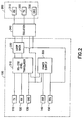
- Fig 2 shows a block diagram of a cable according to an embodiment of the present invention
- Fig. 3 shows a block diagram of a cable according to an alternate embodiment of the present invention
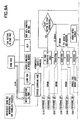
- Fig. 4A shows exemplary serial-connection circuitry of the cable shown in Fig. 2;
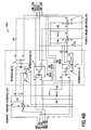
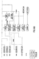
- Fig. 4B shows the isolation circuit and the connections to the medical device common to both of the cables shown in Figs. 2 and 3;
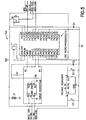
- Fig. 5 shows exemplary USB connector circuitry shown in Fig. 3;
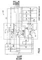
- Fig. 6 shows an alternative circuit to the circuit shown in Fig. 4B according to an alternative embodiment of the present invention.
- Fig. 7 shows a flowchart of a software loopback feature of an embodiment of the present invention as shown in Figs. 2 and 3;
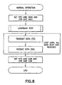
- Fig. 8 shows a flowchart of the operation of the cable according to an embodiment of the present invention.
- Fig. 9 is a flowchart showing the steps of connecting the cable to a base device and a medical device.
- Fig. 10 shows exemplary graphical and text messages that a user may receive during each of the steps in the flowchart of Fig. 9.
- Fig. 1 shows an embodiment of the invention, where the interface cable 10 for the portable medical device 30 is a self-powered serial to serial optically isolated half duplex serial transmission cable.
- Cable 10 is preferably intended for half duplex operation. However, a simple change in the electronics portion 12 enables the cable 10 for full duplex operation, which later will be in more detail.
- Cable 10 is used to connect the base device 20 which could be a personal computer or similar device with a serial port (Standard or USB) to medical device 30.
- the cable has an electronics portion 12 which may house the circuitry that enables operation of the invention.
- the cable 10 connection to the medical device 30 is a connector that connects to the data port of the medical device 30, which in the case of a blood glucose monitor would be the test strip slot.
- Fig. 2 shows a block diagram of the operation of cable 10.
- Medical device 30 preferably contains isolated side 200, while non-isolated side 100 is preferably contained within base device 20.
- Cable 10 comprises two ends or sides, an isolated side 200 of cable 10 and a non-isolated side 100. Each side 100, 200 is separated by an isolation barrier 340, which preferably comprises standard optical isolation techniques known in the art.
- the TX line 220 is used to power the electronics of cable 10. If full duplex signaling were allowed, the RX line 210 to medical device 30 would receive a similar signal or a corrupted signal from TX line 110 and would cause problems in the communications. Five of the nine standard serial cable lines are used in cable 10.
- Cable 10 uses the following lines TX line 110, RX line 120, GND line 130, DTR line 140, and RTS line 150.
- the DTR line 140 is used to power the non-isolated side 100 of the cable 10 when held high.
- DTR line 140 does not power the circuit.
- the RTS line 150 is used for multiple purposes.
- the loop back circuit 330 is signaled to execute a loop back feature which echoes back any data sent from the PC serial output to its serial input and powers down any unnecessary circuitry on the non-isolated side 100 of the isolation barrier. This is accomplished by removing power from photocoupler 155, which is in isolation circuit 340 (See Fig. 4B for more detail).
- the RTS line 150 is high, it is used to power the non-isolated side 100 of cable 10, put cable 10 in straight through mode to medical device 30, and power up the circuitry on isolated side 200 of the isolation barrier 340.
- the software application of base device 20 starts it makes RTS line 150 and DTR line 140 high in order to detect the serial cable 10 on a port automatically. After the serial cable is detected, RTS line 150 should be made low and DTR line 140 should be left high.
- the base device 20 makes RTS line 150 high. Then base device 20 transmits and receives data in a half duplex mode.
- RTS line 150 is preferably made low in order to conserve the battery power of the medical device 30 battery. If more data is requested later, the above procedure is preferably repeated. If the base device 20 is done communicating with the medical device 30, the base device 20 makes DTR line 140 low.
- Medical device 30 should be disconnected from cable 10 when not is use to increase battery life of medical device 30.
- a warning message may be presented by the software of base device 20 after the download to indicate to the user to disconnect medical device 10.
- a small delay could be added when switching the state of the RTS line 150 and DTR line 140 in order to allow them to settle into their steady states. This delay should be approximately on the order of 100ms.
- Figs. 4A and 4B are circuit diagrams of the entire cable shown in Fig. 2.
- the base device 20 makes the RTS 150 and DTR 140 lines high state, which causes a voltage regulator 144 to generate a regulated power supply voltage VDD.
- This voltage VDD is supplied to a standard RS-232 voltage level translator 142 with built in electrostatic discharge protection.
- Control lines DTR 140 or RTS 150 separately can also provide enough power to generate a regulated power supply voltage VDD from voltage regulator 144.
- Control line RTS 150 is level translated by the use of a diode to reduce its voltage level to an acceptable voltage.
- Two analog switches or multiplexers 144, 146 are used to direct the TX 110 signal back to the RX 120 signal or straight through to the TX 210 of the connected device.
- RTS 150 also turns on and off photocoupler 155 within isolation barrier 340 to enable or disable power a section of the circuitry on the isolated side of the circuit. This is used due to the fact that the TX 220 line of the connected device is supplying power to the isolated side of the circuit, so the less circuitry powered the less draw on the connected device.
- Schmidt triggered inverters 165 are used to clean or sharpen the signals received across the isolation barrier in order to be received properly by either device 100, 200.
- Fig. 3 illustrates a USB device within base device 20 according to an embodiment of the present invention.
- the previous embodiment is that in the VBUS line 190 and GND line 130 from the USB port within base device 20 are used to power the circuit on non-isolated side 100'.
- a microprocessor 510 or a logic circuit within a USB-to-serial converter 500 is used to translate the USB data stream to a serial data stream by a USB-to-serial converter 500.
- the loopback feature is implemented via software programming within the microprocessor 510 of the USB to serial converter 500. All other control lines are preferably activated the same way as in the previous embodiment.
- the isolation circuit 340 and 200 are substantially the same for either the Serial-to-Serial or the USB-to-Serial embodiment of the present invention; therefore, reference will be made to Fig. 4B.
- Figs. 5 and 4B together form the circuit diagram of the cable shown in Fig.3.
- VBUS 190 generates a regulated power supply voltage to power a microprocessor 510 used to convert USB data to serial data and vice versa.
- Microprocessor 510 software is used to direct the TX 110 signal back to the RX 120 signal or straight through to the TX 220 of the connected device.
- RTS 150 also turns on and off an optical switch 155, which when enabled provides power to the isolated side of the cable.
- base device 20 disables power to the section of the circuitry on the isolated side of the circuit that provides the communication mode signals. This is used due to the fact that the TX 210 line of the connected device is supplying power to the isolated side of the circuit, so the less circuitry powered the less draw on the connected device.
- the Schmidt triggered inverters 165 shown in figure 4B, are used to clean or sharpen the signals received across the isolation barrier in order to be received properly by either device 100', 200.
- the cable 10 may also be implemented to operate as a full duplex cable by changing the connections to the photocoupler 155 within isolation barrier 340.
- the TX 220' line from the medical device 30 is disconnected from the photocoupler 155' within isolation barrier 340'.
- the photocoupler 155' is directly powered by a dedicated power source 240.
- Power source 240 may either be internal to the medical device 30 or base device 20 or be external to both the medical 30 and base 20 devices. Power source 240 could be a battery or some other power supply.
- the RX 210' line will then be unaffected by the data being transmitted on TX 220'.
- the other circuit components, such as the optocouplers 151' and Schmidt trigger inverters 165', are the same as in Fig. 4B above.
- the present invention operates in the fashion shown in the flowchart of Fig. 8.
- the base device 20 software applications starts it makes RTS line 150 and DTR lines 140 high in order to detect the serial cable on a port automatically. After this, RTS line 150 should be made low and DTR line 140 should be left high. This allows the software application in base device 20 to echo characters back in order to make sure cable 10 is connected to base device 20, and also powers down any unnecessary circuitry on the isolated side 200 of isolation barrier 340 to reduce the drain on battery within medical device 30.
- base device 20 makes RTS line 150 high. Then base device 20 sends and receives data in a half duplex mode. Once the communication is complete, RTS line 150 should be made low in order to conserve battery power on medical device 30. If more data is requested later, the same procedure should be used. If done communicating, base device 20 makes DTR line 140 low.
- the associated software detects a variety of connection states and causes the display of appropriate graphics and text messages.
- the cable is accompanied with software that provides a graphical interface to assist the user in connecting the cable 10 to both the base device 20 and the medical device 30.
- the medical device 30 is a blood glucose meter and the base device 20 is a PC.
- An interface such as a web browser interface, presents a Home Page from which the user may select to perform a number of functions.
- the software provides step by step graphical images, including text messages, of how the meter 30 and PC 20 should be connected. If a connection is not detected, an error message as well as graphics will be prominently displayed.
- the software first detects whether the interface cable is connected to the PC (S10). While it is detecting the cable 10, the graphic shows a colored question mark between the PC end of the cable graphic and the PC graphic with the text message, "Connecting" as shown in Fig. 10, message 2. If the cable 10 is connected to the PC 20, the graphics and text shown in Fig. 10, message 1 are displayed. These graphics show the PC end of the cable graphic touching the PC graphic with the text message, "PC Port Connected to Cable”. The graphics and text shown in Fig. 10, message 3 is displayed if it is not connected. When the cable 10 is not connected to the PC, the graphic changes to show a red X between the PC end of the cable graphic and the PC 20 graphic and the text message, "Could not find connection on any port".
- the software looks for a BD blood glucose meter 30. While it is detecting the meter (S20), the graphic shows a colored question mark between the meter end of the cable graphic and the meter graphic with the text message, "Identifying" as shown in Fig. 10, message 7.
- Fig. 10, message 8 shows the graphic and text message that is displayed when the base device 20 detects the meter 30, the graphic changes to show the meter end of the cable graphic touching the meter graphic with the text message, "Identified”. If a meter is not detected, the graphic and text message of Fig. 10, message 4 is displayed, which shows a colored, preferably red, X between the meter end of the cable graphic and the meter graphic with the text message, "Could not identify meter on any port”.
- the software downloads the unique serial number from the meter and looks in the database for a match to an existing database record (S50). While it is performing this check, the graphic changes, as shown in Fig. 10, message 9, to show a graphic of small heads and a questions mark appearing over the meter with the text message, "Matching Meter to Assigned User". If no matching record is found in the database, the graphic changes to show a colored, preferably red, X in addition to the small heads with question mark graphic above the meter with the text message, "Unable to find meter user - Assign Meter User" as shown in Fig. 10, message 6. Fig. 10, message 10 shows the graphic and text that is displayed, if a matching record is found (S60), a small head graphic inside of the meter is displayed along with the text message, "Matched Assigned User to Meter.”
- the software initiates the download of information from the meter (S70, S80, S90 and S100). While the data are downloading, the graphic changes as shown in Fig. 10, message 11, which displays a series of hatched lines moving from the meter to the PC. Once the download is complete, the graphic again changes to show a preferably a flashing diskette icon on the screen of the PC graphic with the text message, "Updating the Data.” This graphics and text message changes to that shown in Fig. 10, message 12.
- the graphics and text message shown in Fig. 10, message 5 is displayed.
- the graphic and text message changes to show a colored, preferably red, X on the screen of the PC graphic and the meter color changes preferably to red with the text message, "The operation could not complete - Check the cable connection with the meter.”
- the graphical indication of both what is happening and what could be wrong if the connection is not working when making the physical connection between the blood glucose meter 30 and the PC 20 is accomplished through establishing a series of states that the software can detect.
- the graphical representations of these states are presented to the user through the display of the graphics and text messages.
- Each of the images and text messages of Fig. 10 represent a discrete state of the connection and data downloading process.
- the following are the states that are represented: Idle No activity Connecting Looking for available port connection Connected Port connection found Identifying Identifying meter Identified Meter identified Matching Matching meter with patient Matched Meter matched with patient Downloading Downloading data from meter Updating Updating database ErrorConnecting Error finding available port connection ErrorIdentifying Error identifying meter ErrorMatching Error matching meter to patient ErrorDownloading Error downloading data from meter ErrorUpdating Error updating database ErrorUnexpected Unexpected/Undefined error
- the user interface component will load the protocol component (BDMeter) and asks it to find a meter connection (S10).
- BDMeter will enumerate COM1 through COM4 looking for a cable connection (S20). If a cable connection is found, then the protocol will attempt to identify a meter (S30). Enumeration of ports will stop at the first COM port located with a BD meter attached and that meter will be used.
- the meter download component will query the database to determine which patient is associated with the given meter (S50). If a match is made then the download will proceed for that patient, uninterrupted (S60). If a match cannot be found, the user will be prompted to select a patient to be associated with the meter or to enter a new patient to be associated with the meter. If the user selects a new or existing patient download will be performed for the so-selected patient. If the user cancels selection or creation of a patient, then the entire download operation will be aborted. If a database or other system related error occurs during association, the entire download session will be aborted.
- glucose values will be downloaded (S70), verified and saved (S80) in the database.
- insulin values will be downloaded (S90) and saved (S100) in the database.
- the database update will not update values that already exist for the given meter, date and time.
- the download interface program is preferably written in a combination of C++ programming language and Assembly language.
- the Home Page is preferably written in HTML programming language.
- the charts, graphs, and forms are preferably written in C++ and Visual Basic. Of course, one of ordinary skill may use other programming languages and the invention should not be limited by the use of these programming languages.
- the meter download process is divided into three distinct layers: User Interface, Protocol and Communications.
- the purpose of this design is to facilitate handling different meters, download protocols and communications mechanisms in the future and to provide a generic data exchange format between the user interface layer and the protocol layer:
- BD.MeterControl will provide an ActiveX control implementation of the meter download user interface. It provides a single button allowing the user to initiate a download and displays images to depict the various states of the download.
- the BD.MeterControl implements the IBDObject interface and handles the following messages: BDOP_PRESHOW Moves to IDLE state BDOP_PREHIDE Prompts the user if it is alright to close the view, if a download is in progress. BDOP_PRINT Handler for print requests.
- Fig. 9 shows the processes that execute when the user initiates a download from the Meter tab.
- Each state detection step has an associated reference number that refers to the numbered images.
Landscapes
- Engineering & Computer Science (AREA)
- Physics & Mathematics (AREA)
- Health & Medical Sciences (AREA)
- Life Sciences & Earth Sciences (AREA)
- Theoretical Computer Science (AREA)
- General Engineering & Computer Science (AREA)
- General Physics & Mathematics (AREA)
- Computer Hardware Design (AREA)
- Veterinary Medicine (AREA)
- Biophysics (AREA)
- Surgery (AREA)
- Animal Behavior & Ethology (AREA)
- General Health & Medical Sciences (AREA)
- Public Health (AREA)
- Medical Informatics (AREA)
- Molecular Biology (AREA)
- Heart & Thoracic Surgery (AREA)
- Biomedical Technology (AREA)
- Pathology (AREA)
- Quality & Reliability (AREA)
- Human Computer Interaction (AREA)
- Automation & Control Theory (AREA)
- Power Engineering (AREA)
- Electromagnetism (AREA)
- Computer Networks & Wireless Communication (AREA)
- Signal Processing (AREA)
- Data Mining & Analysis (AREA)
- Measuring And Recording Apparatus For Diagnosis (AREA)
- Ultra Sonic Daignosis Equipment (AREA)
Abstract
Description
| Idle | No activity |
| Connecting | Looking for available port connection |
| Connected | Port connection found |
| Identifying | Identifying meter |
| Identified | Meter identified |
| Matching | Matching meter with patient |
| Matched | Meter matched with patient |
| Downloading | Downloading data from meter |
| Updating | Updating database |
| ErrorConnecting | Error finding available port connection |
| ErrorIdentifying | Error identifying meter |
| ErrorMatching | Error matching meter to patient |
| ErrorDownloading | Error downloading data from meter |
| ErrorUpdating | Error updating database |
| ErrorUnexpected | Unexpected/Undefined error |
The BD.MeterControl implements the IBDObject interface and handles the following messages:
| BDOP_PRESHOW | Moves to IDLE state |
| BDOP_PREHIDE | Prompts the user if it is alright to close the view, if a download is in progress. |
| BDOP_PRINT | Handler for print requests. |
Claims (21)
- A cable for connecting a medical device to a base device comprising:a serial port connector for connecting a first end of said cable to said base device;a second connector for connecting a second end of said cable to said medical device; andan optical isolation circuit isolating the medical device from the base device.
- A cable as claimed in claim 1 further comprising:a power supply in the base device that provides power to said optical isolation circuit.
- A cable as claimed in claim 2 further comprising:a loopback circuit that is used by the base device to automatically identify which of said one of said plurality of serial ports said cable is connected.
- A cable as claimed in claim 3 further comprising:wherein said loopback circuit provides signals to the base device in response to signals from the base device;said signals are interpreted by the base device, and a graphical display related to the interpreted signals is presented to the user.
- A cable as claimed in claim 4, wherein said graphical display indicates points where said cable has not made a proper connection to the base device, the medical device, or both.
- A cable as claimed in claim 1, wherein said serial port connector is a Universal Serial Bus connector.
- A cable as claimed in claim 1, wherein said serial port connector is a RS-232C connector.
- A cable for connecting a medical device to a base device to transfer data comprising:a serial port connector for connecting a first end of said cable to said base device;a second connector for connecting a second end of said cable to said medical device; andan optical isolation circuit isolating the medical device from the base device; and wherein said optical isolation circuit receives power from said base device.
- A cable as claimed in claim 8, wherein power is removed from the optical isolation circuit after a predetermined condition is satisfied.
- A cable as claimed in claim 9, wherein said predetermined condition is satisfied when all the required data has been transferred between the medical device and the base device.
- A cable as claimed in claim 9, wherein the medical device reduces the amount of power it provides to said cable.
- A cable as claimed in claim 8, wherein said serial port connector is a Universal Serial Bus connector.
- A cable as claimed in claim 8, wherein said serial port connector is a RS-232C connector.
- A cable for connecting a medical condition therapy device to a base device comprising:a serial port connector to connect to one of a plurality of serial ports in said base device;an optical isolation circuit isolating the medical condition therapy device from the base device; anda loopback circuit used to automatically identify which of said one of said plurality of serial ports said medical device is connected.
- A cable as claimed in claim 14 wherein said further comprises:returning data transmitted by the base device through a serial port in the base device to said cable to a serial port confirming said connecting device is connected to said medical device.
- A cable as claimed in claim 15, wherein said loopback circuit used to automatically identify said serial port provides a signal for a graphical display to display for the user to see or hear whether the medical device is connected or not connected to said base device or to said cable.
- A cable as claimed in claim 14, wherein power is removed from said loopback circuit allowing the medical device to transmit data relating to a medical condition to the base device.
- A cable as claimed in claim 14, wherein power is removed from the optical isolation circuit which reduces the amount of power provided to the connecting device by the medical device.
- A cable as claimed in claim 14, wherein said serial port connector is a Universal Serial Bus connector.
- A cable as claimed in claim 14, wherein said serial port connector is a RS-232C connector.
- A medical condition management kit comprising:a cable for connecting a medical device to a base device, said cable comprising an optical isolation circuit for electrically isolating a first end of the cable connected to the medical device from a second end of the cable connected to the base device while allowing signaling between the medical device and the base device; andsoftware that instructs a graphical display to display the status of connection points as a user connects the medical device to the base device via the cable.
Applications Claiming Priority (4)
| Application Number | Priority Date | Filing Date | Title |
|---|---|---|---|
| US48324703P | 2003-06-30 | 2003-06-30 | |
| US48323003P | 2003-06-30 | 2003-06-30 | |
| US483230P | 2003-06-30 | ||
| US483247P | 2003-06-30 |
Publications (3)
| Publication Number | Publication Date |
|---|---|
| EP1494124A2 true EP1494124A2 (en) | 2005-01-05 |
| EP1494124A3 EP1494124A3 (en) | 2006-09-06 |
| EP1494124B1 EP1494124B1 (en) | 2009-04-22 |
Family
ID=33436774
Family Applications (1)
| Application Number | Title | Priority Date | Filing Date |
|---|---|---|---|
| EP04015032A Expired - Lifetime EP1494124B1 (en) | 2003-06-30 | 2004-06-25 | Self powered serial-to-serial or USB-to-serial cable with loopback and isolation |
Country Status (6)
| Country | Link |
|---|---|
| US (1) | US9529762B2 (en) |
| EP (1) | EP1494124B1 (en) |
| JP (1) | JP4686141B2 (en) |
| CA (3) | CA2472403C (en) |
| DE (1) | DE602004020710D1 (en) |
| ES (1) | ES2325017T3 (en) |
Cited By (4)
| Publication number | Priority date | Publication date | Assignee | Title |
|---|---|---|---|---|
| WO2006071839A3 (en) * | 2004-12-23 | 2006-11-02 | Intel Corp | Data exchange architecture suing optical links |
| WO2007076940A1 (en) * | 2005-12-30 | 2007-07-12 | Roche Diagnostics Gmbh | Portable analytical device |
| WO2008119648A1 (en) | 2007-03-30 | 2008-10-09 | Novo Nordisk A/S | Electronic device assembly with safety electric connector |
| US9149215B2 (en) | 2005-12-30 | 2015-10-06 | Roche Diabetes Care, Inc. | Portable analytical device |
Families Citing this family (40)
| Publication number | Priority date | Publication date | Assignee | Title |
|---|---|---|---|---|
| US6850788B2 (en) | 2002-03-25 | 2005-02-01 | Masimo Corporation | Physiological measurement communications adapter |
| MXPA06013235A (en) | 2004-05-14 | 2007-02-28 | Bayer Healthcare Llc | Method and apparatus for implementing patient data download for multiple different meter types. |
| JP4275583B2 (en) * | 2004-06-24 | 2009-06-10 | ユーディナデバイス株式会社 | Electronic module |
| JP2007050115A (en) * | 2005-08-18 | 2007-03-01 | Pentax Corp | Endoscope system |
| JP2007282856A (en) * | 2006-04-17 | 2007-11-01 | Matsushita Electric Works Ltd | Sphygmomanometry device and blood pressure measuring system using the same |
| US8840549B2 (en) | 2006-09-22 | 2014-09-23 | Masimo Corporation | Modular patient monitor |
| ES2712778T3 (en) | 2007-05-30 | 2019-05-14 | Ascensia Diabetes Care Holdings Ag | Method and system to manage health data |
| JP5265207B2 (en) * | 2008-01-29 | 2013-08-14 | オリンパスメディカルシステムズ株式会社 | Adapter device and medical device system |
| US8030891B2 (en) | 2008-04-10 | 2011-10-04 | Smiths Medical Asd, Inc. | Ambulatory medical device with electrical isolation from connected peripheral device |
| JP5209436B2 (en) * | 2008-10-23 | 2013-06-12 | シスメックス株式会社 | Sample analyzer, sample analysis method, and computer program |
| US8135876B2 (en) * | 2008-12-31 | 2012-03-13 | Fresenius Medical Care Holdings, Inc. | Identifying when a USB self-powered device is connected to a medical device by triggering an alert about a potential risk to patient |
| US8145800B2 (en) | 2008-12-31 | 2012-03-27 | Fresenius Medical Card Holdings, Inc. | Identifying when a USB self-powered device is connected to a medical device by triggering an alert about a potential risk to patient |
| US20100217803A1 (en) * | 2009-01-29 | 2010-08-26 | Ivy Biomedical Systems, Inc. | Interface device for communication between a medical device and a computer |
| US20100268053A1 (en) * | 2009-04-15 | 2010-10-21 | Abbott Diabetes Care Inc. | Method and Device for Detecting USB Cable Connection |
| US20110208015A1 (en) | 2009-07-20 | 2011-08-25 | Masimo Corporation | Wireless patient monitoring system |
| US20120142084A1 (en) * | 2009-08-11 | 2012-06-07 | Bayer Healthcare Llc | Graphical interface for analyte meter |
| US9153112B1 (en) | 2009-12-21 | 2015-10-06 | Masimo Corporation | Modular patient monitor |
| US20120069846A1 (en) * | 2010-09-17 | 2012-03-22 | Battelle Memorial Institute | Serial Communication Tapping and Transmission to Routable Networks |
| JP5177460B2 (en) * | 2010-12-10 | 2013-04-03 | ブラザー工業株式会社 | Information processing system |
| US8504853B2 (en) | 2011-05-18 | 2013-08-06 | Nokia Corporation | Method, apparatus, and computer program product for cable detection and power negotiation |
| EP2766834B1 (en) * | 2011-10-13 | 2022-04-20 | Masimo Corporation | Medical monitoring hub |
| US9943269B2 (en) | 2011-10-13 | 2018-04-17 | Masimo Corporation | System for displaying medical monitoring data |
| US10149616B2 (en) | 2012-02-09 | 2018-12-11 | Masimo Corporation | Wireless patient monitoring device |
| US9749232B2 (en) | 2012-09-20 | 2017-08-29 | Masimo Corporation | Intelligent medical network edge router |
| US9946682B2 (en) | 2013-01-28 | 2018-04-17 | Hewlett-Packard Development Company, L.P. | Detecting device installation and removal on a port |
| US9411369B2 (en) * | 2013-09-19 | 2016-08-09 | Apple Inc. | Power distribution in a docking station |
| US10832818B2 (en) | 2013-10-11 | 2020-11-10 | Masimo Corporation | Alarm notification system |
| US9606953B2 (en) | 2014-03-13 | 2017-03-28 | Nokia Technologies Oy | Method, apparatus, and computer program product for entering accessory docking mode in USB type C |
| US9847928B2 (en) * | 2014-09-30 | 2017-12-19 | Alcatel-Lucent Usa Inc. | Verifying connector placement via loopback schemas |
| US10503677B2 (en) | 2015-11-16 | 2019-12-10 | Hewlett-Packard Development Company, L.P. | Data communication cables with power |
| US10617302B2 (en) | 2016-07-07 | 2020-04-14 | Masimo Corporation | Wearable pulse oximeter and respiration monitor |
| WO2019075510A1 (en) * | 2017-10-18 | 2019-04-25 | ResMed Pty Ltd | Respiratory apparatus with multiple power supplies |
| US10693717B2 (en) * | 2018-02-03 | 2020-06-23 | Adva Optical Networking Se | Assisted port identification by connection an Activation device to a physical port and detecting a state change for a particular software virtual interface |
| EP3782165A1 (en) | 2018-04-19 | 2021-02-24 | Masimo Corporation | Mobile patient alarm display |
| US12495968B2 (en) | 2018-10-12 | 2025-12-16 | Masimo Corporation | System for transmission of sensor data using dual communication protocol |
| USD1013179S1 (en) | 2018-10-12 | 2024-01-30 | Masimo Corporation | Sensor device |
| USD957648S1 (en) | 2018-10-12 | 2022-07-12 | Masimo Corporation | Dongle |
| JP7422751B2 (en) | 2018-10-12 | 2024-01-26 | マシモ・コーポレイション | patient monitor system |
| US11336469B2 (en) * | 2019-12-13 | 2022-05-17 | Dell Products L.P. | Cable isolation system |
| EP4432919A1 (en) | 2022-01-05 | 2024-09-25 | Masimo Corporation | Wrist and finger worn pulse oximetry system |
Family Cites Families (34)
| Publication number | Priority date | Publication date | Assignee | Title |
|---|---|---|---|---|
| US3742947A (en) | 1971-08-26 | 1973-07-03 | American Optical Corp | Optically isolated electro-medical device |
| US4498716A (en) * | 1982-04-01 | 1985-02-12 | Ward Marvin W | Data monitoring connector for testing transmission links |
| US5481741A (en) * | 1986-04-14 | 1996-01-02 | National Instruments Corporation | Method and apparatus for providing attribute nodes in a graphical data flow environment |
| US4908819A (en) * | 1987-06-08 | 1990-03-13 | Seiscor Technologies, Inc. | Integrated data voice multiplexer supporting handshake and loop-back protocols |
| US4976681A (en) | 1988-04-27 | 1990-12-11 | Aries Medical, Inc. | Pacer interface device |
| GB8913952D0 (en) * | 1989-06-16 | 1989-08-02 | Texas Instruments Ltd | Line interface circuit and method of testing such a circuit |
| DE4113920A1 (en) | 1991-04-29 | 1992-11-05 | Ulrich Karstein Datentechnik | Data exchange set=up between personal computer and programmable memory - uses multipole connectors with interface circuitry and control circuits for serial transmissions |
| EP0632913B1 (en) * | 1992-03-25 | 2001-10-31 | Sun Microsystems, Inc. | Fiber optic memory coupling system |
| US5566339A (en) * | 1992-10-23 | 1996-10-15 | Fox Network Systems, Inc. | System and method for monitoring computer environment and operation |
| US5691898A (en) * | 1995-09-27 | 1997-11-25 | Immersion Human Interface Corp. | Safe and low cost computer peripherals with force feedback for consumer applications |
| US5809226A (en) * | 1996-04-12 | 1998-09-15 | Xerox Corporation | Method and apparatus for testing a connection between digital processing modules, such as in digital printing |
| US5793366A (en) * | 1996-11-12 | 1998-08-11 | Sony Corporation | Graphical display of an animated data stream between devices on a bus |
| JPH1027038A (en) | 1996-07-09 | 1998-01-27 | Toyoda Mach Works Ltd | Connection cable |
| JPH10307646A (en) | 1997-05-08 | 1998-11-17 | Seiko Denshi Kiki Kk | Connection cable for information equipment and coordinate reading system |
| US5938754A (en) * | 1997-11-26 | 1999-08-17 | National Instruments Corporation | Fieldbus connector including dual connectors |
| JP3437806B2 (en) | 1998-10-26 | 2003-08-18 | 株式会社ソニー・コンピュータエンタテインメント | Portable electronic device, power adapter device, and recording medium |
| US6730025B1 (en) * | 1998-11-03 | 2004-05-04 | Harry Louis Platt | Hand held physiological signal acquisition device |
| JP2000148303A (en) | 1998-11-18 | 2000-05-26 | Nec Yonezawa Ltd | Electronic devices to which external devices can be connected |
| GB2349283A (en) | 1999-04-17 | 2000-10-25 | Data Acquisition Systems Ltd | Isolated power supply for a peripheral device coupled to a computer |
| US6602191B2 (en) * | 1999-12-17 | 2003-08-05 | Q-Tec Systems Llp | Method and apparatus for health and disease management combining patient data monitoring with wireless internet connectivity |
| US6651177B1 (en) * | 2000-02-10 | 2003-11-18 | Ncr Corporation | Circuit and method of providing power to an external peripheral |
| US6751253B1 (en) * | 2000-04-05 | 2004-06-15 | Harris Corporation | Communication port-powered digital communication interface for upgrading software-reconfigurable test set |
| US6580948B2 (en) * | 2000-04-25 | 2003-06-17 | Medtronic, Inc. | Interface devices for instruments in communication with implantable medical devices |
| US6686838B1 (en) * | 2000-09-06 | 2004-02-03 | Xanboo Inc. | Systems and methods for the automatic registration of devices |
| US6975968B2 (en) * | 2001-02-08 | 2005-12-13 | Olympus Corporation | Medical system control apparatus, and method for dealing with trouble with the medical system control apparatus |
| US6907283B2 (en) * | 2001-03-02 | 2005-06-14 | Ge Medical Systems Information Technologies, Inc. | Patient telemetry device with auto-compensation for impedance changes in leadset antenna |
| JP4803893B2 (en) * | 2001-03-30 | 2011-10-26 | 富士通テン株式会社 | Measurement control device |
| EP1397068A2 (en) * | 2001-04-02 | 2004-03-17 | Therasense, Inc. | Blood glucose tracking apparatus and methods |
| JP2002318614A (en) | 2001-04-23 | 2002-10-31 | Thk Co Ltd | Servo system diagnostic controller using portable terminal |
| JP2003046509A (en) | 2001-07-31 | 2003-02-14 | Canon Inc | Information processing apparatus, information processing system, bus configuration management method, storage medium, and program |
| US7299088B1 (en) * | 2002-06-02 | 2007-11-20 | Nitish V Thakor | Apparatus and methods for brain rhythm analysis |
| EP1369788A3 (en) * | 2002-06-04 | 2007-07-04 | Bayer HealthCare LLC | RS232C interface system |
| US20040034496A1 (en) * | 2002-08-13 | 2004-02-19 | Correll Jeffrey N. | Displaying functionality of a hardware device in a measurement system |
| US6885978B2 (en) * | 2003-03-19 | 2005-04-26 | Cisco Technology, Inc. | Auto-determination of DTE/DCE connection |
-
2004
- 2004-06-22 US US10/872,779 patent/US9529762B2/en active Active
- 2004-06-23 CA CA2472403A patent/CA2472403C/en not_active Expired - Lifetime
- 2004-06-23 CA CA3013814A patent/CA3013814A1/en active Pending
- 2004-06-23 CA CA2820518A patent/CA2820518C/en not_active Expired - Lifetime
- 2004-06-24 JP JP2004187034A patent/JP4686141B2/en not_active Expired - Fee Related
- 2004-06-25 ES ES04015032T patent/ES2325017T3/en not_active Expired - Lifetime
- 2004-06-25 DE DE602004020710T patent/DE602004020710D1/en not_active Expired - Lifetime
- 2004-06-25 EP EP04015032A patent/EP1494124B1/en not_active Expired - Lifetime
Cited By (10)
| Publication number | Priority date | Publication date | Assignee | Title |
|---|---|---|---|---|
| WO2006071839A3 (en) * | 2004-12-23 | 2006-11-02 | Intel Corp | Data exchange architecture suing optical links |
| US7272277B2 (en) | 2004-12-23 | 2007-09-18 | Intel Corporation | Data exchange architecture using optical links |
| WO2007076940A1 (en) * | 2005-12-30 | 2007-07-12 | Roche Diagnostics Gmbh | Portable analytical device |
| EP2335568A3 (en) * | 2005-12-30 | 2011-10-05 | Roche Diagnostics GmbH | Portable analytical device, in particular blood glucose measuring device |
| US9149215B2 (en) | 2005-12-30 | 2015-10-06 | Roche Diabetes Care, Inc. | Portable analytical device |
| US9816956B2 (en) | 2005-12-30 | 2017-11-14 | Roche Diabetes Care, Inc. | Portable analytical device |
| US10732140B2 (en) | 2005-12-30 | 2020-08-04 | Roche Diabetes Care, Inc. | Portable analytical device |
| WO2008119648A1 (en) | 2007-03-30 | 2008-10-09 | Novo Nordisk A/S | Electronic device assembly with safety electric connector |
| CN101652094B (en) * | 2007-03-30 | 2011-09-07 | 诺沃-诺迪斯克有限公司 | Electronic device assembly with safety electric connector |
| US8435394B2 (en) | 2007-03-30 | 2013-05-07 | Novo Nordisk A/S | Electronic device assembly with safety electric connector |
Also Published As
| Publication number | Publication date |
|---|---|
| DE602004020710D1 (en) | 2009-06-04 |
| JP2005038417A (en) | 2005-02-10 |
| CA2820518A1 (en) | 2004-12-30 |
| EP1494124B1 (en) | 2009-04-22 |
| CA2472403C (en) | 2013-09-03 |
| CA3013814A1 (en) | 2004-12-30 |
| ES2325017T3 (en) | 2009-08-24 |
| CA2820518C (en) | 2018-09-04 |
| US20050001179A1 (en) | 2005-01-06 |
| CA2472403A1 (en) | 2004-12-30 |
| EP1494124A3 (en) | 2006-09-06 |
| JP4686141B2 (en) | 2011-05-18 |
| US9529762B2 (en) | 2016-12-27 |
Similar Documents
| Publication | Publication Date | Title |
|---|---|---|
| US9529762B2 (en) | Self powered serial-to-serial or USB-to-serial cable with loopback and isolation | |
| EP2235906B1 (en) | Method and system for wireless medical device communication | |
| EP2218026B1 (en) | Method and system for multi-device communication | |
| EP0699046B1 (en) | Patient monitor and support system | |
| US8652037B2 (en) | Data collection system and interface | |
| US20100198032A1 (en) | Portable handheld medical diagnostic device having a mezzanine circuit board with a universal connection interface | |
| US20090005651A1 (en) | Portable systems, devices and methods for displaying varied information depending on usage circumstances | |
| EP1455272A2 (en) | Wireless human interface device host interface supporting both BIOS and OS interface operations | |
| KR20200005744A (en) | System for pairing medical system to network controller using dongle | |
| EP1743268A4 (en) | Medical patient monitoring and data input systems, methods and user interfaces | |
| CN102663244A (en) | Communication adapter for ambulant medical or therapeutic devices | |
| WO1994024929A9 (en) | Patient monitor and support system | |
| EP3058358B1 (en) | Communication interface clip for a handheld medical device | |
| JPH08506192A (en) | Modular microprocessor-based health monitoring system | |
| EP1982426B1 (en) | A system for managing memory storing data in one or more wireless transceiver devices | |
| US20210315529A1 (en) | Monitoring device | |
| AU2022231711A1 (en) | Apparatus for controlling operation of continuous blood glucose tester | |
| WO2018030769A1 (en) | Portable complex sensor device for measuring multiple items of biometric information, and measurement method | |
| JP2025033411A (en) | Information processing system, information processing method, and program | |
| Luan | Modularized PCA pump design for an ICE-informed medical device coordination framework | |
| CN113113121A (en) | Medical information management system and method and mobile terminal | |
| CN112788983A (en) | Monitoring method for mobile monitoring equipment and mobile monitoring equipment | |
| CN107643969A (en) | The control method of key response, client and monitoring device in a kind of monitoring device | |
| JP2002112971A (en) | Health information terminal |
Legal Events
| Date | Code | Title | Description |
|---|---|---|---|
| PUAI | Public reference made under article 153(3) epc to a published international application that has entered the european phase |
Free format text: ORIGINAL CODE: 0009012 |
|
| AK | Designated contracting states |
Kind code of ref document: A2 Designated state(s): AT BE BG CH CY CZ DE DK EE ES FI FR GB GR HU IE IT LI LU MC NL PL PT RO SE SI SK TR |
|
| AX | Request for extension of the european patent |
Extension state: AL HR LT LV MK |
|
| PUAL | Search report despatched |
Free format text: ORIGINAL CODE: 0009013 |
|
| AK | Designated contracting states |
Kind code of ref document: A3 Designated state(s): AT BE BG CH CY CZ DE DK EE ES FI FR GB GR HU IE IT LI LU MC NL PL PT RO SE SI SK TR |
|
| AX | Request for extension of the european patent |
Extension state: AL HR LT LV MK |
|
| 17P | Request for examination filed |
Effective date: 20070227 |
|
| AKX | Designation fees paid |
Designated state(s): DE ES FR GB IT |
|
| 17Q | First examination report despatched |
Effective date: 20070730 |
|
| GRAP | Despatch of communication of intention to grant a patent |
Free format text: ORIGINAL CODE: EPIDOSNIGR1 |
|
| GRAS | Grant fee paid |
Free format text: ORIGINAL CODE: EPIDOSNIGR3 |
|
| GRAA | (expected) grant |
Free format text: ORIGINAL CODE: 0009210 |
|
| AK | Designated contracting states |
Kind code of ref document: B1 Designated state(s): DE ES FR GB IT |
|
| REG | Reference to a national code |
Ref country code: GB Ref legal event code: FG4D |
|
| REF | Corresponds to: |
Ref document number: 602004020710 Country of ref document: DE Date of ref document: 20090604 Kind code of ref document: P |
|
| REG | Reference to a national code |
Ref country code: ES Ref legal event code: FG2A Ref document number: 2325017 Country of ref document: ES Kind code of ref document: T3 |
|
| PLBE | No opposition filed within time limit |
Free format text: ORIGINAL CODE: 0009261 |
|
| STAA | Information on the status of an ep patent application or granted ep patent |
Free format text: STATUS: NO OPPOSITION FILED WITHIN TIME LIMIT |
|
| 26N | No opposition filed |
Effective date: 20100125 |
|
| REG | Reference to a national code |
Ref country code: FR Ref legal event code: PLFP Year of fee payment: 13 |
|
| REG | Reference to a national code |
Ref country code: FR Ref legal event code: PLFP Year of fee payment: 14 |
|
| REG | Reference to a national code |
Ref country code: FR Ref legal event code: PLFP Year of fee payment: 15 |
|
| PGFP | Annual fee paid to national office [announced via postgrant information from national office to epo] |
Ref country code: IT Payment date: 20221130 Year of fee payment: 19 Ref country code: GB Payment date: 20221117 Year of fee payment: 19 Ref country code: FR Payment date: 20221116 Year of fee payment: 19 Ref country code: ES Payment date: 20221118 Year of fee payment: 19 Ref country code: DE Payment date: 20221125 Year of fee payment: 19 |
|
| REG | Reference to a national code |
Ref country code: DE Ref legal event code: R119 Ref document number: 602004020710 Country of ref document: DE |
|
| GBPC | Gb: european patent ceased through non-payment of renewal fee |
Effective date: 20230625 |
|
| PG25 | Lapsed in a contracting state [announced via postgrant information from national office to epo] |
Ref country code: DE Free format text: LAPSE BECAUSE OF NON-PAYMENT OF DUE FEES Effective date: 20240103 Ref country code: GB Free format text: LAPSE BECAUSE OF NON-PAYMENT OF DUE FEES Effective date: 20230625 |
|
| PG25 | Lapsed in a contracting state [announced via postgrant information from national office to epo] |
Ref country code: FR Free format text: LAPSE BECAUSE OF NON-PAYMENT OF DUE FEES Effective date: 20230630 |
|
| PG25 | Lapsed in a contracting state [announced via postgrant information from national office to epo] |
Ref country code: IT Free format text: LAPSE BECAUSE OF NON-PAYMENT OF DUE FEES Effective date: 20230625 |
|
| REG | Reference to a national code |
Ref country code: ES Ref legal event code: FD2A Effective date: 20240801 |
|
| PG25 | Lapsed in a contracting state [announced via postgrant information from national office to epo] |
Ref country code: ES Free format text: LAPSE BECAUSE OF NON-PAYMENT OF DUE FEES Effective date: 20230626 |
|
| PG25 | Lapsed in a contracting state [announced via postgrant information from national office to epo] |
Ref country code: ES Free format text: LAPSE BECAUSE OF NON-PAYMENT OF DUE FEES Effective date: 20230626 |