EP1494088A2 - Cleaning roller with specific brush filaments, used in an image forming apparatus and process unit for cleaning a contact charger, related methods of removing deposit - Google Patents
Cleaning roller with specific brush filaments, used in an image forming apparatus and process unit for cleaning a contact charger, related methods of removing deposit Download PDFInfo
- Publication number
- EP1494088A2 EP1494088A2 EP04013484A EP04013484A EP1494088A2 EP 1494088 A2 EP1494088 A2 EP 1494088A2 EP 04013484 A EP04013484 A EP 04013484A EP 04013484 A EP04013484 A EP 04013484A EP 1494088 A2 EP1494088 A2 EP 1494088A2
- Authority
- EP
- European Patent Office
- Prior art keywords
- brush
- filaments
- rotary shaft
- shaft element
- roller
- Prior art date
- Legal status (The legal status is an assumption and is not a legal conclusion. Google has not performed a legal analysis and makes no representation as to the accuracy of the status listed.)
- Granted
Links
Images




Classifications
-
- G—PHYSICS
- G03—PHOTOGRAPHY; CINEMATOGRAPHY; ANALOGOUS TECHNIQUES USING WAVES OTHER THAN OPTICAL WAVES; ELECTROGRAPHY; HOLOGRAPHY
- G03G—ELECTROGRAPHY; ELECTROPHOTOGRAPHY; MAGNETOGRAPHY
- G03G21/00—Arrangements not provided for by groups G03G13/00 - G03G19/00, e.g. cleaning, elimination of residual charge
- G03G21/0005—Arrangements not provided for by groups G03G13/00 - G03G19/00, e.g. cleaning, elimination of residual charge for removing solid developer or debris from the electrographic recording medium
- G03G21/0035—Arrangements not provided for by groups G03G13/00 - G03G19/00, e.g. cleaning, elimination of residual charge for removing solid developer or debris from the electrographic recording medium using a brush; Details of cleaning brushes, e.g. fibre density
-
- G—PHYSICS
- G03—PHOTOGRAPHY; CINEMATOGRAPHY; ANALOGOUS TECHNIQUES USING WAVES OTHER THAN OPTICAL WAVES; ELECTROGRAPHY; HOLOGRAPHY
- G03G—ELECTROGRAPHY; ELECTROPHOTOGRAPHY; MAGNETOGRAPHY
- G03G15/00—Apparatus for electrographic processes using a charge pattern
- G03G15/02—Apparatus for electrographic processes using a charge pattern for laying down a uniform charge, e.g. for sensitising; Corona discharge devices
- G03G15/0258—Apparatus for electrographic processes using a charge pattern for laying down a uniform charge, e.g. for sensitising; Corona discharge devices provided with means for the maintenance of the charging apparatus, e.g. cleaning devices, ozone removing devices G03G15/0225, G03G15/0291 takes precedence
-
- G—PHYSICS
- G03—PHOTOGRAPHY; CINEMATOGRAPHY; ANALOGOUS TECHNIQUES USING WAVES OTHER THAN OPTICAL WAVES; ELECTROGRAPHY; HOLOGRAPHY
- G03G—ELECTROGRAPHY; ELECTROPHOTOGRAPHY; MAGNETOGRAPHY
- G03G2221/00—Processes not provided for by group G03G2215/00, e.g. cleaning or residual charge elimination
- G03G2221/0005—Cleaning of residual toner
-
- G—PHYSICS
- G03—PHOTOGRAPHY; CINEMATOGRAPHY; ANALOGOUS TECHNIQUES USING WAVES OTHER THAN OPTICAL WAVES; ELECTROGRAPHY; HOLOGRAPHY
- G03G—ELECTROGRAPHY; ELECTROPHOTOGRAPHY; MAGNETOGRAPHY
- G03G2221/00—Processes not provided for by group G03G2215/00, e.g. cleaning or residual charge elimination
- G03G2221/0026—Cleaning of foreign matter, e.g. paper powder, from imaging member
- G03G2221/0068—Cleaning mechanism
- G03G2221/0089—Mechanical
Definitions
- the present invention relates to a cleaning device that removes toner attached onto a surface of a member to be cleaned, such as a charging member that charges a surface of an image carrier while contacting the surface of the image carrier, and relates to an image forming apparatus and a process unit including the cleaning device.
- the present invention further relates to a method of removing deposit from a surface of a member to be cleaned, and relates to a method of forming an image.
- an image forming apparatus such as a copying machine, a printer, a facsimile machine, or other similar image forming apparatuses, includes a cleaning device that cleans a member stained by toner, for example, by use of a brush roller.
- a cleaning device that cleans a member stained by toner, for example, by use of a brush roller.
- Examples of such a member to be cleaned include an image carrier, such as a photoreceptor, and a charging member, such as a charging roller configured to charge the photoreceptor while contacting the surface of the photoreceptor.
- This type of the conventional cleaning device using a brush roller often needs a drive device for driving the brush roller. Further, the cleaning device needs a device for regulating an amount of intrusion of a brush of the brush roller into a desired member to be cleaned to control permanent deformation of the brush, that is, so-called yield of the brush.
- the drive device and the device for regulating the intrusion amount of the brush increase the cost of the cleaning device and make the configuration of the cleaning device complicated.
- the present inventor determined it is desirable to provide a cleaning device, an image forming apparatus and a process unit including the cleaning device that have a low-cost and simple configuration without a drive device for driving a brush roller of the cleaning device and a device for regulating an intrusion amount of a brush of the brush roller and that control the permanent deformation of the brush while enhancing cleaning performance of the brush roller.
- the present inventor determined it is desirable to provide a method of removing deposit from a surface of a member to be cleaned and a method of forming an image that control permanent deformation of a brush of a brush roller while enhancing cleaning performance of the brush roller.
- a cleaning device includes a brush roller configured to remove deposit from a surface of a member to be cleaned while rotating by following a movement of the surface of the member to be cleaned.
- the brush roller includes a rotary shaft element and a brush provided on the rotary shaft element. The brush abuts the surface of the member to be cleaned due to a weight of the brush roller.
- the brush includes filaments, and the brush roller satisfies a following inequation, Y / X ⁇ 2.8, where Y is a diameter (denier) of each of the filaments, and X is a length (mm) of each of the filaments.
- an image forming apparatus includes an image carrier configured to carry an image on a surface of the image carrier, a charging member configured to charge the surface of the image carrier while contacting the surface of the image carrier, a toner image forming device configured to form a toner image on the surface of the image carrier by use of toner, and a cleaning device configured to remove toner attached onto a surface of the charging member.
- the cleaning device includes a brush roller configured to rotate by following a movement of the surface of the charging member.
- the brush roller includes a rotary shaft element and a brush provided on the rotary shaft element. The brush abuts the surface of the charging member due to a weight of the brush roller.
- the brush includes filaments, and the brush roller satisfies a following inequation, Y / X ⁇ 2.8, where Y is a diameter (denier) of each of the filaments, and X is a length (mm) of each of the filaments.
- a process unit for use in an image forming apparatus including a latent image carrier configured to carry a latent image on a surface of the latent image carrier, and a developing device configured to develop the latent image on the latent image carrier with toner, includes at least the latent image carrier, a member to be cleaned that contact the surface of the latent image carrier, and the above-described cleaning device configured to remove toner attached onto the surface of the member to be cleaned.
- a method of removing deposit from a surface of a member to be cleaned includes steps of, abutting a brush, which is provided on a rotary shaft element of a brush roller, against the surface of the member to be cleaned due to a weight of the brush roller; and rotating the brush roller by following a movement of the surface of the member to be cleaned.
- the brush includes filaments, and the brush roller satisfies a following inequation, Y / X ⁇ 2.8, where Y is a diameter (denier) of each of the filaments, and X is a length (mm) of each of the filaments.
- a method of forming an image includes steps of charging a surface of an image carrier by contacting a charging member with the surface of the image carrier; forming a toner image on the surface of the image carrier; and removing toner attached onto a surface of the charging member by abutting a brush, which is provided on a rotary shaft element of a brush roller, against the surface of the charging member due to a weight of the brush roller and by rotating the brush roller by following a movement of the surface of the charging member.
- the brush includes filaments, and the brush roller satisfies a following inequation, Y / X ⁇ 2.8, where Y is a diameter (denier) of each of the filaments, and X is a length (mm) of each of the filaments.
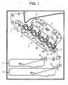
- FIG. 1 is a schematic view of a color laser printer according to an embodiment of the present invention.
- the laser printer of FIG. 1 includes toner image forming units 1Y, 1M, 1C, and 1K that form yellow, magenta, cyan, and black toner images, respectively.
- the reference letters “Y”, “M”, “C”, and “K” indicate members used for forming a yellow toner image, a magenta toner image, a cyan toner image, and a black toner image, respectively.
- the toner image forming units 1Y, 1M, 1C, and 1K include image carriers or latent image carriers, such as drum-shaped photoreceptors 11Y, 11M, 11C, and 11K.
- the laser printer further includes a laser writing unit 2, sheet feeding cassettes 3 and 4, a pair of registration rollers 5, a transfer unit 6, a belt-fixing type fixing unit 7, and a sheet discharging tray 8.
- the laser printer further includes a manual sheet feeding tray, toner cartridges, waste toner collecting bottles, a duplex/reverse unit, and a power supply unit, all of which are not shown.
- the laser writing unit 2 includes a laser light source (not shown), a polygon mirror 2a, f-theta lenses 2b, reflection mirrors, etc., and emits laser beams toward surfaces of the photoreceptors 11Y, 11M, 11C, and 11K, respectively, in accordance with image data.
- the toner image forming units 1Y, 1M, 1C, and 1K form yellow, magenta, cyan, and black toner images, respectively, and their configurations are substantially the same except for the color of their toner. For this reason, only the configuration and operation of the toner image forming unit 1Y will be described hereinafter.
- FIG. 2 is an enlarged view of the toner image forming unit 1Y that forms a yellow toner image.
- the toner image forming unit 1Y includes a process unit 10Y and a developing device 20Y.
- the process unit 10Y includes a brush roller 12Y, a counter blade 13Y, and a discharging lamp 14Y, in addition to the photoreceptor 11Y.
- the brush roller 12Y applies a lubricant onto the surface of the photoreceptor 11Y.
- the counter blade 13Y is swingable to clean the surface of the photoreceptor 11Y.
- the discharging lamp 14Y discharges the surface of the photoreceptor 11Y.
- the process unit 10Y further includes a charging roller 15Y that uniformly charges the surface of the photoreceptor 11Y, and a roller cleaning device 16Y that cleans the surface of the charging roller 15Y.
- the process unit 10Y may be configured to be detachably attached to the main body of the laser printer of FIG. 1. Elements integrally accommodated in the process unit 10Y are not limited to the above-described elements, and may be changed.
- the charging roller 15Y is brought into contact with the photoreceptor 11Y, and is applied with an alternating current bias voltage by a power supply (not shown).
- the charging roller 15Y uniformly charges the surface of the photoreceptor 11Y while being driven to rotate by a drive device (not shown) such that the moving direction of the surface of the charging roller 15Y is opposite to the moving direction of the surface of the photoreceptor 11Y at a contact part between the charging roller 15Y and the photoreceptor 11Y.
- the laser writing unit 2 irradiates the surface of the photoreceptor 11Y with an optically modulated and deflected laser beam (L), thereby forming an electrostatic latent image on the surface of the photoreceptor 11Y. Even if the counter blade 13Y cleans the surface of the photoreceptor 11Y, a small amount of toner, which has not been removed from the surface of the photoreceptor 11Y by the counter blade 13Y, remains on the surface of the photoreceptor 11Y.
- Such residual toner remaining on the surface of the photoreceptor 11Y attaches onto the charging roller 15Y which rotates while contacting the surface of the photoreceptor 11Y, as a stain. If the stain remains on the charging roller 15, a local charging failure of the photoreceptor 11Y typically occurs due to the residual toner deposited on the charging roller 15Y, thereby causing an abnormal image, such as a black streak image. For these reasons, the roller cleaning device 16Y is provided to remove the toner attached onto the charging roller 15Y.
- FIG. 3 is an enlarged view of the roller cleaning device 16Y in the toner image forming unit 1Y.
- the roller cleaning device 16Y includes a brush roller 162Y constructed from a rotary shaft element 160Y made of a rigid material, such as metal, and hard resin, and a brush 161Y having a number of filaments affixed to the rotary shaft element 160Y at their base portions.
- the roller cleaning device 16Y further includes two process unit side plates 163Y and 164Y (hereafter referred to as a "side plate").
- the side plates 163Y and 164Y are disposed side by side in the direction perpendicular to the sheet of FIG. 3. Therefore, only the side plate 163Y is illustrated in FIG. 3.
- the side plate 164Y is illustrated in FIG. 4.
- the brush roller 162Y is rotatably supported by the two side plates 163Y and 164Y such that the brush roller 162Y is maintained in a parallel relation with the charging roller 15Y.
- FIG. 4 is a plan view of the brush roller 162Y.
- the brush 161Y extends over the entire circumference of the rotary shaft element 160Y over an axial range "R1" shown in FIG. 4.
- a cut-away portion 165Y in the shape of a slotted hole is formed in each of the side plates 163Y and 164Y.
- Axially opposite ends of the rotary shaft element 160Y of the brush roller 162Y are respectively and rotatably received in the cut-away portions 165Y of the side plates 163Y and 164Y. In this position, the rotary shaft element 160Y is slidable along the cut-away portions 165Y in a direction indicated by arrow A in FIG. 3.
- the brush 161Y of the brush roller 162Y abuts the surface of the charging roller 15Y due to the weight of the brush roller 162Y.
- the charging roller 15Y rotating in the direction indicated by arrow B causes the brush roller 162Y to rotate in the direction indicated by arrow C in FIG. 3. That is, the brush roller 162Y rotates by following a movement of the surface of the charging roller 15Y.
- the brush 161Y abutting the surface of the charging roller 15Y removes the deposit, such as residual toner, from the surface of the charging roller 15Y.
- the brush roller 162Y rotates by following a movement of a surface of a member to be cleaned, that is, the charging roller 15Y, while abutting the surface of the charging roller 15Y due to the weight of the brush roller 162Y.
- the brush roller 162Y is not driven by a drive device, but is driven by the charging roller 15Y. This obviates the need for an exclusive drive device, thereby simplifying the configuration of the roller cleaning device 16Y while reducing the cost.
- a device for regulating an intrusion amount of a brush of the brush roller regulates an amount of intrusion of the brush of the brush roller into a charging roller by adjusting a relative position between the brush roller and the charging roller such that a distance between an axial center of the brush roller and an axial center of the charging roller is maintained constant.
- a regulating device increases the cost of the cleaning device and makes the configuration of the cleaning device complicated.
- the roller cleaning device 16Y of the present embodiment because the brush roller 162Y abuts the surface of the charging roller 15Y due to its own weight, a desired amount of intrusion of the brush 161Y is obtained just by adjusting the weight of the brush roller 162Y.
- This configuration eliminates the need for the conventional regulating device and allows the roller cleaning device to have a low-cost and simple configuration.
- the developing device 20Y includes a developer carrier, such as a developing roller 22Y disposed such that a part of the developing roller 22Y is exposed to the outside through an opening formed in a developing case 21Y.
- the developing roller 22Y includes a cylindrical-shaped developing sleeve (not shown) made of conductive and non-magnetic materials and driven to rotate by a drive device (not shown), and a magnet roller (not shown) fixed at a position inside of the developing sleeve.
- the developing device 20Y further includes a first developer conveying screw 23Y, a second developer conveying screw 24Y, a doctor blade 25Y, a toner density sensor 26Y (hereafter referred to as a "T sensor”), and a powder pump 27Y.
- the developing case 21Y accommodates a two-component developer including magnetic carrier and negatively charged yellow toner. After the two-component developer is charged by friction while being agitated by the first and second developer conveying screws 23Y and 24Y, the two-component developer is conveyed by the first and second developer conveying screws 23Y and 24Y, and is then carried on the surface of the developing roller 22Y. Specifically, the developing roller 22Y carries the developer on its surface while attracting the developer onto a surface of the developing sleeve by a magnetic force generated at the magnet roller. At this time, the doctor blade 25Y regulates a height of the developer on the developing roller 22Y.
- the yellow toner in the developer is electrostalically attracted to an electrostatic latent image formed on the surface of the photoreceptor 11Y.
- the electrostatic latent image is developed as a yellow toner image.
- the two-component developer in which yellow toner is consumed for developing the electrostatic latent image on the photoreceptor 11Y, is returned into the developing case 21Y by the rotation of the developing roller 22Y.
- the yellow toner image formed on the photoreceptor 11Y is transferred onto a transfer sheet P conveyed by a transfer conveying belt 60 (described below).
- the T sensor 26Y formed from a magnetic permeability sensor is attached onto a bottom plate of the developing case 21Y and is configured to output a voltage value corresponding to the magnetic permeability of the developer conveyed by the first developer conveying screw 23Y. Because the magnetic permeability of the developer is in correlation with the toner density of the developer, the T sensor 26Y outputs a voltage value corresponding to the density of yellow toner.
- the data of the voltage value output from the T sensor 26Y is transmitted to a control device (not shown).
- the control device includes a storage device, such as a random-access memory (RAM).
- the storage device stores data of respective target output voltage values (Vtref) of the T sensors provided in the toner image forming units 1Y, 1M, 1C, and 1K, respectively.
- the control device compares the voltage value output from the T sensor 26Y with the target output voltage value (Vtref). Then, the control device drives the powder pump 27Y connected to a yellow toner cartridge (not shown) for a predetermined period of time based on the comparison result. Thereby, the yellow toner accommodated in the yellow toner cartridge is supplied into the developing case 21Y through the powder pump 27Y.
- the density of yellow toner in the developer in the developing device 20Y is maintained within a predetermined range by supplying an adequate amount of yellow toner into the developer in which the yellow toner is consumed in a developing process.
- Such a toner supply control is similarly performed in each of the developing devices other than the developing device 20Y in the toner image forming units 1M, 1C, and 1K.
- the toner image forming units 1Y, 1M, 1C, and 1K form toner images of different colors on the photoreceptors 11Y, 11M, 11C, and 11K, respectively, in cooperation with the laser writing unit 2.
- the toner image forming units 1Y, 1M, 1C, and 1K and the laser writing unit 2 construct a toner image forming device that forms a toner image on a surface of a photoreceptor by use of toner.
- the laser printer includes the sheet feeding cassettes 3 and 4 below a main body thereof.
- Each of the sheet feeding cassettes 3 and 4 accommodates a stack of transfer sheets (not shown). Further, each of sheet feeding rollers 3a and 4a presses against the uppermost transfer sheet.
- the sheet feeding roller 3a or 4a is driven to rotate at a predetermined timing, the uppermost transfer sheet is fed out from the sheet feeding cassette 3 or 4 toward a nip part between the registration rollers 5 through a sheet conveying path.
- the registration rollers 5 feed out the transfer sheet toward the transfer unit 6 in synchronization with the rotation of the photoreceptor 11Y at a timing such that the yellow toner image formed on the photoreceptor 11Y is aligned with the transfer sheet.
- the transfer unit 6 includes the endless transfer conveying belt 60 that contacts the photoreceptors 11Y, 11M, 11C, and 11K and forms four transfer nip parts between the transfer conveying belt 60 and the photoreceptors 11Y, 11M, 11C, and 11K.
- the transfer conveying belt 60 is spanned around four support rollers 61.
- One of the support rollers 61 located at the most right side in FIG. 1 faces an adsorbing bias applying roller 62 to which a predetermined bias voltage is applied from a power supply (not shown).
- the transfer sheet is electrostalically adsorbed to a front (i.e., an outer) surface of the transfer conveying belt 60 by applying an adsorbing bias to the transfer conveying belt 60 from the adsorbing bias applying roller 62.
- Transfer bias applying rollers 65Y, 65M, 65C, and 65K which contact a rear (i.e., an inner) surface of the transfer conveying belt 60, are provided below the four transfer nip parts, respectively. Transfer biases subjected to a constant-current control are applied to the transfer bias applying rollers 65Y, 65M, 65C, and 65K, respectively, from a transfer bias power supply (not shown). Thereby, a transfer charge is applied to the transfer conveying belt 60, and a transfer electric field having a predetermined intensity is formed between the transfer conveying belt 60 and the surface of the photoreceptor at each transfer nip part.
- the laser printer of the present embodiment uses the transfer bias applying rollers 65Y, 65M, 65C, and 65K as transfer bias applying members.
- a transfer bias applying brush or a transfer bias applying blade may be used as the transfer bias applying member.
- a transfer sheet conveying path is indicated by dotted lines in FIG. 1.
- a transfer sheet (not shown) fed out from one of the sheet feeding cassettes 3 and 4 is conveyed by sheet conveying rollers while being guided by guide plates (not shown) toward the nip part between the pair of registration rollers 5. Then, the transfer sheet, which has been fed out by the registration rollers 5 at a predetermined timing, is held on the transfer conveying belt 60 and sequentially passes through the four transfer nip parts.
- the transfer sheet having the full-color image is conveyed to the fixing unit 7 including a heating roller. After the full-color image is fixed onto the surface of the transfer sheet by the fixing unit 7, the transfer sheet is discharged to the sheet discharging tray 8.
- a predetermined amount of the lubricant is applied onto the surface of the photoreceptor 11Y by the brush roller 12Y after the yellow toner image is transferred from the photoreceptor 11Y onto the transfer sheet.
- the counter blade 13Y removes residual toner remaining on the surface of the photoreceptor 11Y therefrom.
- the surface of the photoreceptor 11Y is discharged by the light emitted from the discharging lamp 14Y, and is prepared for a next electrostatic latent image formation.
- an intrusion amount of the brush 161Y needs to be confined in an adequate range.
- the laser printer uses the brush roller 162Y that satisfies the following inequation, Y / X ⁇ 2.8 where Y is a diameter (denier) of each of the filaments of the brush 161Y, and X is a length (mm) of each of the filaments rising from the surface of the rotary shaft element 160Y.
- the length (X) of each of the filaments of the brush 161Y rising from the surface of the rotary shaft element 160Y means the length of each of the filaments excluding the portion affixed to the rotary shaft element 160Y at its base portion.
- One denier is a unit as to the size of a fiber element, that is, one denier is a size of the fiber element having one gram in weight and 9,000 m in length.
- the inequation (1) is determined based on the results of the experiments carried out by the present inventor.
- the inventor prepared for a plurality of the brush rollers 162Y in which diameter (Y) and length (X) of each of filaments of the brush 161Y are adjusted to various values.
- the material of the brush 161Y is selected from one of nylon (Young' s modulus: 200-450 kg/mm2), acetate (Young's modulus: 350-550 kg/mm2), and polyester (Young's modulus: 1100-2000 kg/mm2).
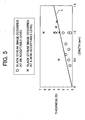
- FIG. 5 is a graph showing a relationship between the diameter (Y) and length (X) of each of filaments of the brush 161Y and an occurrence of black streak image based on experimental results.
- a circle mark indicates that the black streak image occurred at an acceptable level
- a cross mark indicates that the black streak image occurred at a non-acceptable level.
- An approximate line (L) was obtained by determining a plurality of boundary points between the acceptable level and the non-acceptable level and by performing a regression analysis on the determined points.
- the black streak image of a non-acceptable level typically occurred in an area above the level of the approximate line (L).
- the cleaning performance of the brush roller 162Y can be enhanced without increasing the weight of the brush roller 162Y, and thereby the occurrence of the black streak image can be effectively controlled.
- the length of each of the filaments of the brush 161Y rising from the surface of the rotary shaft element 160Y is set approximately 2 mm or less.
- the brush 161Y successfully reduces a bending moment exerted on the base portions of the filaments of the brush 161Y when the brush 161Y elastically bends by abutting the surface of the charging roller 15Y.
- the yield or permanent deformation of the brush 161Y can be controlled over a long time period, so that the useful lifetime of the brush roller 162Y can be extended.
- the brush 161Y is provided on the circumferential surface of the rotary shaft element 160Y such that the density of the filaments of the brush 161Y is approximately 10,000 filaments/cm2 or greater.
- the density of the filaments of the brush 161Y is approximately 10,000 filaments/cm2 or greater.
- the brush roller 162Y satisfies the above-described inequation (1).
- the brush roller 162Y is provided such that each of the filaments of the brush 161Y slants relative to the normal direction in the rotation orbit of the rotary shaft element 160Y as illustrated in FIGs. 6 and 7.
- the normal direction in the rotation orbit of the rotary shaft element 160Y is indicated by dashed lines.
- FIG. 6 illustrates the brush roller 162Y in which each of the filaments of the brush 161Y slants to the upstream side relative to the normal direction in the rotary shaft element 160Y in the moving direction of the surface of the charging roller 15Y. Specifically, as illustrated in FIG.
- FIG. 7 illustrates the brush roller 162Y in which each of the filaments of the brush 161Y slants to the downstream side relative to the normal direction in the rotary shaft element 160Y in the moving direction of the surface of the charging roller 15Y.
- the tip portion thereof is located at the downstream side relative to the normal direction in the rotary shaft element 160Y in the moving direction of the surface of the charging roller 15Y.
- the slant of the filaments of the brush 161Y illustrated in FIG. 6 will be referred to as a "backward slant”
- the slant of the filaments of the brush 161Y illustrated in FIG. 7 will be referred to as a "forward slant”.
- the present inventor conducted experiments by using three kinds of the brush rollers 162Y.
- the first brush roller 162Y includes the filaments of the brush 161Y each of which extends straightly in the normal direction without slanting (hereafter referred to as a "straight brush roller").
- the second brush roller 162Y includes the filaments of the brush 161Y which are backwardly slanted as illustrated in FIG. 6.
- the third brush roller 162Y includes the filaments of the brush 161Y which are forwardly slanted as illustrated in FIG. 7.
- the surface of the charging roller 15Y is forcibly stained by repeatedly printing a reference yellow image having an image area ratio of 25% relative to an A4 size sheet on 5 sheets of A4 size in the laser printer from which the brush roller 162Y is detached.
- the toner density on the surface of the charging roller 15Y was 0.14.
- the toner density was measured by attaching a transparent tape having a thickness of 0.05 mm, such as one sold under the trademark Printac made by Nitto Denko Corporation, to the charging roller 15Y to transfer the residual toner from the charging roller 15Y to the transparent tape.
- the density of the toner on the tape was measured by a reflection densitometer, such as one sold under the trademark X-Rite 508 made by X-Rite Corporation. Then, each of the above-described three brush rollers 162Y was attached to the laser printer, and the above-described reference yellow image was repeatedly printed on the predetermined number of sheets. The density of toner on the charging roller 15Y was measured every time the predetermined number of prints were obtained while using each of the three brush rollers 162Y. In view of necessity for transferring the residual toner from the charging roller 15Y to the transparent tape, the toner density measuring position on the charging roller 15Y was shifted every time the measurement was performed.
- a reflection densitometer such as one sold under the trademark X-Rite 508 made by X-Rite Corporation.
- Each of the three brush rollers 162Y has a weight of about 69 g.
- each of the filaments of the brush 161Y slants relative to the normal direction in the rotary shaft element 160Y by an angle of about 60 to 80 degrees.
- FIG. 8 is a graph showing a relationship between the density (ID) of toner on the charging roller 15Y and the number of prints.
- ID density
- FIG. 8 shows that even if the weight of the three brush rollers 162Y is nearly equal, the density of toner on the charging roller 15Y can be more decreased by using the backward slant and forward slant brush rollers 162Y than the straight brush roller 162Y. This indicates that the cleaning performance of the backward slant and forward slant brush rollers 162Y is superior to that of the straight brush roller 162Y. The reason for this is considered as follows.
- each of the filaments of the brush 161Y of the backward slant brush roller 162Y abuts the surface of the charging roller 15Y while opposing the movement of the surface of the charging roller 15Y.
- the backward slant brush roller 162Y makes great impact on the toner attached onto the surface of the charging roller 15Y.
- the forward slant brush roller 162Y not only the leading edge but also the side surface (i.e., the peripheral surface) of each of the filaments of the brush 161Y contact the surface of the charging roller 15Y, thereby increasing a contact area between the filaments of the brush 161Y and the toner attached onto the surface of the charging roller 15Y.
- the cleaning performance of the backward slant brush roller 162Y is slightly superior to that of the forward slant brush roller 162Y. Therefore, the backward slant brush roller 162Y may be preferably used in view of the cleaning performance.
- the leading edge of each of the filaments of the brush 161Y of the backward slant brush roller 162Y abuts the surface of the charging roller 15Y. In this condition, the surface of the charging roller 15Y may tend to suffer damage.
- the forward slant brush roller 162Y may be preferably used in view of the fact that the reduction of the useful lifetime of the charging roller 15Y can be prevented while enhancing the cleaning performance of the brush roller 162Y.
- Density (ID) of toner on the charging roller Type of brush Left area of roller Center area of roller Right area of roller Straight brush 1.45 1.33 1.48 Forward slant brush 0.93 0.50 0.95 Backward slant brush 0.61 0.30 0.61
- the brush 161Y is made of a conductive material rather than an insulating material, because the conductive brush 161Y exerts higher cleaning performance.
- the present inventor conducted experiments on cleaning performance of the backward slant brush roller 162Y made of an insulating material and the backward slant brush roller 162Y made of a conductive material. Nylon was used as the insulating material. Further, 66 nylon or triacetate in which carbon was dispersed was used as the conductive material. The conditions in this experiment other than the above were similar to the above-described conditions.
- FIG. 9 is a graph showing a relationship between the density of toner on the charging roller 15Y and the number of prints.
- the brush roller 162Y made of the conductive material can control the toner density at a low value over a long period of time, that is, exerts high cleaning performance.
- Density (ID) of toner on the charging roller Type of brush Left area of roller Center area of roller Right area of roller Conductive backward slant brush 0.35 0.0247 0.95 Insulated backward slant brush 0.61 0.30 0.61
- the brush 161Y is made of the conductive material having electric resistivity of approximately 1 X 10 10 ⁇ or less. By using such a conductive material, the brush roller 162 can exert higher cleaning performance rather than an insulating material.
- the laser printer according to the embodiment of the present invention is delivered from a factory in a condition such that a toner accommodating device, such as the developing device 20Y, and the toner cartridge, accommodates toner.
- the toner is charged by friction with a polarity opposite to the polarity of the conductive brush 161Y.
- the brush 161Y is made of a material having a positive charging property, such as Nylon
- the developing device 20Y and the toner cartridge may accommodate toner having a negative charging property for use in an image forming operation in the laser printer.
- the user of the laser printer is requested to use toner that is to be charged by friction with a polarity opposite to the polarity of the conductive brush 161Y.
- the toner attached onto the charging roller 15Y is electrostalically adsorbed to the brush 161Y charged with a polarity opposite to the polarity of the toner, thereby enhancing the cleaning performance of the brush roller 162Y.
- the toner accommodating device may accommodate such toner in advance before delivering the laser printer.
- a production number and a product name of toner may be printed on the main body of the printer or an operation manual.
- the user may be notified of a production number and a product name of toner in writing or electronic data.
- the toner used in the laser printer according to the embodiment of the present invention is prepared by a polymerization method.
- the difference of charging amounts of toner particles between toner particles in a developer is small, so that a charging distribution of toner in a developer narrows.
- the behavior of toner subjected to an electrostatic force, such as a transfer electric field can be uniformalized, thereby enhancing electrostatic transfer efficiency.
- the amount of residual toner remaining on the surface of the photoreceptor 11Y, which has not been transferred onto the transfer conveying belt 60 and which has not been removed therefrom by the counter blade 13Y can be lessened.
- the occurrence of abnormal image caused by the cleaning failure of the brush roller 162Y can be lessened.
- the roller cleaning device, the image forming apparatus and the process unit including the cleaning device have the low-cost and simple configuration without a drive device for driving the brush roller of the cleaning device and a device for regulating an intrusion amount of the brush of the brush roller, and control the permanent deformation of the brush while enhancing cleaning performance of the brush roller.
- the present invention has been described with respect to a laser printer as an example of an image forming apparatus. However, the present invention may be applied to other image forming apparatuses, such as a copying machine, a facsimile machine, etc. or a multi-functional image forming apparatus.
- a mono-color laser printer may also be used.
- the present invention may be applied to an image forming apparatus including one photoreceptor on which toner images of different colors are sequentially formed.
Landscapes
- Physics & Mathematics (AREA)
- General Physics & Mathematics (AREA)
- Engineering & Computer Science (AREA)
- Plasma & Fusion (AREA)
- Electrostatic Charge, Transfer And Separation In Electrography (AREA)
- Cleaning In Electrography (AREA)
Abstract
Description
Specifically, the developing
| Toner | Negatively charged toner prepared by a polymerization method |
| Diameter of the photoreceptor | 30 mm |
| Charging potential of the photoreceptor | -950 V |
| Electric potential of an electrostatic latent image on the photoreceptor | -140 V |
| Developing bias (surface potential of the developing roller) | -650 V |
| Linear velocity of the | 150 mm/sec |
| Diameter of the charging roller | 14 mm |
| Diameter of a | 8 mm |
| of the charging roller | |
| Material of the surface of the charging roller | DPDM (Ethylene Propylene Diene Methylene Linkage) |
| Linear velocity of the charging | 150 mm/sec |
| Charging bias value | -1700 V |
| Diameter of the brush roller | 7.2 mm |
| Diameter of the rotary shaft element of the | 6 mm |
| Length of the filaments of the brush | 0.6 mm |
| Weight of the brush roller | 69 g |
| Angle of the cut-away portion formed in the side plate | 48 degrees |
Subsequently, the density of the toner on the tape was measured by a reflection densitometer, such as one sold under the trademark X-Rite 508 made by X-Rite Corporation. Then, each of the above-described three
| Density (ID) of toner on the charging roller | |||
| Type of brush | Left area of roller | Center area of roller | Right area of roller |
| Straight brush | 1.45 | 1.33 | 1.48 |
| Forward slant brush | 0.93 | 0.50 | 0.95 |
| Backward slant brush | 0.61 | 0.30 | 0.61 |
| Density (ID) of toner on the charging roller | |||
| Type of brush | Left area of roller | Center area of roller | Right area of roller |
| Conductive backward slant brush | 0.35 | 0.0247 | 0.95 |
| Insulated backward slant brush | 0.61 | 0.30 | 0.61 |
Claims (35)
- A cleaning device (16), comprising:wherein the brush includes filaments, and the brush roller satisfies a following inequation,a brush roller (162) configured to remove deposit from a surface of a member (15) to be cleaned while rotating by following a movement of the surface of the member to be cleaned, the brush roller including a rotary shaft element (160) and a brush (161) provided on the rotary shaft element, the brush abutting the surface of the member to be cleaned due to a weight of the brush roller,
- The cleaning device according to claim 1, wherein the length of each of the filaments is at most approximately 2 mm.
- The cleaning device according to claim 1 or 2, wherein a density of the filaments is at least approximately 10,000 filaments/cm2.
- The cleaning device according to one of claims 1-3, wherein the brush is made of a conductive material.
- The cleaning device according to claim 4, wherein the brush has electric resistivity of approximately 1 X 10¹⁰ Ω or less.
- The cleaning device according to one of claims 1-5, wherein the brush is provided on the rotary shaft element such that each of the filaments of the brush slants relative to a normal direction in the rotary shaft element.
- The cleaning device according to claim 6, wherein the brush is provided on the rotary shaft element such that each of the filaments of the brush slants to an upstream side relative to the normal direction in a moving direction of the surface of the member to be cleaned.
- The cleaning device according to claim 6, wherein the brush is provided on the rotary shaft element such that each of the filaments of the brush slants to a downstream side relative to the normal direction in a moving direction of the surface of the member to be cleaned.
- An image forming apparatus, comprising:wherein the brush includes filaments, and the brush roller satisfies a following inequation,an image carrier (11) configured to carry an image on a surface of the image carrier;a charging member (15) configured to charge the surface of the image carrier while contacting the surface of the image carrier;a toner image forming device (1+2) configured to form a toner image on the surface of the image carrier by use of toner; anda cleaning device (16) configured to remove toner attached onto a surface of the charging member, the cleaning device comprising:a brush roller (162) configured to rotate by following a movement of the surface of the charging member, the brush roller including a rotary shaft element (160) and a brush (161) provided on the rotary shaft element, the brush abutting the surface of the charging member due to a weight of the brush roller,
- The image forming apparatus according to claim 9, wherein the length of each of the filaments is at most approximately 2 mm.
- The image forming apparatus according to claim 9 or 10, wherein a density of the filaments is at least approximately 10,000 filaments/cm2.
- The image forming apparatus according to one of claims 9-11, wherein the brush is made of a conductive material.
- The image forming apparatus according to claim 12, wherein the brush has electric resistivity of approximately 1 X 10¹⁰ Ω or less.
- The image forming apparatus according to one of claims 9-13, wherein the brush is provided on the rotary shaft element such that each of the filaments of the brush slants relative to a normal direction in the rotary shaft element.
- The image forming apparatus according to claim 14, wherein the brush is provided on the rotary shaft element such that each of the filaments of the brush slants to an upstream side relative to the normal direction in a moving direction of the surface of the charging member.
- The image forming apparatus according to claim 14, wherein the brush is provided on the rotary shaft element such that each of the filaments of the brush slants to a downstream side relative to the normal direction in a moving direction of the surface of the charging member.
- The image forming apparatus according to one of claims 9-16, further including
a toner accommodating device (20) configured to accommodate the toner used for forming the toner image on the image carrier,
wherein the brush of the brush roller is made of a conductive material and is charged with a predetermined polarity, and
wherein the toner accommodating device accommodates the toner to be charged by friction with a polarity opposite to the polarity of the brush. - The image forming apparatus according to one of claims 9-17,
wherein the brush of the brush roller is made of a conductive material and is charged with a predetermined polarity, and
wherein the toner used for forming the toner image on the image carrier is charged by friction with a polarity opposite to the polarity of the brush. - The image forming apparatus according to one of claims 9-18, wherein the toner used for forming the toner image on the image carrier is prepared by a polymerization method.
- A process unit (10) for use in an image forming apparatus including a latent image carrier (11) configured to carry a latent image on a surface of the latent image carrier, and a developing device (20) configured to develop the latent image on the latent image carrier with toner, the process unit comprising at least:wherein the brush includes filaments, and the brush roller satisfies a following inequation,the latent image carrier;a member (15) to be cleaned that contacts the surface of the latent image carrier;a cleaning device (16) configured to remove toner attached onto a surface of the member to be cleaned, the cleaning device comprising:a brush roller (162) configured to rotate by following a movement of the surface of the member to be cleaned, the brush roller including a rotary shaft element (160) and a brush (161) provided on the rotary shaft element, the brush abutting the surface of the member to be cleaned due to a weight of the brush roller,
- The process unit according to claim 20, wherein the length of each of the filaments is at most approximately 2 mm.
- The process unit according to claim 20 or 21, wherein a density of the filaments is at least approximately 10,000 filaments/cm2.
- The process unit according to one of claims 20-22, wherein the brush is made of a conductive material.
- The process unit according to claim 23, wherein the brush has electric resistivity of approximately 1 X 10¹⁰ Ω or less.
- The process unit according to one of claims 20-24, wherein the brush is provided on the rotary shaft element such that each of the filaments of the brush slants relative to a normal direction in the rotary shaft element.
- The process unit according to claim 25, wherein the brush is provided on the rotary shaft element such that each of the filaments of the brush slants to an upstream side relative to the normal direction in a moving direction of the surface of the member to be cleaned.
- The process unit according to claim 25, wherein the brush is provided on the rotary shaft element such that each of the filaments of the brush slants to a downstream side relative to the normal direction in a moving direction of the surface of the member to be cleaned.
- A method of removing deposit from a surface of a member (15) to be cleaned, comprising steps of:wherein the brush includes filaments, and the brush roller satisfies a following inequation,abutting a brush (161), which is provided on a rotary shaft element (160) of a brush roller (162), against the surface of the member to be cleaned due to a weight of the brush roller; androtating the brush roller by following a movement of the surface of the member to be cleaned,
- The method of according to claim 28, further comprising a step of providing the brush on the rotary shaft element such that each of the filaments of the brush slants relative to a normal direction in the rotary shaft element.
- The method of according to claim 29, wherein the step of providing the brush comprises providing the brush on the rotary shaft element such that each of the filaments of the brush slants to an upstream side relative to the normal direction in a moving direction of the surface of the member to be cleaned.
- The method of according to claim 29, wherein the step of providing the brush comprises providing the brush on the rotary shaft element such that each of the filaments of the brush slants to a downstream side relative to the normal direction in a moving direction of the surface of the member to be cleaned.
- A method of forming an image, comprising steps of:wherein the brush includes filaments, and the brush roller satisfies a following inequation,charging a surface of an image carrier (11) by contacting a charging member (15) with the surface of the image carrier;forming a toner image on the surface of the image carrier; andremoving toner attached onto a surface of the charging member by abutting a brush (161), which is provided on a rotary shaft element (160) of a brush roller (162), against the surface of the charging member due to a weight of the brush roller and by rotating the brush roller by following a movement of the surface of the charging member,
- The method of according to claim 32, wherein the step of removing toner comprises a step of providing the brush on the rotary shaft element such that each of the filaments of the brush slants relative to a normal direction in the rotary shaft element.
- The method of according to claim 33, wherein the step of providing the brush comprises providing the brush on the rotary shaft element such that each of the filaments of the brush slants to an upstream side relative to the normal direction in a moving direction of the surface of the charging member.
- The method of according to claim 33, wherein the step of providing the brush comprises providing the brush on the rotary shaft element such that each of the filaments of the brush slants to a downstream side relative to the normal direction in a moving direction of the surface of the charging member.
Applications Claiming Priority (2)
| Application Number | Priority Date | Filing Date | Title |
|---|---|---|---|
| JP2003169499 | 2003-06-13 | ||
| JP2003169499A JP2005004070A (en) | 2003-06-13 | 2003-06-13 | Cleaning device, image forming apparatus, process unit, cleaning method, and image forming method |
Publications (3)
| Publication Number | Publication Date |
|---|---|
| EP1494088A2 true EP1494088A2 (en) | 2005-01-05 |
| EP1494088A3 EP1494088A3 (en) | 2005-01-19 |
| EP1494088B1 EP1494088B1 (en) | 2011-03-23 |
Family
ID=33432227
Family Applications (1)
| Application Number | Title | Priority Date | Filing Date |
|---|---|---|---|
| EP04013484A Expired - Lifetime EP1494088B1 (en) | 2003-06-13 | 2004-06-08 | Cleaning roller with specific brush filaments, used in an image forming apparatus and process unit for cleaning a contact charger, related methods of removing deposit |
Country Status (5)
| Country | Link |
|---|---|
| US (1) | US7068960B2 (en) |
| EP (1) | EP1494088B1 (en) |
| JP (1) | JP2005004070A (en) |
| CN (1) | CN100347617C (en) |
| DE (1) | DE602004031908D1 (en) |
Families Citing this family (11)
| Publication number | Priority date | Publication date | Assignee | Title |
|---|---|---|---|---|
| US7317883B2 (en) * | 2005-06-27 | 2008-01-08 | Kabushiki Kaisha Toshiba | Color image forming apparatus with at least two stages of image forming units |
| JP4039449B1 (en) * | 2006-08-29 | 2008-01-30 | 富士ゼロックス株式会社 | Cleaning device, process cartridge, and image forming apparatus |
| JP4981389B2 (en) * | 2006-09-13 | 2012-07-18 | キヤノン株式会社 | Image forming apparatus |
| JP2009080392A (en) * | 2007-09-27 | 2009-04-16 | Canon Inc | Image forming apparatus |
| JP2011133688A (en) * | 2009-12-24 | 2011-07-07 | Canon Finetech Inc | Image forming apparatus and brush roller |
| JP5095017B2 (en) * | 2012-03-01 | 2012-12-12 | キヤノン株式会社 | Image forming apparatus |
| JP5634450B2 (en) * | 2012-07-19 | 2014-12-03 | 京セラドキュメントソリューションズ株式会社 | Image forming apparatus |
| JP6318858B2 (en) | 2014-05-27 | 2018-05-09 | 株式会社リコー | Powder conveying apparatus, process cartridge, and image forming apparatus |
| JP2017129764A (en) * | 2016-01-21 | 2017-07-27 | 富士ゼロックス株式会社 | Image formation apparatus |
| CN112971603B (en) * | 2019-12-17 | 2022-01-14 | 宁波方太厨具有限公司 | Thickness-adjustable cleaning head brush bar |
| JP2024098263A (en) | 2023-01-10 | 2024-07-23 | 株式会社リコー | Image forming device |
Family Cites Families (12)
| Publication number | Priority date | Publication date | Assignee | Title |
|---|---|---|---|---|
| JPH0895350A (en) * | 1994-09-28 | 1996-04-12 | Ricoh Co Ltd | Image forming device charging device |
| JP3654560B2 (en) * | 1997-08-18 | 2005-06-02 | 株式会社リコー | Image forming apparatus |
| JPH11167251A (en) * | 1997-10-03 | 1999-06-22 | Ricoh Co Ltd | Image forming apparatus and image forming method |
| JPH11282223A (en) * | 1998-02-02 | 1999-10-15 | Ricoh Co Ltd | Image forming apparatus and optical detection system |
| JP3565709B2 (en) * | 1998-04-10 | 2004-09-15 | 株式会社リコー | Electrophotographic image forming apparatus |
| JP2000122448A (en) * | 1998-10-13 | 2000-04-28 | Ricoh Co Ltd | Image forming device |
| CN1172222C (en) * | 1998-10-14 | 2004-10-20 | 株式会社理光 | Method of controlling toner density and image forming apparatus using the method |
| KR100348374B1 (en) * | 1999-01-14 | 2002-08-10 | 가부시키가이샤 리코 | Image forming apparatus |
| JP3695696B2 (en) * | 2001-01-25 | 2005-09-14 | 株式会社リコー | Cleaning device, unit and image forming apparatus |
| JP4931303B2 (en) * | 2001-09-04 | 2012-05-16 | 株式会社リコー | Cleaning unit and image forming apparatus |
| US6987944B2 (en) * | 2001-03-28 | 2006-01-17 | Ricoh Company, Ltd. | Cleaning device and image forming apparatus using the cleaning device |
| JP3828792B2 (en) * | 2001-11-30 | 2006-10-04 | 矢崎総業株式会社 | Stepping motor movement amount calculation device and stepping motor drive device |
-
2003
- 2003-06-13 JP JP2003169499A patent/JP2005004070A/en active Pending
-
2004
- 2004-06-08 EP EP04013484A patent/EP1494088B1/en not_active Expired - Lifetime
- 2004-06-08 DE DE602004031908T patent/DE602004031908D1/en not_active Expired - Lifetime
- 2004-06-10 CN CNB2004100484608A patent/CN100347617C/en not_active Expired - Fee Related
- 2004-06-10 US US10/864,507 patent/US7068960B2/en not_active Expired - Lifetime
Also Published As
| Publication number | Publication date |
|---|---|
| CN100347617C (en) | 2007-11-07 |
| EP1494088A3 (en) | 2005-01-19 |
| EP1494088B1 (en) | 2011-03-23 |
| CN1573611A (en) | 2005-02-02 |
| DE602004031908D1 (en) | 2011-05-05 |
| US20050019057A1 (en) | 2005-01-27 |
| US7068960B2 (en) | 2006-06-27 |
| JP2005004070A (en) | 2005-01-06 |
Similar Documents
| Publication | Publication Date | Title |
|---|---|---|
| USRE47726E1 (en) | Image forming apparatus | |
| US6701118B2 (en) | Method and apparatus for image forming performing improved cleaning and discharging operations on image forming associated members | |
| US8682208B2 (en) | Cleaning device, image forming apparatus including same, and method for mounting same | |
| US7539442B2 (en) | Charging unit, process unit including the same, and image forming apparatus including the same | |
| US7778573B2 (en) | Image forming apparatus and process cartridge | |
| US8406664B2 (en) | Image forming apparatus, image forming method, and developing device | |
| US9395656B2 (en) | Transfer unit and image forming apparatus employing the transfer unit | |
| US20080038017A1 (en) | Method and apparatus for image forming for effectively charging an image carrier | |
| JP2004021188A (en) | Image forming apparatus | |
| EP1494088B1 (en) | Cleaning roller with specific brush filaments, used in an image forming apparatus and process unit for cleaning a contact charger, related methods of removing deposit | |
| US7903993B2 (en) | Image forming apparatus | |
| US7937017B2 (en) | Image forming apparatus | |
| US9008546B2 (en) | Image carrier, process cartridge, and image forming apparatus | |
| US9541865B2 (en) | Image forming apparatus with a controller to control an alternating transfer bias | |
| US20200233365A1 (en) | Cleaning device, process cartridge, and image forming apparatus | |
| JP5347822B2 (en) | Exposure apparatus and image forming apparatus | |
| US7317884B2 (en) | Image forming apparatus featuring a defined relationship among an image length, transforming member length, and length of an electric field area | |
| US7787800B2 (en) | Belt cleaning device and image forming apparatus including the same | |
| US6912369B2 (en) | Image forming apparatus | |
| US20260064045A1 (en) | Cleaning device and image forming apparatus | |
| JP3826565B2 (en) | Image forming apparatus | |
| JPH10207247A (en) | Image forming device | |
| KR101029069B1 (en) | Electrophotographic image forming apparatus | |
| JP2021192078A (en) | Image forming apparatus and image forming method |
Legal Events
| Date | Code | Title | Description |
|---|---|---|---|
| PUAI | Public reference made under article 153(3) epc to a published international application that has entered the european phase |
Free format text: ORIGINAL CODE: 0009012 |
|
| PUAL | Search report despatched |
Free format text: ORIGINAL CODE: 0009013 |
|
| AK | Designated contracting states |
Kind code of ref document: A2 Designated state(s): AT BE BG CH CY CZ DE DK EE ES FI FR GB GR HU IE IT LI LU MC NL PL PT RO SE SI SK TR |
|
| AX | Request for extension of the european patent |
Extension state: AL HR LT LV MK |
|
| AK | Designated contracting states |
Kind code of ref document: A3 Designated state(s): AT BE BG CH CY CZ DE DK EE ES FI FR GB GR HU IE IT LI LU MC NL PL PT RO SE SI SK TR |
|
| AX | Request for extension of the european patent |
Extension state: AL HR LT LV MK |
|
| 17P | Request for examination filed |
Effective date: 20050211 |
|
| AKX | Designation fees paid |
Designated state(s): AT BE BG |
|
| RBV | Designated contracting states (corrected) |
Designated state(s): DE FR GB |
|
| REG | Reference to a national code |
Ref country code: DE Ref legal event code: 8566 |
|
| 17Q | First examination report despatched |
Effective date: 20071123 |
|
| GRAP | Despatch of communication of intention to grant a patent |
Free format text: ORIGINAL CODE: EPIDOSNIGR1 |
|
| GRAS | Grant fee paid |
Free format text: ORIGINAL CODE: EPIDOSNIGR3 |
|
| GRAA | (expected) grant |
Free format text: ORIGINAL CODE: 0009210 |
|
| AK | Designated contracting states |
Kind code of ref document: B1 Designated state(s): DE FR GB |
|
| REG | Reference to a national code |
Ref country code: GB Ref legal event code: FG4D |
|
| REF | Corresponds to: |
Ref document number: 602004031908 Country of ref document: DE Date of ref document: 20110505 Kind code of ref document: P |
|
| REG | Reference to a national code |
Ref country code: DE Ref legal event code: R096 Ref document number: 602004031908 Country of ref document: DE Effective date: 20110505 |
|
| PLBE | No opposition filed within time limit |
Free format text: ORIGINAL CODE: 0009261 |
|
| STAA | Information on the status of an ep patent application or granted ep patent |
Free format text: STATUS: NO OPPOSITION FILED WITHIN TIME LIMIT |
|
| 26N | No opposition filed |
Effective date: 20111227 |
|
| REG | Reference to a national code |
Ref country code: DE Ref legal event code: R097 Ref document number: 602004031908 Country of ref document: DE Effective date: 20111227 |
|
| REG | Reference to a national code |
Ref country code: FR Ref legal event code: PLFP Year of fee payment: 13 |
|
| REG | Reference to a national code |
Ref country code: FR Ref legal event code: PLFP Year of fee payment: 14 |
|
| PGFP | Annual fee paid to national office [announced via postgrant information from national office to epo] |
Ref country code: FR Payment date: 20170621 Year of fee payment: 14 Ref country code: GB Payment date: 20170620 Year of fee payment: 14 Ref country code: DE Payment date: 20170621 Year of fee payment: 14 |
|
| REG | Reference to a national code |
Ref country code: DE Ref legal event code: R119 Ref document number: 602004031908 Country of ref document: DE |
|
| GBPC | Gb: european patent ceased through non-payment of renewal fee |
Effective date: 20180608 |
|
| PG25 | Lapsed in a contracting state [announced via postgrant information from national office to epo] |
Ref country code: GB Free format text: LAPSE BECAUSE OF NON-PAYMENT OF DUE FEES Effective date: 20180608 Ref country code: FR Free format text: LAPSE BECAUSE OF NON-PAYMENT OF DUE FEES Effective date: 20180630 Ref country code: DE Free format text: LAPSE BECAUSE OF NON-PAYMENT OF DUE FEES Effective date: 20190101 |