EP1493925A1 - Compressor unit and refrigerator using the unit - Google Patents
Compressor unit and refrigerator using the unit Download PDFInfo
- Publication number
- EP1493925A1 EP1493925A1 EP03745976A EP03745976A EP1493925A1 EP 1493925 A1 EP1493925 A1 EP 1493925A1 EP 03745976 A EP03745976 A EP 03745976A EP 03745976 A EP03745976 A EP 03745976A EP 1493925 A1 EP1493925 A1 EP 1493925A1
- Authority
- EP
- European Patent Office
- Prior art keywords
- inverter
- compressor
- current
- ambient temperature
- over
- Prior art date
- Legal status (The legal status is an assumption and is not a legal conclusion. Google has not performed a legal analysis and makes no representation as to the accuracy of the status listed.)
- Withdrawn
Links
- 230000001681 protective effect Effects 0.000 claims abstract description 35
- 238000010586 diagram Methods 0.000 description 4
- 239000003507 refrigerant Substances 0.000 description 3
- 238000009825 accumulation Methods 0.000 description 2
- 230000003213 activating effect Effects 0.000 description 2
- 230000004913 activation Effects 0.000 description 2
- 239000007788 liquid Substances 0.000 description 2
- 238000005259 measurement Methods 0.000 description 2
- 239000003990 capacitor Substances 0.000 description 1
- 230000007423 decrease Effects 0.000 description 1
- 238000009499 grossing Methods 0.000 description 1
- 230000006698 induction Effects 0.000 description 1
Images


Classifications
-
- F—MECHANICAL ENGINEERING; LIGHTING; HEATING; WEAPONS; BLASTING
- F04—POSITIVE - DISPLACEMENT MACHINES FOR LIQUIDS; PUMPS FOR LIQUIDS OR ELASTIC FLUIDS
- F04B—POSITIVE-DISPLACEMENT MACHINES FOR LIQUIDS; PUMPS
- F04B49/00—Control, e.g. of pump delivery, or pump pressure of, or safety measures for, machines, pumps, or pumping installations, not otherwise provided for, or of interest apart from, groups F04B1/00 - F04B47/00
- F04B49/10—Other safety measures
-
- F—MECHANICAL ENGINEERING; LIGHTING; HEATING; WEAPONS; BLASTING
- F04—POSITIVE - DISPLACEMENT MACHINES FOR LIQUIDS; PUMPS FOR LIQUIDS OR ELASTIC FLUIDS
- F04B—POSITIVE-DISPLACEMENT MACHINES FOR LIQUIDS; PUMPS
- F04B49/00—Control, e.g. of pump delivery, or pump pressure of, or safety measures for, machines, pumps, or pumping installations, not otherwise provided for, or of interest apart from, groups F04B1/00 - F04B47/00
- F04B49/06—Control using electricity
- F04B49/065—Control using electricity and making use of computers
-
- F—MECHANICAL ENGINEERING; LIGHTING; HEATING; WEAPONS; BLASTING
- F04—POSITIVE - DISPLACEMENT MACHINES FOR LIQUIDS; PUMPS FOR LIQUIDS OR ELASTIC FLUIDS
- F04B—POSITIVE-DISPLACEMENT MACHINES FOR LIQUIDS; PUMPS
- F04B49/00—Control, e.g. of pump delivery, or pump pressure of, or safety measures for, machines, pumps, or pumping installations, not otherwise provided for, or of interest apart from, groups F04B1/00 - F04B47/00
-
- F—MECHANICAL ENGINEERING; LIGHTING; HEATING; WEAPONS; BLASTING
- F04—POSITIVE - DISPLACEMENT MACHINES FOR LIQUIDS; PUMPS FOR LIQUIDS OR ELASTIC FLUIDS
- F04B—POSITIVE-DISPLACEMENT MACHINES FOR LIQUIDS; PUMPS
- F04B2203/00—Motor parameters
- F04B2203/02—Motor parameters of rotating electric motors
- F04B2203/0201—Current
-
- F—MECHANICAL ENGINEERING; LIGHTING; HEATING; WEAPONS; BLASTING
- F04—POSITIVE - DISPLACEMENT MACHINES FOR LIQUIDS; PUMPS FOR LIQUIDS OR ELASTIC FLUIDS
- F04B—POSITIVE-DISPLACEMENT MACHINES FOR LIQUIDS; PUMPS
- F04B2203/00—Motor parameters
- F04B2203/02—Motor parameters of rotating electric motors
- F04B2203/0202—Voltage
-
- F—MECHANICAL ENGINEERING; LIGHTING; HEATING; WEAPONS; BLASTING
- F04—POSITIVE - DISPLACEMENT MACHINES FOR LIQUIDS; PUMPS FOR LIQUIDS OR ELASTIC FLUIDS
- F04B—POSITIVE-DISPLACEMENT MACHINES FOR LIQUIDS; PUMPS
- F04B2205/00—Fluid parameters
- F04B2205/10—Inlet temperature
Definitions
- the present invention relates to a compressor unit and a refrigerator using the unit.
- the compressor unit has a compressor, an inverter for driving the compressor, and an over-current protective device for protecting the inverter against an output over-current.
- an inverter output voltage is set according to a working current value of the over-current protective device. That is, the inverter output voltage is set so that an inverter output current does not exceed the working current value of the over-current protective device and so that a maximum starting torque is gained.
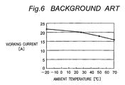
- the over-current protective device has characteristics in which a high ambient temperature decreases the working current value and in which a low ambient temperature increases the working current value, as shown in Fig. 6.
- the present invention provides a compressor unit comprising a compressor, an inverter for driving the compressor, and an over-current protective device for protecting the inverter against an output over-current, the compressor unit characterized in that a working current value of the over-current protective device has temperature characteristics varying according to an ambient temperature, the compressor unit further comprising:
- the compressor is started by an inverter output voltage such that an output current or an input current of the inverter, for example, which is compared with the working current value does not exceed the working current value corresponding to the ambient temperature and thus the inverter output voltage can be increased without activating the over-current protective device when the compressor is started at a low temperature when a start load is increased, so that the start of the compressor can be facilitated by increase in a starting torque.
- control part determines the inverter output voltage on occasion of the start on basis of the ambient temperature detected by the temperature sensor so that an output current or an input current of the inverter is smaller than and in vicinity of the working current value of the over-current protective device corresponding to the ambient temperature detected by the temperature sensor.
- the inverter output voltage resulting in the output current or the input current of the inverter that is smaller than and in vicinity of the working current value of the over-current protective device corresponding to the ambient temperature detected by the temperature sensor is determined on basis of the ambient temperature detected by the temperature sensor. Therefore, the inverter output voltage on occasion of the start can be made as high as possible in accordance with the temperature characteristics of the working current value of the over-current protective device.
- the working current value of the over-current protective device has temperature characteristics in which the lower ambient temperature results in the larger working current value and in which the higher ambient temperature results in the smaller working current value
- the control part determines the inverter output voltage on occasion of the start on basis of the ambient temperature detected by the temperature sensor so that the lower the ambient temperature detected by the temperature sensor is, the higher the inverter output voltage on occasion of the start is and so that the higher the ambient temperature detected by the temperature sensor is, the lower the inverter output voltage on occasion of the start is.
- the lower ambient temperature detected by the temperature sensor is, the higher the inverter output voltage on occasion of the start is made, and the higher the ambient temperature detected by the temperature sensor is, the lower the inverter output voltage on occasion of the start is made.
- the inverter output voltage on occasion of the start can be made as high as possible in accordance with the temperature characteristics of the working current value of the over-current protective device.
- a refrigerator of the invention is characterized in that the refrigerator includes the compressor unit.
- the inverter output voltage can be increased without activating the over-current protective device on occasion of start at a low temperature when a start load is increased, so that the start of the compressor can be facilitated by increase in a starting torque.
- Fig. 1 is a schematic configuration of a compressor unit for use in an air conditioner in accordance with an embodiment of the invention.
- the compressor unit has a rectifying circuit 1 to which an AC power supply (not shown) is connected, an inverter 2 for converting a DC voltage from the rectifying circuit 1 into an AC voltage, and a compressor 3 that is driven by an output voltage from the inverter 2.
- An output terminal on a positive electrode side of the rectifying circuit 1 is connected to one input terminal of the inverter 2, and an output terminal on a negative electrode side of the rectifying circuit 1 is connected through a current shunt resistor 4 to the other input terminal of the inverter 2.
- a smoothing capacitor C Between both the output terminals of the rectifying circuit 1 is connected a smoothing capacitor C.
- One end of the current shunt resistor 4 on a side of the inverter 2 is connected through a resistor R 1 to one input terminal (on an anode side of a built-in light emitting diode) of a photocoupler 5, and the other end of the current shunt resistor 4 on a side of the rectifying circuit 1 is connected to the other input terminal (on a cathode side of the built-in light emitting diode) of the photocoupler 5. Between both the input terminals of the photocoupler 5 is connected a resistor R 2 .
- One output terminal (on a collector side of a built-in output transistor) of the photocoupler 5 is connected through a resistor R 3 to an input terminal of a control part 6, and the other output terminal (on an emitter side of the built-in output transistor) of the photocoupler 5 is connected to a ground.
- a temperature sensor 7 for detecting an ambient temperature is connected to an input terminal of the control part 6.
- the control part 6 is composed of a microcomputer, an input-output circuit, and the like, and controls the output voltage of the inverter 2.
- the shunt resistor 4, the photocoupler 5, and the resistors R 1 to R 4 form an over-current protective device.
- an input current for the inverter 2 becomes larger than a specified current while the compressor 3 is operated by the inverter 2
- a voltage across the current shunt resistor 4 is increased and the photocoupler 5 is turned on so that activation of the over-current protective device is notified to the control part 2.
- the control part 2 turns off or reduces the output voltage of the inverter 2 and thereby prevents damage to the inverter 2 that may result from an output over-current.
- working current values vary according to a temperature characteristic of the photocoupler 5.
- the temperature characteristic as shown in Fig. 6, the lower an ambient temperature is, the larger the working current value is; the higher the ambient temperature is, the smaller the working current value is.
- the control part 6 is activated to control the output voltage of the inverter 2 in accordance with a flowchart of Fig. 2.
- Fig. 2 an ambient temperature is detected by the temperature sensor 7 in a step S1.
- the processing subsequently goes to a step S2, and an output voltage of the inverter 2 is selected in accordance with the ambient temperature detected by the temperature sensor 7.
- the processing then goes to a step S3, and the output voltage selected in the step S2 is outputted from the inverter 2 so as to drive the compressor 3.
- a temperature of electrical equipment (not shown) is preferably detected but a temperature of outside air, a discharge pipe of the compressor 3, a heat exchanger, a radiating fin (for power transistors of the inverter) or the like may be used.
- an inverter output voltage that comes short of the working current value is predetermined for each value of the ambient temperature on basis of the temperature characteristic (shown in Fig. 6) of the working current value of the over-current protective device. That is, a relation between the inverter output voltages and the ambient temperatures is made similar to the temperature characteristic of the working current value of the over-current protective device.
- inverter output voltages may be determined so as to have a linear characteristic expressed by a linear expression approximate to a curve that shows a relation between the inverter output voltages and the ambient temperatures or, as shown in Fig.
- an inverter output voltage may be determined for every certain range of the temperature.
- the inverter output voltage on occasion of the start is determined so that the input current for the inverter 2 is smaller than and in vicinity of a working current value of the over-current protective device corresponding to the ambient temperature detected by the temperature sensor 7.
- the inverter output voltage that has been determined as described above may be outputted fully on occasion of the start of the compressor 3 or, as shown in Fig. 4, the output voltage may be increased gradually from a voltage lower than the determined inverter output voltage.
- a period of time for which the initial voltage on occasion of the start of the compressor 3 is outputted corresponds to a period of time that elapses until a motor in the compressor 3 starts rotating and therefore may be short, i.e., on the order of 100 msec. Extension of the period of time according to circumstances is, however, effective for addressing increase in oil viscosity, accumulation of liquid refrigerant or the like on occasion of the start at low temperature.
- VF characteristic linear characteristic
- inverter output voltage is determined in accordance with the VF characteristic.
- a change in the initial inverter output voltage in accordance with ambient temperatures causes a deviation from the VF characteristic.
- the VF characteristic is switched to lines that link an inverter output voltage d corresponding to a frequency f 2 (outside an operating range of the compressor 3) and the inverter output voltages a, b, and c corresponding to the frequency f 1 .
- the deviation that occurs between the inverter output voltages changed in accordance with initial ambient temperatures and the VF characteristic is resolved.
- the compressor unit of the invention may be used not only for air conditioners but for other refrigerators.
- the inverter input current detected by the shunt resistor 4 has a pulse shape
- the inverter output current that flows from the three-phase AC voltage output inverter 2 to the compressor 3 has an AC waveform.
- a peak value of the inverter output current is generally as large as a peak value of the inverter input current that is detected by the shunt resistor 4 and that has the pulse shape.
- a peak value of a motor current can be found by the shunt resistor 4.
- the shunt resistor 4 is provided on a negative electrode side of the inverter 2 in the embodiment, the shunt resistor may be provided on a positive electrode side of the inverter in order to detect the inverter input current.
- the over-current protective device composed of the shunt resistor 4, the photocoupler 5, and the resistors R 1 to R 4
- the over-current protective device is not limited thereto, and there may be used over-current protective devices having other configurations or having different temperature characteristics of working current value.
- Over-current protection in the embodiment is performed with use of the input current for the inverter 2 that is detected by the shunt resistor 4; however, current detecting means may be provided on the output side of the inverter and the protection may be performed with use of the inverter output current detected by the current detecting means.
- the current is detected on the negative electrode side because current measurement on the positive electrode side of the inverter increases a drift (floating) of the current value and because current measurement on the output side of the inverter requires a complicated detecting circuit.
Landscapes
- Engineering & Computer Science (AREA)
- Mechanical Engineering (AREA)
- General Engineering & Computer Science (AREA)
- Computer Hardware Design (AREA)
- Inverter Devices (AREA)
- Control Of Ac Motors In General (AREA)
- Control Of Positive-Displacement Pumps (AREA)
Abstract
Description
the compressor unit characterized in that a working current value of the over-current protective device has temperature characteristics varying according to an ambient temperature,
the compressor unit further comprising:
wherein the control part determines the inverter output voltage on occasion of the start on basis of the ambient temperature detected by the temperature sensor so that the lower the ambient temperature detected by the temperature sensor is, the higher the inverter output voltage on occasion of the start is and so that the higher the ambient temperature detected by the temperature sensor is, the lower the inverter output voltage on occasion of the start is.
Claims (4)
- A compressor unit comprising a compressor (3), an inverter (2) for driving the compressor (3), and an over-current protective device for protecting the inverter (2) against an output over-current,
the compressor unit characterized in that a working current value of the over-current protective device has temperature characteristics varying according to an ambient temperature,
the compressor unit further comprising:a temperature sensor (7) for detecting the ambient temperature, anda control part (6) for controlling an output voltage of the inverter (2) on occasion of start of the compressor (3) on basis of the ambient temperature detected by the temperature sensor (7). - A compressor unit as claimed in claim 1, wherein the control part (6) determines the inverter output voltage on occasion of the start on basis of the ambient temperature detected by the temperature sensor (7) so that an output current or an input current of the inverter (2) is smaller than and in vicinity of the working current value of the over-current protective device corresponding to the ambient temperature detected by the temperature sensor (7).
- A compressor unit as claimed in claim 1 or 2,
wherein the working current value of the over-current protective device has temperature characteristics in which the lower ambient temperature results in the larger working current value and in which the higher ambient temperature results in the smaller working current value, and
wherein the control part (6) determines the inverter output voltage on occasion of the start on basis of the ambient temperature detected by the temperature sensor (7) so that the lower the ambient temperature detected by the temperature sensor (7) is, the higher the inverter output voltage on occasion of the start is and so that the higher the ambient temperature detected by the temperature sensor (7) is, the lower the inverter output voltage on occasion of the start is. - A refrigerator including the compressor unit as claimed in any one of claims 1 through 3.
Applications Claiming Priority (3)
| Application Number | Priority Date | Filing Date | Title |
|---|---|---|---|
| JP2002108117 | 2002-04-10 | ||
| JP2002108117 | 2002-04-10 | ||
| PCT/JP2003/004474 WO2003085265A1 (en) | 2002-04-10 | 2003-04-09 | Compressor unit and refrigerator using the unit |
Publications (2)
| Publication Number | Publication Date |
|---|---|
| EP1493925A1 true EP1493925A1 (en) | 2005-01-05 |
| EP1493925A4 EP1493925A4 (en) | 2008-09-10 |
Family
ID=28786500
Family Applications (1)
| Application Number | Title | Priority Date | Filing Date |
|---|---|---|---|
| EP03745976A Withdrawn EP1493925A4 (en) | 2002-04-10 | 2003-04-09 | COMPRESSOR AND REFRIGERATOR GROUP USING SUCH A GROUP |
Country Status (7)
| Country | Link |
|---|---|
| US (1) | US7134295B2 (en) |
| EP (1) | EP1493925A4 (en) |
| JP (1) | JP4175258B2 (en) |
| KR (1) | KR100594515B1 (en) |
| CN (1) | CN100376853C (en) |
| AU (1) | AU2003236004B2 (en) |
| WO (1) | WO2003085265A1 (en) |
Families Citing this family (21)
| Publication number | Priority date | Publication date | Assignee | Title |
|---|---|---|---|---|
| US7412842B2 (en) | 2004-04-27 | 2008-08-19 | Emerson Climate Technologies, Inc. | Compressor diagnostic and protection system |
| US7275377B2 (en) | 2004-08-11 | 2007-10-02 | Lawrence Kates | Method and apparatus for monitoring refrigerant-cycle systems |
| US8590325B2 (en) | 2006-07-19 | 2013-11-26 | Emerson Climate Technologies, Inc. | Protection and diagnostic module for a refrigeration system |
| US20080216494A1 (en) * | 2006-09-07 | 2008-09-11 | Pham Hung M | Compressor data module |
| JP4939171B2 (en) * | 2006-10-30 | 2012-05-23 | 三菱重工業株式会社 | Heat source machine and heat source system |
| EP2137409A4 (en) * | 2007-03-13 | 2013-05-01 | Carrier Corp | Compressor reverse rotation of variable duration on start up |
| JP5043521B2 (en) * | 2007-06-06 | 2012-10-10 | サンデン株式会社 | Control device for electric compressor |
| US20090037142A1 (en) | 2007-07-30 | 2009-02-05 | Lawrence Kates | Portable method and apparatus for monitoring refrigerant-cycle systems |
| US8393169B2 (en) | 2007-09-19 | 2013-03-12 | Emerson Climate Technologies, Inc. | Refrigeration monitoring system and method |
| US8160827B2 (en) | 2007-11-02 | 2012-04-17 | Emerson Climate Technologies, Inc. | Compressor sensor module |
| US9140728B2 (en) | 2007-11-02 | 2015-09-22 | Emerson Climate Technologies, Inc. | Compressor sensor module |
| CN102193604B (en) * | 2010-03-16 | 2014-03-26 | 鸿富锦精密工业(深圳)有限公司 | Heat-radiation circuit of CPU (Central Processing Unit) |
| CN103597292B (en) | 2011-02-28 | 2016-05-18 | 艾默生电气公司 | Monitoring system and monitoring method for a heating, ventilation and air conditioning HVAC system of a building |
| US8964338B2 (en) | 2012-01-11 | 2015-02-24 | Emerson Climate Technologies, Inc. | System and method for compressor motor protection |
| US9480177B2 (en) | 2012-07-27 | 2016-10-25 | Emerson Climate Technologies, Inc. | Compressor protection module |
| US9310439B2 (en) | 2012-09-25 | 2016-04-12 | Emerson Climate Technologies, Inc. | Compressor having a control and diagnostic module |
| US9803902B2 (en) | 2013-03-15 | 2017-10-31 | Emerson Climate Technologies, Inc. | System for refrigerant charge verification using two condenser coil temperatures |
| EP2971989A4 (en) | 2013-03-15 | 2016-11-30 | Emerson Electric Co | DIAGNOSTICS AND SYSTEM FOR HEATING, VENTILATION AND AIR CONDITIONING REMOTE MONITORING |
| US9551504B2 (en) | 2013-03-15 | 2017-01-24 | Emerson Electric Co. | HVAC system remote monitoring and diagnosis |
| WO2014165731A1 (en) | 2013-04-05 | 2014-10-09 | Emerson Electric Co. | Heat-pump system with refrigerant charge diagnostics |
| US11728757B2 (en) | 2019-11-07 | 2023-08-15 | Carrier Corporation | System and method for controlling temperature inside electrical and electronics system |
Family Cites Families (11)
| Publication number | Priority date | Publication date | Assignee | Title |
|---|---|---|---|---|
| US4179899A (en) * | 1977-06-24 | 1979-12-25 | Sawafuji Electric Co. Ltd. | Refrigerating system |
| JPS62178832A (en) * | 1986-02-03 | 1987-08-05 | Hitachi Ltd | Control circuit for air conditioner with inverter |
| US4893479A (en) * | 1987-03-20 | 1990-01-16 | Ranco Electronics Division | Compressor drive system |
| CN2059977U (en) * | 1989-11-18 | 1990-08-01 | 魏晓云 | Multifunctional electronic temp. controller of refrigerator for temp. setting and restoring |
| JPH04313645A (en) * | 1991-04-11 | 1992-11-05 | Toshiba Corp | Refrigeration cycle device |
| JPH0513562A (en) * | 1991-07-05 | 1993-01-22 | Hitachi Ltd | Drive controller |
| JPH06193945A (en) * | 1992-12-24 | 1994-07-15 | Matsushita Electric Ind Co Ltd | Control device for air conditioner |
| CN2181660Y (en) * | 1993-12-25 | 1994-11-02 | 唐山市普发电子技术开发公司 | Intelligent frequency-change refrigerating unit |
| JP3327053B2 (en) * | 1995-06-06 | 2002-09-24 | 株式会社デンソー | Air conditioner |
| JPH1114124A (en) * | 1997-06-20 | 1999-01-22 | Sharp Corp | Air conditioner |
| JP2000227074A (en) * | 1999-02-04 | 2000-08-15 | Matsushita Electric Ind Co Ltd | Compressor drive control method and device |
-
2003
- 2003-04-09 US US10/504,877 patent/US7134295B2/en not_active Expired - Fee Related
- 2003-04-09 EP EP03745976A patent/EP1493925A4/en not_active Withdrawn
- 2003-04-09 WO PCT/JP2003/004474 patent/WO2003085265A1/en not_active Ceased
- 2003-04-09 CN CNB038054396A patent/CN100376853C/en not_active Expired - Fee Related
- 2003-04-09 AU AU2003236004A patent/AU2003236004B2/en not_active Ceased
- 2003-04-09 KR KR1020047013188A patent/KR100594515B1/en not_active Expired - Fee Related
- 2003-04-09 JP JP2003582419A patent/JP4175258B2/en not_active Expired - Fee Related
Also Published As
| Publication number | Publication date |
|---|---|
| US7134295B2 (en) | 2006-11-14 |
| CN1639465A (en) | 2005-07-13 |
| JPWO2003085265A1 (en) | 2005-08-11 |
| WO2003085265A1 (en) | 2003-10-16 |
| KR20040088528A (en) | 2004-10-16 |
| AU2003236004A1 (en) | 2003-10-20 |
| JP4175258B2 (en) | 2008-11-05 |
| KR100594515B1 (en) | 2006-06-30 |
| US20050103036A1 (en) | 2005-05-19 |
| AU2003236004B2 (en) | 2008-06-19 |
| EP1493925A4 (en) | 2008-09-10 |
| CN100376853C (en) | 2008-03-26 |
Similar Documents
| Publication | Publication Date | Title |
|---|---|---|
| US7134295B2 (en) | Compressor unit and refrigerator using the unit | |
| US4736595A (en) | Circuit for controlling inventer in air conditioner | |
| US6665200B2 (en) | Air conditioner including a control unit powered by a switching power supply | |
| EP2140213B1 (en) | Refrigerator and operating method thereof | |
| JPH06101895A (en) | Inverter control device for air conditioner | |
| KR100983932B1 (en) | controller | |
| US6949899B2 (en) | Brushless DC motor having an AC power control device | |
| US6657408B2 (en) | Air conditioner | |
| JPH0970178A (en) | Air conditioner | |
| KR102266356B1 (en) | Power converting device with function for protection circuit and totem-pole pfc | |
| JP3314852B2 (en) | Operation control device for air conditioner | |
| KR100308563B1 (en) | Outdoor unit power supply and method of the separate air conditioner | |
| KR102060069B1 (en) | Power transforming apparatus, Method for controlling the same and Air conditioner including the power transforming apparatus | |
| GB2427041A (en) | Torque control device for electrical tools | |
| US7068000B1 (en) | Torque control device for electrical tools | |
| KR0177691B1 (en) | Control method of compressor operation of inverter air conditioner | |
| KR102746363B1 (en) | Motor-driven compressor for vehicle | |
| KR20070030073A (en) | Drive device of inverter air conditioner and its control method | |
| KR20040032575A (en) | method for controlling aircon of vehicle | |
| KR20050014287A (en) | Noise preventing device for air conditioner and method for the same | |
| JPH11332248A (en) | Storage type air conditioner | |
| KR100199964B1 (en) | Heating control method of air conditioner and power transistor of air conditioner | |
| KR20080064019A (en) | Air conditioner | |
| JP2021027762A (en) | Power conversion device | |
| JPS60144154A (en) | High efficiency operating device of air conditioner |
Legal Events
| Date | Code | Title | Description |
|---|---|---|---|
| PUAI | Public reference made under article 153(3) epc to a published international application that has entered the european phase |
Free format text: ORIGINAL CODE: 0009012 |
|
| 17P | Request for examination filed |
Effective date: 20040910 |
|
| AK | Designated contracting states |
Kind code of ref document: A1 Designated state(s): AT BE BG CH CY CZ DE DK EE ES FI FR GB GR HU IE IT LI LU MC NL PT RO SE SI SK TR |
|
| AX | Request for extension of the european patent |
Extension state: AL LT LV MK |
|
| A4 | Supplementary search report drawn up and despatched |
Effective date: 20080811 |
|
| GRAP | Despatch of communication of intention to grant a patent |
Free format text: ORIGINAL CODE: EPIDOSNIGR1 |
|
| STAA | Information on the status of an ep patent application or granted ep patent |
Free format text: STATUS: THE APPLICATION IS DEEMED TO BE WITHDRAWN |
|
| 18D | Application deemed to be withdrawn |
Effective date: 20110219 |