EP1493614A2 - Child seat - Google Patents
Child seat Download PDFInfo
- Publication number
- EP1493614A2 EP1493614A2 EP04015379A EP04015379A EP1493614A2 EP 1493614 A2 EP1493614 A2 EP 1493614A2 EP 04015379 A EP04015379 A EP 04015379A EP 04015379 A EP04015379 A EP 04015379A EP 1493614 A2 EP1493614 A2 EP 1493614A2
- Authority
- EP
- European Patent Office
- Prior art keywords
- seat
- base unit
- belt
- waist belt
- slider
- Prior art date
- Legal status (The legal status is an assumption and is not a legal conclusion. Google has not performed a legal analysis and makes no representation as to the accuracy of the status listed.)
- Withdrawn
Links
Images







Classifications
-
- B—PERFORMING OPERATIONS; TRANSPORTING
- B60—VEHICLES IN GENERAL
- B60N—SEATS SPECIALLY ADAPTED FOR VEHICLES; VEHICLE PASSENGER ACCOMMODATION NOT OTHERWISE PROVIDED FOR
- B60N2/00—Seats specially adapted for vehicles; Arrangement or mounting of seats in vehicles
- B60N2/24—Seats specially adapted for vehicles; Arrangement or mounting of seats in vehicles for particular purposes or particular vehicles
- B60N2/26—Seats specially adapted for vehicles; Arrangement or mounting of seats in vehicles for particular purposes or particular vehicles for children
- B60N2/28—Seats readily mountable on, and dismountable from, existing seats or other parts of the vehicle
- B60N2/2821—Seats readily mountable on, and dismountable from, existing seats or other parts of the vehicle having a seat and a base part
-
- B—PERFORMING OPERATIONS; TRANSPORTING
- B60—VEHICLES IN GENERAL
- B60N—SEATS SPECIALLY ADAPTED FOR VEHICLES; VEHICLE PASSENGER ACCOMMODATION NOT OTHERWISE PROVIDED FOR
- B60N2/00—Seats specially adapted for vehicles; Arrangement or mounting of seats in vehicles
- B60N2/24—Seats specially adapted for vehicles; Arrangement or mounting of seats in vehicles for particular purposes or particular vehicles
- B60N2/26—Seats specially adapted for vehicles; Arrangement or mounting of seats in vehicles for particular purposes or particular vehicles for children
- B60N2/28—Seats readily mountable on, and dismountable from, existing seats or other parts of the vehicle
- B60N2/2803—Adaptations for seat belts
- B60N2/2806—Adaptations for seat belts for securing the child seat to the vehicle
-
- B—PERFORMING OPERATIONS; TRANSPORTING
- B60—VEHICLES IN GENERAL
- B60N—SEATS SPECIALLY ADAPTED FOR VEHICLES; VEHICLE PASSENGER ACCOMMODATION NOT OTHERWISE PROVIDED FOR
- B60N2/00—Seats specially adapted for vehicles; Arrangement or mounting of seats in vehicles
- B60N2/24—Seats specially adapted for vehicles; Arrangement or mounting of seats in vehicles for particular purposes or particular vehicles
- B60N2/26—Seats specially adapted for vehicles; Arrangement or mounting of seats in vehicles for particular purposes or particular vehicles for children
- B60N2/28—Seats readily mountable on, and dismountable from, existing seats or other parts of the vehicle
- B60N2/2803—Adaptations for seat belts
- B60N2/2812—Adaptations for seat belts for securing the child to the child seat
-
- B—PERFORMING OPERATIONS; TRANSPORTING
- B60—VEHICLES IN GENERAL
- B60N—SEATS SPECIALLY ADAPTED FOR VEHICLES; VEHICLE PASSENGER ACCOMMODATION NOT OTHERWISE PROVIDED FOR
- B60N2/00—Seats specially adapted for vehicles; Arrangement or mounting of seats in vehicles
- B60N2/24—Seats specially adapted for vehicles; Arrangement or mounting of seats in vehicles for particular purposes or particular vehicles
- B60N2/26—Seats specially adapted for vehicles; Arrangement or mounting of seats in vehicles for particular purposes or particular vehicles for children
- B60N2/28—Seats readily mountable on, and dismountable from, existing seats or other parts of the vehicle
- B60N2/2851—Seats readily mountable on, and dismountable from, existing seats or other parts of the vehicle provided with head-rests
-
- B—PERFORMING OPERATIONS; TRANSPORTING
- B60—VEHICLES IN GENERAL
- B60N—SEATS SPECIALLY ADAPTED FOR VEHICLES; VEHICLE PASSENGER ACCOMMODATION NOT OTHERWISE PROVIDED FOR
- B60N2/00—Seats specially adapted for vehicles; Arrangement or mounting of seats in vehicles
- B60N2/24—Seats specially adapted for vehicles; Arrangement or mounting of seats in vehicles for particular purposes or particular vehicles
- B60N2/26—Seats specially adapted for vehicles; Arrangement or mounting of seats in vehicles for particular purposes or particular vehicles for children
- B60N2/28—Seats readily mountable on, and dismountable from, existing seats or other parts of the vehicle
- B60N2/2857—Seats readily mountable on, and dismountable from, existing seats or other parts of the vehicle characterised by the peculiar orientation of the child
- B60N2/286—Seats readily mountable on, and dismountable from, existing seats or other parts of the vehicle characterised by the peculiar orientation of the child forward facing
-
- B—PERFORMING OPERATIONS; TRANSPORTING
- B60—VEHICLES IN GENERAL
- B60N—SEATS SPECIALLY ADAPTED FOR VEHICLES; VEHICLE PASSENGER ACCOMMODATION NOT OTHERWISE PROVIDED FOR
- B60N2/00—Seats specially adapted for vehicles; Arrangement or mounting of seats in vehicles
- B60N2/24—Seats specially adapted for vehicles; Arrangement or mounting of seats in vehicles for particular purposes or particular vehicles
- B60N2/26—Seats specially adapted for vehicles; Arrangement or mounting of seats in vehicles for particular purposes or particular vehicles for children
- B60N2/28—Seats readily mountable on, and dismountable from, existing seats or other parts of the vehicle
- B60N2/2872—Seats readily mountable on, and dismountable from, existing seats or other parts of the vehicle provided with side rests
-
- B—PERFORMING OPERATIONS; TRANSPORTING
- B60—VEHICLES IN GENERAL
- B60N—SEATS SPECIALLY ADAPTED FOR VEHICLES; VEHICLE PASSENGER ACCOMMODATION NOT OTHERWISE PROVIDED FOR
- B60N2/00—Seats specially adapted for vehicles; Arrangement or mounting of seats in vehicles
- B60N2/24—Seats specially adapted for vehicles; Arrangement or mounting of seats in vehicles for particular purposes or particular vehicles
- B60N2/26—Seats specially adapted for vehicles; Arrangement or mounting of seats in vehicles for particular purposes or particular vehicles for children
- B60N2/28—Seats readily mountable on, and dismountable from, existing seats or other parts of the vehicle
- B60N2/2875—Seats readily mountable on, and dismountable from, existing seats or other parts of the vehicle inclinable, as a whole or partially
-
- B—PERFORMING OPERATIONS; TRANSPORTING
- B60—VEHICLES IN GENERAL
- B60N—SEATS SPECIALLY ADAPTED FOR VEHICLES; VEHICLE PASSENGER ACCOMMODATION NOT OTHERWISE PROVIDED FOR
- B60N2/00—Seats specially adapted for vehicles; Arrangement or mounting of seats in vehicles
- B60N2/24—Seats specially adapted for vehicles; Arrangement or mounting of seats in vehicles for particular purposes or particular vehicles
- B60N2/26—Seats specially adapted for vehicles; Arrangement or mounting of seats in vehicles for particular purposes or particular vehicles for children
- B60N2/28—Seats readily mountable on, and dismountable from, existing seats or other parts of the vehicle
- B60N2/2875—Seats readily mountable on, and dismountable from, existing seats or other parts of the vehicle inclinable, as a whole or partially
- B60N2/2878—Seats readily mountable on, and dismountable from, existing seats or other parts of the vehicle inclinable, as a whole or partially the back-rest being inclinable
Definitions
- the present invention relates to a child seat, in which a seat unit is placed on a base unit to be fixed to a seat of a vehicle.
- a belt inserting hole is formed on a seat unit, on which a child (including an infant) sits, or at the rear end of a base unit for supporting the seat unit, so as to inhibit the movement of the child seat forward in the vehicle by inserting a waist belt portion of the seat belt into the belt inserting hole and fixing the waist belt portion to a buckle.
- the belt inserting hole formed on the child seat in the prior art is located upward apart from a cushion face of the seat. Therefore, in a configuration in which the belt inserting hole is formed at the rear end of the seat unit or the like, the waist belt portion is hooked slantwise upward from a belt fixing position in the vehicle or the buckle of the seat belt at a relatively large angle. As the inclination of the waist belt portion with respect to the horizontal direction becomes greater, the child seat is less effectively restrained in the longitudinal direction of the seat by the waist belt. In order to complement such a reduced effect, the waist belt portion need be tightened to the child seat by considerably large force, thereby inducing the possibility of an increase in burden on a user in fixing the child seat.
- an object of the present invention is to provide a child seat capable of securely inhibiting the movement of a base unit forward of a seat by firmly restraining the base unit in a longitudinal direction by a waist belt portion of a seat belt of a vehicle.
- a child seat comprising: a base unit fixed onto a seat of a vehicle by using a seat belt of the vehicle; and a seat unit including a seat cushion portion and a seat back portion and fixable onto the base unit in a forward attitude with respect to the seat, wherein a waist belt portion of the seat belt can be inserted in a lateral direction of the seat between the base unit and the seat cushion portion placed on the base unit, and a waist belt guide for inhibiting the movement of the base unit forward of the seat by hooking the waist belt portion insertedbetween the base unit and the seat cushion portion is provided in the base unit so as to hold the waist belt portion at a position nearer a fore end than the center in a longitudinal direction of the base unit.
- the waist belt guide in the base unit is disposed nearer the fore end, the waist belt portion extending toward the waist belt guide from the buckle of the seat belt or the belt fixing position on a floor in the vehicle is reduced in inclination angle with respect to the horizontal direction in comparison with the case where the waist belt is hooked at the rear end of the base unit. Consequently, it is possible to more securely inhibit the movement of the base unit forward of the seat by more firmly restraining the base unit in the longitudinal direction by the waist belt portion. Furthermore, the waist belt portion is concealed by inserting the waist belt portion between the seat cushion portion and the base unit, thereby producing an advantage of prevention of the movement of the waist belt portion by an external factor.
- the waist belt portion when the waist belt portion is wound around the fore side of the base unit, the waist belt portion is exposed to the outside at a relatively long distance along the outer surface of the base unit, thereby strengthening the fear of occurrence of the movement because the waist belt portion is caught by a passenger or luggage.
- the above-described fear can be certainly reduced by concealing the waist belt portion under the seat cushion portion.
- the waist belt guide may be provided such that the waist belt portion is hooked in a state oriented substantially vertically in a width direction. Consequently, the contact area between the waist belt guide and the waist belt portion is increased by hooking the waist belt portion on the waist belt guide in the above-described orientation, so that the base unit can be more stably held against an impact acceleration in the longitudinal direction.
- the base unit may be provided with a base body fixed to the seat of the vehicle and a slider disposed in a positionally adjustable manner in the longitudinal direction with respect to the base body, the seat cushion portion may be fixed to the slider and the waist belt guide may be fixed to the base body. Even when the position of the seat unit in the longitudinal direction can be adjusted by fixing the seat cushion portion to the slider, the longitudinal impact acceleration to be transmitted to the slider can be reduced by disposing the waist belt guide in the base body.
- the base unit When the slider is disposed, the base unit may be provided with a restraining belt device which comprises a pair of shoulder belts for restraining a child sitting on the seat cushion portion and a crotch belt connected to the shoulder belts, one end of each of the shoulder belts and the crotch belt may be fixed to a belt fixing portion of the slider, and the waist belt guide may be provided such that the waist belt portion passes between the seat cushion portion and the base unit forward of a position of the belt fixing portion with respect to the crotch belt when the slider is positioned at a fore end within a movable range of the slider.
- the waist belt portion cannot interfere with the seat cushion portion even by moving the slider in the longitudinal direction, thereby avoiding the fear that the movable range of the slider is reduced by the waist belt portion.
- a recess, through which the waist belt portion passes, may be formed on the lower side of the seat cushion portion so as to prevent any interfere of the seat cushion portion with the waist belt portion over the entire region within the movable range of the slider. In this way, the waist belt portion cannot interfere with the seat cushion portion according to the positional adjustment of the slider, thereby avoiding the fear that the movable range of the slider is reduced by the waist belt portion.
- the seat cushion portion may be movably disposed with respect to the base unit so as to allow the waist belt guide to be exposed.
- the waist belt guide may be exposed by lifting up the seat cushion portion around a cushion rotary shaft extending in the lateral direction of the seat disposed at the end in the longitudinal direction of the seat cushion portion.
- the waist belt portion can be readily hooked on or detached from the waist belt guide by moving the seat cushion portion so as to expose the waist belt guide.
- a back supporter abutting against a seat back of the seat of the vehicle so as to support the seat back portion from the back side thereof may be disposed in the base unit, and the back supporter may be provided with a lock-off device for restraining a shoulder belt portion of the seat belt of the vehicle.
- the base unit can be completely restrained by the seat belt of the vehicle by securely restraining the lower portion of the base unit by the waist belt portion hooked on the waist belt guide in the longitudinal direction and restraining the shoulder beltby the lock-off device.
- the lock-off device is disposed at, in particular, a position rearward and upward of the waist belt guide, the upper end of the seat back in the child seat can be suppressed from moving forward, so as to enhance the restraining property of the child seat with respect to the seat of the vehicle.
- a child seat 1 comprises a base unit 2 and a seat unit 3 to be detachably attached onto the base unit 2.
- the base unit 2 is fixed by using a seat belt of a vehicle so as to be brought into contact with each of a seat cushion 101 and a seat back 102 of a seat 100 of the vehicle.
- the base unit 2 includes a base body 2a to be fixed to the seat 100, a restraining belt device 4 for restraining a child (a child), and a slider 5 which can be positionally adjusted with respect to the base body 2a in a longitudinal direction of the seat 100.
- the seat unit 3 includes a seat cushion portion 6 to be connected integrally with respect to the slider 5 in a positionally adjustable and detachable manner, and a seat back portion 8 to be turnably connected to the rear end of the seat cushion portion 6 via a strut 7 extending in a lateral direction of the seat 100 and to be detachably connected at the back thereof to the base unit 2.
- the child seat 1 such configured as described above can be adapted to all of G1 to G3 classes defined under the European standard (ECE R44/03) by varying the usage mode of the child seat 1.
- ECE R44/03 European standard
- the seat cushion portion 6 is placed on the slider 5, as shown in FIG. 2A, and then, a reclining shaft 9 parallel to the strut 7 in the base unit 2 is fitted into a slot 8a (see FIG. 1) formed at the back surface of the seat back portion 8, so that the seat unit 3 is attached to the base unit 2 in a forward attitude with respect to the seat 100.
- a child sitting on the seat unit 3 is fixed to the seat unit 3 by using the restraining belt device 4 disposed in the base unit 2.
- the seat back portion 8 can be turned on the strut 7 by moving the slider 5 back and forth together with the seat cushion portion 6, thereby varying the reclining angle of the seat back portion 8.
- the seat unit 3 is detached from the base unit 2, and then, is placed on the seat 100 in a forward attitude, as shown in FIG. 2B.
- a child sitting on the seat unit 3 is fixed by using the seat belt of the vehicle.
- the seat back portion 8 is detached from the seat cushion portion 6, and then, the seat cushion portion 6 is placed on the seat 100, as shown in FIG. 2C.
- a child sitting on the seat cushion portion 6 is fixed by using the seat belt of the vehicle.
- the child seat 1 in the present embodiment since the child is restrained by the restraining belt device 4 in the base unit 2 when using the child seat as the G1 class, even a small child can be more appropriately restrained in comparison with the case where the small child is restrained by using the seat belt of the vehicle. Since a relatively large structure such as a shield need not be disposed in front of the child, the child seat 1 is excellent in conformability. Since the inclination of the seat cushion portion 6 is not varied when the seat back portion 8 is reclined, the child is not forced to take an unnatural reclining attitude. Moreover, the child is restrained by using the seat belt of the vehicle when using the child seat as the G2 class.
- the seat unit 3 Since the seat unit 3 is not configured in a shell structure, a sufficient cabin can be secured. Additionally, the child seat 1 can be applied to the child seat of the G3 class, in which only the seat cushion portion 6 is used. As a consequence, there is produced an advantage that the single child seat 1 can be adapted to any one of the children of various builds.
- FIGS. 4 to 17 a child seat 1 in a more specific embodiment will be described in reference to FIGS. 4 to 17.
- the essential parts in the child seat 1 shown in FIGS. 1 to 3 are designated by the same reference numerals in FIGS. 4 to 17.
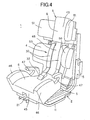
- FIG. 4 is a perspective view showing the outline of the child seat 1.
- the child seat 1 comprises a base unit 2 and a seat unit 3 to be detachably attached to the base unit 2.
- the base unit 2 includes a restraining belt device 4.
- FIG. 5 is a view showing the details of the base unit 2, from which the seat unit 3 is detached.
- the base unit 2 includes a base body 2a.
- the base unit 2 is provided with a support base 11 serving as a supporter on a bottom side, and a back frame 12 serving as a supporter on a back side and extending upward from the rear end of the support base 11.
- the back frame 12 is provided with a pair of main frames 13 erected rearward from both sides of the support base 11, and a connecting portion 14 interposed between the pair of main frames 13.
- a fixing belt guide (hereinafter simply referred to as "a belt guide”) 15 and a lock-off device 16 serving as a restraining device are attached to each of the pair of main frames 13.
- the belt guide 15 is adapted to guide a shoulder belt portion 104 of a seat belt of a vehicle to the back side of the frame 12 when the base unit 2 is fixed to a seat 100 (see FIG. 1) by fitting a tongue 103A, through which the shoulder belt portion 104 is passed, to a buckle 103B.
- the lock-off device 16 is a well-known device for fixing the shoulderbeltportion 104 to the base unit 2 byholding the shoulder belt portion 104 guided to the back side of the frame 12 between a pair of pawls.
- the shoulder belt portion 104 stretched between an anchor, not shown, of the vehicle and a fixing position by the buckle 103B is guided to the back side of the back frame 12 along the belt guide 15 attached to one of the main frames 13 in the base unit 2, to be thus held by the lock-off device 16 disposed in the main frame 13 on the other side. Consequently, a belt length from an anchor of a waist belt portion 105 to the lock-off device 16 is set to a constant value, so that the base unit 2 is fixed to the seat 100.
- the shoulder belt portion 104 is not stretched across the fore side of the base unit 2 so as to avoid any interference of the shoulder belt portion 104 with shoulder belts 30 of the restraining belt device 4.
- the fixing positions of the belt guide 15 and the lock-off device 16 can be changed to the same height position of the main frames 13 on the opposite sides, respectively.
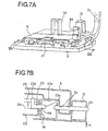
- FIG. 6 shows a state of the position adjusting mechanism 17 in detail, in which the slider 5 is detached from the base unit 2.
- the position adjusting mechanism 17 includes a pair of rails 18 which are disposed in the support base 11 and extend in the longitudinal direction, a lock unit 19 interposed between the pair of rails 18, a pair of rods 20 extending forward of the lock unit 19, and a position adjusting lever 21 secured at the tips of the rods 20.
- the lock unit 19 is provided with a base plate 22 which can move back and forth along and between the rails 18.
- each slider receiver 22a At the upper surfaces of slider receivers 22a at both ends of the base plate 22 is secured the slider 5. Under each slider receiver 22a is disposed a lock pin 23. A tip portion 23a of each lock pin 23 is alternatively inserted into any one of lock holes 18a ... 18a formed at each of the rails 18, so that the slider 5 can be secured at any one of a plurality of positions with intervals in the longitudinal direction.
- Lock pin driving cams 25 are disposed at the upper surface of the base plate 22 via cam bases 24. Each lock pin driving cam 25 is supported movably within a limited range in the longitudinal direction with respect to the cam base 24 by fitting a guide pin 24a of the cambase 24 into a guide groove 25a extending in the longitudinal direction. Moreover, in the lock pin driving cam 25 is formed a pin driving groove 25b inclined slantwise in the longitudinal direction so as to be away forward from the outside of the guide groove 25a. To the pin driving groove 25b is fitted a base portion 23b of the lock pin 23. Additionally, the lock pin driving cam 25 is connected to the rod 20 via a connecting pin 26, and further, is urged rearward by an urging mechanism, not shown. The urging mechanism can hold the lock pin driving cam 25 at a standby position at which the guide pin 24a abuts against the fore end of the guide groove 25a.
- each rail 18 includes a plurality of slider connecting pins 28 projecting outward in a lateral direction.
- the slider connecting pin 28 is fitted into a longitudinal slot 5a formed on the slider 5. Consequently, the slider 5 can be prevented from being slipped off in a vertical direction while allowing the positional adjustment of the slider 5 in the longitudinal direction.
- the fixing portions 31 and 33 project from the upper surface of the slider 5 so as to fix the belts 30 and 32, respectively, at substantially the same height as the seat level of the seat cushion portion 6 disposed in the slider 5.
- each waist belt guide 34 is determined such that the waist belt portion 105 is away forward from the crotch belt fixing portion 33 even if the slider 5 is moved at the fore end within the movable range thereof. Therefore, the waist belt portion 105 is held between the base unit 2 and the seat cushion portion 6 and at a position nearer the fore end than the center in the longitudinal direction of the base unit 2 by the waist belt guides 34.
- Each waist belt guide 34 is configured to hold the band-like waist belt portion 105 in an erecting attitude along the vertical direction, and in other words, to hold the band-like waist belt portion 105 in an attitude in which the width direction of the waist belt portion 105 is oriented substantially in the vertical direction. Since the waist belt portion 105 is inserted into the waist belt guides 34 in the above-described attitude, the base body 2a of the base unit 2 can be firmly held by the waist belt portion 105 against a forward impact acceleration.
- the belt guides 35 for guiding the pair of shoulder belts 30 in the restraining belt device 4 (also see FIG. 14).
- the shoulder belts 30 guided to the back side of the frame 12 via the belt guides 35 are connected to a single adjusting belt 37 via a connecting tool 36.
- the adjusting belt 37 is stretched around a connecting shaft 38 parallel to the strut 7 fixed between the lower ends of the main frames 13, to be thus guided between the support base 11 and the slider 5, and further, is pulled forward of the child seat 1 through a belt adjuster 39 disposed at the fore end of the slider 5.
- the belt adjuster 39 is a well-known belt length adjusting device for allowing the forward pulling operation of the adjusting belt 37 and inhibiting the adjusting belt 37 from being returned rearward unless a predetermined releasing operation is performed.
- a tongue 40 disposed in each shoulder belt 30 is secured to a buckle 41 at the tip of the crotch belt 32, and thereafter, a tip portion 37a of the adjusting belt 37 is drawn forward, so that the length of each shoulder belt 30 stretched between the fixing portion 31 and the belt guide 35 can be adjusted to a desired value.
- bearing portion 42 for rotatably connecting the seat cushion portion 6 is disposed at the rear end of the slider 5.
- the seat cushion portion 6 has a cushion 45, on which a child (a child) sits, and side supports 46 disposed on both sides of the cushion 45.
- Restraining belt guides (hereinafter simply referred to as “belt guides”) 47 for regulating the passing position of the waist belt portion 105 of the vehicle with respect to the seat cushion portion 6 are disposed on both sides at the rear end of the seat cushion portion 6 by cutting out the side supports 46.
- the belt guides 47 are not used in the usage mode of the G1 class, in which the base unit 2 is used. That is to say, the belt guides 47 are used in the usage mode of the G2 class, in which only the seat unit 3 is used, and in the usage mode of the G3 class, in which only the seat cushion portion 6 is used.
- the seat back portion 8 is equipped with a back rest 48 supporting the back of the child and a head rest 49 for supporting the head, and side supports 50 and 51 projecting sideways of the back rest 48 and the head rest 49, respectively.
- the shoulder belts 30 in the restraining belt device 4 are drawn forward of the seat unit 3 through clearances between the side supports 50 and 51.
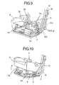
- a recess 55 for avoiding the interference of the waist belt guides 34 and the waist belt portion 105 stretched across the waist belt guides 34 with the seat cushion portion 6 is formed at the reverse side (i.e., the lower surface) of the seat cushion portion 6.
- the size and position of the recess 55 are determined so as to prevent any interfere of the seat cushion portion 6 with the waist belt portion 105 in all the region within a movable range of the slider 5.
- Openings 55a are formed on both sides at the rear end of the recess 55.
- the waist belt portion 105 extending from the waist belt guides 34 toward the anchor and the buckle 103B of the vehicle is drawn outside of the seat cushion portion 6 from the openings 55a.
- one end of each shoulder belt 30 is secured to the fixing portion 31 while the other end is secured to the connecting tool 36, so that the shoulder belt 30 cannot be passed through the seat cushion portion 6 even if a through hole for the shoulder belt 30 is formed on the seat cushion portion 6. Consequently, as for the fixing portions 31 with respect to the shoulder belts 30, grooves 56b opened at the rear end of the seat cushion portion 6 are formed so as to allow the fixing portions 31 to pass through the seat cushion portion 6.
- a cushion rotary shaft 57 is disposed at the rear end of the seat cushion portion 6.
- the cushion rotary shaft 57 extends in the lateral direction of the seat 100, and thus, is rotatably supported on the axis by the bearing portion 42 shown in FIG. 5. Therefore, as shown in FIG. 10, the belt guides 34 can be exposed by lifting up the seat cushion portion 6 around the cushion rotary shaft 57.
- the cushion rotary shaft 57 can be detached from the bearing portion 42. The details of the connecting portion will be described below.
- FIG. 12 shows the connecting portion between the seat cushion portion 6 and the seat back portion 8 in enlargement.
- a pair of holding pawls 58 projecting upward of the slider 5 are disposed at the bearing portion 42 at the rear end of the slider 5.
- Hooks 58a formed at the upper ends of the holding pawls 58 engage with the cushion rotary shaft 57 by fitting the cushion rotary shaft 57 to the holding pawls 58 from the back surface of the base unit 2, thereby inhibiting any of forward and upward movements of the cushion rotary shaft 57.
- the seat cushion portion 6 is connected to the slider 5 in a state liftable around the cushion rotary shaft 57.
- the pair of struts 7 are disposed coaxially with each other at the rear end of the seat cushion portion 6.
- a frame 60 for securing the rigidity of the seat back portion 8 is disposed at the back surface of the seat back portion 8, and further, a pair of arms 61 engageable with the struts 7 are disposed at the lower end of the frame 60.
- the arm 61 is provided with a semi-circular portion 61a fitted around substantially the fore half circumference of the strut 7.
- the arm 61 is inserted forward of the strut 7, and thus, the semi-circular portion 61a engages with the strut 7 , so that the seat back portion 8 can be rotatably connected on the strut 7 with respect to the seat cushion portion 6.
- the arm 61 is rotated on the strut 7, thereby changing the reclining angle of the seat back portion 8.
- the strut 7 is away from the arm 61, and therefore, the strut 7 cannot interfere with the lifting-up operation of the seat cushion portion 6.
- FIG. 14 shows the details of the connection portion 14 disposed on the back frame 12 in order to connect the seat back portion 8 to the base unit 2.
- the connection portion 14 includes a pair of cross bars 65 stretched between the main frames 13, a guide rod 66 extending vertically across the cross bars 65, and a vertically movable slider 67 under the guidance of the guide rod 66 and the main frames 13.
- a center supporter 68 projecting forward.
- pin inserting holes 68a (only either one of which is shown in FIG. 14).
- Auxiliary supporters 69 are formed besides the center supporter 68.
- a receiving groove 69a is formed at each of the auxiliary supporters 69.
- a guide pin 70 projecting outward in the lateral direction is formed at the upper portion of each of the auxiliary supporters 69.
- slide guides 71 sliding along the main frames 13 are disposed at the lower portion of the slider 67.
- the above-described belt guides 35 are disposed inward of the slide guides 71.
- the belt guides 35 are vertically moved integrally with the supporters 68 and 69. Consequently, it is possible to position all the time the belt guides 35 in a clearance formed between the side supports 50 and 51 in the seat back portion 8 connected to the slider 67, so as to prevent any change of the drawing position of the shoulder belts 30 with respect to the seat unit 3.
- each slide guide 71 is selectively fitted into any one of the plurality of pin inserting holes 13a formed at the main frame 13. In this manner, the slider 67 can be selectively positioned at any one of a plurality of positions in the vertical direction.
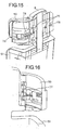
- connecting pins 75 to be fitted into the pin inserting holes 68a formed on the slider 67 are secured so as to be slidable in the lateral direction.
- the seat back portion 8 is connected to the back frame 12 via the slider 67 so as to be rotatable about connecting pins 75 by inserting the connecting pins 75 into the pin inserting holes 68a (see FIG. 14) formed on the sliders 67 of the connecting portion 14.
- the ends of the connectingpins 75 are connectedto operating levers 76, respectively.
- the operating lever 76 is attached to the side support 50 in a manner slidable in the lateral direction. Furthermore, as shown in FIG. 16, the operating lever 76 is pulled inward of the side support 50 by a tension coil spring 77 serving as an urging device incorporated in the side support 50.
- a tension coil spring 77 serving as an urging device incorporated in the side support 50.
- the connecting pin 75 can be fitted into or drawn from the pin inserting hole 68a formed at the slider 67.
- the connecting pin 75 is inserted into a pin guide 78 whose periphery is rounded into an arcuate shape.
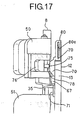
- FIG. 17 shows a state where the seat back portion 8 is connected to the back frame 12 via the connecting portion 14.
- the pin guide 78 with respect to the connecting pin 75 is fitted into the receiving groove 69a (see FIG. 14) of the auxiliary supporter 69 disposed in the slider 67. Consequently, a rearward load to be exerted on the seat back portion 8 can be supported by the supporters 68 and 69.
- a guide 80 is disposed at the upper end of the main frame 13, and further, a slot 80a extending in parallel in the lengthwise direction of the main frame 13 is formed at the guide 80. The movement direction of the slider 67 is restricted to the lengthwise direction of the main frame 13 by inserting the guide pin 70 of the slider 67 into the slot 80a.
- the seat unit 3 can be attached to the base unit 2 by putting the seat cushion portion 6 onto the slider 5, engaging the cushion rotary shaft 57 with the bearing portion 42, engaging the arm 61 of the seat back portion 8 with the strut 7, and inserting the connecting pin 75 of the seat back portion 8 into the pin inserting hole 68a provided on the slider 67 on the back frame 12.
- the child is restrained in the seat unit 3 by using the restraining belt device 4, thereby achieving the child seat of the G1 class.
- the inclination of the seat back portion 8 is varied by adjusting the position of the slider 5 in the longitudinal direction by the operation of the position adjusting lever 21, thereby achieving a desired reclining attitude.
- an expansion/contraction mechanism is incorporated in the seat back portion 8, the change can be absorbed by the expansion/contraction mechanism incorporated in the seat back portion 8 even if the distance between the strut 7 and the connecting pin 75 is changed by the lengthwise movement of the slider 5. Therefore, itisunnecessary to adjust the position of the slider 67 in the vertical direction.
- the height of the headrest 49 can be adjusted according to the build of the child by vertically moving the slider 67.
- the seat unit 3 can be detached from the base unit 2 by lifting up the seat cushion portion 6, detaching the cushion rotary shaft 57 from the bearing portion 42, and drawing the connecting pin 75 in the seat back portion 8 from the pin inserting hole 68a, thereby achieving the child seats of the G2 and G3 classes for restraining the child by using only the seat unit 3 or the seat cushion portion 6 and the seat belt of the vehicle.
- the present invention is not limited to the above-described embodiment, and therefore, it may be carried out in various modes.
- the number of belt guides 34 on the base is not limited to two, but it may be appropriately varied if it is necessary to hold the waist belt portion 105.
- the belt guide 34 may be continuously disposed over the entire width of the slider 5.
- the present invention is applicable irrespective of the existence of the reclining mechanism by using the slider 5.
- the seat cushion portion and the seat back portion may be molded integrally with each other in the configuration of the seat unit.
- the seat cushion portion 6 and the seat back portion 8 in the seat unit 3 can be detached from each other, thereby coping with the child seat of the G3 class, in which only the seat cushion portion 6 is used.
- the child seat according to the present invention need not always cope with the plurality of classes.
- the present invention is applicable to a child seat which copes with only a single class as long as a child seat including a base unit and a seat unit is of a type in which the base unit is restrained to a seat by a waist belt portion of a seat belt.
- the base unit may be configured such that the seat unit is fixed only onto the seat cushion 101.
- the seat back in the seat unit may be supported by the lower portion of the seat back, and at the same time, the upper end of the seat back may be supported by the seat back of the seat.
- the base unit should be configured so as to include a portion to be placed on the seat cushion 101 and a portion to be pressed against the seat back 102.
- the waist belt guide in the base unit is disposed nearer the fore end, the waist belt portion extending toward the waist belt guide from the buckle of the seat belt or the belt fixing position on a floor in the vehicle is reduced in inclination angle with respect to the horizontal direction in comparison with the case where the waist belt portion is hooked at the rear end of the base unit. Consequently, it is possible to more securely inhibit the movement of the base unit forward of the seat by more firmly restraining the base unit in the longitudinal direction by the waist belt portion. Furthermore, the waist belt is concealed by inserting the waist belt portion between the seat cushion portion and the base unit, thereby producing an advantage of prevention of the movement of the waist belt portion by an external factor.
Landscapes
- Engineering & Computer Science (AREA)
- Health & Medical Sciences (AREA)
- Child & Adolescent Psychology (AREA)
- General Health & Medical Sciences (AREA)
- Aviation & Aerospace Engineering (AREA)
- Transportation (AREA)
- Mechanical Engineering (AREA)
- Seats For Vehicles (AREA)
- Automotive Seat Belt Assembly (AREA)
Abstract
Description
Claims (8)
- A child seat characterized by comprising:a base unit (2) fixed onto a seat (100) of a vehicle by using a seat belt (104,105) of the vehicle; anda seat unit (3) including a seat cushion portion (6) and a seat back portion (8) and fixable onto the base unit in a forward attitude with respect to the seat, whereina waist belt portion (105) of the seat belt can be inserted in a lateral direction of the seat between the base unit and the seat cushion portion placed on the base unit, and a waist belt guide (34) for inhibiting the movement of the base unit forward of the seat by hooking the waist belt portion inserted between the base unit and the seat cushion portion is provided in the base unit so as to hold the waist belt portion at a position nearer a fore end than the center in a longitudinal direction of the base unit.
- The child seat according to claim 1, wherein the waist belt guide is provided such that the waist belt portion is hooked in a state oriented substantially vertically in a width direction.
- The child seat according to claim 1 or 2, wherein the base unit is provided with a base body (2a) fixed to the seat of the vehicle and a slider (5) disposed in a positionally adjustable manner in the longitudinal direction with respect to the base body, the seat cushion portion is fixed to the slider and the waist belt guide is fixed to the base body.
- The child seat according to claim 3, wherein the base unit is provided with a restraining belt device (4) which comprises a pair of shoulder belts (30) for restraining a child sitting on the seat cushion portion and a crotch belt (32) connected to the shoulder belts, one end of each of the shoulder belts and the crotch belt is fixed to a belt fixing portion of the slider, and the waist belt guide is provided such that the waist belt portion passes between the seat cushion portion and the base unit forward of a position of the belt fixing portion with respect to the crotch belt when the slider is positioned at a fore end within a movable range of the slider.
- The child seat according to claim 3 or 4, wherein a recess (55), through which the waist belt portion passes, is formed on the lower side of the seat cushion portion so as to prevent any interfere of the seat cushion portion with the waist belt portion over the entire region within the movable range of the slider.
- The child seat according to any one of claims 1 to 5, wherein the seat cushion portion is movably disposed with respect to the base unit so as to allow the waist belt guide to be exposed.
- The child seat according to claim 6, wherein the waist belt guide is exposed by lifting up the seat cushion portion around a cushion rotary shaft (57) extending in the lateral direction of the seat disposed at the end in the longitudinal direction of the seat cushion portion.
- The child seat according to any one of claims 1 to 7, wherein a back supporter (12) abutting against a seat back (102) of the seat of the vehicle so as to support the seat back portion from the back side thereof is disposed in the base unit, and the back supporter is provided with a lock-off device (16) for restraining a shoulder belt portion of the seat belt of the vehicle.
Applications Claiming Priority (2)
| Application Number | Priority Date | Filing Date | Title |
|---|---|---|---|
| JP2003187426A JP4234511B2 (en) | 2003-06-30 | 2003-06-30 | child seat |
| JP2003187426 | 2003-06-30 |
Publications (2)
| Publication Number | Publication Date |
|---|---|
| EP1493614A2 true EP1493614A2 (en) | 2005-01-05 |
| EP1493614A3 EP1493614A3 (en) | 2008-10-08 |
Family
ID=33432256
Family Applications (1)
| Application Number | Title | Priority Date | Filing Date |
|---|---|---|---|
| EP04015379A Withdrawn EP1493614A3 (en) | 2003-06-30 | 2004-06-30 | Child seat |
Country Status (6)
| Country | Link |
|---|---|
| US (1) | US7237840B2 (en) |
| EP (1) | EP1493614A3 (en) |
| JP (1) | JP4234511B2 (en) |
| KR (1) | KR20050002595A (en) |
| CN (1) | CN100493954C (en) |
| TW (1) | TW200516020A (en) |
Cited By (3)
| Publication number | Priority date | Publication date | Assignee | Title |
|---|---|---|---|---|
| ITMI20081654A1 (en) * | 2008-09-17 | 2010-03-17 | Artsana Spa | METHOD TO REALIZE A BASIS OF SUPPORT FOR A CAR SEAT FOR CHILDREN, BASE AND SEAT SO OBTAINED |
| EP2308716A4 (en) * | 2008-07-02 | 2013-06-26 | Combi Corp | CHILD SEAT |
| EP4105072A1 (en) * | 2021-06-15 | 2022-12-21 | BRITAX RÖMER Kindersicherheit GmbH | Child safety seat |
Families Citing this family (9)
| Publication number | Priority date | Publication date | Assignee | Title |
|---|---|---|---|---|
| NL1029196C2 (en) * | 2005-06-06 | 2006-12-07 | Maxi Miliaan Bv | Undercarriage as well as assembly provided with such an undercarriage. |
| US7887128B2 (en) * | 2008-05-21 | 2011-02-15 | Cosco Management, Inc. | Child restraint including adjustable base |
| JP5312858B2 (en) * | 2008-07-02 | 2013-10-09 | コンビ株式会社 | child seat |
| US20100244543A1 (en) * | 2009-03-26 | 2010-09-30 | Graco Children's Products Inc. | Harness Buckle and Chest Clip Release |
| USD641180S1 (en) | 2009-09-11 | 2011-07-12 | Helen Of Troy Limited | Highchair |
| US8240765B2 (en) * | 2009-09-11 | 2012-08-14 | Helen Of Troy Limited | Child chair |
| US8998318B2 (en) * | 2011-08-18 | 2015-04-07 | Cosco Management, Inc. | Child restraint with tiltable juvenile seat |
| CN203543727U (en) * | 2012-11-02 | 2014-04-16 | 明门香港股份有限公司 | Safety seat with adjustable inclination angle |
| CN106042989A (en) * | 2016-06-15 | 2016-10-26 | 朱森 | Safety car seat |
Family Cites Families (12)
| Publication number | Priority date | Publication date | Assignee | Title |
|---|---|---|---|---|
| GB9405860D0 (en) * | 1994-03-24 | 1994-05-11 | Britax Excelsior | Infant safety seat |
| NL1001896C2 (en) * | 1995-12-13 | 1997-06-17 | Dremefa Mach Metaal | Child safety seat. |
| US5695243A (en) * | 1996-01-31 | 1997-12-09 | Indiana Mills And Manufacturing, Inc. | Child seat mount with anti-twist web mechanism |
| US6220662B1 (en) * | 1996-04-23 | 2001-04-24 | Dme Corporation | Aircraft seat child restraint device |
| SE512317C2 (en) * | 1998-06-26 | 2000-02-28 | Torgersen Hans & Soenn | Car seat |
| ES1043376Y (en) * | 1998-11-10 | 2000-05-01 | Jane Sa | BODY-CRADLE. |
| GB9919322D0 (en) * | 1999-08-17 | 1999-10-20 | Britax Roemer Kindersicherheit Gmbh | Child safety seat |
| US6505887B2 (en) * | 1999-11-09 | 2003-01-14 | Lewis E. Hampton | Infant's restraining seat |
| US6554358B2 (en) * | 2000-09-22 | 2003-04-29 | Cosco Management, Inc. | Infant vehicle seat with tiltable base |
| US6672663B2 (en) * | 2000-09-22 | 2004-01-06 | Cosco Management, Inc. | Retainer system for juvenile vehicle seat |
| GB0103983D0 (en) * | 2001-02-17 | 2001-04-04 | Britax Roemer Kindersicherheit Gmbh | Child safety seat |
| NO316877B1 (en) * | 2001-07-18 | 2004-06-07 | Hts Hans Torgersen & Sonn As | Child restraint system |
-
2003
- 2003-06-30 JP JP2003187426A patent/JP4234511B2/en not_active Expired - Fee Related
-
2004
- 2004-06-29 KR KR1020040049210A patent/KR20050002595A/en not_active Withdrawn
- 2004-06-29 US US10/878,934 patent/US7237840B2/en not_active Expired - Fee Related
- 2004-06-29 CN CNB2004100619713A patent/CN100493954C/en not_active Expired - Fee Related
- 2004-06-30 EP EP04015379A patent/EP1493614A3/en not_active Withdrawn
- 2004-06-30 TW TW093119625A patent/TW200516020A/en unknown
Cited By (5)
| Publication number | Priority date | Publication date | Assignee | Title |
|---|---|---|---|---|
| EP2308716A4 (en) * | 2008-07-02 | 2013-06-26 | Combi Corp | CHILD SEAT |
| ITMI20081654A1 (en) * | 2008-09-17 | 2010-03-17 | Artsana Spa | METHOD TO REALIZE A BASIS OF SUPPORT FOR A CAR SEAT FOR CHILDREN, BASE AND SEAT SO OBTAINED |
| EP2165877A1 (en) | 2008-09-17 | 2010-03-24 | ARTSANA S.p.A. | Method of assembly of a supporting base for a child's car seat, base and child's car seat thus obtained |
| US8047608B2 (en) | 2008-09-17 | 2011-11-01 | Artsana S.P.A. | Method for implementing a supporting base of a car seat for children, base and car seat thus obtained |
| EP4105072A1 (en) * | 2021-06-15 | 2022-12-21 | BRITAX RÖMER Kindersicherheit GmbH | Child safety seat |
Also Published As
| Publication number | Publication date |
|---|---|
| US20040262967A1 (en) | 2004-12-30 |
| JP2005022447A (en) | 2005-01-27 |
| US7237840B2 (en) | 2007-07-03 |
| TW200516020A (en) | 2005-05-16 |
| KR20050002595A (en) | 2005-01-07 |
| CN1576094A (en) | 2005-02-09 |
| CN100493954C (en) | 2009-06-03 |
| JP4234511B2 (en) | 2009-03-04 |
| EP1493614A3 (en) | 2008-10-08 |
Similar Documents
| Publication | Publication Date | Title |
|---|---|---|
| US7086695B2 (en) | Child seat | |
| CA2126123C (en) | Child safety seat for automobile | |
| US10780800B2 (en) | Child safety seat with anti-rotation device | |
| JP3766821B2 (en) | Childcare equipment | |
| US6428099B1 (en) | Child vehicle seat with adjustable and removable base | |
| US7237840B2 (en) | Child seat | |
| CN101954874B (en) | Seat device for vehicle | |
| GB2429641A (en) | Child safety seat with belt buckle positioning means | |
| CN103153696A (en) | Child seat | |
| JPH07251661A (en) | Car seat with integrated child seat | |
| JP2022106688A (en) | Shoulder belt assembly and baby carriage | |
| US20250178492A1 (en) | Seat cushion structure and child safety seat | |
| JP6676320B2 (en) | child seat | |
| JP4520734B2 (en) | child seat | |
| JP2025502335A (en) | Child Carriage Device with Belt System, Particularly a Stroller and/or a Child Seat | |
| JP4223875B2 (en) | child seat | |
| WO2005053998A1 (en) | Child seat | |
| JPH0642464U (en) | Child seat | |
| JPH07165012A (en) | Car seat | |
| KR101847442B1 (en) | Assist device for safety bell of vehicle | |
| CN112297969A (en) | Child care implement | |
| JP4520733B2 (en) | child seat | |
| CN112297970B (en) | Child care implement for children | |
| JP2002249020A (en) | Three-point belt mount seat | |
| JP2003080988A (en) | Seat belt mounting structure |
Legal Events
| Date | Code | Title | Description |
|---|---|---|---|
| PUAI | Public reference made under article 153(3) epc to a published international application that has entered the european phase |
Free format text: ORIGINAL CODE: 0009012 |
|
| AK | Designated contracting states |
Kind code of ref document: A2 Designated state(s): AT BE BG CH CY CZ DE DK EE ES FI FR GB GR HU IE IT LI LU MC NL PL PT RO SE SI SK TR |
|
| AX | Request for extension of the european patent |
Extension state: AL HR LT LV MK |
|
| PUAL | Search report despatched |
Free format text: ORIGINAL CODE: 0009013 |
|
| AK | Designated contracting states |
Kind code of ref document: A3 Designated state(s): AT BE BG CH CY CZ DE DK EE ES FI FR GB GR HU IE IT LI LU MC NL PL PT RO SE SI SK TR |
|
| AX | Request for extension of the european patent |
Extension state: AL HR LT LV MK |
|
| STAA | Information on the status of an ep patent application or granted ep patent |
Free format text: STATUS: THE APPLICATION IS DEEMED TO BE WITHDRAWN |
|
| AKX | Designation fees paid | ||
| 18D | Application deemed to be withdrawn |
Effective date: 20090106 |
|
| REG | Reference to a national code |
Ref country code: DE Ref legal event code: 8566 |