EP1493201B1 - Battery separator with mud rest protectors - Google Patents
Battery separator with mud rest protectors Download PDFInfo
- Publication number
- EP1493201B1 EP1493201B1 EP03716893A EP03716893A EP1493201B1 EP 1493201 B1 EP1493201 B1 EP 1493201B1 EP 03716893 A EP03716893 A EP 03716893A EP 03716893 A EP03716893 A EP 03716893A EP 1493201 B1 EP1493201 B1 EP 1493201B1
- Authority
- EP
- European Patent Office
- Prior art keywords
- ribs
- submini
- battery separator
- backweb
- planar surface
- Prior art date
- Legal status (The legal status is an assumption and is not a legal conclusion. Google has not performed a legal analysis and makes no representation as to the accuracy of the status listed.)
- Expired - Lifetime
Links
- 230000001012 protector Effects 0.000 title 1
- 239000002253 acid Substances 0.000 claims abstract description 20
- 239000003792 electrolyte Substances 0.000 claims abstract description 6
- 230000015572 biosynthetic process Effects 0.000 claims description 7
- 238000000034 method Methods 0.000 claims description 4
- 239000002244 precipitate Substances 0.000 claims 2
- 208000032953 Device battery issue Diseases 0.000 abstract description 4
- 230000006835 compression Effects 0.000 abstract description 4
- 238000007906 compression Methods 0.000 abstract description 4
- 239000000463 material Substances 0.000 description 11
- 239000004698 Polyethylene Substances 0.000 description 7
- -1 polyethylene Polymers 0.000 description 7
- 229920000573 polyethylene Polymers 0.000 description 7
- 238000004519 manufacturing process Methods 0.000 description 6
- PPBRXRYQALVLMV-UHFFFAOYSA-N Styrene Chemical compound C=CC1=CC=CC=C1 PPBRXRYQALVLMV-UHFFFAOYSA-N 0.000 description 4
- 238000005452 bending Methods 0.000 description 3
- 230000007423 decrease Effects 0.000 description 3
- 238000010586 diagram Methods 0.000 description 3
- 229920001187 thermosetting polymer Polymers 0.000 description 3
- KAKZBPTYRLMSJV-UHFFFAOYSA-N Butadiene Chemical compound C=CC=C KAKZBPTYRLMSJV-UHFFFAOYSA-N 0.000 description 2
- RRHGJUQNOFWUDK-UHFFFAOYSA-N Isoprene Chemical compound CC(=C)C=C RRHGJUQNOFWUDK-UHFFFAOYSA-N 0.000 description 2
- QAOWNCQODCNURD-UHFFFAOYSA-N Sulfuric acid Chemical compound OS(O)(=O)=O QAOWNCQODCNURD-UHFFFAOYSA-N 0.000 description 2
- 230000003247 decreasing effect Effects 0.000 description 2
- 230000003111 delayed effect Effects 0.000 description 2
- 239000002003 electrode paste Substances 0.000 description 2
- 238000000605 extraction Methods 0.000 description 2
- 239000004615 ingredient Substances 0.000 description 2
- 230000002028 premature Effects 0.000 description 2
- 229920001169 thermoplastic Polymers 0.000 description 2
- YVLJEXBGMVDKBR-UHFFFAOYSA-N 1,10-dichloro-7-methyldec-1-ene Chemical compound ClCCCC(C)CCCCC=CCl YVLJEXBGMVDKBR-UHFFFAOYSA-N 0.000 description 1
- VYPSYNLAJGMNEJ-UHFFFAOYSA-N Silicium dioxide Chemical compound O=[Si]=O VYPSYNLAJGMNEJ-UHFFFAOYSA-N 0.000 description 1
- 239000004699 Ultra-high molecular weight polyethylene Substances 0.000 description 1
- 238000009825 accumulation Methods 0.000 description 1
- 239000003963 antioxidant agent Substances 0.000 description 1
- 230000003078 antioxidant effect Effects 0.000 description 1
- 239000011324 bead Substances 0.000 description 1
- 239000006229 carbon black Substances 0.000 description 1
- 238000010276 construction Methods 0.000 description 1
- 229920001577 copolymer Polymers 0.000 description 1
- 150000001993 dienes Chemical class 0.000 description 1
- 238000001035 drying Methods 0.000 description 1
- 230000008030 elimination Effects 0.000 description 1
- 238000003379 elimination reaction Methods 0.000 description 1
- 238000004049 embossing Methods 0.000 description 1
- 238000005516 engineering process Methods 0.000 description 1
- HQQADJVZYDDRJT-UHFFFAOYSA-N ethene;prop-1-ene Chemical group C=C.CC=C HQQADJVZYDDRJT-UHFFFAOYSA-N 0.000 description 1
- 239000000945 filler Substances 0.000 description 1
- YADSGOSSYOOKMP-UHFFFAOYSA-N lead dioxide Inorganic materials O=[Pb]=O YADSGOSSYOOKMP-UHFFFAOYSA-N 0.000 description 1
- HTUMBQDCCIXGCV-UHFFFAOYSA-N lead oxide Chemical compound [O-2].[Pb+2] HTUMBQDCCIXGCV-UHFFFAOYSA-N 0.000 description 1
- PIJPYDMVFNTHIP-UHFFFAOYSA-L lead sulfate Chemical compound [PbH4+2].[O-]S([O-])(=O)=O PIJPYDMVFNTHIP-UHFFFAOYSA-L 0.000 description 1
- 239000000314 lubricant Substances 0.000 description 1
- 239000002184 metal Substances 0.000 description 1
- 239000000203 mixture Substances 0.000 description 1
- 229920003023 plastic Polymers 0.000 description 1
- 239000004033 plastic Substances 0.000 description 1
- 239000004014 plasticizer Substances 0.000 description 1
- 229920000642 polymer Polymers 0.000 description 1
- 235000013824 polyphenols Nutrition 0.000 description 1
- 239000011148 porous material Substances 0.000 description 1
- 238000007789 sealing Methods 0.000 description 1
- 239000002904 solvent Substances 0.000 description 1
- 239000000126 substance Substances 0.000 description 1
- 239000004634 thermosetting polymer Substances 0.000 description 1
- 239000004416 thermosoftening plastic Substances 0.000 description 1
- 229920000785 ultra high molecular weight polyethylene Polymers 0.000 description 1
- 238000004804 winding Methods 0.000 description 1
Images



Classifications
-
- H—ELECTRICITY
- H01—ELECTRIC ELEMENTS
- H01M—PROCESSES OR MEANS, e.g. BATTERIES, FOR THE DIRECT CONVERSION OF CHEMICAL ENERGY INTO ELECTRICAL ENERGY
- H01M50/00—Constructional details or processes of manufacture of the non-active parts of electrochemical cells other than fuel cells, e.g. hybrid cells
- H01M50/40—Separators; Membranes; Diaphragms; Spacing elements inside cells
- H01M50/463—Separators, membranes or diaphragms characterised by their shape
-
- H—ELECTRICITY
- H01—ELECTRIC ELEMENTS
- H01M—PROCESSES OR MEANS, e.g. BATTERIES, FOR THE DIRECT CONVERSION OF CHEMICAL ENERGY INTO ELECTRICAL ENERGY
- H01M10/00—Secondary cells; Manufacture thereof
- H01M10/06—Lead-acid accumulators
-
- Y—GENERAL TAGGING OF NEW TECHNOLOGICAL DEVELOPMENTS; GENERAL TAGGING OF CROSS-SECTIONAL TECHNOLOGIES SPANNING OVER SEVERAL SECTIONS OF THE IPC; TECHNICAL SUBJECTS COVERED BY FORMER USPC CROSS-REFERENCE ART COLLECTIONS [XRACs] AND DIGESTS
- Y02—TECHNOLOGIES OR APPLICATIONS FOR MITIGATION OR ADAPTATION AGAINST CLIMATE CHANGE
- Y02E—REDUCTION OF GREENHOUSE GAS [GHG] EMISSIONS, RELATED TO ENERGY GENERATION, TRANSMISSION OR DISTRIBUTION
- Y02E60/00—Enabling technologies; Technologies with a potential or indirect contribution to GHG emissions mitigation
- Y02E60/10—Energy storage using batteries
Definitions
- This invention relates to a battery separator for use in a flooded cell-type lead acid battery and to a method for making such a separator.
- the positive and negative electrodes are separated by a battery separator.
- Such separators are formed of materials that are sufficiently porous to permit the electrolyte of the battery to reside in the pores of the separator material, thereby permitting ionic current flow between adjacent positive and negative plates, but not so porous to allow physical contact between the electrodes or "treeing" of lead between adjacent electrodes.
- the battery separator currently used by most flooded cell-type lead acid battery manufacturers includes microporous polyethylene.
- This type of separator is composed of an ultrahigh molecular weight polyethylene, a filler (typically amorphous silica), a plasticizer (typically a processing oil), and certain minor ingredients such as an antioxidant, a lubricant, and carbon black.
- Microporous polyethylene separator material is commercially manufactured by passing the ingredients through a heated extruder, passing the extrudate generated by the extruder through a die and into a nip formed by two heated calender rolls to form a continuous web.
- the continuous web is processed by extracting a substantial amount of the processing oil from the web using a solvent, drying the extracted web, slitting the web into lanes of predetermined width, and winding the lanes into rolls.
- Figs. 1 and 2 are top views of, respectively, an empty cell compartment 10 and an open-ended enveloped electrode 12 placed within cell compartment 10. While cell compartment 10 can be made of any material known in the art, the cell compartment shown in Figs. 1 and 2 is made of polyethylene plastic.
- separators are manufactured to have multiple "major" ribs extending from at least one planar face of the backweb of the separator.
- the major ribs function to provide proper electrode spacing and to provide a space in which free electrolyte can reside.
- the major ribs are typically formed parallel to the longitudinal edges of the backweb and generally have a height above the backweb that is greater than the thickness of the backweb.
- the ribs may be formed in one of several ways: (1) the ribs can be formed integrally with the backweb; (2) the ribs can be subsequently applied to the backweb as a bead of the same material as or different material from that of the backweb; or (3) the ribs can be formed by embossing the backweb.
- the major ribs have a greater volume than a portion of the backweb occupying the same planar surface area, more processing oil remains in the major ribs during the extraction step than that which remains in the backweb, resulting in undesirably increased electrical resistance.
- separators having major ribs are more expensive to manufacture in light of the additional separator material that is incorporated into the major ribs.
- Separators also help to hold the electrochemically active paste on the wire grids of the electrodes during battery operation. Although separators serve to limit the amount of electrode paste that falls to the bottom of the cell compartment, operational vibrations of certain batteries (car batteries, for example) are so violent that a significant amount of paste naturally falls off the electrodes and pools on the bottom of the cell compartment. While on the bottom of the cell compartment, the electrode paste reacts with other chemicals that rest there, forming what is referred to as "mud.” Mud typically includes residual sulfuric acid, lead sulfate, PbO, and PbO 2 . The accumulation of mud in the bottom of the cell compartment causes battery failure because the lower portion of each electrode makes contact with the accumulated mud, causing the battery to short-circuit.
- mud rests 14 are U-shaped planar members that extend along and upward from the bottom surface 16 of cell compartment 10, thereby separating from the enveloped electrodes the paste residue that falls from the electrodes and pools on the bottom of cell compartment 10. Mud rests 14 typically extend across the battery from wall to wall, although they may be staggered.
- the mud rests prevent the enveloped electrodes from contacting the mud
- the mud rests are typically of a thickness that allows a single mud rest to lie adjacent to the separator backweb between two adjacent submini-ribs.
- the sharp-cornered mud rests rub against the backweb, creating one or more wear areas that ultimately develop into one or more holes in the separator. Over time, these holes cause the battery to short-circuit.
- the object of the invention is to provide a single, economically efficient and operational flooded cell-type lead acid battery in which battery separators with major and submini-ribs prevent or at least delay the formation of wear areas.
- Another object of the invention is to provide a battery separator for use in an economically efficient and operational lead acid battery and respectively a method for constructing an improved battery separator with submini-ribs for use in an economically efficient and operational lead acid battery.
- the technical problem is solved by a lead acid battery with battery separators according to claim 1, a battery separator according to claim 2 and respectively by a method of constructing a battery separator according to claim 21.
- Another aspect of the present invention is to provide an economically efficient separator having (1) major ribs that provide the proper electrode spacing and a space in which free electrolyte can reside and (2) submini-ribs that reduce the manufacturing costs and the electrical resistance of the separator.
- the separator envelops an electrode and is placed into a cell compartment having mud rests that separate the mud from the enveloped electrode so that the incidence of battery failure is minimized.
- the separator of the present invention includes multiple major and submini-ribs that are pattered such that the predominant web structure that rests against the mud rests at the bottom of the cell compartment are the submini-ribs.
- a battery separator 20 of this invention is comprised of a backweb 22 having a first (upper) planar surface 24, a second (lower) planar surface 26, and respective first and second longitudinal edges 28 and 30 (shown in Fig. 6 ) that are parallel to each other.
- the width of the separator of this invention can be any width desired by battery manufacturers. Typical separator widths are between about 115 mm and about 170 mm.
- the thickness of backweb 22 is typically between about 0.05 mm and about 0.20 mm.
- Major ribs 34a - 34c project from upper planar surface 24 of separator 20.
- Major ribs 34 are disposed in the longitudinal direction of separator 20, are positioned substantially parallel to longitudinal edges 28 and 30, and may have any cross-sectional configuration used in the art.
- Major ribs 34 are typically parallel to one another and to edges 28 and 30, but may be inclined at an angle to edges 28 and 30 (i.e., be diagonally disposed), or may be sinusoidal rather than straight.
- Major ribs 34 project above upper planar surface 24 of baclcweb 22 a height of between about 0.50 mm and about 1.5 mm.
- the number of major ribs provided on a separator sheet varies according to the battery specifications; however, a preferred embodiment includes eight major ribs for each separator sheet.
- the distance between adjacent major ribs 34 is typically between about 10 mm and about 25 mm.
- Submini-ribs 40 are longitudinally disposed along the length of separator 20, and adjacent ones of them are substantially evenly spaced from each other.
- Submini-ribs 40 preferably extend from only one planar face of separator 20 and are preferably disposed substantially parallel to each other and to edges 28 and 30.
- submini-ribs 40 may have other configurations, such as inclined at an angle to edges 28 and 30 or being sinusoidal rather than straight.
- Submini-ribs 40 preferably have rounded apexes, as shown in Fig. 4 .
- the height of submini-ribs 40 above upper planar surface 24 is selected in accordance with the desired height of major ribs 34 and the desired compression resistance, but is preferably between about 0.025 mm and about 0.125 mm, and is most preferably about 0.08 mm.
- submini-ribs 40 there are preferably 20 submini-ribs 40 provided between adjacent major ribs 34.
- the distance between adjacent submini-ribs is preferably between about 0.75 mm and about 0.96 mm, most preferably about 0.825 mm.
- Adjacent submini-ribs 40 are preferably uniformly spaced apart.
- Major ribs 34 and submini-ribs 40 are patterned such that only submini-ribs 40 of the separator-enveloped electrodes rest against mud rests 14 at the bottom of cell compartment 10.
- the backweb of the separator rubbed against mud rests 14, which eventually resulted in the formation of a wear area, and over time, holes in the separator.
- only submini-ribs 40 which are thicker than backweb 22, contact mud rests 14. Thus the formation of a wear area, and eventually one or more holes, in separator 20 is significantly delayed.
- Shoulder regions 50 are located between the last major ribs 34 and edges 28 and 30 of the separator, as shown in Fig. 5 .
- Shoulder region 50 is the area in which separator 20 is sealed to form an enveloped electrode.
- the electrodes positioned adjacent to the separator sheets often have sharp metal protrusions called "bent wires" that can abrade and puncture the adjacent separator, thereby causing a short circuit and premature failure of the battery.
- shoulder regions 50 are constructed to be more durable and puncture-resistant than the other portions of separator 20. Consequently, most shoulder regions include multiple mini-ribs 52.
- an unribbed region 56 having a length between about 3.0 mm and 3.5 mm is preferably provided between mini-ribs 52 and major rib 34.
- mini-ribs 52 have flattened upper surfaces, and the maximum preferred spacing between adjacent mini-ribs 52 is about 0.563 mm.
- Mini-ribs 52 are preferably longitudinally disposed, and substantially evenly spaced along the length of separator 20.
- Mini-ribs 52 are preferably disposed substantially parallel to one another and to longitudinal side edges 28 and 30, but may have other configurations, such as inclined at an angle to longitudinal side edges 28 and 30, or being sinusoidal rather than straight. Although they preferably extend from only one of planar surfaces 24 and 26, mini-ribs 52 may extend from both planar surfaces in shoulders region 50, and may be staggered so that a mini-rib on one planar surface is located between two mini-ribs located on the other planar surface. While mini-ribs 52 are not necessary to the present invention, their presence greatly increases the strength and durability of the shoulder region and thereby decreases the incidence of short-circuiting and premature battery failure.
- a first exemplary microporous polyethylene battery separator of the present invention was made having the following characteristics, all dimensions being in millimeters: Separator width: 162.56 Backweb thickness: 0.15 Major ribs: Number: 8 Height: 0.61 Width: 0.38 Spacing: 18.14 Submini-Ribs: Number: 20 (between adjacent major ribs) Height: 0.08 Width: 0.25 Spacing: 0.86 Mini-Ribs: Number: 18 (on each shoulder) Height: 0.10 Width: Width from Slope to Slope: 0.29 Width of the Flat Apex: 0.25 Spacing: 0.17 Shoulder Length: 17.78 (from last major rib to end of sheet)
- a second exemplary microporous polyethylene battery separator of the present invention was made having the following characteristics, all dimensions being in millimeters: Separator width: 162.56 Backweb thickness: 0.15 Major ribs: Number: 8 Height: 0.48 Width: 0.38 Spacing: 18.14 Submini-Ribs: Number: 20 (between adjacent major ribs) Height: 0.08 Width: 0.15 Spacing: 0.86 Mini-Ribs: Number: 18 (on each shoulder) Height: 0.10 Width: Width from Slope to Slope: 0.29 Width of the Flat Apex: 0.25 Spacing: 0.17 Shoulder Length: 17.78 (from last major rib to end of sheet)
- a third exemplary microporous polyethylene battery separator of the present invention was made having the following characteristics, all dimensions being in millimeters: Separator width: 162.56 Backweb thickness: 0.15 Major ribs: Number: 8 Height: 0.73 Width: 0.38 Spacing: 18.14 Submini-Ribs: Number: 20 (between adjacent major ribs) Height: 0.08 Width: 0.15 Spacing: 0.86 Mini-Ribs: Number: 18 (on each shoulder) Height: 0.10 Width: Width from Slope to Slope: 0.29 Width of the Flat Apex: 0.25 Spacing: 0.17 Shoulder Length: 17.78 (from last major rib to end of sheet)
- a further advantage obtained in using the separator of the present invention is a reduction in or elimination of rib bending and/or flattening.
- the number of alternating enveloped and unenveloped electrodes required to form a cell are stacked together, compressed, and inserted into a cell compartment of a battery case.
- the compressive forces to which the separators are subjected can cause undesirable rib bending and/or flattening with conventional rib construction, especially at higher "overall" dimensions, i.e., rib heights.
- the rib configuration of the present invention reduces or eliminates such rib bending and/or flattening.
- submini-ribs 40 to provide higher major rib height without loss of compression resistance also allows the separators to be made with thinner backwebs, resulting in a consequent savings in the amount of material required to make a separator product of a specified square footage.
- the separator of the invention is illustrated as having major ribs 34 extending from only upper planar surface 24 of the backweb 22, the invention is intended to include a separator in which major ribs 34 are formed on both upper and lower planar surfaces 24 and 26. Where major ribs 34 extend from both planar surfaces of separator 20, the height of major ribs 34 above upper and lower planar surfaces 24 and 26 may be the same as, greater than, or lesser than the height of the major ribs on the other planar surface.
- the separator of the invention is illustrated as having submini-ribs 40 extending from only upper planar surface 24 of the backweb 22, the invention is intended to include a separator in which submini-ribs 40 are formed on both upper and lower planar surfaces 24 and 26.
- the height of submini-ribs 34 above upper and lower planar surfaces 22 and 26 of backweb 24 may be the same may be the same as, greater than, or lesser than the height of the submin-ribs on the other planar surface.
- the separator of the invention is illustrated as having mini-ribs 52 extending from only upper planar surface 24 of the backweb 22, the invention is intended to include a separator in which mini-ribs 52 are formed on both upper and lower planar surfaces 24 and 26. Where mini-ribs 52 extend from both planar surfaces of separator 20, the height of mini-ribs 52 above upper and lower planar surfaces 24 and 26 may be the same as, greater than, or lesser than the height of the mini-ribs on the other planar surface.
- thermoplastic polymers include polymers and copolymers of ethylene, propylene, butylene, vinyl chloride, and styrene.
- Suitable thermoset compositions include phenolics, ethylene/propylene/diene, isoprene, butadiene, styrene, and similar thermosetting polymers.
Landscapes
- Chemical & Material Sciences (AREA)
- Chemical Kinetics & Catalysis (AREA)
- Electrochemistry (AREA)
- General Chemical & Material Sciences (AREA)
- Cell Separators (AREA)
- Secondary Cells (AREA)
Abstract
Description
- This invention relates to a battery separator for use in a flooded cell-type lead acid battery and to a method for making such a separator.
- In a flooded cell-type lead acid battery, the positive and negative electrodes are separated by a battery separator. Such separators are formed of materials that are sufficiently porous to permit the electrolyte of the battery to reside in the pores of the separator material, thereby permitting ionic current flow between adjacent positive and negative plates, but not so porous to allow physical contact between the electrodes or "treeing" of lead between adjacent electrodes.
- The battery separator currently used by most flooded cell-type lead acid battery manufacturers includes microporous polyethylene. This type of separator is composed of an ultrahigh molecular weight polyethylene, a filler (typically amorphous silica), a plasticizer (typically a processing oil), and certain minor ingredients such as an antioxidant, a lubricant, and carbon black.
- Microporous polyethylene separator material is commercially manufactured by passing the ingredients through a heated extruder, passing the extrudate generated by the extruder through a die and into a nip formed by two heated calender rolls to form a continuous web. The continuous web is processed by extracting a substantial amount of the processing oil from the web using a solvent, drying the extracted web, slitting the web into lanes of predetermined width, and winding the lanes into rolls.
- Until recently, separators were manufactured as sheets that were placed between stacked electrodes. It is now more common to wrap a separator around the negative or positive electrode and seal the separator, which has a width greater than that of the electrodes in pre-wrapped condition. Sealing is performed along both edges to form an "envelope" around each electrode. The enveloped electrodes are stacked, either against one another or in an alternating pattern with unenveloped electrodes. The resulting stack is then compressed and inserted into the cell compartment of a battery case.
Figs. 1 and2 are top views of, respectively, anempty cell compartment 10 and an open-endedenveloped electrode 12 placed withincell compartment 10. Whilecell compartment 10 can be made of any material known in the art, the cell compartment shown inFigs. 1 and2 is made of polyethylene plastic. - Typically such separators are manufactured to have multiple "major" ribs extending from at least one planar face of the backweb of the separator. The major ribs function to provide proper electrode spacing and to provide a space in which free electrolyte can reside. The major ribs are typically formed parallel to the longitudinal edges of the backweb and generally have a height above the backweb that is greater than the thickness of the backweb. The ribs may be formed in one of several ways: (1) the ribs can be formed integrally with the backweb; (2) the ribs can be subsequently applied to the backweb as a bead of the same material as or different material from that of the backweb; or (3) the ribs can be formed by embossing the backweb.
- However, because the major ribs have a greater volume than a portion of the backweb occupying the same planar surface area, more processing oil remains in the major ribs during the extraction step than that which remains in the backweb, resulting in undesirably increased electrical resistance. Further, separators having major ribs are more expensive to manufacture in light of the additional separator material that is incorporated into the major ribs.
- One approach to remedying these problems entailed forming submini-ribs between the major ribs. This allowed separator manufacturers to reduce the number of major ribs and thereby decrease manufacturing costs. By reducing the number of major ribs, the amount of processing oil that remained in the separator after extraction was reduced, thereby decreasing the electrical resistance of the separator. Further, the submini-ribs facilitated the production of a thinner backweb with no loss in compression resistance or separator support. The use of a thinner backweb further reduced the manufacturing costs and the overall electrical resistance of the separator.
- Separators also help to hold the electrochemically active paste on the wire grids of the electrodes during battery operation. Although separators serve to limit the amount of electrode paste that falls to the bottom of the cell compartment, operational vibrations of certain batteries (car batteries, for example) are so violent that a significant amount of paste naturally falls off the electrodes and pools on the bottom of the cell compartment. While on the bottom of the cell compartment, the electrode paste reacts with other chemicals that rest there, forming what is referred to as "mud." Mud typically includes residual sulfuric acid, lead sulfate, PbO, and PbO2. The accumulation of mud in the bottom of the cell compartment causes battery failure because the lower portion of each electrode makes contact with the accumulated mud, causing the battery to short-circuit.
- One attempt to remedy this problem entailed adding mud rests to the bottom of the cell compartment. As shown in
Figs. 1 and2 ,mud rests 14 are U-shaped planar members that extend along and upward from thebottom surface 16 ofcell compartment 10, thereby separating from the enveloped electrodes the paste residue that falls from the electrodes and pools on the bottom ofcell compartment 10. Mud rests 14 typically extend across the battery from wall to wall, although they may be staggered. - Although the mud rests prevent the enveloped electrodes from contacting the mud, the mud rests are typically of a thickness that allows a single mud rest to lie adjacent to the separator backweb between two adjacent submini-ribs. Upon assembly or during operation, the sharp-cornered mud rests rub against the backweb, creating one or more wear areas that ultimately develop into one or more holes in the separator. Over time, these holes cause the battery to short-circuit.
- Although major and submini-ribs and mud rests are integral parts of separator technology, their combined use in a single, economically efficient, operational battery has not been successfully achieved. This invention addresses the desire to fabricate a separator for use in a flooded cell-type lead acid battery having mud rests.
- The object of the invention is to provide a single, economically efficient and operational flooded cell-type lead acid battery in which battery separators with major and submini-ribs prevent or at least delay the formation of wear areas. Another object of the invention is to provide a battery separator for use in an economically efficient and operational lead acid battery and respectively a method for constructing an improved battery separator with submini-ribs for use in an economically efficient and operational lead acid battery. The technical problem is solved by a lead acid battery with battery separators according to claim 1, a battery separator according to claim 2 and respectively by a method of constructing a battery separator according to claim 21.
Another aspect of the present invention is to provide an economically efficient separator having (1) major ribs that provide the proper electrode spacing and a space in which free electrolyte can reside and (2) submini-ribs that reduce the manufacturing costs and the electrical resistance of the separator. The separator envelops an electrode and is placed into a cell compartment having mud rests that separate the mud from the enveloped electrode so that the incidence of battery failure is minimized.
The separator of the present invention includes multiple major and submini-ribs that are pattered such that the predominant web structure that rests against the mud rests at the bottom of the cell compartment are the submini-ribs. In most prior art separators, the backweb of the separator rubbed against the mud rests, which eventually resulted in the formation of a wear area, and over time, a hole in the separator. In contrast, predominantly the submini-ribs, which are thicker than the backweb, contact the mud rests in the present invention. Thus the formation of a wear area, and eventually one or more holes, in the separator is significantly delayed. Because increasing the number of submini-ribs and decreasing the number of major ribs results in a decrease in manufacturing costs, the placement and number of the major ribs is modified to provide a cost-effective, highly reliable separator for use in a flooded cell-type battery containing mud rests. Additional objects and advantages of this invention will be apparent from the following detailed description of preferred embodiments thereof which proceeds with reference to the accompanying drawings. -
-
Fig. 1 is a diagram showing the bottom portion of the cell compartment. -
Fig. 2 is a diagram showing the bottom portion of the cell compartment into that has been placed an enveloped but unsealed electrode. -
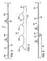
Fig. 3 is a fragmentary side elevation view of one embodiment of the separator of the present invention. -
Fig. 4 is an enlarged side elevation view of a portion of the separator ofFig. 3 . -
Fig. 5 is a fragmentary side elevation view of an implementation of the embodiment shown inFig. 3 including a shoulder region and mini-ribs. -
Fig. 6 is a diagram showing the separator of the present invention enveloping an electrode. - As shown in
Fig. 3 , abattery separator 20 of this invention is comprised of abackweb 22 having a first (upper)planar surface 24, a second (lower)planar surface 26, and respective first and secondlongitudinal edges 28 and 30 (shown inFig. 6 ) that are parallel to each other. The width of the separator of this invention can be any width desired by battery manufacturers. Typical separator widths are between about 115 mm and about 170 mm. The thickness ofbackweb 22 is typically between about 0.05 mm and about 0.20 mm. - Multiple
major ribs 34a - 34c project from upperplanar surface 24 ofseparator 20.Major ribs 34 are disposed in the longitudinal direction ofseparator 20, are positioned substantially parallel tolongitudinal edges Major ribs 34 are typically parallel to one another and toedges edges 28 and 30 (i.e., be diagonally disposed), or may be sinusoidal rather than straight.Major ribs 34 project above upperplanar surface 24 of baclcweb 22 a height of between about 0.50 mm and about 1.5 mm. The number of major ribs provided on a separator sheet varies according to the battery specifications; however, a preferred embodiment includes eight major ribs for each separator sheet. The distance between adjacentmajor ribs 34 is typically between about 10 mm and about 25 mm. - Submini-
ribs 40 are longitudinally disposed along the length ofseparator 20, and adjacent ones of them are substantially evenly spaced from each other. Submini-ribs 40 preferably extend from only one planar face ofseparator 20 and are preferably disposed substantially parallel to each other and toedges ribs 40 may have other configurations, such as inclined at an angle toedges ribs 40 preferably have rounded apexes, as shown inFig. 4 . The height of submini-ribs 40 above upperplanar surface 24 is selected in accordance with the desired height ofmajor ribs 34 and the desired compression resistance, but is preferably between about 0.025 mm and about 0.125 mm, and is most preferably about 0.08 mm. - There are preferably 20 submini-
ribs 40 provided between adjacentmajor ribs 34. The distance between adjacent submini-ribs is preferably between about 0.75 mm and about 0.96 mm, most preferably about 0.825 mm. Adjacent submini-ribs 40 are preferably uniformly spaced apart. -
Major ribs 34 and submini-ribs 40 are patterned such that only submini-ribs 40 of the separator-enveloped electrodes rest against mud rests 14 at the bottom ofcell compartment 10. In most prior art separators, the backweb of the separator rubbed against mud rests 14, which eventually resulted in the formation of a wear area, and over time, holes in the separator. In the separator of the present invention, only submini-ribs 40, which are thicker thanbackweb 22, contact mud rests 14. Thus the formation of a wear area, and eventually one or more holes, inseparator 20 is significantly delayed. -
Shoulder regions 50 are located between the lastmajor ribs 34 andedges Fig. 5 .Shoulder region 50 is the area in whichseparator 20 is sealed to form an enveloped electrode. The electrodes positioned adjacent to the separator sheets often have sharp metal protrusions called "bent wires" that can abrade and puncture the adjacent separator, thereby causing a short circuit and premature failure of the battery. Thusshoulder regions 50 are constructed to be more durable and puncture-resistant than the other portions ofseparator 20. Consequently, most shoulder regions include multiple mini-ribs 52. Further, anunribbed region 56 having a length between about 3.0 mm and 3.5 mm is preferably provided betweenmini-ribs 52 andmajor rib 34. Unlike submini-ribs 40, mini-ribs 52 have flattened upper surfaces, and the maximum preferred spacing between adjacent mini-ribs 52 is about 0.563 mm. Mini-ribs 52 are preferably longitudinally disposed, and substantially evenly spaced along the length ofseparator 20. Mini-ribs 52 are preferably disposed substantially parallel to one another and to longitudinal side edges 28 and 30, but may have other configurations, such as inclined at an angle to longitudinal side edges 28 and 30, or being sinusoidal rather than straight. Although they preferably extend from only one ofplanar surfaces shoulders region 50, and may be staggered so that a mini-rib on one planar surface is located between two mini-ribs located on the other planar surface. While mini-ribs 52 are not necessary to the present invention, their presence greatly increases the strength and durability of the shoulder region and thereby decreases the incidence of short-circuiting and premature battery failure. - A first exemplary microporous polyethylene battery separator of the present invention was made having the following characteristics, all dimensions being in millimeters:
Separator width: 162.56 Backweb thickness: 0.15 Major ribs: Number: 8 Height: 0.61 Width: 0.38 Spacing: 18.14 Submini-Ribs: Number: 20 (between adjacent major ribs) Height: 0.08 Width: 0.25 Spacing: 0.86 Mini-Ribs: Number: 18 (on each shoulder) Height: 0.10 Width: Width from Slope to Slope: 0.29 Width of the Flat Apex: 0.25 Spacing: 0.17 Shoulder Length: 17.78 (from last major rib to end of sheet) - A second exemplary microporous polyethylene battery separator of the present invention was made having the following characteristics, all dimensions being in millimeters:
Separator width: 162.56 Backweb thickness: 0.15 Major ribs: Number: 8 Height: 0.48 Width: 0.38 Spacing: 18.14 Submini-Ribs: Number: 20 (between adjacent major ribs) Height: 0.08 Width: 0.15 Spacing: 0.86 Mini-Ribs: Number: 18 (on each shoulder) Height: 0.10 Width: Width from Slope to Slope: 0.29 Width of the Flat Apex: 0.25 Spacing: 0.17 Shoulder Length: 17.78 (from last major rib to end of sheet) - A third exemplary microporous polyethylene battery separator of the present invention was made having the following characteristics, all dimensions being in millimeters:
Separator width: 162.56 Backweb thickness: 0.15 Major ribs: Number: 8 Height: 0.73 Width: 0.38 Spacing: 18.14 Submini-Ribs: Number: 20 (between adjacent major ribs) Height: 0.08 Width: 0.15 Spacing: 0.86 Mini-Ribs: Number: 18 (on each shoulder) Height: 0.10 Width: Width from Slope to Slope: 0.29 Width of the Flat Apex: 0.25 Spacing: 0.17 Shoulder Length: 17.78 (from last major rib to end of sheet) - A further advantage obtained in using the separator of the present invention is a reduction in or elimination of rib bending and/or flattening. In assembling a battery, the number of alternating enveloped and unenveloped electrodes required to form a cell are stacked together, compressed, and inserted into a cell compartment of a battery case. The compressive forces to which the separators are subjected can cause undesirable rib bending and/or flattening with conventional rib construction, especially at higher "overall" dimensions, i.e., rib heights. The rib configuration of the present invention reduces or eliminates such rib bending and/or flattening.
- The use of submini-
ribs 40 to provide higher major rib height without loss of compression resistance also allows the separators to be made with thinner backwebs, resulting in a consequent savings in the amount of material required to make a separator product of a specified square footage. - Although the separator of the invention is illustrated as having
major ribs 34 extending from only upperplanar surface 24 of thebackweb 22, the invention is intended to include a separator in whichmajor ribs 34 are formed on both upper and lowerplanar surfaces major ribs 34 extend from both planar surfaces ofseparator 20, the height ofmajor ribs 34 above upper and lowerplanar surfaces - Although the separator of the invention is illustrated as having submini-
ribs 40 extending from only upperplanar surface 24 of thebackweb 22, the invention is intended to include a separator in which submini-ribs 40 are formed on both upper and lowerplanar surfaces ribs 34 extend from both planar surfaces ofseparator 20, the height of submini-ribs 34 above upper and lowerplanar surfaces backweb 24, may be the same may be the same as, greater than, or lesser than the height of the submin-ribs on the other planar surface. - Although the separator of the invention is illustrated as having
mini-ribs 52 extending from only upperplanar surface 24 of thebackweb 22, the invention is intended to include a separator in which mini-ribs 52 are formed on both upper and lowerplanar surfaces separator 20, the height ofmini-ribs 52 above upper and lowerplanar surfaces - Although the invention has been described relative to forming ribs in a microporous polyethylene separator, because this is the principal type of separator material currently used by flooded cell-type lead acid battery manufacturers, any separator material which is porous, acid resistant, and capable of being permanently embossed may be used. These materials may be generally characterized as filled or unfilled films and nonwoven webs of thermoplastic or thermoset polymers. Suitable thermoplastic polymers include polymers and copolymers of ethylene, propylene, butylene, vinyl chloride, and styrene. Suitable thermoset compositions include phenolics, ethylene/propylene/diene, isoprene, butadiene, styrene, and similar thermosetting polymers.
- It will be obvious to those having skill in the art that many changes may be made to the details of the above-described embodiments of this invention without departing from the underlying principles thereof.
Claims (21)
- A lead acid battery having:a cell compartment that includesplanar mud rests that extend along and upward from the bottom of the cell compartment, the planar mud rests configured to prevent contact between an electrode and a mud precipitate that is formed during operation of the lead acid battery at the bottom of the cell compartment;porous, acid-resistant battery separators, each battery separator comprising:characterized in thata backweb having an upper planar surface and a lower planar surface separated by a backweb thickness;multiple spaced-apart major ribs extending a major rib height above the backweb and longitudinally disposed along the length of one of the upper planar surface or the lower planar surface to facilitate electrode spacing and to provide a space in which an electrolyte can reside;multiple submini-ribs extending a submini-rib height above the backweb and longitudinally disposed along the length of one of the upper planar surface or the lower planar surface such that a number of the multiple submini-ribs are positioned between adjacent major ribs, the submini-ribs having a submini-rib thickness that is greater than the backweb thickness,
the battery separator's submini-rib thickness and the number of and spacing between ones of the submini-ribs positioned between adjacent major ribs are patterned such that the submini-ribs are a primary point of contact between the battery separator and the mud rests and thereby delay the formation of a wear area in the battery separator during operation of the lead acid battery. - A porous, acid-resistant battery separator for use in a lead acid battery according to claim 1, the battery separator comprising:a backweb having an upper planar surface and a lower planar surface separated by a backweb thickness;multiple spaced-apart major ribs extending a major rib height above the backweb and longitudinally disposed along the length of one of the upper planar surface or the lower planar surface to facilitate electrode spacing and to provide a space in which an electrolyte can reside;multiple submini-ribs extending a submini-rib height above the backweb and longitudinally disposed along the length of one of the upper planar surface or the lower planar surface such that a number of the multiple submini-ribs are positioned between adjacent major ribs, the submini-ribs having a submini-rib thickness that is greater than the backweb thickness,characterized in that
the submini-rib thickness and the number of and spacing between ones of the submini-ribs positioned between adjacent major ribs are patterned such that the submini-ribs are a primary point of contact between the battery separator and the mud rests and thereby delay the formation of a wear area in the battery separator during operation of the lead acid battery. - The battery separator of claim 2, in which the submini-ribs are longitudinally disposed along the length of both the upper planar surface and the lower planar surface.
- The battery separator of claim 2 or 3, in which the backweb further includes opposed longitudinal edges that are in parallel alignment with the submini-ribs.
- The battery separator of one of claims 2 to 4, in which the backweb further includes opposed longitudinal edges and in which the submini-ribs are positioned at an angle to the opposed longitudinal edges.
- The battery separator of one of claims 2 to 5, in which adjacent submini ribs are mutually spaced apart by a distance that is between about 0,75 mm to about 0,96 mm.
- The battery separator of one of claims 2 to 6, in which the submini-rib height is between about 0,025 mm to about 0,125 mm.
- The battery separator of one of claims 2 to 7, in which the submini-ribs include rounded apexes.
- The battery separator of one of claims 2 to 8, in which the backweb thickness is between about 0,05 mm and about 0,20 mm.
- The battery separator of one of claims 2 to 9, in which the submini-ribs have a submini-rib width that is between about 0,10 mm and about 0,30 mm.
- The battery separator of one of claims 2 to 10, in which the major ribs are longitudinally disposed along the length of both the upper planar surface and the lower planar surface.
- The battery separator of one of claims 2 to 11, in which the backweb further includes opposed longitudinal edges that are in parallel alignment with the major ribs.
- The battery separator of one of claims 2 to 12, in which the backweb further includes opposed longitudinal edges and in which the major ribs are positioned at an angle to the opposed longitudinal edges.
- The battery separator of one of claims 2 to 13, in which adjacent major ribs are spaced apart a distance between about 10 mm and to about 25 mm.
- The battery separator of one of claims 2 to 14, in which the major rib height is between about 0,5 mm to about 1,5 mm.
- The battery separator of one of claims 2 to 15, in which between fifteen and twenty-five submini-ribs lie between adjacent major ribs.
- The battery separator of one of claims 2 to 16, further including a shoulder region positioned between a terminal major rib and one of two opposed longitudinal edges, the shoulder region having increased puncture resistance and including multiple mini-ribs.
- The battery separator of claim 17, in which the distance between adjacent mini-ribs is between about 0,45 mm and about 0,60 mm.
- The battery separator of claim 17 or 18, in which the mini-ribs include flattened upper surfaces.
- The battery separator of one of claims 17 to 19, in which the mini-ribs are positioned on both the upper planar surface and lower planar surface of the backweb.
- Method of constructing a battery separator with submini-ribs for use in a lead acid battery having a cell compartment suitable for including planar mud rests that extend along and upward from the bottom of the cell compartment, with the following steps:configuring mud rests to prevent contact between an electrode and a mud precipitate that is formed during operation of the lead acid battery and that accumulates at the bottom of the cell compartment,adding the mud rests to the bottom of the cell compartment,characterized by the following step:defining a submini-rib thickness, a number of and a spacing between ones of the submini-ribs cooperating to cause the submini-ribs to be a primary point of contact between the battery separator and the mud rests.
Applications Claiming Priority (5)
| Application Number | Priority Date | Filing Date | Title |
|---|---|---|---|
| US36855302P | 2002-03-29 | 2002-03-29 | |
| US368553P | 2002-03-29 | ||
| US383316 | 2003-03-07 | ||
| US10/383,316 US6641954B2 (en) | 2002-03-29 | 2003-03-07 | Battery separator with mud rest protectors |
| PCT/US2003/009658 WO2003083966A2 (en) | 2002-03-29 | 2003-03-28 | Battery separator with mud rest protectors |
Publications (3)
| Publication Number | Publication Date |
|---|---|
| EP1493201A2 EP1493201A2 (en) | 2005-01-05 |
| EP1493201A4 EP1493201A4 (en) | 2005-11-16 |
| EP1493201B1 true EP1493201B1 (en) | 2008-06-25 |
Family
ID=28457237
Family Applications (1)
| Application Number | Title | Priority Date | Filing Date |
|---|---|---|---|
| EP03716893A Expired - Lifetime EP1493201B1 (en) | 2002-03-29 | 2003-03-28 | Battery separator with mud rest protectors |
Country Status (8)
| Country | Link |
|---|---|
| US (1) | US6641954B2 (en) |
| EP (1) | EP1493201B1 (en) |
| AT (1) | ATE399372T1 (en) |
| AU (1) | AU2003220579A1 (en) |
| DE (1) | DE60321776D1 (en) |
| ES (1) | ES2309309T3 (en) |
| MX (1) | MXPA04009017A (en) |
| WO (1) | WO2003083966A2 (en) |
Families Citing this family (14)
| Publication number | Priority date | Publication date | Assignee | Title |
|---|---|---|---|---|
| RU2311734C1 (en) * | 2006-03-06 | 2007-11-27 | Государственное образовательное учреждение высшего профессионального образования Академия Федеральной службы охраны Российской Федерации (Академия ФСО России) | Broadband receiving-transmitting device |
| CN104218206B (en) * | 2008-07-10 | 2018-01-23 | 约翰逊控制技术公司 | The battery separator of reinforcement |
| US8404378B2 (en) * | 2009-04-30 | 2013-03-26 | Daramic Llc | Battery separator for a storage battery |
| US9666848B2 (en) | 2011-05-20 | 2017-05-30 | Dreamweaver International, Inc. | Single-layer lithium ion battery separator |
| US9461291B2 (en) | 2011-11-21 | 2016-10-04 | Daramic, Llc | Embossed separators, batteries and methods |
| US10700326B2 (en) | 2012-11-14 | 2020-06-30 | Dreamweaver International, Inc. | Single-layer lithium ion battery separators exhibiting low shrinkage rates at high temperatures |
| US10607790B2 (en) | 2013-03-15 | 2020-03-31 | Dreamweaver International, Inc. | Direct electrolyte gelling via battery separator composition and structure |
| WO2015148305A1 (en) | 2014-03-22 | 2015-10-01 | Hollingsworth & Vose Company | Battery separators having a low apparent density |
| US10230088B1 (en) | 2015-01-30 | 2019-03-12 | Johnson Controls Technology Company | Battery electrode assembly, separator and method of making same |
| WO2016134222A1 (en) | 2015-02-19 | 2016-08-25 | Hollingsworth & Vose Company | Battery separators comprising chemical additives and/or other components |
| CN108292724B (en) * | 2015-10-07 | 2022-05-13 | 达拉米克有限责任公司 | Lead acid battery separator with improved performance, battery thereof, vehicle having the battery, and related methods |
| CN112088460A (en) * | 2018-03-09 | 2020-12-15 | 达拉米克有限责任公司 | Lead-acid battery separator and related method |
| RU194039U1 (en) * | 2019-06-25 | 2019-11-26 | Федеральное государственное казенное военное образовательное учреждение высшего образования "Рязанское гвардейское высшее воздушно-десантное ордена Суворова дважды Краснознаменное командное училище имени генерала армии В.Ф. Маргелова" Министерства обороны Российской Федерации | DEVICE FOR MANAGING MULTIPLE ACCESS TO A RADIO CHANNEL WITH A Frequency Response Switching System (BCH) FOR PACKAGE TRANSMISSION OF MESSAGES |
| US12401090B2 (en) | 2020-02-10 | 2025-08-26 | Hollingsworth & Vose Company | Embossed separators |
Family Cites Families (9)
| Publication number | Priority date | Publication date | Assignee | Title |
|---|---|---|---|---|
| US4026000A (en) | 1976-07-15 | 1977-05-31 | Globe-Union Inc. | Apparatus for producing enveloped battery plates |
| US4963444A (en) | 1988-05-31 | 1990-10-16 | Globe-Union Inc. | Internal hydrostatic pump for a mobile vehicle battery |
| US5096787A (en) | 1990-08-03 | 1992-03-17 | Globe-Union Inc. | Hydrostatic pump with static resistance for a mobile vehicle battery |
| US5679479A (en) | 1996-05-08 | 1997-10-21 | Amtek Research International Llc | Battery separator |
| US5789103A (en) | 1997-04-11 | 1998-08-04 | Amtek Research International Llc | Battery separator and method of making |
| US6001503A (en) * | 1997-08-26 | 1999-12-14 | General Motors Corporation | Battery separator having a puncture-proof border |
| US6132899A (en) * | 1997-10-20 | 2000-10-17 | Amtek Research International Llc | Battery Separator having different size ribs and method of making the same |
| KR100311945B1 (en) * | 1998-09-18 | 2001-11-03 | 모리시타 요이찌 | Lead acid storage battery |
| US6410183B2 (en) * | 1999-04-16 | 2002-06-25 | Daniel E. Weerts | Battery separator with improved shoulders |
-
2003
- 2003-03-07 US US10/383,316 patent/US6641954B2/en not_active Expired - Lifetime
- 2003-03-28 DE DE60321776T patent/DE60321776D1/de not_active Expired - Lifetime
- 2003-03-28 ES ES03716893T patent/ES2309309T3/en not_active Expired - Lifetime
- 2003-03-28 EP EP03716893A patent/EP1493201B1/en not_active Expired - Lifetime
- 2003-03-28 MX MXPA04009017A patent/MXPA04009017A/en active IP Right Grant
- 2003-03-28 AU AU2003220579A patent/AU2003220579A1/en not_active Abandoned
- 2003-03-28 AT AT03716893T patent/ATE399372T1/en not_active IP Right Cessation
- 2003-03-28 WO PCT/US2003/009658 patent/WO2003083966A2/en not_active Ceased
Also Published As
| Publication number | Publication date |
|---|---|
| DE60321776D1 (en) | 2008-08-07 |
| WO2003083966A3 (en) | 2003-11-13 |
| EP1493201A4 (en) | 2005-11-16 |
| EP1493201A2 (en) | 2005-01-05 |
| AU2003220579A8 (en) | 2003-10-13 |
| ATE399372T1 (en) | 2008-07-15 |
| US20030186126A1 (en) | 2003-10-02 |
| ES2309309T3 (en) | 2008-12-16 |
| MXPA04009017A (en) | 2005-01-25 |
| WO2003083966A2 (en) | 2003-10-09 |
| AU2003220579A1 (en) | 2003-10-13 |
| US6641954B2 (en) | 2003-11-04 |
Similar Documents
| Publication | Publication Date | Title |
|---|---|---|
| EP1493201B1 (en) | Battery separator with mud rest protectors | |
| CA2252946C (en) | Battery separator with porous backweb and ribbing | |
| AU747268B2 (en) | Battery separator | |
| US5789103A (en) | Battery separator and method of making | |
| JP7382569B2 (en) | Battery electrode, battery, and method for manufacturing battery electrode | |
| US6410183B2 (en) | Battery separator with improved shoulders | |
| US6132899A (en) | Battery Separator having different size ribs and method of making the same | |
| US7425387B2 (en) | Separator for a lead storage battery | |
| KR20240023075A (en) | Negative plate, electrode assembly including the same, and method of manufacturing the negative plate and electorde assembly | |
| CN102738470B (en) | Lead accumulator grid, positive plate, pole plate group, lead accumulator and manufacture method thereof | |
| JP2000182593A (en) | Bag-like separator with ribs for lead-acid battery | |
| WO2000023267A1 (en) | Battery separator | |
| WO2000024067A1 (en) | Battery separator and method of making | |
| MXPA99001084A (en) | Bat separator | |
| MXPA98009038A (en) | Bater separator | |
| MXPA99001085A (en) | Battery separator and method of fabricac |
Legal Events
| Date | Code | Title | Description |
|---|---|---|---|
| PUAI | Public reference made under article 153(3) epc to a published international application that has entered the european phase |
Free format text: ORIGINAL CODE: 0009012 |
|
| 17P | Request for examination filed |
Effective date: 20041006 |
|
| AK | Designated contracting states |
Kind code of ref document: A2 Designated state(s): AT BE BG CH CY CZ DE DK EE ES FI FR GB GR HU IE IT LI LU MC NL PT RO SE SI SK TR |
|
| AX | Request for extension of the european patent |
Extension state: AL LT LV MK |
|
| A4 | Supplementary search report drawn up and despatched |
Effective date: 20051005 |
|
| RIC1 | Information provided on ipc code assigned before grant |
Ipc: 7H 01M 2/18 B Ipc: 7H 01M 10/06 A |
|
| 17Q | First examination report despatched |
Effective date: 20060607 |
|
| GRAP | Despatch of communication of intention to grant a patent |
Free format text: ORIGINAL CODE: EPIDOSNIGR1 |
|
| GRAS | Grant fee paid |
Free format text: ORIGINAL CODE: EPIDOSNIGR3 |
|
| GRAA | (expected) grant |
Free format text: ORIGINAL CODE: 0009210 |
|
| AK | Designated contracting states |
Kind code of ref document: B1 Designated state(s): AT BE BG CH CY CZ DE DK EE ES FI FR GB GR HU IE IT LI LU MC NL PT RO SE SI SK TR |
|
| AX | Request for extension of the european patent |
Extension state: AL LT LV MK |
|
| REG | Reference to a national code |
Ref country code: GB Ref legal event code: FG4D |
|
| REG | Reference to a national code |
Ref country code: CH Ref legal event code: EP |
|
| REF | Corresponds to: |
Ref document number: 60321776 Country of ref document: DE Date of ref document: 20080807 Kind code of ref document: P |
|
| REG | Reference to a national code |
Ref country code: IE Ref legal event code: FG4D |
|
| PG25 | Lapsed in a contracting state [announced via postgrant information from national office to epo] |
Ref country code: FI Free format text: LAPSE BECAUSE OF FAILURE TO SUBMIT A TRANSLATION OF THE DESCRIPTION OR TO PAY THE FEE WITHIN THE PRESCRIBED TIME-LIMIT Effective date: 20080625 Ref country code: SI Free format text: LAPSE BECAUSE OF FAILURE TO SUBMIT A TRANSLATION OF THE DESCRIPTION OR TO PAY THE FEE WITHIN THE PRESCRIBED TIME-LIMIT Effective date: 20080625 |
|
| PG25 | Lapsed in a contracting state [announced via postgrant information from national office to epo] |
Ref country code: AT Free format text: LAPSE BECAUSE OF FAILURE TO SUBMIT A TRANSLATION OF THE DESCRIPTION OR TO PAY THE FEE WITHIN THE PRESCRIBED TIME-LIMIT Effective date: 20080625 Ref country code: NL Free format text: LAPSE BECAUSE OF FAILURE TO SUBMIT A TRANSLATION OF THE DESCRIPTION OR TO PAY THE FEE WITHIN THE PRESCRIBED TIME-LIMIT Effective date: 20080625 |
|
| REG | Reference to a national code |
Ref country code: ES Ref legal event code: FG2A Ref document number: 2309309 Country of ref document: ES Kind code of ref document: T3 |
|
| NLV1 | Nl: lapsed or annulled due to failure to fulfill the requirements of art. 29p and 29m of the patents act | ||
| PG25 | Lapsed in a contracting state [announced via postgrant information from national office to epo] |
Ref country code: SE Free format text: LAPSE BECAUSE OF FAILURE TO SUBMIT A TRANSLATION OF THE DESCRIPTION OR TO PAY THE FEE WITHIN THE PRESCRIBED TIME-LIMIT Effective date: 20080925 Ref country code: PT Free format text: LAPSE BECAUSE OF FAILURE TO SUBMIT A TRANSLATION OF THE DESCRIPTION OR TO PAY THE FEE WITHIN THE PRESCRIBED TIME-LIMIT Effective date: 20081125 |
|
| PG25 | Lapsed in a contracting state [announced via postgrant information from national office to epo] |
Ref country code: RO Free format text: LAPSE BECAUSE OF FAILURE TO SUBMIT A TRANSLATION OF THE DESCRIPTION OR TO PAY THE FEE WITHIN THE PRESCRIBED TIME-LIMIT Effective date: 20080625 Ref country code: SK Free format text: LAPSE BECAUSE OF FAILURE TO SUBMIT A TRANSLATION OF THE DESCRIPTION OR TO PAY THE FEE WITHIN THE PRESCRIBED TIME-LIMIT Effective date: 20080625 Ref country code: BE Free format text: LAPSE BECAUSE OF FAILURE TO SUBMIT A TRANSLATION OF THE DESCRIPTION OR TO PAY THE FEE WITHIN THE PRESCRIBED TIME-LIMIT Effective date: 20080625 |
|
| PG25 | Lapsed in a contracting state [announced via postgrant information from national office to epo] |
Ref country code: BG Free format text: LAPSE BECAUSE OF FAILURE TO SUBMIT A TRANSLATION OF THE DESCRIPTION OR TO PAY THE FEE WITHIN THE PRESCRIBED TIME-LIMIT Effective date: 20080925 Ref country code: EE Free format text: LAPSE BECAUSE OF FAILURE TO SUBMIT A TRANSLATION OF THE DESCRIPTION OR TO PAY THE FEE WITHIN THE PRESCRIBED TIME-LIMIT Effective date: 20080625 Ref country code: DK Free format text: LAPSE BECAUSE OF FAILURE TO SUBMIT A TRANSLATION OF THE DESCRIPTION OR TO PAY THE FEE WITHIN THE PRESCRIBED TIME-LIMIT Effective date: 20080625 |
|
| PLBE | No opposition filed within time limit |
Free format text: ORIGINAL CODE: 0009261 |
|
| STAA | Information on the status of an ep patent application or granted ep patent |
Free format text: STATUS: NO OPPOSITION FILED WITHIN TIME LIMIT |
|
| 26N | No opposition filed |
Effective date: 20090326 |
|
| PG25 | Lapsed in a contracting state [announced via postgrant information from national office to epo] |
Ref country code: IT Free format text: LAPSE BECAUSE OF FAILURE TO SUBMIT A TRANSLATION OF THE DESCRIPTION OR TO PAY THE FEE WITHIN THE PRESCRIBED TIME-LIMIT Effective date: 20080625 |
|
| PG25 | Lapsed in a contracting state [announced via postgrant information from national office to epo] |
Ref country code: MC Free format text: LAPSE BECAUSE OF NON-PAYMENT OF DUE FEES Effective date: 20090331 |
|
| REG | Reference to a national code |
Ref country code: CH Ref legal event code: PL |
|
| GBPC | Gb: european patent ceased through non-payment of renewal fee |
Effective date: 20090328 |
|
| REG | Reference to a national code |
Ref country code: IE Ref legal event code: MM4A |
|
| PG25 | Lapsed in a contracting state [announced via postgrant information from national office to epo] |
Ref country code: LI Free format text: LAPSE BECAUSE OF NON-PAYMENT OF DUE FEES Effective date: 20090331 Ref country code: IE Free format text: LAPSE BECAUSE OF NON-PAYMENT OF DUE FEES Effective date: 20090328 Ref country code: CH Free format text: LAPSE BECAUSE OF NON-PAYMENT OF DUE FEES Effective date: 20090331 |
|
| PG25 | Lapsed in a contracting state [announced via postgrant information from national office to epo] |
Ref country code: GB Free format text: LAPSE BECAUSE OF NON-PAYMENT OF DUE FEES Effective date: 20090328 |
|
| PG25 | Lapsed in a contracting state [announced via postgrant information from national office to epo] |
Ref country code: GR Free format text: LAPSE BECAUSE OF FAILURE TO SUBMIT A TRANSLATION OF THE DESCRIPTION OR TO PAY THE FEE WITHIN THE PRESCRIBED TIME-LIMIT Effective date: 20080926 |
|
| PG25 | Lapsed in a contracting state [announced via postgrant information from national office to epo] |
Ref country code: LU Free format text: LAPSE BECAUSE OF NON-PAYMENT OF DUE FEES Effective date: 20090328 |
|
| PG25 | Lapsed in a contracting state [announced via postgrant information from national office to epo] |
Ref country code: HU Free format text: LAPSE BECAUSE OF FAILURE TO SUBMIT A TRANSLATION OF THE DESCRIPTION OR TO PAY THE FEE WITHIN THE PRESCRIBED TIME-LIMIT Effective date: 20081226 |
|
| PG25 | Lapsed in a contracting state [announced via postgrant information from national office to epo] |
Ref country code: TR Free format text: LAPSE BECAUSE OF FAILURE TO SUBMIT A TRANSLATION OF THE DESCRIPTION OR TO PAY THE FEE WITHIN THE PRESCRIBED TIME-LIMIT Effective date: 20080625 |
|
| PG25 | Lapsed in a contracting state [announced via postgrant information from national office to epo] |
Ref country code: CY Free format text: LAPSE BECAUSE OF FAILURE TO SUBMIT A TRANSLATION OF THE DESCRIPTION OR TO PAY THE FEE WITHIN THE PRESCRIBED TIME-LIMIT Effective date: 20080625 |
|
| REG | Reference to a national code |
Ref country code: FR Ref legal event code: PLFP Year of fee payment: 14 |
|
| REG | Reference to a national code |
Ref country code: FR Ref legal event code: PLFP Year of fee payment: 15 |
|
| REG | Reference to a national code |
Ref country code: FR Ref legal event code: PLFP Year of fee payment: 16 |
|
| PGFP | Annual fee paid to national office [announced via postgrant information from national office to epo] |
Ref country code: CZ Payment date: 20190314 Year of fee payment: 17 Ref country code: DE Payment date: 20190312 Year of fee payment: 17 Ref country code: FR Payment date: 20190327 Year of fee payment: 17 |
|
| PGFP | Annual fee paid to national office [announced via postgrant information from national office to epo] |
Ref country code: ES Payment date: 20190401 Year of fee payment: 17 |
|
| REG | Reference to a national code |
Ref country code: DE Ref legal event code: R119 Ref document number: 60321776 Country of ref document: DE |
|
| PG25 | Lapsed in a contracting state [announced via postgrant information from national office to epo] |
Ref country code: CZ Free format text: LAPSE BECAUSE OF NON-PAYMENT OF DUE FEES Effective date: 20200328 |
|
| PG25 | Lapsed in a contracting state [announced via postgrant information from national office to epo] |
Ref country code: FR Free format text: LAPSE BECAUSE OF NON-PAYMENT OF DUE FEES Effective date: 20200331 Ref country code: DE Free format text: LAPSE BECAUSE OF NON-PAYMENT OF DUE FEES Effective date: 20201001 |
|
| REG | Reference to a national code |
Ref country code: ES Ref legal event code: FD2A Effective date: 20210806 |
|
| PG25 | Lapsed in a contracting state [announced via postgrant information from national office to epo] |
Ref country code: ES Free format text: LAPSE BECAUSE OF NON-PAYMENT OF DUE FEES Effective date: 20200329 |