EP1492007A2 - System and method of controlling computer supporting multiple operation modes - Google Patents
System and method of controlling computer supporting multiple operation modes Download PDFInfo
- Publication number
- EP1492007A2 EP1492007A2 EP20040076739 EP04076739A EP1492007A2 EP 1492007 A2 EP1492007 A2 EP 1492007A2 EP 20040076739 EP20040076739 EP 20040076739 EP 04076739 A EP04076739 A EP 04076739A EP 1492007 A2 EP1492007 A2 EP 1492007A2
- Authority
- EP
- European Patent Office
- Prior art keywords
- operation mode
- computer
- mode
- modes
- application
- Prior art date
- Legal status (The legal status is an assumption and is not a legal conclusion. Google has not performed a legal analysis and makes no representation as to the accuracy of the status listed.)
- Granted
Links
Images


Classifications
-
- G—PHYSICS
- G06—COMPUTING; CALCULATING OR COUNTING
- G06F—ELECTRIC DIGITAL DATA PROCESSING
- G06F11/00—Error detection; Error correction; Monitoring
- G06F11/07—Responding to the occurrence of a fault, e.g. fault tolerance
- G06F11/14—Error detection or correction of the data by redundancy in operation
- G06F11/1497—Details of time redundant execution on a single processing unit
-
- G—PHYSICS
- G06—COMPUTING; CALCULATING OR COUNTING
- G06F—ELECTRIC DIGITAL DATA PROCESSING
- G06F11/00—Error detection; Error correction; Monitoring
- G06F11/07—Responding to the occurrence of a fault, e.g. fault tolerance
- G06F11/0703—Error or fault processing not based on redundancy, i.e. by taking additional measures to deal with the error or fault not making use of redundancy in operation, in hardware, or in data representation
- G06F11/0751—Error or fault detection not based on redundancy
- G06F11/0754—Error or fault detection not based on redundancy by exceeding limits
- G06F11/0757—Error or fault detection not based on redundancy by exceeding limits by exceeding a time limit, i.e. time-out, e.g. watchdogs
Definitions
- the present invention relates to a system and method of controlling a computer supporting multiple operation modes, and more particularly to a system and method of operating a computer capable of operating in multiple operation modes and controlling the operation of such computer by a mode controller and a watchdog monitor module.
- the operating system of a computer can execute numerous multimedia software, such as music player, video player, TV player, radio receiver application, image capturer and explorer, and video/audio recording programs, and perform associated multimedia functions using related peripheral appliances and corresponding drivers.
- multimedia software such as music player, video player, TV player, radio receiver application, image capturer and explorer, and video/audio recording programs, and perform associated multimedia functions using related peripheral appliances and corresponding drivers.
- conventional configurations of a computer provide a fixed number of specific control means corresponding to available operation modes.
- the computer can execute related software and operates in the designated operation mode by activating corresponding control means.
- Conventional methods are simple, however, the number of the control means available for use in a computer is limited and must be preset in advance, such that extension of the maneuverability of the computer is limited.
- the manufacturer of the computer must produce related hardware to support the computer for operating in multiple operation modes, thereby increasing the manufacturing cost.
- a preferred embodiment of the present invention provides a system and method for controlling a computer supporting multiple operation modes.
- the system according to the present invention includes a mode controller for generating a combination of electric potentials on two connection terminals, and an additional microprocessor.
- the additional microprocessor includes a storage module including a mode list recording a plurality of operation modes, and a pointer for designating one of the operation modes in the mode list as a first operation mode for the computer.
- the additional microprocessor also includes a detection module to detect the combination of the electric potentials at a first sampling point, and determines a shift direction of the mode controller according thereto.
- the additional microprocessor further includes a control module to select a second operation mode adjacent to the first operation mode in the mode list according to the shift direction, check the disparity between the first operation mode and the second operation mode, provide a control signal to the computer according to the check result, direct the computer to reboot or execute an application specific to the second operation mode, and subsequently enable the computer to operate in the second operation mode.
- the method of controlling the computer supporting multiple operation modes uses an additional microprocessor to detect a combination of the electric potentials triggered by a mode controller at a first sampling point, and then determines a shift direction of the mode controller according thereto. Then, a second operation mode adjacent to the first operation mode in the mode list is selected according to the shift direction. Then, the additional microprocessor checks the disparity between the first operation mode and the second operation mode, provides a control signal to the computer according to the check result, and directs the computer to reboot or execute an application specific to the second operation mode, and subsequently enables the computer to operate in the second operation mode.
- the detection module stops detecting the combination of the electric potentials within a first predetermined period after the first sampling point, and resumes to detect the combination of the electric potentials at a second sampling point after the first predetermined period is expired and before a second predetermined period is reached. If the combination of the electric potentials detected at the first sampling point and the combination of the electric potentials detected at the second sampling point are different with each other, the detection module ignores the shift direction corresponding to the combination of electric potentials detected at the second sampling point.
- a further aspect of the present invention is directed to an application management system that is used to monitor the execution of an application when the computer is operating in either a normal operation mode or a specific operation mode, and protect the computer from crash due to the abnormality encountered during the execution of the application.
- the application management system is implemented by a watchdog monitor module being embedded in the additional microprocessor. If the execution of an application is abnormal, the watchdog monitor module enables the computer to reboot, and instructs a first microprocessor (the central processing unit of the computer) of the computer to re-execute the application.
- the watchdog monitor module may alternatively adopt two methodologies to monitor the execution of the application and protect the computer from system crash.
- the application is configured to send a LIVE signal to the watchdog monitor module when a first predetermined time interval is reached, and if the LIVE signal is not received from the application within a second predetermined time interval, the watchdog monitor module determines that the execution status of the application becomes abnormal and thus enables the computer to reboot or re-execute the application.
- the watchdog monitor module is configured to send a CONFIRMATION signal to the application when a first predetermined time interval is reached, and the application is configured to return a SURVIVING signal to the watchdog monitor module in response to the CONFIRMATION signal, wherein if the SURVIVING signal is not received from the application within a second predetermined time interval, the watchdog monitor module determines that the execution status of the application becomes abnormal and thus enables the computer to reboot and re-execute the application.
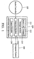
- Fig. 1 illustrates a generalized architecture of the system of controlling a computer supporting multiple operation modes according to the present invention.
- the system of controlling a computer supporting multiple operation modes is applied to a computer 300.
- the system includes a mode controller 100 and an additional microprocessor 200.
- the mode controller 100 selects the operation mode of the computer 300.
- the mode controller 100 can be a knob controller constructed on the computer host. With the rotational force being applied to the mode controller 100, the computer 300 may operate in a normal operation mode or one of the sub-modes subjected to a multimedia mode class, such as a music playing mode, a video playing mode, a TV broadcasting mode, a radio receiving mode, and an image exploring mode.
- a multimedia mode class such as a music playing mode, a video playing mode, a TV broadcasting mode, a radio receiving mode, and an image exploring mode.
- the computer is configured to execute a sub-mode application specific to the selected sub-mode, for example, the computer 300 may run a music player application when the operation mode of the computer 300 is selected as a music playing mode, a video player application when the operation mode of the computer 300 is selected as a video playing mode, a TV viewer application when the operation mode of the computer 300 is selected as a TV broadcasting mode, an Internet radio application when the operation mode of the computer 300 is selected as a radio receiving mode, and a photo explorer application when the operation mode of the computer 300 is selected as an image exploring mode.
- a sub-mode application specific to the selected sub-mode for example, the computer 300 may run a music player application when the operation mode of the computer 300 is selected as a music playing mode, a video player application when the operation mode of the computer 300 is selected as a video playing mode, a TV viewer application when the operation mode of the computer 300 is selected as a TV broadcasting mode, an Internet radio application when the operation mode of the computer 300 is selected as a radio receiving mode, and a photo
- sub-mode applications being respectively specific to an individual sub-mode are executed by the computer 300 under a purified operating environment, that is, the computer 300 is running by a simplified version of an operating system with only the corresponding sub-mode application and basic system configuration settings loaded into system, while hardware device drivers, other application programs, plug-and-play utilities, are unloaded or disabled when the computer 300 is operating in a selected sub-mode.
- the operation principle of the mode controller 100 is illustrated in Fig. 2.
- a first connection terminal A and a second connection terminal B can be triggered to raise its corresponding electric potential.
- the switch S of the controller 100 rotates, a first connection terminal A and a second connection terminal B can be triggered to raise its corresponding electric potential.
- the switch S of the controller 100 rotates, a first connection terminal A and a second connection terminal B can be triggered to raise its corresponding electric potential.
- Fig. 3A in which C represents a sampling point for detection.
- C represents a sampling point for detection.
- D represents a sampling point for detection.
- the additional microprocessor basically includes a storage module 210, a detection module 220 and a control module 230.
- the storage module 210 includes a mode list 211 and a pointer (flag) 212, in which the mode list 211 records the available operation modes provided by the computer 300, and the pointer 212 selects one of the available operation modes and designates the selected operation mode as the current operation mode of the computer 300. Note that in order to add a new operation mode, the manufacturer may add the desired operation modes to the mode list 211 without the requirement of additional hardware support.
- the detection module 220 detects the state of the mode controller 100, that is, the detection module 220 detects the combination of the electric potentials on the first connection terminal A and the second connection terminal B, and determines a shift direction of the mode controller 100 according thereto. It should be noted that, in general, two successive sampling points are used for accurate detection, such as sampling points C and E in Fig. 4, and the detection is valid if the detection results respectively evaluated at the two sampling points match with each other.
- the rotation counterforce applied to the mode controller 100 may likely to cause electric potentials on the two connection terminals A and B of the mode controller 1010, as illustrated in Fig. 5.
- the determination of the shift direction of the mode controller 100 may be wrong if the detection is performed at sampling points F and G. Therefore, the present invention provides two modes to solve the problem.
- the detection module 220 may ignore all triggers of the connection terminals, that is, the detection module 220 stops detecting the combination of the electric potentials within a first predetermined period, such as 200ms, after the first sample point.
- the detection module 220 may ignore the detection result performed at a succeeding sampling point if the shift direction corresponding to the first sampling point is not the same as that of a succeeding sampling point within a second predetermined period after the first sampling point. It should be noted that the two modes could be adopted synthetically or alternatively.
- Fig. 6 shows the processing of the detection module 220 according to the present invention.
- the detection module 220 detects the combination of the electric potentials on the first connection terminal A and the second connection terminal B. If the combination of the electric potentials on the connection terminals A and B does not change and the electric potentials of the two connection terminals both stay low (No in step S602), the flow returns to step S601. If the combination of the electric potentials of the connection terminals A and B changes (Yes in step S602), in step S603, it determines whether the detection is occurred within the second predetermined period after a first detection.
- step S604 the detection module 220 determines a shift direction of the mode controller 100 according thereto, and in step S605, stops detecting the combination of the electric potentials within the first predetermined period. After the first predetermined period expires, the flow returns to step S601.
- step S606 the detection module 220 checks whether the combination of the electric potential is different from the prior one. If not (No in step S606), in step S604, the detection module 220 determines a shift direction of the mode controller according thereto, and performs the process of step S605. If so (Yes in step S606), in step S607, the detection module 220 ignores the combination of the electric potentials of this detection, and the flow returns to step S601.
- the control module 230 selects a second operation mode adjacent to the first operation mode designated by the pointer 212 in the mode list 211 according to the control direction determined by the detection module 220.
- the operation mode following the first operation mode in the mode list 211 is selected if the shift direction of the mode controller 100 is clockwise, and the operation mode preceding the first operation mode in the mode list 211 is selected if the shift direction of the mode controller 100 is counterclockwise.
- the control module 230 also checks the disparity between the first operation mode and the second operation mode to provide a control signal to the computer 300 according to the check result, thereby directing the computer 300 to reboot or execute an application specific to the second operation mode, and subsequently enables the computer to operate in the second operation mode.
- the control module 230 If the first operation mode is a normal operation mode and the second operation mode is one of the sub-modes of the multimedia mode class, the control module 230 generates a control signal to a power circuit (not shown in figures) of the computer 300, thereby directing the computer 300 to reboot and operating in the second operation mode, and executing the application specific to the second operation mode (selected sub-mode of the multimedia mode class). If the first operation mode is one of the sub-modes of the multimedia mode class and the second operation mode is the normal operation mode, the control module 230 generates a control signal to the power circuit of the computer 300, thereby directing the computer 300 to reboot and operate in the normal operation mode.
- the control module 230 If the first operation mode and the second operation mode are different sub-modes of the multimedia mode class respectively, the control module 230 generates a control signal to the computer 300, thereby directing the computer 300 to operate in the second operation mode, and execute the application specific to the second operation mode. It should be noted that the number of applications may be coincident to the number of the sub-modes of the multimedia mode class, and each sub-mode executes a specific application under a purified operating environment.
- a display screen (not shown) can be provided on the computer 300 to show the current operation mode of the computer 300. If the mode controller 100 rotates, the control module 230 may send a signal to display the related information of the second operation mode, such as the name of the operation mode. Further, the operation modes can be selected in order using the mode controller 100. It should be noted that the content shown on the display screen is allowed to change in a preset period, such as 2 seconds, and the additional microprocessor will direct the computer to change operation mode until the mode controller stops.
- Fig. 7 shows the method for operation mode control according to the present invention.
- step S701 the detection module 220 of the additional microprocessor 200 detects the combination of the electric potentials, and in step S702, determines a shift direction of the mode controller 100 according thereto. Then, in step S703, the control module 230 of the additional microprocessor 200 selects a second operation mode adjacent to the first operation mode in the mode list 211 according to the shift direction. Thereafter, in step S704, the control module 230 checks the disparity between the first operation mode and the second operation mode and generates a control signal according to the check result. Afterward, in step S705, the control module 230 transmits the control signal to the computer 300 to direct the computer 300 to reboot or execute a sub-mode application, and subsequently enables the computer 300 to operate in the second operation mode.
- the system and method for controlling the operation of a computer supporting multiple operation modes can easily control the computer supporting multiple operation modes via a mode controller and an additional microprocessor.
- the manufacturer can incorporate the desired operation modes into the mode list without requirement of additional hardware support, thereby saving related costs.
- the computer 300 further provides an application management system to monitor an execution of an application when the computer 300 is operating in a normal operation mode and monitor an execution of the sub-mode applications when the computer 300 is operating in a sub-mode, and thereby prevent the computer 300 from crash due to the abnormality undergone during the execution phase of the applications.
- the application management system is implemented by a watchdog monitor module 121 being embedded in the additional microprocessor 200.
- the watchdog monitor module 121 is a software routine that performs in the background of the operating environment and places the applications running on the computer 100 under surveillance.
- the watchdog monitor module 121 sends a control signal to a power supply circuit (not shown) of the computer 300 via the additional processor 200 to reboot the computer 300 and execute the application 111 using the first processor 112 (which is preferably embodied in the central processing unit of the computer 300) again.
- Fig. 9 shows the processing of the application management system (watchdog monitor module 121) according to a preferred embodiment of the present invention.
- step S901 the first processor 112 of the computer 110 executes the application 111. Then, in step S902, the watchdog monitor module 121 monitors the execution of the application 111 in the computer 300. At this point, if the execution is normal (No in step S903), the process returns to step S902, and the watchdog monitor module 121 continues to monitor the execution of the application 111.
- the watchdog monitor module 121 may alternatively adopt two methodologies to monitor the execution of the application 111. If the first methodology is adopted, the application 111 may be configured to send a LIVE signal to the watchdog monitor module 121 when a first predetermined time interval is reached. If the watchdog monitor module 121 does not receive the LIVE signal from the application 111 within a second predetermined time interval, the watchdog monitor module 121 determines that the execution of the application 111 becomes abnormal. If the second methodology is adopted, the watchdog monitor module 121 may send a CONFIRMATION signal to the application 111 when a first predetermined time interval is reached, and the application 111 may be configured to return a SURVIVING signal to the watchdog monitor module 121 in response to the CONFIRMATION signal. If the watchdog monitor module 121 does not receive the SURVIVING signal from the application 111 in the second predetermined time interval, the watchdog monitor module 121 determines that the execution of the application becomes abnormal.
- step S904 If the execution of the application 111 becomes abnormal (Yes in step S903), in step S904, the watchdog monitor module 121 sends a control signal to the power supply circuit of the computer 300 to reboot the computer 300. Thereafter, in step S905, the first processor 112 of the computer 300 automatically re-executes the application 111 again.
- the execution of the application program on a computer supporting multiple operation modes can be monitored by using an additional microprocessor, which serves in cooperation with a mode controller as an operation mode control mechanism.
Abstract
Description
- The present invention relates to a system and method of controlling a computer supporting multiple operation modes, and more particularly to a system and method of operating a computer capable of operating in multiple operation modes and controlling the operation of such computer by a mode controller and a watchdog monitor module.
- In addition to conventional computer functions, most current computers have integrated a great number of multimedia functions, such as CD/MP3 player, VCD/DVD player, TV, and image processing utility.
- Current computers can satisfy the demands of users for the purpose of entertainment. The operating system of a computer can execute numerous multimedia software, such as music player, video player, TV player, radio receiver application, image capturer and explorer, and video/audio recording programs, and perform associated multimedia functions using related peripheral appliances and corresponding drivers.
- In general, conventional configurations of a computer provide a fixed number of specific control means corresponding to available operation modes. The computer can execute related software and operates in the designated operation mode by activating corresponding control means. Conventional methods are simple, however, the number of the control means available for use in a computer is limited and must be preset in advance, such that extension of the maneuverability of the computer is limited. To extend the maneuverability of the computer and enable the user to operate the computer in various operation modes in order to fulfill a specific demand for multimedia interaction, the manufacturer of the computer must produce related hardware to support the computer for operating in multiple operation modes, thereby increasing the manufacturing cost.
- It is therefore an object of the present invention to provide a system and method of controlling a computer supporting multiple operation modes by a mode controller and a watchdog monitor module.
- To achieve the above object, a preferred embodiment of the present invention provides a system and method for controlling a computer supporting multiple operation modes. The system according to the present invention includes a mode controller for generating a combination of electric potentials on two connection terminals, and an additional microprocessor. The additional microprocessor includes a storage module including a mode list recording a plurality of operation modes, and a pointer for designating one of the operation modes in the mode list as a first operation mode for the computer. The additional microprocessor also includes a detection module to detect the combination of the electric potentials at a first sampling point, and determines a shift direction of the mode controller according thereto. The additional microprocessor further includes a control module to select a second operation mode adjacent to the first operation mode in the mode list according to the shift direction, check the disparity between the first operation mode and the second operation mode, provide a control signal to the computer according to the check result, direct the computer to reboot or execute an application specific to the second operation mode, and subsequently enable the computer to operate in the second operation mode.
- The method of controlling the computer supporting multiple operation modes according to the present invention uses an additional microprocessor to detect a combination of the electric potentials triggered by a mode controller at a first sampling point, and then determines a shift direction of the mode controller according thereto. Then, a second operation mode adjacent to the first operation mode in the mode list is selected according to the shift direction. Then, the additional microprocessor checks the disparity between the first operation mode and the second operation mode, provides a control signal to the computer according to the check result, and directs the computer to reboot or execute an application specific to the second operation mode, and subsequently enables the computer to operate in the second operation mode.
- Further, the detection module stops detecting the combination of the electric potentials within a first predetermined period after the first sampling point, and resumes to detect the combination of the electric potentials at a second sampling point after the first predetermined period is expired and before a second predetermined period is reached. If the combination of the electric potentials detected at the first sampling point and the combination of the electric potentials detected at the second sampling point are different with each other, the detection module ignores the shift direction corresponding to the combination of electric potentials detected at the second sampling point.
- A further aspect of the present invention is directed to an application management system that is used to monitor the execution of an application when the computer is operating in either a normal operation mode or a specific operation mode, and protect the computer from crash due to the abnormality encountered during the execution of the application. The application management system is implemented by a watchdog monitor module being embedded in the additional microprocessor. If the execution of an application is abnormal, the watchdog monitor module enables the computer to reboot, and instructs a first microprocessor (the central processing unit of the computer) of the computer to re-execute the application.
- Further, the watchdog monitor module may alternatively adopt two methodologies to monitor the execution of the application and protect the computer from system crash. In a first possible configuration of the watchdog monitor module, the application is configured to send a LIVE signal to the watchdog monitor module when a first predetermined time interval is reached, and if the LIVE signal is not received from the application within a second predetermined time interval, the watchdog monitor module determines that the execution status of the application becomes abnormal and thus enables the computer to reboot or re-execute the application.
- In a second possible configuration of the watchdog monitor module, the watchdog monitor module is configured to send a CONFIRMATION signal to the application when a first predetermined time interval is reached, and the application is configured to return a SURVIVING signal to the watchdog monitor module in response to the CONFIRMATION signal, wherein if the SURVIVING signal is not received from the application within a second predetermined time interval, the watchdog monitor module determines that the execution status of the application becomes abnormal and thus enables the computer to reboot and re-execute the application.
- The aforementioned objects, features and advantages of the invention will become apparent by referring to the following detailed description of the preferred embodiment with reference to the accompanying drawings, wherein:
- Fig. 1 is a schematic diagram illustrating the architecture of the system for controlling the computer supporting multiple operation modes according to the present invention;
- Fig. 2 is a schematic diagram illustrating the circuit of the mode controller;
- Fig. 3A is a schematic diagram illustrating the combination of the electric potentials of the mode controller when the mode controller is being applied with a clockwise rotational force;
- Fig. 3B is a schematic diagram illustrating the combination of the electric potential of the mode controller when the mode controller is being applied with a counterclockwise rotational force;
- Fig. 4 is a schematic diagram illustrating the detection of the combination of the electric potentials triggered by the mode controller;
- Fig. 5 is a schematic diagram illustrating the electric potentials caused by the rotational counterforce being applied to the mode controller;
- Fig. 6 is a flowchart showing the processing of the detection module according to the present invention;
- Fig. 7 is a flowchart showing the method of controlling the operation of a computer supporting multiple operation modes by a mode controller according to the present invention;
- Fig.8 is a block diagram showing the application management system being used to control the application executed by the computer supporting multiple operation modes; and
- Fig. 9 is a flowchart showing the processing of application management system.
- Fig. 1 illustrates a generalized architecture of the system of controlling a computer supporting multiple operation modes according to the present invention. As shown in Fig. 1, the system of controlling a computer supporting multiple operation modes is applied to a
computer 300. The system includes amode controller 100 and anadditional microprocessor 200. - The
mode controller 100 selects the operation mode of thecomputer 300. In the preferred embodiment, themode controller 100 can be a knob controller constructed on the computer host. With the rotational force being applied to themode controller 100, thecomputer 300 may operate in a normal operation mode or one of the sub-modes subjected to a multimedia mode class, such as a music playing mode, a video playing mode, a TV broadcasting mode, a radio receiving mode, and an image exploring mode. In a preferred embodiment of the present invention, the computer is configured to execute a sub-mode application specific to the selected sub-mode, for example, thecomputer 300 may run a music player application when the operation mode of thecomputer 300 is selected as a music playing mode, a video player application when the operation mode of thecomputer 300 is selected as a video playing mode, a TV viewer application when the operation mode of thecomputer 300 is selected as a TV broadcasting mode, an Internet radio application when the operation mode of thecomputer 300 is selected as a radio receiving mode, and a photo explorer application when the operation mode of thecomputer 300 is selected as an image exploring mode. These sub-mode applications being respectively specific to an individual sub-mode are executed by thecomputer 300 under a purified operating environment, that is, thecomputer 300 is running by a simplified version of an operating system with only the corresponding sub-mode application and basic system configuration settings loaded into system, while hardware device drivers, other application programs, plug-and-play utilities, are unloaded or disabled when thecomputer 300 is operating in a selected sub-mode. - The operation principle of the
mode controller 100 is illustrated in Fig. 2. When the switch S of thecontroller 100 rotates, a first connection terminal A and a second connection terminal B can be triggered to raise its corresponding electric potential. For example, if themode controller 100 rotates clockwise, the first connection terminal A and the second connection terminal B are triggered successively by the switch S, and the combination of the electric potentials on the two connection terminals is illustrated in Fig. 3A, in which C represents a sampling point for detection. In addition, if themode controller 100 rotates counterclockwise, the first connection terminal A and the second connection terminal B are triggered successively by the switch S, and the combination of the electric potentials on the two connection terminals is illustrated in Fig. 3B, in which D represents a sampling point for detection. - The additional microprocessor basically includes a
storage module 210, adetection module 220 and acontrol module 230. Thestorage module 210 includes amode list 211 and a pointer (flag) 212, in which themode list 211 records the available operation modes provided by thecomputer 300, and thepointer 212 selects one of the available operation modes and designates the selected operation mode as the current operation mode of thecomputer 300. Note that in order to add a new operation mode, the manufacturer may add the desired operation modes to themode list 211 without the requirement of additional hardware support. - The
detection module 220 detects the state of themode controller 100, that is, thedetection module 220 detects the combination of the electric potentials on the first connection terminal A and the second connection terminal B, and determines a shift direction of themode controller 100 according thereto. It should be noted that, in general, two successive sampling points are used for accurate detection, such as sampling points C and E in Fig. 4, and the detection is valid if the detection results respectively evaluated at the two sampling points match with each other. - In addition, the rotation counterforce applied to the
mode controller 100 may likely to cause electric potentials on the two connection terminals A and B of the mode controller 1010, as illustrated in Fig. 5. In this case, the determination of the shift direction of themode controller 100 may be wrong if the detection is performed at sampling points F and G. Therefore, the present invention provides two modes to solve the problem. In the first mode, thedetection module 220 may ignore all triggers of the connection terminals, that is, thedetection module 220 stops detecting the combination of the electric potentials within a first predetermined period, such as 200ms, after the first sample point. In the second mode, thedetection module 220 may ignore the detection result performed at a succeeding sampling point if the shift direction corresponding to the first sampling point is not the same as that of a succeeding sampling point within a second predetermined period after the first sampling point. It should be noted that the two modes could be adopted synthetically or alternatively. - Fig. 6 shows the processing of the
detection module 220 according to the present invention. First, in step S601, thedetection module 220 detects the combination of the electric potentials on the first connection terminal A and the second connection terminal B. If the combination of the electric potentials on the connection terminals A and B does not change and the electric potentials of the two connection terminals both stay low (No in step S602), the flow returns to step S601. If the combination of the electric potentials of the connection terminals A and B changes (Yes in step S602), in step S603, it determines whether the detection is occurred within the second predetermined period after a first detection. If not (No in step S603), in step S604, thedetection module 220 determines a shift direction of themode controller 100 according thereto, and in step S605, stops detecting the combination of the electric potentials within the first predetermined period. After the first predetermined period expires, the flow returns to step S601. - If the detection is occurred within the second predetermined period after a first detection (Yes in step S603), in step S606, the
detection module 220 checks whether the combination of the electric potential is different from the prior one. If not (No in step S606), in step S604, thedetection module 220 determines a shift direction of the mode controller according thereto, and performs the process of step S605. If so (Yes in step S606), in step S607, thedetection module 220 ignores the combination of the electric potentials of this detection, and the flow returns to step S601. - The
control module 230 selects a second operation mode adjacent to the first operation mode designated by thepointer 212 in themode list 211 according to the control direction determined by thedetection module 220. The operation mode following the first operation mode in themode list 211 is selected if the shift direction of themode controller 100 is clockwise, and the operation mode preceding the first operation mode in themode list 211 is selected if the shift direction of themode controller 100 is counterclockwise. Thecontrol module 230 also checks the disparity between the first operation mode and the second operation mode to provide a control signal to thecomputer 300 according to the check result, thereby directing thecomputer 300 to reboot or execute an application specific to the second operation mode, and subsequently enables the computer to operate in the second operation mode. - If the first operation mode is a normal operation mode and the second operation mode is one of the sub-modes of the multimedia mode class, the
control module 230 generates a control signal to a power circuit (not shown in figures) of thecomputer 300, thereby directing thecomputer 300 to reboot and operating in the second operation mode, and executing the application specific to the second operation mode (selected sub-mode of the multimedia mode class). If the first operation mode is one of the sub-modes of the multimedia mode class and the second operation mode is the normal operation mode, thecontrol module 230 generates a control signal to the power circuit of thecomputer 300, thereby directing thecomputer 300 to reboot and operate in the normal operation mode. If the first operation mode and the second operation mode are different sub-modes of the multimedia mode class respectively, thecontrol module 230 generates a control signal to thecomputer 300, thereby directing thecomputer 300 to operate in the second operation mode, and execute the application specific to the second operation mode. It should be noted that the number of applications may be coincident to the number of the sub-modes of the multimedia mode class, and each sub-mode executes a specific application under a purified operating environment. - In addition, a display screen (not shown) can be provided on the
computer 300 to show the current operation mode of thecomputer 300. If themode controller 100 rotates, thecontrol module 230 may send a signal to display the related information of the second operation mode, such as the name of the operation mode. Further, the operation modes can be selected in order using themode controller 100. It should be noted that the content shown on the display screen is allowed to change in a preset period, such as 2 seconds, and the additional microprocessor will direct the computer to change operation mode until the mode controller stops. - Fig. 7 shows the method for operation mode control according to the present invention.
- First, in step S701, the
detection module 220 of theadditional microprocessor 200 detects the combination of the electric potentials, and in step S702, determines a shift direction of themode controller 100 according thereto. Then, in step S703, thecontrol module 230 of theadditional microprocessor 200 selects a second operation mode adjacent to the first operation mode in themode list 211 according to the shift direction. Thereafter, in step S704, thecontrol module 230 checks the disparity between the first operation mode and the second operation mode and generates a control signal according to the check result. Afterward, in step S705, thecontrol module 230 transmits the control signal to thecomputer 300 to direct thecomputer 300 to reboot or execute a sub-mode application, and subsequently enables thecomputer 300 to operate in the second operation mode. - As a result, the system and method for controlling the operation of a computer supporting multiple operation modes according to a preferred embodiment of the present invention can easily control the computer supporting multiple operation modes via a mode controller and an additional microprocessor. In addition, to extend available operation modes of the computer, the manufacturer can incorporate the desired operation modes into the mode list without requirement of additional hardware support, thereby saving related costs.
- In addition to the operation mode control mechanism for a computer supporting multiple operation modes as disclosed herein, the
computer 300 further provides an application management system to monitor an execution of an application when thecomputer 300 is operating in a normal operation mode and monitor an execution of the sub-mode applications when thecomputer 300 is operating in a sub-mode, and thereby prevent thecomputer 300 from crash due to the abnormality undergone during the execution phase of the applications. As shown in Fig. 8, in a preferred embodiment, the application management system is implemented by a watchdog monitor module 121 being embedded in theadditional microprocessor 200. The watchdog monitor module 121 is a software routine that performs in the background of the operating environment and places the applications running on thecomputer 100 under surveillance. If the execution status of theapplication 111 is abnormal, the watchdog monitor module 121 sends a control signal to a power supply circuit (not shown) of thecomputer 300 via theadditional processor 200 to reboot thecomputer 300 and execute theapplication 111 using the first processor 112 (which is preferably embodied in the central processing unit of the computer 300) again. - Fig. 9 shows the processing of the application management system (watchdog monitor module 121) according to a preferred embodiment of the present invention.
- First, in step S901, the
first processor 112 of the computer 110 executes theapplication 111. Then, in step S902, the watchdog monitor module 121 monitors the execution of theapplication 111 in thecomputer 300. At this point, if the execution is normal (No in step S903), the process returns to step S902, and the watchdog monitor module 121 continues to monitor the execution of theapplication 111. - Similarly, the watchdog monitor module 121 may alternatively adopt two methodologies to monitor the execution of the
application 111. If the first methodology is adopted, theapplication 111 may be configured to send a LIVE signal to the watchdog monitor module 121 when a first predetermined time interval is reached. If the watchdog monitor module 121 does not receive the LIVE signal from theapplication 111 within a second predetermined time interval, the watchdog monitor module 121 determines that the execution of theapplication 111 becomes abnormal. If the second methodology is adopted, the watchdog monitor module 121 may send a CONFIRMATION signal to theapplication 111 when a first predetermined time interval is reached, and theapplication 111 may be configured to return a SURVIVING signal to the watchdog monitor module 121 in response to the CONFIRMATION signal. If the watchdog monitor module 121 does not receive the SURVIVING signal from theapplication 111 in the second predetermined time interval, the watchdog monitor module 121 determines that the execution of the application becomes abnormal. - If the execution of the
application 111 becomes abnormal (Yes in step S903), in step S904, the watchdog monitor module 121 sends a control signal to the power supply circuit of thecomputer 300 to reboot thecomputer 300. Thereafter, in step S905, thefirst processor 112 of thecomputer 300 automatically re-executes theapplication 111 again. - As a result, by using the application management system according to the present invention, the execution of the application program on a computer supporting multiple operation modes can be monitored by using an additional microprocessor, which serves in cooperation with a mode controller as an operation mode control mechanism.
- Although the present invention has been described in its preferred embodiments, it is not intended to limit the invention to the precise embodiments disclosed herein. Those who are skilled in this technology can still make various alterations and modifications without departing from the scope of this invention. Therefore, the scope of the present invention shall be defined and protected by the following claims and their equivalents.
Claims (21)
- System of controlling a computer supporting multiple operation modes, comprising:a mode controller for generating a combination of electric potentials on a first connection terminal and a second connection terminal; andan additional microprocessor, comprising:a storage module, further comprising:a mode list recording a plurality of operation modes; anda pointer designating one of operation modes in the mode list as a first operation mode;a detection module for detecting the combination of the electric potentials at a first sampling point, and determine a shift direction of the mode controller according thereto; anda control module for selecting a second operation mode adjacent to the first operation mode in the mode list according to the shift direction, checking a disparity between the first and the second operation modes, generate a control signal to the computer according to the check result, directing the computer to reboot or execute an application specific to the second operation mode, and subsequently enabling the computer to operate in the second operation mode.
- System according to claim 1, wherein the control module further updates the pointer to select the second operation mode according to the shift direction.
- System according to claim 1, wherein the detection module further stops detecting the combination of the electric potentials within a first predetermined period after the first sampling point.
- System according to claim 1, wherein the detection module further detects the combination of the electric potentials at a second sampling point within a second predetermined period after the first sampling point, and ignores the combination of electric potentials detected at the second sampling point if the electric potential combination evaluated at the first sampling point and the electric potential combination evaluated at the second sampling point are different with each other.
- System according to claim 1, further comprising a display screen, to which the control module further sends a signal to display information of the second operation mode.
- System according to claim 1, wherein the computer is configured to operate in a normal operating mode or one of the sub-modes subjected to a multimedia mode class.
- System according to claim 6, wherein, when the first operation mode is the normal operation mode and the second operation mode is one of the sub-modes of the multimedia mode class, the control module generates a control signal to a power circuit of the computer to direct the computer to reboot, enables the computer to operate in the second operation mode, and executes the application specific to the second operation mode.
- System according to claim 6, wherein, when the first operation mode is one of the sub-modes of the multimedia mode class and the second operation mode is the normal operation mode, the control module generates a control signal to a power circuit of the computer to direct the computer to reboot and operate in the normal operation mode.
- System according to claim 6, wherein, when the first operation mode and second operation mode are different sub-modes of the multimedia mode class respectively, the control module generates a control signal to the computer to direct the computer to operate in the second operation mode, and execute the application specific to the second operation mode.
- System according to claim 1, wherein the additional microprocessor further comprising a watchdog monitor module to monitor an execution of an application being executed by the computer.
- System according to claim 10, wherein the application is configured to send a LIVE signal to the watchdog monitor module when a first predetermined time interval is reached, and the watchdog monitor module determines that the execution of the application becomes abnormal if the LIVE signal is not received from the application within a second predetermined time interval.
- System according to claim 10, wherein the watchdog monitor module is configured to send a CONFIRMATION signal to the application when a first predetermined time interval is reached, and the application is configured to return a SURVIVING signal to the monitor module in response to the CONFIRMATION signal, wherein the watchdog monitor module determines that the execution of the application becomes abnormal if the SURVIVING signal is not received from the application within a second predetermined time interval.
- Method of controlling a computer supporting multiple operation modes, comprising the steps of:providing a mode controller to generate a combination of electric potentials on a first connection terminal and a second connection terminal;providing an additional microprocessor comprising a storage module including a mode list recording a plurality of operation modes and a pointer selecting one of the operation modes in the mode list as a first operation mode;detecting the combination of the electric potentials at a first sampling point, and determining a shift direction of mode controller according thereto;selecting a second operation mode adjacent to the first operation mode in the mode list according to the shift direction;checking the disparity between the first operation mode and the second operation mode; andgenerating a control signal to the computer according to the check result, and directing the computer to reboot or execute an application specific to the second operation mode, and enabling the computer to operate in the second operation mode.
- Method according to claim 13, further comprising updating the pointer to select the second operation mode according to the shift direction.
- Method according to claim 13, further comprising stopping detecting the combination of the electric potentials within a first predetermined period after the first sampling point.
- Method according to claim 13, further comprising detecting the electric potential combination at a second sampling point after the first sampling point in a second predetermined period, and ignoring the electric potential combination detected at the second sampling point if the electric potential combination of the first sampling point and the electric potential combination of the second sampling point are different.
- Method according to claim 13, further comprising sending a signal to a display screen to display information of the second operation mode.
- Method according to claim 13, wherein the computer is configured to operate in a normal operation mode or and one of sub-modes subjected to a multimedia mode class.
- Method according to claim 18, wherein, when the first operation mode is the normal operation mode and the second operation mode is one of the sub-modes of the multimedia mode class, the additional microprocessor generates a control signal to a power circuit of the computer to direct the computer to reboot, operate in the second operation mode, and execute the application corresponding to the second operation mode.
- Method according to claim 18, wherein, when the first operation mode is one of the sub-modes of the multimedia mode class and the second operation mode is the normal operation mode, the additional microprocessor generates a control signal to a power circuit of the computer to direct the computer to reboot and operate in the normal operation mode.
- Method according to claim 18, wherein, when the first operation mode and the second operation mode are different sub-modes of the multimedia mode class respectively, the additional microprocessor generates a control signal to the computer to direct the computer to operate in the second operation mode, and executes an application specific to the second operation mode.
Applications Claiming Priority (4)
| Application Number | Priority Date | Filing Date | Title |
|---|---|---|---|
| CN03147853 | 2003-06-25 | ||
| CN 03147853 CN1567225A (en) | 2003-06-25 | 2003-06-25 | Application program management system and method |
| CNB031487815A CN100468355C (en) | 2003-06-26 | 2003-06-26 | Operator schema controlling system and method |
| CN03148781 | 2003-06-26 |
Publications (3)
| Publication Number | Publication Date |
|---|---|
| EP1492007A2 true EP1492007A2 (en) | 2004-12-29 |
| EP1492007A3 EP1492007A3 (en) | 2006-02-08 |
| EP1492007B1 EP1492007B1 (en) | 2012-10-03 |
Family
ID=33419308
Family Applications (1)
| Application Number | Title | Priority Date | Filing Date |
|---|---|---|---|
| EP20040076739 Active EP1492007B1 (en) | 2003-06-25 | 2004-06-10 | System and method of controlling a computer supporting multiple operation modes |
Country Status (1)
| Country | Link |
|---|---|
| EP (1) | EP1492007B1 (en) |
Citations (4)
| Publication number | Priority date | Publication date | Assignee | Title |
|---|---|---|---|---|
| US4121284A (en) * | 1972-09-11 | 1978-10-17 | Hyatt Gilbert P | Computerized system for operator interaction |
| US6032207A (en) * | 1996-12-23 | 2000-02-29 | Bull Hn Information Systems Inc. | Search mechanism for a queue system |
| DE19921247A1 (en) * | 1999-05-07 | 2000-11-16 | Siemens Ag | Software application monitoring procedure e.g. for personal computers (PCs) |
| US20020089819A1 (en) * | 2000-09-22 | 2002-07-11 | Junichiro Misawa | Portable information processing apparatus |
-
2004
- 2004-06-10 EP EP20040076739 patent/EP1492007B1/en active Active
Patent Citations (4)
| Publication number | Priority date | Publication date | Assignee | Title |
|---|---|---|---|---|
| US4121284A (en) * | 1972-09-11 | 1978-10-17 | Hyatt Gilbert P | Computerized system for operator interaction |
| US6032207A (en) * | 1996-12-23 | 2000-02-29 | Bull Hn Information Systems Inc. | Search mechanism for a queue system |
| DE19921247A1 (en) * | 1999-05-07 | 2000-11-16 | Siemens Ag | Software application monitoring procedure e.g. for personal computers (PCs) |
| US20020089819A1 (en) * | 2000-09-22 | 2002-07-11 | Junichiro Misawa | Portable information processing apparatus |
Also Published As
| Publication number | Publication date |
|---|---|
| EP1492007A3 (en) | 2006-02-08 |
| EP1492007B1 (en) | 2012-10-03 |
Similar Documents
| Publication | Publication Date | Title |
|---|---|---|
| USRE43716E1 (en) | Method of fast switching control for different operation systems operated in computer | |
| CN101371240B (en) | Fast display initialization and light up | |
| US6754722B2 (en) | System and method for installing device drivers in a computer system | |
| JP2007035012A (en) | Method for executing computer program in set priority order | |
| US20030041189A1 (en) | Computer system and method of indicating operating states of peripheral devices thereof | |
| CN1282923C (en) | Computer system capable of operating under multiple operation modes and its operation method | |
| KR20160140415A (en) | Information processing apparatus, control method of information processing apparatus and computer-readable storage medium | |
| US7383469B2 (en) | Application management system and method | |
| WO2005076134A1 (en) | Electronic device for automatically continuing to provide service | |
| EP1672496A2 (en) | Context save method, information processor and interrupt generator | |
| EP1492007B1 (en) | System and method of controlling a computer supporting multiple operation modes | |
| US7412467B2 (en) | System and method for operation mode control in a computer system | |
| CN114398065B (en) | Micro front-end system updating method and device, electronic equipment and storage medium | |
| Cisco | Chapter 2: Installing IP/TV Server | |
| CN114153642A (en) | System detection method and electronic equipment | |
| JP2006072492A (en) | System control device, system control method and system control program | |
| US20080109685A1 (en) | Apparatus and method for providing error notification in a wireless virtual file system | |
| KR102602763B1 (en) | Upgradeable multimedia system for vehicle and operating method thereof | |
| WO2000016217A1 (en) | Maintaining access to a video stack after an application crash | |
| CN112230924A (en) | Popup frame prompting method and device, computer equipment and storage medium | |
| JP2012027539A (en) | Electronic apparatus | |
| JP6697102B1 (en) | Information processing apparatus, information processing apparatus control method, and information processing apparatus control program | |
| US8471703B2 (en) | Network status indication system and method thereof | |
| CN100468355C (en) | Operator schema controlling system and method | |
| CN112015443A (en) | Upgrading method and device for electronic equipment, electronic equipment and storage medium |
Legal Events
| Date | Code | Title | Description |
|---|---|---|---|
| PUAI | Public reference made under article 153(3) epc to a published international application that has entered the european phase |
Free format text: ORIGINAL CODE: 0009012 |
|
| AK | Designated contracting states |
Kind code of ref document: A2 Designated state(s): AT BE BG CH CY CZ DE DK EE ES FI FR GB GR HU IE IT LI LU MC NL PL PT RO SE SI SK TR |
|
| AX | Request for extension of the european patent |
Extension state: AL HR LT LV MK |
|
| PUAL | Search report despatched |
Free format text: ORIGINAL CODE: 0009013 |
|
| AK | Designated contracting states |
Kind code of ref document: A3 Designated state(s): AT BE BG CH CY CZ DE DK EE ES FI FR GB GR HU IE IT LI LU MC NL PL PT RO SE SI SK TR |
|
| AX | Request for extension of the european patent |
Extension state: AL HR LT LV MK |
|
| 17P | Request for examination filed |
Effective date: 20060426 |
|
| AKX | Designation fees paid |
Designated state(s): AT BE BG CH CY CZ DE DK EE ES FI FR GB GR HU IE IT LI LU MC NL PL PT RO SE SI SK TR |
|
| 17Q | First examination report despatched |
Effective date: 20061023 |
|
| REG | Reference to a national code |
Ref country code: DE Ref legal event code: R079 Ref document number: 602004039514 Country of ref document: DE Free format text: PREVIOUS MAIN CLASS: G06F0011000000 Ipc: G06F0003033000 |
|
| RIC1 | Information provided on ipc code assigned before grant |
Ipc: G06F 11/00 20060101ALI20120316BHEP Ipc: G06F 3/033 20060101AFI20120316BHEP |
|
| RTI1 | Title (correction) |
Free format text: SYSTEM AND METHOD OF CONTROLLING A COMPUTER SUPPORTING MULTIPLE OPERATION MODES |
|
| GRAP | Despatch of communication of intention to grant a patent |
Free format text: ORIGINAL CODE: EPIDOSNIGR1 |
|
| GRAS | Grant fee paid |
Free format text: ORIGINAL CODE: EPIDOSNIGR3 |
|
| GRAA | (expected) grant |
Free format text: ORIGINAL CODE: 0009210 |
|
| AK | Designated contracting states |
Kind code of ref document: B1 Designated state(s): AT BE BG CH CY CZ DE DK EE ES FI FR GB GR HU IE IT LI LU MC NL PL PT RO SE SI SK TR |
|
| REG | Reference to a national code |
Ref country code: GB Ref legal event code: FG4D |
|
| REG | Reference to a national code |
Ref country code: CH Ref legal event code: EP Ref country code: AT Ref legal event code: REF Ref document number: 578250 Country of ref document: AT Kind code of ref document: T Effective date: 20121015 |
|
| REG | Reference to a national code |
Ref country code: IE Ref legal event code: FG4D |
|
| REG | Reference to a national code |
Ref country code: NL Ref legal event code: T3 |
|
| REG | Reference to a national code |
Ref country code: DE Ref legal event code: R096 Ref document number: 602004039514 Country of ref document: DE Effective date: 20121129 |
|
| REG | Reference to a national code |
Ref country code: AT Ref legal event code: MK05 Ref document number: 578250 Country of ref document: AT Kind code of ref document: T Effective date: 20121003 |
|
| PG25 | Lapsed in a contracting state [announced via postgrant information from national office to epo] |
Ref country code: SI Free format text: LAPSE BECAUSE OF FAILURE TO SUBMIT A TRANSLATION OF THE DESCRIPTION OR TO PAY THE FEE WITHIN THE PRESCRIBED TIME-LIMIT Effective date: 20121003 |
|
| PG25 | Lapsed in a contracting state [announced via postgrant information from national office to epo] |
Ref country code: SE Free format text: LAPSE BECAUSE OF FAILURE TO SUBMIT A TRANSLATION OF THE DESCRIPTION OR TO PAY THE FEE WITHIN THE PRESCRIBED TIME-LIMIT Effective date: 20121003 Ref country code: FI Free format text: LAPSE BECAUSE OF FAILURE TO SUBMIT A TRANSLATION OF THE DESCRIPTION OR TO PAY THE FEE WITHIN THE PRESCRIBED TIME-LIMIT Effective date: 20121003 Ref country code: ES Free format text: LAPSE BECAUSE OF FAILURE TO SUBMIT A TRANSLATION OF THE DESCRIPTION OR TO PAY THE FEE WITHIN THE PRESCRIBED TIME-LIMIT Effective date: 20130114 |
|
| PG25 | Lapsed in a contracting state [announced via postgrant information from national office to epo] |
Ref country code: BE Free format text: LAPSE BECAUSE OF FAILURE TO SUBMIT A TRANSLATION OF THE DESCRIPTION OR TO PAY THE FEE WITHIN THE PRESCRIBED TIME-LIMIT Effective date: 20121003 Ref country code: CY Free format text: LAPSE BECAUSE OF FAILURE TO SUBMIT A TRANSLATION OF THE DESCRIPTION OR TO PAY THE FEE WITHIN THE PRESCRIBED TIME-LIMIT Effective date: 20121003 Ref country code: GR Free format text: LAPSE BECAUSE OF FAILURE TO SUBMIT A TRANSLATION OF THE DESCRIPTION OR TO PAY THE FEE WITHIN THE PRESCRIBED TIME-LIMIT Effective date: 20130104 Ref country code: PL Free format text: LAPSE BECAUSE OF FAILURE TO SUBMIT A TRANSLATION OF THE DESCRIPTION OR TO PAY THE FEE WITHIN THE PRESCRIBED TIME-LIMIT Effective date: 20121003 Ref country code: PT Free format text: LAPSE BECAUSE OF FAILURE TO SUBMIT A TRANSLATION OF THE DESCRIPTION OR TO PAY THE FEE WITHIN THE PRESCRIBED TIME-LIMIT Effective date: 20130204 |
|
| PG25 | Lapsed in a contracting state [announced via postgrant information from national office to epo] |
Ref country code: AT Free format text: LAPSE BECAUSE OF FAILURE TO SUBMIT A TRANSLATION OF THE DESCRIPTION OR TO PAY THE FEE WITHIN THE PRESCRIBED TIME-LIMIT Effective date: 20121003 |
|
| PG25 | Lapsed in a contracting state [announced via postgrant information from national office to epo] |
Ref country code: BG Free format text: LAPSE BECAUSE OF FAILURE TO SUBMIT A TRANSLATION OF THE DESCRIPTION OR TO PAY THE FEE WITHIN THE PRESCRIBED TIME-LIMIT Effective date: 20130103 Ref country code: CZ Free format text: LAPSE BECAUSE OF FAILURE TO SUBMIT A TRANSLATION OF THE DESCRIPTION OR TO PAY THE FEE WITHIN THE PRESCRIBED TIME-LIMIT Effective date: 20121003 Ref country code: DK Free format text: LAPSE BECAUSE OF FAILURE TO SUBMIT A TRANSLATION OF THE DESCRIPTION OR TO PAY THE FEE WITHIN THE PRESCRIBED TIME-LIMIT Effective date: 20121003 Ref country code: SK Free format text: LAPSE BECAUSE OF FAILURE TO SUBMIT A TRANSLATION OF THE DESCRIPTION OR TO PAY THE FEE WITHIN THE PRESCRIBED TIME-LIMIT Effective date: 20121003 Ref country code: EE Free format text: LAPSE BECAUSE OF FAILURE TO SUBMIT A TRANSLATION OF THE DESCRIPTION OR TO PAY THE FEE WITHIN THE PRESCRIBED TIME-LIMIT Effective date: 20121003 |
|
| PLBE | No opposition filed within time limit |
Free format text: ORIGINAL CODE: 0009261 |
|
| STAA | Information on the status of an ep patent application or granted ep patent |
Free format text: STATUS: NO OPPOSITION FILED WITHIN TIME LIMIT |
|
| PG25 | Lapsed in a contracting state [announced via postgrant information from national office to epo] |
Ref country code: RO Free format text: LAPSE BECAUSE OF FAILURE TO SUBMIT A TRANSLATION OF THE DESCRIPTION OR TO PAY THE FEE WITHIN THE PRESCRIBED TIME-LIMIT Effective date: 20121003 Ref country code: IT Free format text: LAPSE BECAUSE OF FAILURE TO SUBMIT A TRANSLATION OF THE DESCRIPTION OR TO PAY THE FEE WITHIN THE PRESCRIBED TIME-LIMIT Effective date: 20121003 |
|
| 26N | No opposition filed |
Effective date: 20130704 |
|
| REG | Reference to a national code |
Ref country code: DE Ref legal event code: R097 Ref document number: 602004039514 Country of ref document: DE Effective date: 20130704 |
|
| PG25 | Lapsed in a contracting state [announced via postgrant information from national office to epo] |
Ref country code: MC Free format text: LAPSE BECAUSE OF FAILURE TO SUBMIT A TRANSLATION OF THE DESCRIPTION OR TO PAY THE FEE WITHIN THE PRESCRIBED TIME-LIMIT Effective date: 20121003 |
|
| REG | Reference to a national code |
Ref country code: CH Ref legal event code: PL |
|
| REG | Reference to a national code |
Ref country code: IE Ref legal event code: MM4A |
|
| PG25 | Lapsed in a contracting state [announced via postgrant information from national office to epo] |
Ref country code: IE Free format text: LAPSE BECAUSE OF NON-PAYMENT OF DUE FEES Effective date: 20130610 Ref country code: CH Free format text: LAPSE BECAUSE OF NON-PAYMENT OF DUE FEES Effective date: 20130630 Ref country code: LI Free format text: LAPSE BECAUSE OF NON-PAYMENT OF DUE FEES Effective date: 20130630 |
|
| PG25 | Lapsed in a contracting state [announced via postgrant information from national office to epo] |
Ref country code: TR Free format text: LAPSE BECAUSE OF FAILURE TO SUBMIT A TRANSLATION OF THE DESCRIPTION OR TO PAY THE FEE WITHIN THE PRESCRIBED TIME-LIMIT Effective date: 20121003 |
|
| PG25 | Lapsed in a contracting state [announced via postgrant information from national office to epo] |
Ref country code: HU Free format text: LAPSE BECAUSE OF FAILURE TO SUBMIT A TRANSLATION OF THE DESCRIPTION OR TO PAY THE FEE WITHIN THE PRESCRIBED TIME-LIMIT; INVALID AB INITIO Effective date: 20040610 Ref country code: LU Free format text: LAPSE BECAUSE OF NON-PAYMENT OF DUE FEES Effective date: 20130610 |
|
| REG | Reference to a national code |
Ref country code: FR Ref legal event code: PLFP Year of fee payment: 13 |
|
| REG | Reference to a national code |
Ref country code: FR Ref legal event code: PLFP Year of fee payment: 14 |
|
| REG | Reference to a national code |
Ref country code: FR Ref legal event code: PLFP Year of fee payment: 15 |
|
| PGFP | Annual fee paid to national office [announced via postgrant information from national office to epo] |
Ref country code: NL Payment date: 20230515 Year of fee payment: 20 Ref country code: FR Payment date: 20230510 Year of fee payment: 20 Ref country code: DE Payment date: 20230425 Year of fee payment: 20 |
|
| PGFP | Annual fee paid to national office [announced via postgrant information from national office to epo] |
Ref country code: GB Payment date: 20230427 Year of fee payment: 20 |