EP1491900A2 - Multi-function air data sensing probe having an angle of attack vane - Google Patents
Multi-function air data sensing probe having an angle of attack vane Download PDFInfo
- Publication number
- EP1491900A2 EP1491900A2 EP04253847A EP04253847A EP1491900A2 EP 1491900 A2 EP1491900 A2 EP 1491900A2 EP 04253847 A EP04253847 A EP 04253847A EP 04253847 A EP04253847 A EP 04253847A EP 1491900 A2 EP1491900 A2 EP 1491900A2
- Authority
- EP
- European Patent Office
- Prior art keywords
- probe
- strut
- sensing
- air
- air data
- Prior art date
- Legal status (The legal status is an assumption and is not a legal conclusion. Google has not performed a legal analysis and makes no representation as to the accuracy of the status listed.)
- Granted
Links
- 239000000523 sample Substances 0.000 title claims abstract description 82
- 230000003068 static effect Effects 0.000 claims abstract description 21
- 238000011144 upstream manufacturing Methods 0.000 claims abstract description 5
- 230000000740 bleeding effect Effects 0.000 claims abstract 2
- 238000004891 communication Methods 0.000 claims description 4
- 239000012530 fluid Substances 0.000 claims description 4
- 230000001419 dependent effect Effects 0.000 claims 1
- 238000009434 installation Methods 0.000 claims 1
- 238000005259 measurement Methods 0.000 description 5
- 239000002245 particle Substances 0.000 description 5
- BASFCYQUMIYNBI-UHFFFAOYSA-N platinum Substances [Pt] BASFCYQUMIYNBI-UHFFFAOYSA-N 0.000 description 5
- 238000012937 correction Methods 0.000 description 4
- 238000013461 design Methods 0.000 description 3
- 230000006870 function Effects 0.000 description 3
- 238000012360 testing method Methods 0.000 description 3
- 238000009529 body temperature measurement Methods 0.000 description 2
- 238000011044 inertial separation Methods 0.000 description 2
- 239000007787 solid Substances 0.000 description 2
- 239000013589 supplement Substances 0.000 description 2
- 238000009530 blood pressure measurement Methods 0.000 description 1
- 230000003750 conditioning effect Effects 0.000 description 1
- 238000010276 construction Methods 0.000 description 1
- 238000013016 damping Methods 0.000 description 1
- 238000010438 heat treatment Methods 0.000 description 1
- 238000010348 incorporation Methods 0.000 description 1
- 239000007788 liquid Substances 0.000 description 1
- 230000010355 oscillation Effects 0.000 description 1
- 229910052697 platinum Inorganic materials 0.000 description 1
- 230000004044 response Effects 0.000 description 1
- 238000000926 separation method Methods 0.000 description 1
- 230000000153 supplemental effect Effects 0.000 description 1
- 230000009897 systematic effect Effects 0.000 description 1
- 239000011345 viscous material Substances 0.000 description 1
- XLYOFNOQVPJJNP-UHFFFAOYSA-N water Substances O XLYOFNOQVPJJNP-UHFFFAOYSA-N 0.000 description 1
Images


Classifications
-
- B—PERFORMING OPERATIONS; TRANSPORTING
- B64—AIRCRAFT; AVIATION; COSMONAUTICS
- B64D—EQUIPMENT FOR FITTING IN OR TO AIRCRAFT; FLIGHT SUITS; PARACHUTES; ARRANGEMENTS OR MOUNTING OF POWER PLANTS OR PROPULSION TRANSMISSIONS IN AIRCRAFT
- B64D43/00—Arrangements or adaptations of instruments
- B64D43/02—Arrangements or adaptations of instruments for indicating aircraft speed or stalling conditions
-
- G—PHYSICS
- G01—MEASURING; TESTING
- G01K—MEASURING TEMPERATURE; MEASURING QUANTITY OF HEAT; THERMALLY-SENSITIVE ELEMENTS NOT OTHERWISE PROVIDED FOR
- G01K13/00—Thermometers specially adapted for specific purposes
- G01K13/02—Thermometers specially adapted for specific purposes for measuring temperature of moving fluids or granular materials capable of flow
- G01K13/028—Thermometers specially adapted for specific purposes for measuring temperature of moving fluids or granular materials capable of flow for use in total air temperature [TAT] probes
-
- G—PHYSICS
- G01—MEASURING; TESTING
- G01P—MEASURING LINEAR OR ANGULAR SPEED, ACCELERATION, DECELERATION, OR SHOCK; INDICATING PRESENCE, ABSENCE, OR DIRECTION, OF MOVEMENT
- G01P13/00—Indicating or recording presence, absence, or direction, of movement
- G01P13/02—Indicating direction only, e.g. by weather vane
- G01P13/025—Indicating direction only, e.g. by weather vane indicating air data, i.e. flight variables of an aircraft, e.g. angle of attack, side slip, shear, yaw
-
- G—PHYSICS
- G01—MEASURING; TESTING
- G01P—MEASURING LINEAR OR ANGULAR SPEED, ACCELERATION, DECELERATION, OR SHOCK; INDICATING PRESENCE, ABSENCE, OR DIRECTION, OF MOVEMENT
- G01P5/00—Measuring speed of fluids, e.g. of air stream; Measuring speed of bodies relative to fluids, e.g. of ship, of aircraft
- G01P5/14—Measuring speed of fluids, e.g. of air stream; Measuring speed of bodies relative to fluids, e.g. of ship, of aircraft by measuring differences of pressure in the fluid
- G01P5/16—Measuring speed of fluids, e.g. of air stream; Measuring speed of bodies relative to fluids, e.g. of ship, of aircraft by measuring differences of pressure in the fluid using Pitot tubes, e.g. Machmeter
- G01P5/165—Arrangements or constructions of Pitot tubes
Definitions
- the present invention relates to a multi-function probe for mounting on air vehicles which incorporates a plurality of air data sensors in one probe body, including a vane type angle of attack sensor to reduce the number of projecting struts and probes from an air vehicle surface, thereby saving weight, and reducing drag.
- multi-function probes that sense pressure parameters comprising static pressure, pitot pressure, and total temperature, have been advanced. These probes also included ports that were located so that angle of attack could be determined due to pressure differentials at the selected ports.
- U.S. Patent No. 5,731,507 discloses an air data sensing probe that senses pitot pressure, and static pressure, and include a total temperature sensor.
- the probe disclosed in this patent also has angle of attack pressure sensing ports that are located on a common plane on opposite sides of the probe. Angle of attack is determined by pressure differentials at such ports.
- Angle of attack sensors that have a vane mounted to pivot on a cylindrical probe about an axis generally perpendicular to the central axis of the probe are known.
- U.S. Patent No. 3,882,721 illustrates such a vane type sensor mounted directly to the skin of an air vehicle.
- the present invention relates to an air data sensing probe assembly that includes a plurality of air data sensors integrated into a single, line replaceable probe unit.
- the probe has a low drag strut or support housing supported on an air vehicle surface and projecting laterally into the air stream.
- the strut supports a pitot pressure sensing tube or head, a total air temperature sensor with associated ducting in the strut, as well as static pressure sensing ports on the side surfaces of the probe.
- the strut further mounts a rotatable vane angle of attack sensor.
- the probe assembly provides the benefits of a vane type angle of attack sensor, but does not require calculations based on sensed differential pressures, although, as disclosed, sensed differential pressures are available for redundancy.
- a rugged probe that will accurately sense pressures and also provide accurate and reliable angle of attack indications is provided.
- the sensors are arranged so there is little interference with the inlet scoop for the total temperature sensor passageways.
- an air data computer is mounted directly to the mounting plate for the air data sensor probe assembly so that all sensors, signal conditioning circuits, and all calculations along with the necessary readout signals can be provided from a single package that can be easily removed and replaced for service.
- the multi-function probe is a smart probe that provides all needed air data information for high performance aircraft.
- On-board processors also can be used for the calculations, if desired.
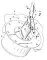
- a multi-function probe assembly indicated generally at 10 includes a strut 12 that is generally airfoil shaped in cross section as shown in Figures 4-6.
- the strut 12 is supported on a mounting plate 14.
- the mounting plate 14 in turn is adapted to be mounted in place on the skin of an aircraft 16.
- the multi-function probe strut 12 supports a multi-function sensing head assembly 18 at its outer end.
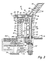
- This head assembly 18 includes a pitot pressure sensing tube 20 which has a forward pitot pressure sensing port 22, and as can be seen in Figures 2 and 3, the tube has an interior passageway 24 in which a suitable de-icing heater 25 is mounted.
- the base end of the pitot sensing pressure tube is open to a chamber 27, and a tube or line 26 opens to the pitot pressure chamber 27.
- the tube 26 passes through provided openings and across a chamber 28.
- the tube 26 is connected to a pitot pressure sensor 29 in an instrument or circuitry package indicated generally at 30 ( Figures 1 and 2).
- the sensor head assembly 18 is supported sufficiently outward from the aircraft skin 16, so it is outside a boundary layer of air on the skin, and is in substantially free stream conditions, insofar as airflow past the probe is concerned.
- the airflow direction is indicated by arrow 32.
- the pitot pressure sensing port 22 faces upstream.
- the sensor head 18 Adjacent to and below the pitot pressure sensing tube 22, the sensor head 18 has a duct 34 comprising a total air temperature sensor inlet scoop with a wide inlet scoop opening 36 facing upstream. It can be seen that this inlet scoop opening 36 is positioned outside the boundary layer of air on the aircraft skin.
- the duct 34 forms a curved flow path providing inertial separation of large particles from the air stream.
- the duct 34 is shaped to cause part of the air flow to turn substantially 90 degrees around a rounded surface of a wall portion 38.
- the wall portion 38 is provided with openings 37 to bleed off the boundary layer air into a cross channel 39 prior to where the flow enters a flow throat 40 that leads to chamber 28 in which a total air temperature sensor 44 is mounted.
- the boundary layer bleed air passing through openings 37 is discharged laterally through side openings that bleed or exhaust air from cross channel 39, as shown in Figures 1 and 2.
- the total air temperature sensor 44 is preferably a sealed platinum resistance element in an outer case 44A through which the air from throat 40 flows as shown in Figures 4 and 6.
- the outer case 44A for the total temperature sensor is tubular, as is an outer shield 44B, as shown in Figure 3.
- the outer case 44A and outer shield 44B have outlet openings 44C and 44D (see Figure 6) so the air flowing past the total air temperature discharges into chamber 28 and out a rear port 42, which is at a lower pressure region, such as at the rear of the strut. Any suitable known total air temperature sensor can be used.
- the temperature sensor 44 is connected to read out circuitry 45 in the instrument package 30.
- the curved wall 38, and the flow of part of the air into throat 40, results in inertial separation of larger particles, such as liquid particles, so that part of the air flow, and the larger particles, enter a discharge passageway 41 ( Figure 6) that open to a lower pressure region of the strut through one or more ports 41A.
- the air that enters passageway 41, as shown, discharges toward the rear and laterally of the sensing head 18.
- the ports 41A are positioned so the air being discharged does not affect other measurement or sensing functions of the probe.
- Static pressure sensing ports 50A and 50B are provided on the top and bottom walls of the strut 12
- the ports 50A and 50B open to passageways 51A and 51B in the strut ( Figures 5 and 6).
- the passageways 51A and 51B are connected to separate pressure sensors 53A and 53B in the instrument package 30 (see Figures 5 and 6), and static pressure will be sensed as the probe moves with the aircraft through an air stream.
- the pressure signal from each port 50A, 50B are individually provided as electrical signals, and the signals can be averaged, as well as subtracted, for calculation of angle of attack, if desired.
- a vane type angle of attack sensor 52 is provided.
- the ability to calculate angle of attack from pressure measurements provides redundancy of measurement, and can provide supplemental information.
- the sensor 52 includes a vane 54 mounted onto a hub 56, which in turn is attached to a shaft 58.
- the shaft 58 is mounted in suitable bearings 60, for free rotation about the shaft axis.
- the inner end of the shaft 58 extends into the instrument package 30 on an interior of the aircraft and is coupled to a conventional angle resolver 62 that senses the rotational movement of the vane 54 about the axis of the shaft 58 to determine changes in the vane angle relative to the strut 12 and aircraft.
- the changes in vane angle result from changes in the angle of attack of the air vehicle or aircraft 16.
- the strut 12 is fixed to the aircraft, and the shaft 58 rotates in the strut 12 as the relative angle of attack changes.
- the instrument package 30 includes the angle resolver 62 coupled to the shaft 58, and suitable readout circuitry, used on existing angle of attack vanes. This can be any desired type of angle resolver, such as that shown in the prior art, and known in the trade.
- the other circuit components making up the instrument package 30 comprise circuit boards of cards mounted on standoff posts 66, that are attached to the strut mounting plate 14.
- the pressure sensing condition circuitry can also be mounted on one or more of these circuit cards.
- circuit cards can be included, such as those shown at 72 for providing the necessary power supply, heater controls, and communication circuitry.
- the circuits connect through a single fitting 74 to an onboard computer 76, or, alternatively directly to aircraft controls 78.
- a processor 79 for computing and compensating outputs may be provided in the circuit package 30. In such case, processor 79 can replace or supplement the on-board computer 76.
- the instrument package 30 and probe assembly are removable and replaceable as a unit.
- the leading edge 80 of the strut 12 has a suitable de-icing heater, such as a conventional resistant wire heater 82, embedded therein. Because of the mounting of the probe assembly, and the size of the probe assembly, the overall power needed for de-icing the probe is reduced compared with the power needed to de-ice separate pitot, pitot-static and angle of attack probes.
- a bore 81 in the strut 12 can be used for mounting a cartridge heater, if desired to supplement or replace the wire heater 82.
- the angle of vane 54 can have solid state de-icing heaters installed therein, such as the positive temperature coefficient heaters 83 shown in Figure 3.
- the leading edge 80 of the strut is shown at substantially a right angle to the skin 16 of the aircraft, but it can be swept rearwardly slightly.
- the trailing edge also can be inclined, if desired.
- the shaft 58 has an axis of rotation that is preferably substantially perpendicular to the aircraft skin 16, and preferably perpendicular to the direction of air flow 32.
- the angular readout from the resolver 62 used with the vane type angle of attack sensor 52 provides a measurement of local angle of attack, which can be corrected by suitable algorithims, as is well known. Such correction can take place in the memory of processor 79 in instrument package 30, to provide actual angle of attack. Wind tunnel tests can be used for determining the correlation between the local angle of attack as measured, and the actual angle of attack, and provided in a lookup table in the memory of the processor 79 or computer 76, or both.
- the angle of attack that is measured by the vane (AOA m ) can be corrected to provide the true angle of attack of the probe (AOA p ) by providing constants that relate to the configuration of the aircraft and the probe on which the vane is mounted.
- angle of attack can be calculated by utilizing the pressures at the ports 51A and 51B, which pressures are individually sensed for providing separate electrical signals. The calculations are carried out in the well known manner that is used where static pressure sensing ports are provided on opposite sides of a cylindrical barrel type probe mounted on a strut.
- the correction or scaling factors to solve the equations can be provided by lookup tables in the processor 79.
- the necessary scaling factors can be provided by wind tunnel tests for the particular aircraft construction.
- the multi-function probe includes a total air temperature sensor design that provides accurate total air temperature measurements in a robust probe.
- the air flow path to chamber 28 provides water and particle droplets separation from the air flowing by the total temperature sensor.
- the positioning of the temperature sensor in the probe minimizes the de-icing power required, and this minimizes the heating error that may be introduced to total air temperature sensors.
- the probe assembly 10 is a stand alone probe design, and is easier to service and replace.
- the pitot tube is maintained in a known position relative to the air stream past the air craft, and it has the ability to accurately measure the pitot pressure.
- the shaft 58 for the angle of attack sensing vane 54 passes through a bore 90 ( Figure 3) that is larger in diameter than the shaft.
- This bore can be filled with a suitable damping fluid 91, such as a viscous oil, if desired.
- the viscous material will dampen flutter or oscillations of the vane.
- the pitot tube 20 remains oriented in a fixed position on the strut.
- the vane 54 can move without affecting the position of the pitot tube.
Abstract
Description
- The present invention relates to a multi-function probe for mounting on air vehicles which incorporates a plurality of air data sensors in one probe body, including a vane type angle of attack sensor to reduce the number of projecting struts and probes from an air vehicle surface, thereby saving weight, and reducing drag.
- In the past, multi-function probes that sense pressure parameters comprising static pressure, pitot pressure, and total temperature, have been advanced. These probes also included ports that were located so that angle of attack could be determined due to pressure differentials at the selected ports.
- U.S. Patent No. 5,731,507 discloses an air data sensing probe that senses pitot pressure, and static pressure, and include a total temperature sensor. The probe disclosed in this patent also has angle of attack pressure sensing ports that are located on a common plane on opposite sides of the probe. Angle of attack is determined by pressure differentials at such ports.
- Angle of attack sensors that have a vane mounted to pivot on a cylindrical probe about an axis generally perpendicular to the central axis of the probe are known. For example, U.S. Patent No. 3,882,721 illustrates such a vane type sensor mounted directly to the skin of an air vehicle.
- A total air temperature measurement probe using digital compensation circuitry is disclosed in U.S Patent No. 6,543,298, the disclosure of which is incorporated by reference.
- The present invention relates to an air data sensing probe assembly that includes a plurality of air data sensors integrated into a single, line replaceable probe unit. The probe has a low drag strut or support housing supported on an air vehicle surface and projecting laterally into the air stream. The strut supports a pitot pressure sensing tube or head, a total air temperature sensor with associated ducting in the strut, as well as static pressure sensing ports on the side surfaces of the probe. The strut further mounts a rotatable vane angle of attack sensor. Thus, pitot pressure (Pt), static pressure (Ps), total air temperature (TAT), and angle of attack (AOA) are all measured in a single unit.
- The probe assembly provides the benefits of a vane type angle of attack sensor, but does not require calculations based on sensed differential pressures, although, as disclosed, sensed differential pressures are available for redundancy. A rugged probe that will accurately sense pressures and also provide accurate and reliable angle of attack indications is provided.
- The sensors are arranged so there is little interference with the inlet scoop for the total temperature sensor passageways. Additionally, an air data computer is mounted directly to the mounting plate for the air data sensor probe assembly so that all sensors, signal conditioning circuits, and all calculations along with the necessary readout signals can be provided from a single package that can be easily removed and replaced for service. In other words, the multi-function probe is a smart probe that provides all needed air data information for high performance aircraft.
- On-board processors also can be used for the calculations, if desired.
-
- Figure 1 is a front perspective view of a multi-function probe made according to the present invention in place on a side of an air vehicle;
- Figure 2 is a sectional view of the multi-function probe taken along
line 2--2 in Figure 1; - Figure 3 is an enlarged sectional view of the probe assembly along
line 2--2 with parts removed and partially broken away; - Figure 4 is a sectional view taken on
line 4--4 in Figure 2; - Figure 5 is a sectional view taken on line 5--5 in Figure 2; and
- Figure 6 is a sectional view taken as on line 6--6 in Figure 2.
- A multi-function probe assembly indicated generally at 10 includes a
strut 12 that is generally airfoil shaped in cross section as shown in Figures 4-6. Thestrut 12 is supported on amounting plate 14. Themounting plate 14 in turn is adapted to be mounted in place on the skin of anaircraft 16. - The
multi-function probe strut 12 supports a multi-functionsensing head assembly 18 at its outer end. Thishead assembly 18 includes a pitotpressure sensing tube 20 which has a forward pitotpressure sensing port 22, and as can be seen in Figures 2 and 3, the tube has aninterior passageway 24 in which asuitable de-icing heater 25 is mounted. - The base end of the pitot sensing pressure tube is open to a
chamber 27, and a tube orline 26 opens to thepitot pressure chamber 27. Thetube 26 passes through provided openings and across achamber 28. Thetube 26 is connected to apitot pressure sensor 29 in an instrument or circuitry package indicated generally at 30 (Figures 1 and 2). - The
sensor head assembly 18 is supported sufficiently outward from theaircraft skin 16, so it is outside a boundary layer of air on the skin, and is in substantially free stream conditions, insofar as airflow past the probe is concerned. The airflow direction is indicated byarrow 32. The pitotpressure sensing port 22 faces upstream. - Adjacent to and below the pitot
pressure sensing tube 22, thesensor head 18 has aduct 34 comprising a total air temperature sensor inlet scoop with a wide inlet scoop opening 36 facing upstream. It can be seen that thisinlet scoop opening 36 is positioned outside the boundary layer of air on the aircraft skin. - The
duct 34 forms a curved flow path providing inertial separation of large particles from the air stream. Theduct 34 is shaped to cause part of the air flow to turn substantially 90 degrees around a rounded surface of awall portion 38. Thewall portion 38 is provided withopenings 37 to bleed off the boundary layer air into across channel 39 prior to where the flow enters a flow throat 40 that leads tochamber 28 in which a totalair temperature sensor 44 is mounted. The boundary layer bleed air passing throughopenings 37 is discharged laterally through side openings that bleed or exhaust air fromcross channel 39, as shown in Figures 1 and 2. - The total
air temperature sensor 44 is preferably a sealed platinum resistance element in anouter case 44A through which the air from throat 40 flows as shown in Figures 4 and 6. Theouter case 44A for the total temperature sensor is tubular, as is anouter shield 44B, as shown in Figure 3. Theouter case 44A andouter shield 44B haveoutlet openings 44C and 44D (see Figure 6) so the air flowing past the total air temperature discharges intochamber 28 and out arear port 42, which is at a lower pressure region, such as at the rear of the strut. Any suitable known total air temperature sensor can be used. Thetemperature sensor 44 is connected to read outcircuitry 45 in theinstrument package 30. - The
curved wall 38, and the flow of part of the air into throat 40, results in inertial separation of larger particles, such as liquid particles, so that part of the air flow, and the larger particles, enter a discharge passageway 41 (Figure 6) that open to a lower pressure region of the strut through one ormore ports 41A. The air that enterspassageway 41, as shown, discharges toward the rear and laterally of thesensing head 18. Theports 41A are positioned so the air being discharged does not affect other measurement or sensing functions of the probe. - Static
pressure sensing ports strut 12 Theports passageways passageways separate pressure sensors port - In order to provide a direct and primary measurement of angle of attack of an aircraft on which
probe 10 is mounted, a vane type angle ofattack sensor 52 is provided. The ability to calculate angle of attack from pressure measurements provides redundancy of measurement, and can provide supplemental information. - The
sensor 52 includes avane 54 mounted onto ahub 56, which in turn is attached to ashaft 58. Theshaft 58 is mounted insuitable bearings 60, for free rotation about the shaft axis. The inner end of theshaft 58 extends into theinstrument package 30 on an interior of the aircraft and is coupled to aconventional angle resolver 62 that senses the rotational movement of thevane 54 about the axis of theshaft 58 to determine changes in the vane angle relative to thestrut 12 and aircraft. The changes in vane angle result from changes in the angle of attack of the air vehicle oraircraft 16. Thestrut 12 is fixed to the aircraft, and theshaft 58 rotates in thestrut 12 as the relative angle of attack changes. - The
instrument package 30 includes theangle resolver 62 coupled to theshaft 58, and suitable readout circuitry, used on existing angle of attack vanes. This can be any desired type of angle resolver, such as that shown in the prior art, and known in the trade. - The other circuit components making up the
instrument package 30 comprise circuit boards of cards mounted on standoff posts 66, that are attached to thestrut mounting plate 14. A circuit card that has solid state pressure sensors forsensors resolver circuit card 70 for theresolver 62. The pressure sensing condition circuitry can also be mounted on one or more of these circuit cards. - Various other circuit cards can be included, such as those shown at 72 for providing the necessary power supply, heater controls, and communication circuitry. The circuits connect through a
single fitting 74 to an onboard computer 76, or, alternatively directly to aircraft controls 78. In addition, aprocessor 79 for computing and compensating outputs may be provided in thecircuit package 30. In such case,processor 79 can replace or supplement the on-board computer 76. Theinstrument package 30 and probe assembly are removable and replaceable as a unit. - The leading
edge 80 of thestrut 12 has a suitable de-icing heater, such as a conventionalresistant wire heater 82, embedded therein. Because of the mounting of the probe assembly, and the size of the probe assembly, the overall power needed for de-icing the probe is reduced compared with the power needed to de-ice separate pitot, pitot-static and angle of attack probes. A bore 81 in thestrut 12 can be used for mounting a cartridge heater, if desired to supplement or replace thewire heater 82. It should be noted that the angle ofvane 54 can have solid state de-icing heaters installed therein, such as the positivetemperature coefficient heaters 83 shown in Figure 3. - The leading
edge 80 of the strut is shown at substantially a right angle to theskin 16 of the aircraft, but it can be swept rearwardly slightly. The trailing edge also can be inclined, if desired. Theshaft 58 has an axis of rotation that is preferably substantially perpendicular to theaircraft skin 16, and preferably perpendicular to the direction ofair flow 32. - The angular readout from the
resolver 62 used with the vane type angle ofattack sensor 52 provides a measurement of local angle of attack, which can be corrected by suitable algorithims, as is well known. Such correction can take place in the memory ofprocessor 79 ininstrument package 30, to provide actual angle of attack. Wind tunnel tests can be used for determining the correlation between the local angle of attack as measured, and the actual angle of attack, and provided in a lookup table in the memory of theprocessor 79 or computer 76, or both. - The angle of attack that is measured by the vane (AOAm) can be corrected to provide the true angle of attack of the probe (AOAp) by providing constants that relate to the configuration of the aircraft and the probe on which the vane is mounted. The general equation is as follows:

- The measurements of pressures on the multi-function probe disclosed also provides for systematic corrections for pitot pressure (Pt); static pressure (Ps), and total air temperature (TAT). Equations can be expressed as follows:


- f indicates function of:
- Pt = total pressure
- Ptm = measured total pressure
- Ps = local static pressure
- Psm = measured static pressure
- AOAp = probe angle of attack (in degrees or radians)
- TAT = total air temperature
- TATm = measured total temperature
- AOAm = measured probe angle
- Additionally, angle of attack can be calculated by utilizing the pressures at the
ports ports port 51B as P1 andport 51A as P2, the differential pressure is expressed as:
- The angle of attack of the probe is expressed as:


- The correction or scaling factors to solve the equations can be provided by lookup tables in the
processor 79. The necessary scaling factors can be provided by wind tunnel tests for the particular aircraft construction. - Reference is made to U.S. Patent No. 6,543,298, which is incorporated by reference, for showing digital corrections for the measured total air temperature.
- The multi-function probe includes a total air temperature sensor design that provides accurate total air temperature measurements in a robust probe. The air flow path to
chamber 28 provides water and particle droplets separation from the air flowing by the total temperature sensor. The positioning of the temperature sensor in the probe minimizes the de-icing power required, and this minimizes the heating error that may be introduced to total air temperature sensors. The location of the scoop inlet opening for the total air temperature sensor, and the design of the flow passage, insures accurate performance. - The
probe assembly 10 is a stand alone probe design, and is easier to service and replace. The pitot tube is maintained in a known position relative to the air stream past the air craft, and it has the ability to accurately measure the pitot pressure. - The incorporation of a vane angle of attack sensor as part of the multi-function probe avoids possible port clogging problems that can occur where only pneumatic signals are used for calculating angle of attack, and provides for high reliability. Angle change dynamic response is also high since the vane is positioned at the outer end of the strut, outside of boundary layer air and other influences caused by the aircraft surface.
- The
shaft 58 for the angle ofattack sensing vane 54 passes through a bore 90 (Figure 3) that is larger in diameter than the shaft. This bore can be filled with a suitable dampingfluid 91, such as a viscous oil, if desired. The viscous material will dampen flutter or oscillations of the vane. - The
pitot tube 20 remains oriented in a fixed position on the strut. Thevane 54 can move without affecting the position of the pitot tube. - Although the present invention has been described with reference to preferred embodiments, workers skilled in the art will recognize that changes may be made in form and detail without departing from the scope of the invention.
Claims (14)
- A multi-function air data sensor probe for sensing a plurality of air data parameters comprising a pitot pressure sensing port at an outer end of said probe, a total air temperature sensor in said probe, at least one static pressure sensing port on said probe, and a rotatably mounted angle of attack sensing vane mounted on the probe for rotation about an axis operated to indicate relative air flow direction past the probe.
- The multi-function air data sensor probe of Claim 1, wherein said static pressure sensing port is positioned on a lateral side of the probe, and is in fluid communication with a passageway on the interior of the probe and a pressure sensor in fluid communication with the passageway for measuring the pressure in the passageway.
- The multi-function air data sensor probe of Claims 1 or 2, wherein the probe has a base end for mounting on an aircraft, and a self-contained instrumentation package mounted at the base end for installation as a unit with the probe onto an aircraft with the instrument package on an interior of such aircraft.
- The multi-function air data sensor probe of any preceding claim, wherein the probe comprises a strut that has a base end that mounts on the skin of an aircraft, the sensing vane being mounted on a shaft supported on the strut with the shaft rotation about the axis, and an angle resolver connected to the shaft for determining changes in angle of the shaft as air flow past the strut changes the relative position of the sensing vane.
- The multi-function air data sensor probe of any preceding claim, wherein the probe has a flow duct, the total air temperature sensor being mounted to be in fluid communication with the flow duct, an inlet to the flow duct comprising a forwardly facing air scoop, a wall surface defining portions of the scoop and flow duct and over which the air flows, and a plurality of openings in the wall surface to remove boundary layer air as the flow passes into the flow duct.
- The multi-function air data sensor probe of Claim 4 or Claim 5 when dependent thereon, wherein the strut has upper and lower lateral sides, the at least one static sensing port comprising a first static pressure sensing port on the upper lateral side of the struts, and a second static sensing port on the lower lateral side of the strut, and a separate pressure sensor coupled to the respective first and second static sensing ports.
- An aircraft comprising the multi-function air data sensor probe of any preceding claim.
- A multi-function air data sensing probe having a base end mountable to an aircraft to extend laterally outwardly therefrom, an angle of attack sensor vane mounted on said probe and positioned at an outer end thereof and extending outwardly therefrom, said vane being pivotable about an axis generally perpendicular to a surface of an aircraft on which the probe is mounted, a sensor to sense an angular position of the vane relative to a reference, an outer end of the said probe having a pitot port facing upstream relative to air flow past the strut, a forwardly facing total temperature sensor inlet scoop formed on the probe, and spaced from the pitot port, said scoop leading to a flow passageway that changes direction to direct flow into a first chamber, a total air temperature sensor in said first chamber, said first chamber having exhaust openings therefrom for permitting air to flow through said chamber, separate static pressure ports on side surfaces of the said probe between the base and the pivot port, and pressure sensors connected to separately sense pressures at the pitot port and the static pressure ports.
- The multi-function air data sensing probe of Claim 8, wherein said inlet scoop directs flow over a surface of a wall having a plurality of openings therethrough for bleeding boundary layer air through the openings to remove said boundary layer air prior to the flow entering the first chamber.
- The multi-function air data sensing probe of either of Claims 8 or 9, wherein said pitot port is at an end of a tube, said tube being mounted on an outer end of said strut and extending upstream beyond the inlet scoop for the total temperature sensor.
- The multi-function air data sensing probe of Claim 10, wherein probe includes a strut between the base on the tube having the pilot port, a generally airfoil shape cross section, and wherein the static pressure sensing ports are on upper and lower sides of the strut.
- The multi-function air data sensing probe of any one of Claims 8 to 11, further comprising a processor including lookup tables for compensation of measured angle of attack, pilot pressure, and static pressure to provide corrected angle of attack and pressure signals.
- The multi-function air data sensing probe of Claim 12, wherein the processor is mounted in an instrument housing directly attached to a mounting plate for the probe.
- An aircraft comprising the multi-function air data sensing probe of any of Claims 8 to 13.
Applications Claiming Priority (2)
| Application Number | Priority Date | Filing Date | Title |
|---|---|---|---|
| US606929 | 2003-06-26 | ||
| US10/606,929 US6941805B2 (en) | 2003-06-26 | 2003-06-26 | Multi-function air data sensing probe having an angle of attack vane |
Publications (3)
| Publication Number | Publication Date |
|---|---|
| EP1491900A2 true EP1491900A2 (en) | 2004-12-29 |
| EP1491900A3 EP1491900A3 (en) | 2005-02-23 |
| EP1491900B1 EP1491900B1 (en) | 2010-06-16 |
Family
ID=33418704
Family Applications (1)
| Application Number | Title | Priority Date | Filing Date |
|---|---|---|---|
| EP04253847A Active EP1491900B1 (en) | 2003-06-26 | 2004-06-28 | Multi-function air data sensing probe having an angle of attack vane |
Country Status (3)
| Country | Link |
|---|---|
| US (1) | US6941805B2 (en) |
| EP (1) | EP1491900B1 (en) |
| DE (1) | DE602004027683D1 (en) |
Cited By (13)
| Publication number | Priority date | Publication date | Assignee | Title |
|---|---|---|---|---|
| US7114847B2 (en) * | 2002-06-14 | 2006-10-03 | Thales | Total temperature probe and method of determining total temperature |
| WO2007024159A2 (en) | 2005-08-26 | 2007-03-01 | Federalnoe Gosudarstvennoe Unitarnoe Prepprijatie 'central Aerohydrodynamic Institute'(Fgup Tsagi) Named After Prof. N.E. Zhukovsky | Flight air data measuring system |
| WO2008077131A3 (en) * | 2006-12-19 | 2008-07-31 | Rosemount Aerospace Inc | Integrated total air temperature probe and electronics |
| FR2932456A1 (en) * | 2008-06-17 | 2009-12-18 | Airbus France | SYSTEM FOR DRAINING A LIGHTNING CURRENT GENERATED BY A STORM DISCHARGE ON AN AIRCRAFT |
| CN102723575A (en) * | 2012-05-25 | 2012-10-10 | 中国人民解放军海军航空工程学院 | Mounting and fixing method for additionally mounting remodeled antenna on airplane |
| EP3009847A1 (en) * | 2014-10-15 | 2016-04-20 | Rosemount Aerospace Inc. | One-piece air data probe |
| CN105966635A (en) * | 2016-05-25 | 2016-09-28 | 江西洪都航空工业集团有限责任公司 | Waterproof support compatible with mounting of various types of sensors |
| WO2016192977A1 (en) * | 2015-06-01 | 2016-12-08 | Robert Bosch Gmbh | Air heat pump for obtaining environmental heat from air |
| FR3047564A1 (en) * | 2016-02-09 | 2017-08-11 | Aer | ANEMOMETRIC SPEED MEASUREMENT PROBE OF AN AIRCRAFT |
| US10126208B2 (en) | 2015-10-22 | 2018-11-13 | Rolls-Royce Plc | Sensor system having a sensor supported by a mast for use within fluid flows |
| EP3546907A1 (en) * | 2018-03-30 | 2019-10-02 | Honeywell International Inc. | Self-regulating heating system for a total air temperature probe |
| EP3715860A1 (en) | 2019-03-25 | 2020-09-30 | Rosemount Aerospace Inc. | Digital air data systems and methods |
| CN113866451A (en) * | 2021-12-06 | 2021-12-31 | 大同航源众诚动力科技有限公司 | Civil aircraft airspeed head self-separation protective sleeve |
Families Citing this family (64)
| Publication number | Priority date | Publication date | Assignee | Title |
|---|---|---|---|---|
| FR2833709B1 (en) * | 2001-12-14 | 2004-04-02 | Thales Sa | VARIABLE BOOM MULTIFUNCTION PROBE |
| US7014357B2 (en) * | 2002-11-19 | 2006-03-21 | Rosemount Aerospace Inc. | Thermal icing conditions detector |
| US7156552B2 (en) * | 2004-09-07 | 2007-01-02 | University Corporation For Atmospheric Research | Temperature sensor system for mobile platforms |
| US7194920B2 (en) * | 2005-03-15 | 2007-03-27 | Welker Engineering Company | Sensor probe and pipeline construction and method |
| US7490510B2 (en) * | 2005-10-24 | 2009-02-17 | Ametek, Inc. | Multi-function air data sensor |
| US7597018B2 (en) * | 2007-04-11 | 2009-10-06 | Rosemount Aerospace Inc. | Pneumatic line isolation and heating for air data probes |
| US7828477B2 (en) * | 2007-05-14 | 2010-11-09 | Rosemount Aerospace Inc. | Aspirated enhanced total air temperature probe |
| US8761970B2 (en) * | 2008-10-21 | 2014-06-24 | The Boeing Company | Alternative method to determine the air mass state of an aircraft and to validate and augment the primary method |
| US8392141B2 (en) * | 2009-11-02 | 2013-03-05 | Rosemount Aerospace Inc. | Total air temperature probe and method for reducing de-icing/anti-icing heater error |
| ES2394558B1 (en) * | 2010-01-18 | 2013-12-12 | Eads Construcciones Aeronáuticas, S.A. | PROBE SUPPORT DEVICE. |
| US8365591B2 (en) * | 2010-11-15 | 2013-02-05 | Rosemount Aerospace Inc. | Static port apparatus |
| DE102011005355A1 (en) * | 2011-03-10 | 2012-09-13 | Airbus Operations Gmbh | Component assembly on an aircraft structure and method for installing a component in an aircraft structure |
| CN102288785A (en) * | 2011-07-08 | 2011-12-21 | 中国航空动力机械研究所 | Sensor for testing flow field direction |
| GB201112803D0 (en) * | 2011-07-26 | 2011-09-07 | Rolls Royce Plc | Master component for flow calibration |
| US8438915B2 (en) * | 2011-08-29 | 2013-05-14 | United Technologies Corporation | Insert assembly and method for fluid flow reverse engineering |
| US8517604B2 (en) * | 2011-12-21 | 2013-08-27 | Unison Industries, Llc | Apparatus for determining an air temperature |
| US9429481B2 (en) | 2012-08-31 | 2016-08-30 | Ametek, Inc. | Apparatus and method for measuring total air temperature within an airflow |
| US9829395B2 (en) * | 2012-12-13 | 2017-11-28 | Rosemount Aerospace Inc. | Air temperature sensor arrangement for a vehicle and method of measuring air temperature |
| FR3011082B1 (en) * | 2013-09-20 | 2015-10-16 | Thales Sa | AERODYNAMIC MEASUREMENT PROBE WITH GRAVITY INFILTRATION LIQUID EXHAUST |
| US9689755B2 (en) | 2013-10-22 | 2017-06-27 | Rosemount Aerospace Inc. | Temperature sensors |
| US9884685B2 (en) * | 2014-05-28 | 2018-02-06 | The Boeing Company | External case heater for an angle of attack sensor |
| USD747985S1 (en) * | 2014-07-22 | 2016-01-26 | Gulfstream Aerospace Corporation | Aircraft ice detector |
| US9702783B2 (en) | 2014-08-01 | 2017-07-11 | Rosemount Aerospace Inc. | Air data probe with fluid intrusion sensor |
| US10227139B2 (en) | 2015-03-23 | 2019-03-12 | Rosemount Aerospace Inc. | Heated air data probes |
| US11209330B2 (en) | 2015-03-23 | 2021-12-28 | Rosemount Aerospace Inc. | Corrosion resistant sleeve for an air data probe |
| GB2541356A (en) * | 2015-06-08 | 2017-02-22 | Meggitt (Uk) Ltd | Moving-vane angle of attack probe |
| FR3039511B1 (en) * | 2015-07-28 | 2017-09-08 | Thales Sa | HEATING FOR AERONAUTICAL AIRCRAFT EQUIPMENT |
| US9791304B2 (en) * | 2015-10-21 | 2017-10-17 | Honeywell International Inc. | Air data probe heater utilizing low melting point metal |
| US10737793B2 (en) * | 2015-12-02 | 2020-08-11 | The Boeing Company | Aircraft ice detection systems and methods |
| US9752905B2 (en) | 2015-12-15 | 2017-09-05 | General Electric Company | Fluid transport system including a flow measurement system and a purge system |
| US10048288B2 (en) | 2016-01-08 | 2018-08-14 | Rosemount Aerospace Inc. | Angle of attack vane with differential pressure validation |
| US10048103B2 (en) * | 2016-09-23 | 2018-08-14 | Bell Helicopter Textron Inc. | Adjustable position pitot probe mount |
| CN106918410B (en) * | 2017-03-29 | 2020-11-17 | 北京航空航天大学 | Total temperature leaf type probe |
| US10585007B2 (en) * | 2017-06-22 | 2020-03-10 | Unison Industries, Llc | Air temperature sensor |
| US10605675B2 (en) | 2017-06-22 | 2020-03-31 | Unison Industries, Llc | Air temperature sensor |
| US10578498B2 (en) | 2017-06-22 | 2020-03-03 | Unison Industries, Llc | Air temperature sensor |
| US10545057B2 (en) | 2017-06-22 | 2020-01-28 | Unison Industries, Llc | Air temperature sensor and method of reducing error |
| USD844466S1 (en) | 2017-06-22 | 2019-04-02 | Unison Industries, Llc | Temperature sensor |
| KR101877424B1 (en) | 2017-08-01 | 2018-08-09 | 한국항공우주연구원 | Atmospheric information measuring apparatus for multi-copter using inertial sensor |
| US10393766B2 (en) | 2017-08-17 | 2019-08-27 | Rosemount Aerospace Inc. | Water management system for angle of attack sensors |
| US11181545B2 (en) * | 2017-08-17 | 2021-11-23 | Rosemount Aerospace Inc. | Angle of attack sensor with thermal enhancement |
| US10730637B2 (en) * | 2017-09-29 | 2020-08-04 | Rosemount Aerospace Inc. | Integral vane base angle of attack sensor |
| EP3749577B1 (en) * | 2018-02-07 | 2023-04-05 | Aerosonic LLC | Aircraft airflow sensor probe and process of implementing an aircraft sensor probe |
| US10948511B2 (en) * | 2018-03-05 | 2021-03-16 | Honeywell International Inc. | Apparatus and method for verifying operation of air data probes |
| US11414195B2 (en) | 2018-03-23 | 2022-08-16 | Rosemount Aerospace Inc. | Surface modified heater assembly |
| US10716171B2 (en) | 2018-03-23 | 2020-07-14 | Rosemount Aerospace Inc. | Power efficient heater control of air data sensor |
| US11022194B2 (en) | 2018-05-18 | 2021-06-01 | Rosemount Aerospace Inc. | Adjustable damper in angle of attack sensors |
| US10823751B2 (en) * | 2018-08-17 | 2020-11-03 | Rosemount Aerospace Inc. | Aircraft probe with removable and replaceable embedded electronics |
| US11002754B2 (en) | 2018-11-06 | 2021-05-11 | Rosemount Aerospace Inc. | Pitot probe with mandrel and pressure swaged outer shell |
| US10884014B2 (en) | 2019-03-25 | 2021-01-05 | Rosemount Aerospace Inc. | Air data probe with fully-encapsulated heater |
| US11428707B2 (en) | 2019-06-14 | 2022-08-30 | Rosemount Aerospace Inc. | Air data probe with weld sealed insert |
| US11162970B2 (en) | 2019-06-17 | 2021-11-02 | Rosemount Aerospace Inc. | Angle of attack sensor |
| EP4021809A4 (en) * | 2019-08-30 | 2023-07-26 | Aerosonic LLC | Aircraft airflow sensor having error correction based on aircraft movement and process of correcting said sensor based on aircraft movement |
| US11215631B2 (en) | 2019-10-16 | 2022-01-04 | Honeywell International Inc. | Multi-function air data probe having multi-hole ports used for determining angle of attack, total and static pressure values |
| US11814181B2 (en) | 2019-12-11 | 2023-11-14 | Rosemount Aerospace Inc. | Conformal thin film heaters for angle of attack sensors |
| US11649057B2 (en) | 2019-12-13 | 2023-05-16 | Rosemount Aerospace Inc. | Static plate heating arrangement |
| EP4111211A4 (en) * | 2020-02-25 | 2024-03-13 | Rosemount Aerospace Inc | Angle of attack sensor vane geometry |
| US11649056B2 (en) * | 2020-06-17 | 2023-05-16 | Honeywell International Inc. | Thermally isolated sensor for gas turbine engine |
| US11802888B2 (en) | 2020-09-21 | 2023-10-31 | Rosemount Aerospace Inc. | Damage detection for rotary angle measurement sensors |
| US11549914B2 (en) * | 2020-12-21 | 2023-01-10 | Hamilton Sundstrand Corporation | Surface acoustic wave sensors for air data probes |
| US11577853B2 (en) | 2021-04-13 | 2023-02-14 | William M. Fisher | Aircraft angle of attack and sideslip angle indicator |
| US11579163B1 (en) * | 2021-07-29 | 2023-02-14 | Rockwell Collins, Inc. | Differential pressure angle of attack sensor |
| US11624637B1 (en) | 2021-10-01 | 2023-04-11 | Rosemount Aerospace Inc | Air data probe with integrated heater bore and features |
| US11662235B2 (en) | 2021-10-01 | 2023-05-30 | Rosemount Aerospace Inc. | Air data probe with enhanced conduction integrated heater bore and features |
Citations (8)
| Publication number | Priority date | Publication date | Assignee | Title |
|---|---|---|---|---|
| US2850896A (en) * | 1954-11-29 | 1958-09-09 | Northrop Aircraft Inc | Airstream direction detector |
| US3665760A (en) * | 1969-12-15 | 1972-05-30 | Ferranti Ltd | Airflow direction indicators |
| US5423209A (en) * | 1992-04-06 | 1995-06-13 | National Aerospace Laboratory Of Science And Technology Agency | Truncated pyramid-shape multi-hole pitot probe and flight velocity detection system using said truncated pyramid-shape multi-hole pitot probe |
| US5731507A (en) * | 1993-09-17 | 1998-03-24 | Rosemount Aerospace, Inc. | Integral airfoil total temperature sensor |
| WO1999061924A1 (en) * | 1998-05-26 | 1999-12-02 | Professor N.E. Zhukovsky Central Aerohydrodynamic Institute | Pitot-static tube |
| US6419186B1 (en) * | 2000-03-31 | 2002-07-16 | Rosemount Aerospace Inc. | Standoff mounting for air data sensing probes on a helicopter |
| US6490510B1 (en) * | 1999-04-30 | 2002-12-03 | Thales Avionics S.A. | Fixed multifunction probe for aircraft |
| US20030051546A1 (en) * | 1999-12-17 | 2003-03-20 | Lionel Collot | Aircraft probe |
Family Cites Families (17)
| Publication number | Priority date | Publication date | Assignee | Title |
|---|---|---|---|---|
| US3882721A (en) * | 1973-11-16 | 1975-05-13 | Rosemount Inc | Vane type airflow sensor |
| US4458137A (en) * | 1981-04-09 | 1984-07-03 | Rosemount Inc. | Electric heater arrangement for fluid flow stream sensors |
| FR2569848B1 (en) * | 1984-09-03 | 1986-09-05 | Crouzet Badin Sa | AIRCRAFT PUR MULTIFUNCTION PRESSURE SENSOR |
| US5025661A (en) * | 1989-12-11 | 1991-06-25 | Allied-Signal Inc. | Combination air data probe |
| US5319970A (en) * | 1991-03-22 | 1994-06-14 | Rosemount, Inc. | Continuously curved strut mounted sensor |
| US5466067A (en) * | 1993-09-17 | 1995-11-14 | The B. F. Goodrich Company | Multifunctional air data sensing probes |
| US5601254A (en) * | 1994-10-28 | 1997-02-11 | Rosemount Aerospace Inc. | Single sided backbone strut for air data sensor |
| US5543183A (en) * | 1995-02-17 | 1996-08-06 | General Atomics | Chromium surface treatment of nickel-based substrates |
| US5653538A (en) * | 1995-06-07 | 1997-08-05 | Rosemount Aerospace Inc. | Total temperature probe |
| US5616861A (en) * | 1995-06-07 | 1997-04-01 | Rosemount Aerospace Inc. | Three pressure pseudo -Δ-P sensor for use with three pressure air data probe |
| US6370450B1 (en) * | 1999-12-10 | 2002-04-09 | Rosemount Aerospace Inc. | Integrated total temperature probe system |
| AU2001239948A1 (en) | 2000-03-09 | 2001-09-17 | Rosemount Aerospace Inc. | Integrated probe and sensor system |
| AU2001251302A1 (en) | 2000-04-05 | 2001-10-23 | Rosemount Aerospace Inc. | Magnetic angle of attack sensor |
| US6452542B1 (en) * | 2001-03-02 | 2002-09-17 | Rosemount Aerospace Inc. | Integrated flight management system |
| US6609421B2 (en) * | 2001-05-08 | 2003-08-26 | Rosemount Aerospace Inc. | Sideslip correction for a multi-function three probe air data system |
| US6543298B2 (en) * | 2001-07-13 | 2003-04-08 | Rosemount Aerospace Inc. | Method of reducing total temperature errors and multi-function probe implementing same |
| US6612166B2 (en) * | 2001-12-13 | 2003-09-02 | Rosemount Aerospace Inc. | Variable viscosity damper for vane type angle of attack sensor |
-
2003
- 2003-06-26 US US10/606,929 patent/US6941805B2/en not_active Expired - Lifetime
-
2004
- 2004-06-28 EP EP04253847A patent/EP1491900B1/en active Active
- 2004-06-28 DE DE602004027683T patent/DE602004027683D1/en active Active
Patent Citations (8)
| Publication number | Priority date | Publication date | Assignee | Title |
|---|---|---|---|---|
| US2850896A (en) * | 1954-11-29 | 1958-09-09 | Northrop Aircraft Inc | Airstream direction detector |
| US3665760A (en) * | 1969-12-15 | 1972-05-30 | Ferranti Ltd | Airflow direction indicators |
| US5423209A (en) * | 1992-04-06 | 1995-06-13 | National Aerospace Laboratory Of Science And Technology Agency | Truncated pyramid-shape multi-hole pitot probe and flight velocity detection system using said truncated pyramid-shape multi-hole pitot probe |
| US5731507A (en) * | 1993-09-17 | 1998-03-24 | Rosemount Aerospace, Inc. | Integral airfoil total temperature sensor |
| WO1999061924A1 (en) * | 1998-05-26 | 1999-12-02 | Professor N.E. Zhukovsky Central Aerohydrodynamic Institute | Pitot-static tube |
| US6490510B1 (en) * | 1999-04-30 | 2002-12-03 | Thales Avionics S.A. | Fixed multifunction probe for aircraft |
| US20030051546A1 (en) * | 1999-12-17 | 2003-03-20 | Lionel Collot | Aircraft probe |
| US6419186B1 (en) * | 2000-03-31 | 2002-07-16 | Rosemount Aerospace Inc. | Standoff mounting for air data sensing probes on a helicopter |
Cited By (22)
| Publication number | Priority date | Publication date | Assignee | Title |
|---|---|---|---|---|
| US7114847B2 (en) * | 2002-06-14 | 2006-10-03 | Thales | Total temperature probe and method of determining total temperature |
| WO2007024159A2 (en) | 2005-08-26 | 2007-03-01 | Federalnoe Gosudarstvennoe Unitarnoe Prepprijatie 'central Aerohydrodynamic Institute'(Fgup Tsagi) Named After Prof. N.E. Zhukovsky | Flight air data measuring system |
| EP1918686A2 (en) * | 2005-08-26 | 2008-05-07 | Federalnoe Gosudarstvennoe Unitarnoe Predprijatie | Flight air data measuring system |
| EP1918686A4 (en) * | 2005-08-26 | 2009-11-04 | Federalnoe Gup | Flight air data measuring system |
| WO2008077131A3 (en) * | 2006-12-19 | 2008-07-31 | Rosemount Aerospace Inc | Integrated total air temperature probe and electronics |
| US7854548B2 (en) | 2006-12-19 | 2010-12-21 | Rosemount Aerospace Inc. | Integrated total air temperature probe and electronics |
| US8699203B2 (en) | 2008-06-17 | 2014-04-15 | Airbus Operations S.A.S. | System for dissipating a lightning current generated by a thunderstorm discharge on an aircraft |
| FR2932456A1 (en) * | 2008-06-17 | 2009-12-18 | Airbus France | SYSTEM FOR DRAINING A LIGHTNING CURRENT GENERATED BY A STORM DISCHARGE ON AN AIRCRAFT |
| WO2009153452A2 (en) * | 2008-06-17 | 2009-12-23 | Airbus France | System for dissipating a lightning current generated by a thunderstorm discharge on an aircraft |
| WO2009153452A3 (en) * | 2008-06-17 | 2010-02-25 | AlRBUS OPERATIONS (société par actions simplifiée) | System for dissipating a lightning current generated by a thunderstorm discharge on an aircraft |
| CN102099249A (en) * | 2008-06-17 | 2011-06-15 | 空中客车营运有限公司 | System for dissipating a lightning current generated by a thunderstorm discharge on an aircraft |
| CN102099249B (en) * | 2008-06-17 | 2013-09-11 | 空中客车营运有限公司 | System for dissipating a lightning current generated by a thunderstorm discharge on an aircraft |
| CN102723575A (en) * | 2012-05-25 | 2012-10-10 | 中国人民解放军海军航空工程学院 | Mounting and fixing method for additionally mounting remodeled antenna on airplane |
| EP3009847A1 (en) * | 2014-10-15 | 2016-04-20 | Rosemount Aerospace Inc. | One-piece air data probe |
| WO2016192977A1 (en) * | 2015-06-01 | 2016-12-08 | Robert Bosch Gmbh | Air heat pump for obtaining environmental heat from air |
| US10126208B2 (en) | 2015-10-22 | 2018-11-13 | Rolls-Royce Plc | Sensor system having a sensor supported by a mast for use within fluid flows |
| FR3047564A1 (en) * | 2016-02-09 | 2017-08-11 | Aer | ANEMOMETRIC SPEED MEASUREMENT PROBE OF AN AIRCRAFT |
| CN105966635A (en) * | 2016-05-25 | 2016-09-28 | 江西洪都航空工业集团有限责任公司 | Waterproof support compatible with mounting of various types of sensors |
| EP3546907A1 (en) * | 2018-03-30 | 2019-10-02 | Honeywell International Inc. | Self-regulating heating system for a total air temperature probe |
| US11105691B2 (en) | 2018-03-30 | 2021-08-31 | Honeywell International Inc. | Self-regulating heating system for a total air temperature probe |
| EP3715860A1 (en) | 2019-03-25 | 2020-09-30 | Rosemount Aerospace Inc. | Digital air data systems and methods |
| CN113866451A (en) * | 2021-12-06 | 2021-12-31 | 大同航源众诚动力科技有限公司 | Civil aircraft airspeed head self-separation protective sleeve |
Also Published As
| Publication number | Publication date |
|---|---|
| US20040261518A1 (en) | 2004-12-30 |
| EP1491900A3 (en) | 2005-02-23 |
| EP1491900B1 (en) | 2010-06-16 |
| US6941805B2 (en) | 2005-09-13 |
| DE602004027683D1 (en) | 2010-07-29 |
Similar Documents
| Publication | Publication Date | Title |
|---|---|---|
| US6941805B2 (en) | Multi-function air data sensing probe having an angle of attack vane | |
| US7014357B2 (en) | Thermal icing conditions detector | |
| EP1948330B1 (en) | Multi-function air data sensor | |
| JP4422907B2 (en) | Air temperature sensor integrated probe for aircraft | |
| EP1256812B1 (en) | Sideslip correction for a multi-function three probe air data system | |
| EP1586877B1 (en) | Temperature sensor with controlled thermal offset for determining static temperature | |
| US6490510B1 (en) | Fixed multifunction probe for aircraft | |
| EP3104179B1 (en) | Moving-vane angle of attack probe | |
| US7150560B2 (en) | Device and method for determining total temperature for aircraft | |
| EP1602905B1 (en) | Sensor assembly for determining total temperature, static temperature and mach number | |
| CZ290912B6 (en) | Pitot-static tube | |
| US6452542B1 (en) | Integrated flight management system | |
| US10564173B2 (en) | Pitot-static probe with pneumatic angle-of-attack sensor | |
| US20120298801A1 (en) | Aircraft wing and sensor | |
| US6915687B2 (en) | Aerodynamically shaped static pressure sensing probe | |
| EP2527845A1 (en) | Aircraft wing and sensor | |
| EP2527847A1 (en) | Aircraft wing and sensor |
Legal Events
| Date | Code | Title | Description |
|---|---|---|---|
| PUAI | Public reference made under article 153(3) epc to a published international application that has entered the european phase |
Free format text: ORIGINAL CODE: 0009012 |
|
| AK | Designated contracting states |
Kind code of ref document: A2 Designated state(s): AT BE BG CH CY CZ DE DK EE ES FI FR GB GR HU IE IT LI LU MC NL PL PT RO SE SI SK TR |
|
| AX | Request for extension of the european patent |
Extension state: AL HR LT LV MK |
|
| PUAL | Search report despatched |
Free format text: ORIGINAL CODE: 0009013 |
|
| AK | Designated contracting states |
Kind code of ref document: A3 Designated state(s): AT BE BG CH CY CZ DE DK EE ES FI FR GB GR HU IE IT LI LU MC NL PL PT RO SE SI SK TR |
|
| AX | Request for extension of the european patent |
Extension state: AL HR LT LV MK |
|
| 17P | Request for examination filed |
Effective date: 20050414 |
|
| AKX | Designation fees paid |
Designated state(s): DE FR GB |
|
| 17Q | First examination report despatched |
Effective date: 20080225 |
|
| GRAP | Despatch of communication of intention to grant a patent |
Free format text: ORIGINAL CODE: EPIDOSNIGR1 |
|
| GRAS | Grant fee paid |
Free format text: ORIGINAL CODE: EPIDOSNIGR3 |
|
| GRAA | (expected) grant |
Free format text: ORIGINAL CODE: 0009210 |
|
| AK | Designated contracting states |
Kind code of ref document: B1 Designated state(s): DE FR GB |
|
| REF | Corresponds to: |
Ref document number: 602004027683 Country of ref document: DE Date of ref document: 20100729 Kind code of ref document: P |
|
| PLBE | No opposition filed within time limit |
Free format text: ORIGINAL CODE: 0009261 |
|
| STAA | Information on the status of an ep patent application or granted ep patent |
Free format text: STATUS: NO OPPOSITION FILED WITHIN TIME LIMIT |
|
| 26N | No opposition filed |
Effective date: 20110317 |
|
| REG | Reference to a national code |
Ref country code: DE Ref legal event code: R097 Ref document number: 602004027683 Country of ref document: DE Effective date: 20110316 |
|
| REG | Reference to a national code |
Ref country code: FR Ref legal event code: PLFP Year of fee payment: 13 |
|
| REG | Reference to a national code |
Ref country code: FR Ref legal event code: PLFP Year of fee payment: 14 |
|
| REG | Reference to a national code |
Ref country code: FR Ref legal event code: PLFP Year of fee payment: 15 |
|
| PGFP | Annual fee paid to national office [announced via postgrant information from national office to epo] |
Ref country code: FR Payment date: 20230523 Year of fee payment: 20 Ref country code: DE Payment date: 20230523 Year of fee payment: 20 |
|
| PGFP | Annual fee paid to national office [announced via postgrant information from national office to epo] |
Ref country code: GB Payment date: 20230523 Year of fee payment: 20 |