EP1491869A1 - Component temperature measuring method - Google Patents
Component temperature measuring method Download PDFInfo
- Publication number
- EP1491869A1 EP1491869A1 EP20040253128 EP04253128A EP1491869A1 EP 1491869 A1 EP1491869 A1 EP 1491869A1 EP 20040253128 EP20040253128 EP 20040253128 EP 04253128 A EP04253128 A EP 04253128A EP 1491869 A1 EP1491869 A1 EP 1491869A1
- Authority
- EP
- European Patent Office
- Prior art keywords
- component
- radiation
- coating
- blade
- emissivity
- Prior art date
- Legal status (The legal status is an assumption and is not a legal conclusion. Google has not performed a legal analysis and makes no representation as to the accuracy of the status listed.)
- Withdrawn
Links
- 238000000034 method Methods 0.000 title claims abstract description 20
- 230000005855 radiation Effects 0.000 claims abstract description 56
- 238000000576 coating method Methods 0.000 claims abstract description 47
- 239000011248 coating agent Substances 0.000 claims abstract description 36
- 238000005259 measurement Methods 0.000 claims abstract description 8
- 238000012545 processing Methods 0.000 claims description 4
- 238000005229 chemical vapour deposition Methods 0.000 claims description 3
- 238000003913 materials processing Methods 0.000 claims description 3
- 238000002488 metal-organic chemical vapour deposition Methods 0.000 claims description 3
- 238000001451 molecular beam epitaxy Methods 0.000 claims description 3
- 238000005240 physical vapour deposition Methods 0.000 claims description 3
- 230000035939 shock Effects 0.000 claims description 3
- 238000012360 testing method Methods 0.000 claims description 3
- 238000009529 body temperature measurement Methods 0.000 description 6
- 238000002485 combustion reaction Methods 0.000 description 3
- 230000001141 propulsive effect Effects 0.000 description 3
- 230000003287 optical effect Effects 0.000 description 2
- 230000003595 spectral effect Effects 0.000 description 2
- 238000004616 Pyrometry Methods 0.000 description 1
- 238000004164 analytical calibration Methods 0.000 description 1
- 230000006835 compression Effects 0.000 description 1
- 238000007906 compression Methods 0.000 description 1
- 238000013461 design Methods 0.000 description 1
- 239000000446 fuel Substances 0.000 description 1
- 238000013507 mapping Methods 0.000 description 1
- 239000000203 mixture Substances 0.000 description 1
- 238000002310 reflectometry Methods 0.000 description 1
- 238000001931 thermography Methods 0.000 description 1
- 238000011144 upstream manufacturing Methods 0.000 description 1
Images


Classifications
-
- G—PHYSICS
- G01—MEASURING; TESTING
- G01J—MEASUREMENT OF INTENSITY, VELOCITY, SPECTRAL CONTENT, POLARISATION, PHASE OR PULSE CHARACTERISTICS OF INFRARED, VISIBLE OR ULTRAVIOLET LIGHT; COLORIMETRY; RADIATION PYROMETRY
- G01J5/00—Radiation pyrometry, e.g. infrared or optical thermometry
- G01J5/02—Constructional details
- G01J5/06—Arrangements for eliminating effects of disturbing radiation; Arrangements for compensating changes in sensitivity
-
- G—PHYSICS
- G01—MEASURING; TESTING
- G01J—MEASUREMENT OF INTENSITY, VELOCITY, SPECTRAL CONTENT, POLARISATION, PHASE OR PULSE CHARACTERISTICS OF INFRARED, VISIBLE OR ULTRAVIOLET LIGHT; COLORIMETRY; RADIATION PYROMETRY
- G01J5/00—Radiation pyrometry, e.g. infrared or optical thermometry
- G01J5/0022—Radiation pyrometry, e.g. infrared or optical thermometry for sensing the radiation of moving bodies
Definitions
- the present invention relates to radiative temperature measurement.
- Radiative temperature measurement methods used in many industries take such forms as radiation pyrometry and thermal imaging.
- a frequent problem with radiative temperature measurements is the background radiation from another object.
- up to 70% of the measured radiation can be due to reflections from the combustor and surrounding hardware, leading to errors of up to 150°C.
- US5,125,739 discloses an optical pyrometer that uses three spectral bands for a temperature calculation of a target, such as a turbine blade of a gas turbine engine, whose output signal is compensated for spurious radiation reflected by the target from another single source, such as a combustor flame.
- the target temperature is optically distinguished from background radiation by dividing a received optical beam into three spectral components comprising emitted and reflected radiation.
- a controller computes the measured power in each band as a function of the emitted power by the target and a ratio of reflected power in adjacent bands to give signals of reflection corrected radiation. These are used with the reflected power ratios to determine values of temperature in adjacent bands.
- the difference between these computed temperatures is iteratively adjusted until the difference therebetween is approximately equal to a preselected value.
- this method is limited to where there is a single source of background radiation. In a gas turbine engine, for example, there are multiple sources of reflected radiation at multiple temperatures from surrounding architecture and this method is therefore not capable of distinguishing the true temperature of the object being measured.
- the present invention provides a solution to this problem for the general case of any number of reflection sources each with an unknown temperature.
- it is an object of the present invention to provide a method of measuring temperature of a component capable of emitting thermal radiation and reflecting background radiation comprising the steps of: providing a pyrometer for measuring the radiation from the component, characterised by coating a part of the component with a first emissivity coating and a part of the component with a different and second emissivity coating, each with known emissivities E H and E L respectively, recording a first radiation measurement from the first emissivity coating R H and a second radiation measurement from the second emissivity coating R L , then calculating the true radiation R Blade from the component from the equation and relate the R Blade value to the true component temperature by calibration of the pyrometer.
- a pyrometer or equivalent instrument will measure the sum of radiation emitted from a component due to its temperature plus ambient background radiation reflected from the component surface.
- the contribution to the measured radiation value due to the component temperature is proportional to its surface emissivity.
- the contribution to the measured radiation value due to ambient background radiation reflected from the component surface is proportional to its reflectivity, which is equal to (1-emissivity). Coatings of differing emissivities therefore introduce differing proportions of emitted and reflected radiation into the measurement. Where these emissivities are known, then the individual contributions from these two sources may be separated and the true component temperature calculated.
- the coatings of different emissivities are coated on an isotherm of the component and the pyrometer measures the radiation on the isotherm.
- a further coating of different emissivity from either coating is coated on the component for a further calculation of the true radiation R Blade .
- the component is a component of a gas turbine engine.
- the component is a component of any one of the group comprising a furnace, a kiln, an incinerator or a machine bearing.
- the component is a component of a process of any one of the group comprising rapid thermal processing, molecular beam epitaxy, chemical vapour deposition, metal organic chemical vapour deposition, physical vapour deposition, materials processing or thermal shock testing.
- a ducted fan gas turbine engine generally indicated at 10 has a principal and rotational axis 24.
- the engine 10 comprises, in axial flow series, an air intake 11, a propulsive fan 12, an intermediate pressure compressor 13, a high-pressure compressor 14, combustion equipment 15, a high-pressure turbine 16, and intermediate pressure turbine 17, a low-pressure turbine 18 and an exhaust nozzle 19.
- the gas turbine engine 10 works in the conventional manner so that air entering the intake 11 is accelerated by the fan to produce two air flows: a first air flow into the intermediate pressure compressor 13 and a second air flow which provides propulsive thrust.
- the intermediate pressure compressor 13 compresses the air flow directed into it before delivering that air to the high pressure compressor 14 where further compression takes place.
- the compressed air exhausted from the high-pressure compressor 14 is directed into the combustion equipment 15 where it is mixed with fuel and the mixture combusted.
- the resultant hot combustion products then expand through, and thereby drive the high, intermediate and low-pressure turbines 16, 17 and 18 before being exhausted through the nozzle 19 to provide additional propulsive thrust.
- the high, intermediate and low-pressure turbines 16, 17 and 18 respectively drive the high and intermediate pressure compressors 14 and 13 and the fan 12 by suitable interconnecting shafts.
- the fan 12 is circumferentially surrounded by a structural member in the form of a fan casing 30, which is supported by an annular array of outlet guide vanes 31.
- the high pressure turbine 16 comprises an annular array of radially extending turbine blades 26.
- Each blade 26 is conventional in both configuration and operation, having an aerofoil portion 28 supported on a platform 32 and attached to a disc 34 by dovetail joint 36.
- the radially outer portion of the blade 26 supports a shroud 38 provided to minimise gas leakage around the turbine stage.
- the turbine 16 is immediately downstream of the combustor 15 although it is common for an annular array of outlet guide vanes to be disposed therebetween.
- the present invention is also applicable to temperature measurements on any stage in the IP and LP turbines 17 and 18.
- a radiation pyrometer 40 is installed to view the upstream (or downstream) surface of the turbine stage 16 and is connected to processing equipment (not shown).
- a suitable radiation pyrometer 40 is a Rotamap 1 or 2 scanning pyrometer as manufactured by Rotadata Ltd, Derby, UK.
- the blade 26 achieves a stable temperature, and emits thermal radiation in accordance with the Planck equation.
- the blade 26 also reflects spurious radiation originating from the combustor 15 and other surrounding engine components.
- the two coatings have different emissivities there will therefore be differing amounts of thermal radiation from the component and reflected radiation from each coating type.
- the emissivities are known the blade radiation and reflected radiation are separable and a measurement of the component temperature is then calculable.
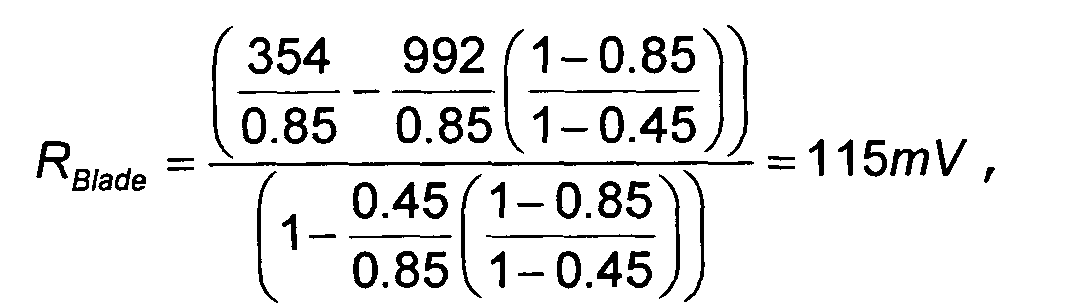
- the pyrometer may return a signal of 354mV from the high emissivity coating (corresponding to an erroneous uncorrected temperature of 1150°C) and a signal of 992mV from the low emissivity coating.
- the true signal due to the blade emission is therefore: which corresponds via the instrument calibration to the true blade temperature of 1000°C.
- a method of measuring temperature of a component 26 capable of emitting thermal Planck radiation and reflecting background radiation comprises the steps of providing a pyrometer 40 for measuring the radiation from the component 26, characterised by coating a part of the component 26 with a high emissivity coating 42 and a part of the component 26 with a low emissivity coating 44, each with known emissivities E H and E L respectively, recording a first temperature measurement from the high emissivity coating 42 R H and a second temperature measurement from the low emissivity coating 44 R L , then calculating the radiation R Blade of the component 26 from the above equation to find the corresponding component temperature using the calibration of the pyrometer.
- the high and low emissivity coatings 42, 44 are coated onto separate blades 26 or other components to be temperature measured.
- the method should comprise the coatings 42, 44 of different emissivities being coated on an isotherm 46 of the component 26. This is important so that the pyrometer 40 measures the radiation from the two coatings, on the isotherm 46, that are subject to the same true temperature.
- the method of the present invention is equally applicable to measuring the temperature of a component where the component is any one of the group comprising a furnace, a kiln, an incinerator or a machine bearing.
- the component is an element of a process of any one of the group comprising rapid thermal processing, molecular beam epitaxy, chemical vapour deposition, metal organic chemical vapour deposition, physical vapour deposition, materials processing or thermal shock testing.
Landscapes
- Physics & Mathematics (AREA)
- General Physics & Mathematics (AREA)
- Spectroscopy & Molecular Physics (AREA)
- Radiation Pyrometers (AREA)
Abstract

Description
- The present invention relates to radiative temperature measurement.
- Radiative temperature measurement methods used in many industries take such forms as radiation pyrometry and thermal imaging. A frequent problem with radiative temperature measurements is the background radiation from another object. For example, when measuring the temperature of a first stage turbine rotor of a gas turbine engine, up to 70% of the measured radiation can be due to reflections from the combustor and surrounding hardware, leading to errors of up to 150°C.
- US5,125,739 discloses an optical pyrometer that uses three spectral bands for a temperature calculation of a target, such as a turbine blade of a gas turbine engine, whose output signal is compensated for spurious radiation reflected by the target from another single source, such as a combustor flame. The target temperature is optically distinguished from background radiation by dividing a received optical beam into three spectral components comprising emitted and reflected radiation. A controller computes the measured power in each band as a function of the emitted power by the target and a ratio of reflected power in adjacent bands to give signals of reflection corrected radiation. These are used with the reflected power ratios to determine values of temperature in adjacent bands. The difference between these computed temperatures is iteratively adjusted until the difference therebetween is approximately equal to a preselected value. However, this method is limited to where there is a single source of background radiation. In a gas turbine engine, for example, there are multiple sources of reflected radiation at multiple temperatures from surrounding architecture and this method is therefore not capable of distinguishing the true temperature of the object being measured.
- The present invention provides a solution to this problem for the general case of any number of reflection sources each with an unknown temperature.
- Therefore it is an object of the present invention to provide a method of measuring temperature of a component capable of emitting thermal radiation and reflecting background radiation comprising the steps of: providing a pyrometer for measuring the radiation from the component, characterised by coating a part of the component with a first emissivity coating and a part of the component with a different and second emissivity coating, each with known emissivities EH and EL respectively, recording a first radiation measurement from the first emissivity coating RH and a second radiation measurement from the second emissivity coating RL, then calculating the true radiation RBlade from the component from the equation

- Preferably, the coatings of different emissivities are coated on an isotherm of the component and the pyrometer measures the radiation on the isotherm.
- Alternatively, a further coating of the same emissivity as one of the other coatings is coated on the component for a further calculation of the true radiation RBlade·
- Alternatively, a further coating of different emissivity from either coating is coated on the component for a further calculation of the true radiation RBlade.
- Preferably, the component is a component of a gas turbine engine. Alternatively, the component is a component of any one of the group comprising a furnace, a kiln, an incinerator or a machine bearing.
- Alternatively, the component is a component of a process of any one of the group comprising rapid thermal processing, molecular beam epitaxy, chemical vapour deposition, metal organic chemical vapour deposition, physical vapour deposition, materials processing or thermal shock testing.
- The present invention will be more fully described by way of example with reference to the accompanying drawings in which:
- Figure 1 is a schematic section of a ducted fan gas turbine engine;
- Figure 2 is view on a part of a first rotor stage of a high pressure turbine of the gas turbine engine.
- With reference to Fig. 1, a ducted fan gas turbine engine generally indicated at 10 has a principal and
rotational axis 24. Theengine 10 comprises, in axial flow series, anair intake 11, apropulsive fan 12, anintermediate pressure compressor 13, a high-pressure compressor 14,combustion equipment 15, a high-pressure turbine 16, andintermediate pressure turbine 17, a low-pressure turbine 18 and anexhaust nozzle 19. - The
gas turbine engine 10 works in the conventional manner so that air entering theintake 11 is accelerated by the fan to produce two air flows: a first air flow into theintermediate pressure compressor 13 and a second air flow which provides propulsive thrust. Theintermediate pressure compressor 13 compresses the air flow directed into it before delivering that air to thehigh pressure compressor 14 where further compression takes place. - The compressed air exhausted from the high-
pressure compressor 14 is directed into thecombustion equipment 15 where it is mixed with fuel and the mixture combusted. The resultant hot combustion products then expand through, and thereby drive the high, intermediate and low-pressure turbines nozzle 19 to provide additional propulsive thrust. The high, intermediate and low-pressure turbines intermediate pressure compressors fan 12 by suitable interconnecting shafts. - The
fan 12 is circumferentially surrounded by a structural member in the form of afan casing 30, which is supported by an annular array ofoutlet guide vanes 31. - It is desirable to measure the temperature of any one of the hot components of the engine to assist in determining service requirements and compare to design temperature values.
- Referring now to Figure 2, the
high pressure turbine 16 comprises an annular array of radially extendingturbine blades 26. Eachblade 26 is conventional in both configuration and operation, having anaerofoil portion 28 supported on aplatform 32 and attached to adisc 34 bydovetail joint 36. The radially outer portion of theblade 26 supports ashroud 38 provided to minimise gas leakage around the turbine stage. Theturbine 16 is immediately downstream of thecombustor 15 although it is common for an annular array of outlet guide vanes to be disposed therebetween. The present invention is also applicable to temperature measurements on any stage in the IP andLP turbines - To measure the true temperature of a
blade 26 in accordance with the present invention the blade is coated with twodiscrete coatings radiation pyrometer 40 is installed to view the upstream (or downstream) surface of theturbine stage 16 and is connected to processing equipment (not shown). Asuitable radiation pyrometer 40 is a Rotamap 1 or 2 scanning pyrometer as manufactured by Rotadata Ltd, Derby, UK. During a constant engine operating mode, theblade 26 achieves a stable temperature, and emits thermal radiation in accordance with the Planck equation. Theblade 26 also reflects spurious radiation originating from thecombustor 15 and other surrounding engine components. - As the two coatings have different emissivities there will therefore be differing amounts of thermal radiation from the component and reflected radiation from each coating type. As the emissivities are known the blade radiation and reflected radiation are separable and a measurement of the component temperature is then calculable.
- Where the signal corresponding to spurious radiation from the combustor and surroundings is Rsurr and measured signal corresponding to blade emission for a given emissivity is E.Rblade, then the measured signal due to emission from the high emissivity coating is RHigh = ETHighRBlade + (1-Ehigh) RSurr, and the measured signal corresponding to emission from the low emissivity coating is RLow = ETLowRBlade + (1-ELow)RSurr, therefore giving:

- For a specific example, where the high emissivity coating (42) EThigh = 0.85 and the low emissivity coating (42) ETLow = 0.45, for a true blade temperature of 1000°C in a high radiation environment, the pyrometer may return a signal of 354mV from the high emissivity coating (corresponding to an erroneous uncorrected temperature of 1150°C) and a signal of 992mV from the low emissivity coating. The true signal due to the blade emission is therefore:
- Thus a method of measuring temperature of a
component 26 capable of emitting thermal Planck radiation and reflecting background radiation comprises the steps of providing apyrometer 40 for measuring the radiation from thecomponent 26, characterised by coating a part of thecomponent 26 with ahigh emissivity coating 42 and a part of thecomponent 26 with alow emissivity coating 44, each with known emissivities EH and EL respectively, recording a first temperature measurement from the high emissivity coating 42 RH and a second temperature measurement from the low emissivity coating 44 RL, then calculating the radiation RBlade of thecomponent 26 from the above equation to find the corresponding component temperature using the calibration of the pyrometer. - In an alternative embodiment, shown on Figure 2, of the present invention the high and
low emissivity coatings separate blades 26 or other components to be temperature measured. - It should be appreciated by the skilled artisan that more than two coatings could be used, each coating having a different emissivity. In this way a further true temperature is calculated and may be used for comparison or mapping of true temperatures over the surface of the component being measured.
- Whilst the specific embodiment described above recites the specific use of high emissivity coating 42 EThigh = 0.85 and the low emissivity coating 44 ETLow = 0.45, it should be appreciated that the present invention is realised where there is any difference in emissivities.
- It is an important aspect of the present invention that the method should comprise the
coatings isotherm 46 of thecomponent 26. This is important so that thepyrometer 40 measures the radiation from the two coatings, on theisotherm 46, that are subject to the same true temperature. - It should be appreciated by the skilled artisan that the method of the present invention is equally applicable to measuring the temperature of a component where the component is any one of the group comprising a furnace, a kiln, an incinerator or a machine bearing. Furthermore, the component is an element of a process of any one of the group comprising rapid thermal processing, molecular beam epitaxy, chemical vapour deposition, metal organic chemical vapour deposition, physical vapour deposition, materials processing or thermal shock testing.
- Whilst endeavouring in the foregoing specification to draw attention to those features of the invention believed to be of particular importance it should be understood that the Applicant claims protection in respect of any patentable feature or combination of features hereinbefore referred to and/or shown in the drawings whether or not particular emphasis has been placed thereon.
Claims (8)
- A method of measuring temperature of a component (26) capable of emitting thermal radiation and reflecting background radiation comprising the steps of:i) providing a pyrometer (40) for measuring the radiation from the component (26), characterised byii) coating a part of the component (26) with a first emissivity coating (42) and a part of the component (26) with a different and second emissivity coating (44), each with known emissivities EH and EL respectively,iii) recording a first radiation measurement from the first emissivity coating (42) RH and a second radiation measurement from the second emissivity coating (44) RL,iv) then calculating the true radiation RBlade from the component (26) from the equationand relate the RBlade value to the true component temperature by calibration of the pyrometer (40).

- A method as claimed in claim 1 wherein the coatings (42, 44) of different emissivities are coated on an isotherm (46) of the component (26) and the pyrometer (40) measures the radiation on the isotherm (46).
- A method as claimed in any one of claims 1 or 2 wherein a further coating of the same emissivity as one of the other coatings (42, 44) is coated on the component (26) for a further calculation of the true radiation RBlade.
- A method as claimed in any one of claims 1 or 2 wherein a further coating of different emissivity from either coating (42, 44) is coated on the component (26) for a further calculation of the true radiation RBlade.
- A method as claimed in any one of claims 1-4 wherein the component (26) is a component of a gas turbine engine (10)
- A method as claimed in any one of claims 1-4 wherein the component (26) is a component of any one of the group comprising a furnace, a kiln, an incinerator or a machine bearing.
- A method as claimed in any one of claims 1-6 wherein the component (26) is a component of a process of any one of the group comprising rapid thermal processing, molecular beam epitaxy, chemical vapour deposition, metal organic chemical vapour deposition, physical vapour deposition, materials processing or thermal shock testing.
- A method of measuring temperature of a component (26) capable of emitting thermal radiation and reflecting background radiation comprising the steps as substantially as described in this specification and with reference to and as shown in figures 1-2 of the accompanying drawings.
Applications Claiming Priority (2)
| Application Number | Priority Date | Filing Date | Title |
|---|---|---|---|
| GBGB0314788.1A GB0314788D0 (en) | 2003-06-25 | 2003-06-25 | Component temperature measuring method |
| GB0314788 | 2003-06-25 |
Publications (1)
| Publication Number | Publication Date |
|---|---|
| EP1491869A1 true EP1491869A1 (en) | 2004-12-29 |
Family
ID=27637304
Family Applications (1)
| Application Number | Title | Priority Date | Filing Date |
|---|---|---|---|
| EP20040253128 Withdrawn EP1491869A1 (en) | 2003-06-25 | 2004-05-27 | Component temperature measuring method |
Country Status (3)
| Country | Link |
|---|---|
| US (1) | US7003425B2 (en) |
| EP (1) | EP1491869A1 (en) |
| GB (1) | GB0314788D0 (en) |
Cited By (2)
| Publication number | Priority date | Publication date | Assignee | Title |
|---|---|---|---|---|
| US8252232B2 (en) | 2006-01-23 | 2012-08-28 | Brooks Automation, Inc. | Automated system for storing, retrieving and managing sample |
| US11175298B2 (en) | 2006-01-23 | 2021-11-16 | Brooks Automation, Inc. | Automated system for storing, retrieving and managing samples |
Families Citing this family (7)
| Publication number | Priority date | Publication date | Assignee | Title |
|---|---|---|---|---|
| US7633066B2 (en) * | 2006-05-22 | 2009-12-15 | General Electric Company | Multiwavelength pyrometry systems |
| US8662746B2 (en) * | 2008-08-01 | 2014-03-04 | Siemens, Energy Inc. | Turbine component instrumented to provide thermal measurements |
| US8790006B2 (en) * | 2009-11-30 | 2014-07-29 | General Electric Company | Multiwavelength thermometer |
| DE102010013142B4 (en) * | 2010-03-27 | 2013-10-17 | Testo Ag | Method for IR radiation-based temperature measurement and IR radiation-based temperature measuring device |
| WO2013119738A1 (en) | 2012-02-09 | 2013-08-15 | Electric Power Research Institute, Inc. | Method for measuring electrical conductor temperature |
| US9976908B2 (en) * | 2013-07-02 | 2018-05-22 | Exergen Corporation | Device for temperature measurements of surfaces with a low unknown and/or variable emissivity |
| US10830132B2 (en) * | 2016-04-29 | 2020-11-10 | General Electric Company | Micro thermal imaging system for turbine engines |
Citations (3)
| Publication number | Priority date | Publication date | Assignee | Title |
|---|---|---|---|---|
| US4611930A (en) * | 1983-12-16 | 1986-09-16 | Exxon Research And Engineering Co. | Pyrometer measurements in the presence of intense ambient radiation |
| US5125739A (en) * | 1991-01-14 | 1992-06-30 | United Technologies Corporation | Triple spectral area pyrometer |
| US5688051A (en) * | 1992-10-21 | 1997-11-18 | Davy Mckee (Poole) Limited | Radiation pyrometer assembly for sensing the temperature of an elongate body moving longitudinally |
Family Cites Families (6)
| Publication number | Priority date | Publication date | Assignee | Title |
|---|---|---|---|---|
| FR2365108A1 (en) | 1976-09-21 | 1978-04-14 | Smiths Industries Ltd | Optical pyrometric monitoring of turbine blades - involves fibre optic light guide between blade chamber and turbine exterior installed with pyrometric detector and data processing circuit |
| DD254114A3 (en) * | 1985-07-30 | 1988-02-17 | Univ Dresden Tech | PYROMETRIC MEASURING PROCEDURE |
| US5326173A (en) * | 1993-01-11 | 1994-07-05 | Alcan International Limited | Apparatus and method for remote temperature measurement |
| US6027244A (en) * | 1997-07-24 | 2000-02-22 | Steag Rtp Systems, Inc. | Apparatus for determining the temperature of a semi-transparent radiating body |
| US6696690B2 (en) * | 2001-12-17 | 2004-02-24 | The Boeing Company | Method and apparatus to correct for the temperature sensitivity of pressure sensitive paint |
| US7734439B2 (en) * | 2002-06-24 | 2010-06-08 | Mattson Technology, Inc. | System and process for calibrating pyrometers in thermal processing chambers |
-
2003
- 2003-06-25 GB GBGB0314788.1A patent/GB0314788D0/en not_active Ceased
-
2004
- 2004-05-27 EP EP20040253128 patent/EP1491869A1/en not_active Withdrawn
- 2004-06-01 US US10/856,992 patent/US7003425B2/en not_active Expired - Lifetime
Patent Citations (3)
| Publication number | Priority date | Publication date | Assignee | Title |
|---|---|---|---|---|
| US4611930A (en) * | 1983-12-16 | 1986-09-16 | Exxon Research And Engineering Co. | Pyrometer measurements in the presence of intense ambient radiation |
| US5125739A (en) * | 1991-01-14 | 1992-06-30 | United Technologies Corporation | Triple spectral area pyrometer |
| US5688051A (en) * | 1992-10-21 | 1997-11-18 | Davy Mckee (Poole) Limited | Radiation pyrometer assembly for sensing the temperature of an elongate body moving longitudinally |
Non-Patent Citations (1)
| Title |
|---|
| KERR C ET AL: "An overview of the measurement errors associated with gas turbine aeroengine pyrometer systems", MEASUREMENT SCIENCE & TECHNOLOGY IOP PUBLISHING UK, vol. 13, no. 6, 7 May 2002 (2002-05-07), pages 873 - 881, XP002300210, ISSN: 0957-0233 * |
Cited By (3)
| Publication number | Priority date | Publication date | Assignee | Title |
|---|---|---|---|---|
| US8252232B2 (en) | 2006-01-23 | 2012-08-28 | Brooks Automation, Inc. | Automated system for storing, retrieving and managing sample |
| US10168344B2 (en) | 2006-01-23 | 2019-01-01 | Brooks Automation, Inc. | Drive assembly for robotic conveyor system |
| US11175298B2 (en) | 2006-01-23 | 2021-11-16 | Brooks Automation, Inc. | Automated system for storing, retrieving and managing samples |
Also Published As
| Publication number | Publication date |
|---|---|
| US7003425B2 (en) | 2006-02-21 |
| GB0314788D0 (en) | 2003-07-30 |
| US20040267850A1 (en) | 2004-12-30 |
Similar Documents
| Publication | Publication Date | Title |
|---|---|---|
| EP3584428B1 (en) | Control system for a gas turbine engine | |
| US11346239B2 (en) | Heat flux measurement system | |
| US10533839B2 (en) | Determination of a clearance and a position of a target | |
| US20090285259A1 (en) | System and method for thermal inspection of objects | |
| US7003425B2 (en) | Component temperature measuring method | |
| EP2935803B1 (en) | Gas turbine engine vane embedded beam interrupt optical tip-timing probe system | |
| US10816429B2 (en) | Determining a moment weight of a component based on measured surface geometry/solid model of the component | |
| US11747236B2 (en) | Flow measurement for a gas turbine engine | |
| US11156455B2 (en) | System and method for measuring clearance gaps between rotating and stationary components of a turbomachine | |
| US11340184B2 (en) | Engine component performance inspection sleeve and method of inspecting engine component | |
| EP3628926A1 (en) | Sensor arrangement for measuring gas turbine combustor temperatures | |
| US20190249557A1 (en) | Vane airfoil cooling air communication | |
| US11821771B2 (en) | Flow measurement for a gas turbine engine | |
| Taniguchi et al. | Application of an optical pyrometer to newly developed industrial gas turbine | |
| US9228448B2 (en) | Background radiation measurement system | |
| US12203379B2 (en) | Gas turbine engine temperature measurement system | |
| US20230019693A1 (en) | Remote temperature measurement system for gas turbine engine | |
| Suarez et al. | Pyrometry for turbine blade development | |
| EP4134643A1 (en) | Non-contact high temperature measurement system | |
| US11796358B2 (en) | Flow measurement for a gas turbine engine |
Legal Events
| Date | Code | Title | Description |
|---|---|---|---|
| PUAI | Public reference made under article 153(3) epc to a published international application that has entered the european phase |
Free format text: ORIGINAL CODE: 0009012 |
|
| AK | Designated contracting states |
Kind code of ref document: A1 Designated state(s): AT BE BG CH CY CZ DE DK EE ES FI FR GB GR HU IE IT LI LU MC NL PL PT RO SE SI SK TR |
|
| AX | Request for extension of the european patent |
Extension state: AL HR LT LV MK |
|
| 17P | Request for examination filed |
Effective date: 20041206 |
|
| 17Q | First examination report despatched |
Effective date: 20050207 |
|
| AKX | Designation fees paid | ||
| REG | Reference to a national code |
Ref country code: DE Ref legal event code: 8566 |
|
| RBV | Designated contracting states (corrected) |
Designated state(s): DE FR GB |
|
| 17Q | First examination report despatched |
Effective date: 20050207 |
|
| STAA | Information on the status of an ep patent application or granted ep patent |
Free format text: STATUS: THE APPLICATION IS DEEMED TO BE WITHDRAWN |
|
| 18D | Application deemed to be withdrawn |
Effective date: 20061103 |