EP1491730A1 - Method and device for controlling an electrohydraulic valve actuating unit of a combustion engine - Google Patents
Method and device for controlling an electrohydraulic valve actuating unit of a combustion engine Download PDFInfo
- Publication number
- EP1491730A1 EP1491730A1 EP20040102847 EP04102847A EP1491730A1 EP 1491730 A1 EP1491730 A1 EP 1491730A1 EP 20040102847 EP20040102847 EP 20040102847 EP 04102847 A EP04102847 A EP 04102847A EP 1491730 A1 EP1491730 A1 EP 1491730A1
- Authority
- EP
- European Patent Office
- Prior art keywords
- valve
- predetermined time
- time
- spo
- hydraulic actuator
- Prior art date
- Legal status (The legal status is an assumption and is not a legal conclusion. Google has not performed a legal analysis and makes no representation as to the accuracy of the status listed.)
- Granted
Links
- 238000000034 method Methods 0.000 title claims abstract description 27
- 238000002485 combustion reaction Methods 0.000 title 1
- 239000007788 liquid Substances 0.000 claims abstract description 29
- 230000003042 antagnostic effect Effects 0.000 claims abstract description 5
- 230000001276 controlling effect Effects 0.000 claims description 18
- 230000010355 oscillation Effects 0.000 claims description 12
- 238000001514 detection method Methods 0.000 claims description 4
- 238000005086 pumping Methods 0.000 claims description 4
- 230000002596 correlated effect Effects 0.000 claims description 3
- 230000000875 corresponding effect Effects 0.000 claims 6
- 101150025935 Tspo gene Proteins 0.000 abstract 1
- 238000006073 displacement reaction Methods 0.000 description 11
- 238000011084 recovery Methods 0.000 description 7
- 238000010586 diagram Methods 0.000 description 5
- 230000000694 effects Effects 0.000 description 4
- 238000011835 investigation Methods 0.000 description 3
- 238000004891 communication Methods 0.000 description 2
- 230000021715 photosynthesis, light harvesting Effects 0.000 description 2
- 230000001105 regulatory effect Effects 0.000 description 2
- 238000005474 detonation Methods 0.000 description 1
- 238000005516 engineering process Methods 0.000 description 1
- 230000000750 progressive effect Effects 0.000 description 1
Images


Classifications
-
- F—MECHANICAL ENGINEERING; LIGHTING; HEATING; WEAPONS; BLASTING
- F01—MACHINES OR ENGINES IN GENERAL; ENGINE PLANTS IN GENERAL; STEAM ENGINES
- F01L—CYCLICALLY OPERATING VALVES FOR MACHINES OR ENGINES
- F01L9/00—Valve-gear or valve arrangements actuated non-mechanically
- F01L9/10—Valve-gear or valve arrangements actuated non-mechanically by fluid means, e.g. hydraulic
-
- F—MECHANICAL ENGINEERING; LIGHTING; HEATING; WEAPONS; BLASTING
- F01—MACHINES OR ENGINES IN GENERAL; ENGINE PLANTS IN GENERAL; STEAM ENGINES
- F01L—CYCLICALLY OPERATING VALVES FOR MACHINES OR ENGINES
- F01L2800/00—Methods of operation using a variable valve timing mechanism
Definitions
- the present invention relates to a method for controlling an electrohydraulic unit for actuating the valves of a spark-ignition engine.
- valves of a spark-ignition engine are moved mechanically by means of a camshaft.
- alternative systems are currently in the experimental phase.
- the applicant is investigating an electrohydraulic unit for actuating the valves of an endothermic engine of the type described in patent application EP-1,233,152 in the name of the present applicant.
- the above-mentioned electrohydraulic unit is controlled by an electronic unit and makes it possible to vary the opening and closing times of each valve according to a cycle assigned as a function of the angular velocity of the crankshaft and other operating parameters of the engine, substantially increasing the efficiency of the engine.
- the electrohydraulic unit currently under investigation provides, for each of the engine's intake or exhaust valves, an electrohydraulic actuating device which comprises a linear hydraulic actuator capable of displacing the valve axially from the closed position to the maximally open position, overcoming the action of a resilient element capable of holding the valve in the closed position, and a hydraulic distributor capable of controlling the flow of pressurised oil away from and towards the hydraulic actuator in such a manner as to control the displacement of the valve between the closed position and the maximally open position.
- an electrohydraulic actuating device which comprises a linear hydraulic actuator capable of displacing the valve axially from the closed position to the maximally open position, overcoming the action of a resilient element capable of holding the valve in the closed position, and a hydraulic distributor capable of controlling the flow of pressurised oil away from and towards the hydraulic actuator in such a manner as to control the displacement of the valve between the closed position and the maximally open position.
- the electrohydraulic unit under investigation is provided with a hydraulic circuit that comprises an oil-holding tank, within which the oil to be delivered to the actuators is stored at ambient pressure, and a pumping unit capable of delivering the pressurised oil to the various distributors by taking it directly from the holding tank.
- the electrohydraulic unit described in patent application EP 1,233,152 comprises a slide valve distributor, which is capable of assuming a first operating position in which it places the hydraulic actuator in direct communication with a pressurised oil discharge tank, a second operating position in which it isolates the hydraulic actuator so as to prevent the oil from flowing away from and towards said actuator and a third operating position in which it places the linear hydraulic actuator in direct communication with a branch containing pressurised liquid for specific connection time.
- the unit described has the considerable merit of having a particularly simple structure that ensures high levels of reliability over time, allowing its use in automotive applications.
- the aim of the present invention is to provide a method for controlling an electrohydraulic unit for actuating the valves of an endothermic engine so as to optimise the operation of the electrohydraulic unit and the engine.
- the present invention provides a method for controlling an electrohydraulic unit for actuating the valves of an endothermic engine, in which the electrohydraulic unit comprises a hydraulic actuator for opening a respective valve with a pressurised liquid, and a spring which is antagonistic to the hydraulic actuator in order to close the valve; the method being characterised in that the connection time between the hydraulic actuator and a first branch containing said pressurised liquid is controlled as a function of a predetermined time characteristic of the electrohydraulic unit.
- connection time for example, by requiring that the connection time be equal to the predetermined time characteristic of the electrohydraulic unit, considerable energy recovery is obtained whereas, when the connection time differs from the predetermined time, which is for example desired when the engine is running cold in order to adjust the liquid to temperature quickly, energy dissipation is obtained.
- the present invention furthermore relates to a device for controlling an electrohydraulic unit for actuating the valves of an endothermic engine.
- the present invention provides a device for controlling an electrohydraulic unit for actuating the valves of an endothermic engine, in which the electrohydraulic unit comprises a hydraulic actuator for opening a respective valve with a pressurised liquid, and a spring that is antagonistic to the hydraulic actuator in order to close the valve; the device being characterised in that it comprises control means for controlling the connection time between the hydraulic actuator and a first branch containing said pressurised liquid as a function of a predetermined time characteristic of the electrohydraulic unit.
- 1 denotes the overall electrohydraulic unit for actuating the valves 2 of an endothermic engine M.
- Figure 1 shows just one valve 2 coupled with a respective seat 2A, although the electrohydraulic unit 1 is capable of controlling all the intake and exhaust valves of the engine M.
- opening of the valve 2 is taken to mean the phase of changing from the closed position of the valve 2 to the maximally open position;
- closure of the valve 2 is taken mean the phase of changing between the maximally open position of the valve 2 and the closed position;
- holding is taken to mean the phase during which the valve 2 remains in the maximally open position. Consequently, in relation to the valve 2, the terms open, close and hold have an analogous meaning.
- the unit 1 comprises a hydraulic circuit 3 and a control device 4.
- the hydraulic circuit 3 comprises a circuit 5, common to all the valves 2, and a plurality of actuating devices 6, each of which is associated with a respective valve 2.
- Figure 1 shows just one device 6 associated with the respective valve 2.
- the circuit 5 comprises an oil holding tank 7, a pumping unit 8 and two branches 9 and 10, which are supplied with pressurised oil and along which are successively arranged respective pressure regulators 11 and 12 and respective pressure accumulators 13 and 14.
- the two branches 9 and 10 of the ci rcuit 5, downstream from the respective accumulators 13 and 14, are connected to the actuating devices 6, each of which comprises a control selector 15, a slide valve distributor 16 and a hydraulic actuator 17 rigidly coupled to the valve 2.
- the selector 15 is connected to the branch 10, to the tank 7 and to a branch 18 that connects the selector 15 to the distributor 16 in order to control the distributor 16 itself.
- the distributor 16 is connected to the branch 9, to the tank 7, to a delivery branch 19 to the actuator 17 and a discharge branch 20 from the actuator 17.
- the branch 19 and the branch 20 are connected by a discharge branch 21, along which an orifice 22 is provided.
- the discharge branch 21 and orifice 22 have the function of slowing the valve 2 in the closing phase and maintaining a constant velocity for closing the valve 2. In particular, slowing of the valve 2 takes effect during the final part of the closing stroke of the valve 2, as will be described below in greater detail in the present description.
- the selector 15 is a three-way valve controlled by an electromagnet 23 and by a spring 24 and is capable of assuming two positions: when the electromagnet 23 is not excited, the spring 24 holds the selector in the first position, in which the branch 10 is closed, while the branch 18 is connected to the tank 7 ( Figure 1); when excited, the electromagnet 23 overcomes the force of the spring 24 and places the selector 15 in the second position, in which the branch 10 is connected to the branch 18.
- the distributor 16 is a four-way valve controlled by a piston 25 and by a spring 26 and is capable of assuming substantially four operating positions shown diagrammatically as P1, P2, P3 and P4 in Figure 1. While the selector 16 has four operating positions P1, P2, P3 and P4, it actually has only two stable positions, namely the end positions indicated as P1 and P4 in Figure 1.
- the operating positions P2 and P3 are transitional positions between the opposing the operating positions P1 and P4.
- the branch 20 In the operating position P1, the branch 20 is connected to the tank 7, while the branch 9 and the branch 19 are disconnected; in the operating position P2, all the connections are broken; in the operating position P3, the branch 9 is connected to the branch 19, while the discharge branch 20 is shut off: for this reason, the operating position P3 is defined as the actuating position; the operating position P4 again exhibits the same features as the operating position P2.
- the linear hydraulic actuator 17 comprises a cylinder 27, a piston 28 connected to the valve 2 and a spring 29 capable of holding the valve 2 in the closed position.
- the cylinder 27 has a head 27a and a jacket 27b, along which a side discharge opening 30 is arranged.
- the piston 28 comprises a crown 28a and a side face 28b, which, in specific positions of the piston 28, closes the opening 30.
- the distributor 16 comprises a sleeve 31 and a slide valve 32 that slides inside the sleeve 31 along an axis 33.
- the branch 19, the branch 9 and the branch 20 communicate with respective series of radial holes 34, 35 and 36 provided in the sleeve 31.
- the radial holes 34, 35 and 36 of each series are distributed around the axis 33, while the series of radial holes 34, 35 and 36 are distributed along the axis 33 with a spacing determined as a function of the geometric characteristics of the slide valve 32, which comprises two faces 37 and 38, which substantially slide against the sleeve 31 and are separated by a recess 39.
- the slide valve 32 which comprises two faces 37 and 38, which substantially slide against the sleeve 31 and are separated by a recess 39.
- there is a geometric relationship between the axial extent of the faces 37 and 38 and of the recess 39 and the axial position of the axial holes 34, 35 and 36 such as to define all the operating positions P1, P2, P3 and P4 of the slide valve 32.
- the dimensions of the slide valve 32 and the sleeve 31 make it possible to align the recess 39 simultaneously with both series of holes 34 and 35 and to align the face 38 with the series of holes 36, so as to shut off the return branch 20 and to supply pressurised oil from the branch 9 to the branch 19.
- the position described corresponds to the operating position P3 of Figure 1 and is not actually a stable position of the slide valve 32: the open cross-section or port available to the oil for passage from the branch 9 to the branch 19 varies as a function of the position of the slide valve 32.
- the control device 4 comprises an electronic control unit 40, which, on the basis of data captured from the engine M, such as for example rotational speed RPM and other operating parameters, determines the opening time and closing time for each valve 2.
- the unit 40 thus controls the electromagnet 23 in order to actuate in cascade the selector 15 of the distributor 16 and the linear actuator 17.
- the control device 4 furthermore comprises a sensor 41 for the temperature T of the oil; a sensor 42 for the position of the distributor 16 and a sensor 43 for the impact velocity of the valve 2.
- the position sensor 42 comprises two permanent magnets 44 and 45, which are embedded in the sliding component 32 and are arranged at a distance from one another along the axis 33 that is equal to the difference between the strokes of the slide valve 32 required respectively to open and close the holes 35 and 34.
- the sensor 42 comprises a detector 46 arranged along the sleeve 31 in order to detect the opening of the hole 35 and the closure of the hole 34 in the stroke moving from left to right in Figure 7 and vice versa in the stroke moving from right to left.
- the geometry of the distributor 16 ensures that the connection between the branch 9 and the branch 19 begins after the slide valve 32 has been displaced by a first amount and is brought to an end after the slide valve 32 has been displaced by a second amount.
- the detector 46 detects the passage of the magnet 45 (first amount of displacement), which corresponds to the opening of the open cross-section, and the passage of the magnet 44, which corresponds to the closure of the open cross-section during displacement from P1 to P4.
- the order of detection is reversed on a return displacement from P4 to P1.
- the sensor 43 takes the form of an accelerometer which detects the impact that occurs when the valve 2 comes back into contact with the respective seat 2A.
- the sensor 43 can also be a detonation sensor, the signal from which, when detected and filtered, is correlated with the impact velocity V I for each valve 2.
- V I the impact velocity
- the unit 40 besides controlling the electromagnet 23, also controls the pressure regulators 11 and 12 and the open cross-section of the variable cross-section orifice 22.
- Parts a), b) and c) are aligned in such a manner that their respective time scales are in phase throughout parts a), b) and c). In this manner, it is possible to compare the relationships between the positions of the selector 15, the distributor 16, the effect of the position of the distributor 16 on the open cross-section, and the position of the valve 2.
- the valve 2 has a predetermined time t open that is necessary to open the valve 2 and a predetermined time t close that is necessary to close the valve 2, at least in part, which times are substantially constant and are determined by the equivalent mass and rigidity of the system, the system being taken to comprise the assembly formed by the piston 28, the valve 2, the spring 29 and the oil contained in the cylinder 27.
- the times t open and t close are influenced by the characteristics of the oil and are obtained experimentally.
- the opening time of the open cross-section must correspond to t open during the opening phase of the valve 2 and to the time t close during the closing phase of the valve 2.
- the times t open and t close are substantially equal to half the first oscillation period of a system defined by the valve 2, the piston 28, the spring 29 and the oil.
- the operating position P3 of the distributor 16 is not a stable position and, therefore, without detecting the position of the slide valve 32, it is not possible to detect the opening time of the open cross-section.
- the sensor 42 detects two points X1 and X2 of the curve B in order to determine the curve C of the open cross-section.
- the unit 40 detects the times t X1 and t X2 and calculates the time t spo , which is equal to the difference between t X2' and t X1' and represents the time that elapses between the detection of the two points X1 and X2: the time t spo accordingly corresponds to the opening time of the open cross-section during the opening phase of the valve 2 and can be defined as the actuation time of the actuator 17 during the opening phase of the valve 2.
- the unit 40 calculates the time t spc which elapses between the detection of the two points X2 and X1: the time t spc is equal to the difference between the times t X1 and t X2 , and corresponds to the opening time of the open cross-section during the closing phase of the valve 2, which can be defined as the actuation time of the actuator 17 during the closing phase of the valve 2.
- the unit 40 subsequently calculates the respective differences between the values for t spo and t spc and the values for t open and t close and outputs respective error signals E o and E c when the calculated differences exceed defined threshold values H and K.
- the selector 15 operates according to a cycle in which change from the position shown in Figure 1 to the position in which the branches 10 and 18 are connected defines the opening of the valve 2, holding of the connection between the branches 10 and 18 defines the valve 2 being held in the open position and breaking of the connection between the branches 10 and 18 defines the closure of the valve 2.
- the unit 40 displaces the selector 15 (portion A1 of the curve A), in order to open the valve (portion B1 of the curve B of the distributor 16 and portions D1 of the curve D of the valve 2). Subsequently, in the presence of an error signal E o , the unit 40 displaces the selector 15 (portion A2 of the curve A) in order to break the connection between the branches 10 and 18 temporarily during the opening phase of the valve 2 after the point X1 has been detected and before the point X2 has been detected in order to delay the closure of the open port and to synchronise the time t spo with the time t open .
- the distributor 16 oscillates (portion B2 of the curve B) in the connection position between the branches 9 and 19.
- valve 2 portion D2 of the curve D, Figure 2 c)
- selector 15 remains in the connection position between the branches 10 and 18 (portion A3 of the curve A of the curve 2a)), such that the distributor 16 is arranged in the operating position P4 (portion B3 of the curve B, Figure 2 b)).
- the unit 40 In the presence of error signal E c , the unit 40 temporarily connects the branch 10 to the branch 18 (portion A4 of the curve A, Figure 2 a) during the closing phase of the valve 2 after the point X2 has been detected and before the point X1 has been detected in order to delay the closure of the open port.
- the distributor 16 oscillates during the closing phase in a position of connection between the branches 9 and 19.
- the selector 15 is actuated after t X1 has been detected in order to cut off the branches 10 and 18 temporarily and to vary the connection time t spo during the opening phase.
- a temporary cut-off can be performed before the moment t X1 in order to achieve the same aim.
- the unit 40 calculates the error signals E o and E c and optionally controls the times T spo and T spc in the above-described manner in the subsequent cycle, adjusting the displacement of the distributor 16 as a function of the times t open and t close .
- the system is also capable of operating in open-loop mode according to a predetermined cycle that provides for the position of the selector 15 to be varied in order to control the connection times t spo and t spc .
- the branch 19 performs not only the function of a delivery branch, but also that of a return branch.
- the distributor 16 reaches the operating position P1, in which the oil contained in the cylinder 27 is initially discharged through the opening 30 and the branch 20 (portion D4 of the curve D, Figure 2 c)). Displacement of the piston 28 during discharge of the oil to the tank 7 brings about progressive closure of the opening 30 and thus the residual oil contained in the cylinder 27 is discharged through the discharge branch 21 and the orifice 22 (portion D5 of the curve D, Figure 2 b)).
- the orifice 22 has the function of slowing the closure of the valve 2 and maintaining a substantially constant closing velocity.
- the unit 40 is capable of varying the open cross-section of the orifice 22 so as to control the closing velocity.
- the curve F is shown relating to the velocity of the valve 2.
- the final portion F1 of the curve F comprises a substantially horizontal portion indicating the constant velocity (approx. 0.35 m/s) and a substantially vertical portion that indicates the impact (abrupt deceleration).
- the selector 15 is activated for a moment during the approach phase of the valve 2 in such a manner as to modify the final portion F2 of the curve F. This has the effect of reducing the velocity to approx. 0.05 m/s in order to reduce the impact.
- the sensor 43 detects the impact velocity V I and the moment t c at which the valve 2 is closed in its respective seat 2A.
- the unit 40 captures the value of the impact velocity V I and calculates the nominal impact velocity V N , which is a function of the rotational speed RPM of the engine M: at low rotational speeds RPM, low impact velocities V I are preferable, while at high rotational speeds, higher impact velocities V I can be tolerated.
- the control unit 40 calculates the difference between the impact velocity V I and the nominal velocity V N .
- the unit 40 calculates and outputs an error signal E V and actuates the electromagnet 23 for a short moment during the final closure phase of the valve 2 in order to displace the distributor 16 from the operating position P1 and to cut off discharge from the cylinder 27. In some cases, it could be necessary not only to cut off discharge, but even to deliver pressurised oil into the actuator 17 during the discharge phase in order to achieve more consistent deceleration.
- the pulse is delivered immediately before the moment t c detected in the preceding cycle.
- control of the electromagnet 23 permits two main adjustments: synchronisation of the motion of the slide valve 32 with the motion of the valve 2: namely synchronisation of the connection times t spo and t spc between the branches 9 and 19 with the times t open and t close characteristic of the opening and closure of the valve 2 in order to effect efficient opening and closure of the valve 2 and energy recovery and deceleration of the closing velocity of the valve 2 in order to minimise the impact velocity V I of the valve 2.
- synchronisation of the motion of the slide valve 32 with the motion of the valve 2 namely synchronisation of the connection times t spo and t spc between the branches 9 and 19 with the times t open and t close characteristic of the opening and closure of the valve 2 in order to effect efficient opening and closure of the valve 2 and energy recovery and deceleration of the closing velocity of the valve 2 in order to minimise the impact velocity V I of the valve 2.
- synchronisation of the motion of the slide valve 32 with the motion of the valve 2 namely synchronisation of the connection times
- connection times t spo and t spc substantially correspond to the predetermined times t open and t close .
- dissipative operation is implemented by requiring that the connection times t spo and t spc differ substantially from the predetermined times t open and t close .
- the sensor 41 detects the oil temperature T and the unit 40 calculates the threshold values K and H as a function of the temperature T: the values of K and H will be closer to zero, the higher is the oil temperature T. In this manner, operation with energy recovery and operation with energy dissipation as a function of oil temperature T are implemented using the same control cycle.
- an operating mode is shown in which the distributor 16 occupies only the operating positions P1 and P2 during a cycle of the valve 2. Essentially, by controlling the selector 15, it is possible to achieve limited displacement of the distributor 16 so as to keep the distributor 16 in the position P2. In practice, the control unit 40 captures the moment t X1 and subsequently controls the selector 15 so as to avoid exceeding the point X2 and, subsequently, detects the moment t X1' which corresponds to the closing time of the connection between the branch 9 and the hydraulic actuator 17.
- the unit 40 calculates the connection time t spoc as the difference between the times tx1' and tx1 and compares the time t spoc with a predetermined time t oc characteristic of the system as defined above: in this case, t oc takes account of the opening and partial closure phase of the valve 2 and is substantially equal to the previously defined oscillation period of the system.
- t oc takes account of the opening and partial closure phase of the valve 2 and is substantially equal to the previously defined oscillation period of the system.
- the unit 40 outputs an error signal E oc , which is used in the subsequent cycle to control the selector 15 and to correct the time t spoc .
- the threshold value J is also a function of the oil temperature T, as described above in relation to the threshold values H and K so as to achieve operation with energy recovery and dissipative operation. Moreover, in this case too, it is possible to operate in both closed-loop and open-loop mode.
- control unit 40 includes regulating the pressure in the branch 9 by means of the pressure regulator 11 and so varying the maximum opening of the valve 2, and regulating the pressure in the branch 10 by means of the pressure regulator 12 and varying the control pressure of the distributor 16 and obtaining different dynamic behaviour of the distributor 16.
Landscapes
- Engineering & Computer Science (AREA)
- Mechanical Engineering (AREA)
- General Engineering & Computer Science (AREA)
- Valve Device For Special Equipments (AREA)
- Fluid-Pressure Circuits (AREA)
- Lifting Devices For Agricultural Implements (AREA)
Abstract
Description
- The present invention relates to a method for controlling an electrohydraulic unit for actuating the valves of a spark-ignition engine.
- In general, the valves of a spark-ignition engine are moved mechanically by means of a camshaft. Alongside this well-established technology used in the automotive sector, alternative systems are currently in the experimental phase. In particular, the applicant is investigating an electrohydraulic unit for actuating the valves of an endothermic engine of the type described in patent application EP-1,233,152 in the name of the present applicant. The above-mentioned electrohydraulic unit is controlled by an electronic unit and makes it possible to vary the opening and closing times of each valve according to a cycle assigned as a function of the angular velocity of the crankshaft and other operating parameters of the engine, substantially increasing the efficiency of the engine.
- The electrohydraulic unit currently under investigation provides, for each of the engine's intake or exhaust valves, an electrohydraulic actuating device which comprises a linear hydraulic actuator capable of displacing the valve axially from the closed position to the maximally open position, overcoming the action of a resilient element capable of holding the valve in the closed position, and a hydraulic distributor capable of controlling the flow of pressurised oil away from and towards the hydraulic actuator in such a manner as to control the displacement of the valve between the closed position and the maximally open position.
- In order to meet requirements for pressurised oil, the electrohydraulic unit under investigation is provided with a hydraulic circuit that comprises an oil-holding tank, within which the oil to be delivered to the actuators is stored at ambient pressure, and a pumping unit capable of delivering the pressurised oil to the various distributors by taking it directly from the holding tank. The electrohydraulic unit described in patent application EP 1,233,152 comprises a slide valve distributor, which is capable of assuming a first operating position in which it places the hydraulic actuator in direct communication with a pressurised oil discharge tank, a second operating position in which it isolates the hydraulic actuator so as to prevent the oil from flowing away from and towards said actuator and a third operating position in which it places the linear hydraulic actuator in direct communication with a branch containing pressurised liquid for specific connection time.
- The unit described has the considerable merit of having a particularly simple structure that ensures high levels of reliability over time, allowing its use in automotive applications.
- However, the investigations currently under way have revealed the need to control the electrohydraulic unit in order to optimise the operation of the electrohydraulic unit itself in relation to the fact that, during the opening and closing phases, the valve exhibits a predetermined time that correlates with the oscillation of the valve and is attributable to the characteristics of the electrohydraulic unit.
- The aim of the present invention is to provide a method for controlling an electrohydraulic unit for actuating the valves of an endothermic engine so as to optimise the operation of the electrohydraulic unit and the engine.
- The present invention provides a method for controlling an electrohydraulic unit for actuating the valves of an endothermic engine, in which the electrohydraulic unit comprises a hydraulic actuator for opening a respective valve with a pressurised liquid, and a spring which is antagonistic to the hydraulic actuator in order to close the valve; the method being characterised in that the connection time between the hydraulic actuator and a first branch containing said pressurised liquid is controlled as a function of a predetermined time characteristic of the electrohydraulic unit.
- In this manner, it is possible to select the preferred operating modes: for example, by requiring that the connection time be equal to the predetermined time characteristic of the electrohydraulic unit, considerable energy recovery is obtained whereas, when the connection time differs from the predetermined time, which is for example desired when the engine is running cold in order to adjust the liquid to temperature quickly, energy dissipation is obtained.
- The present invention furthermore relates to a device for controlling an electrohydraulic unit for actuating the valves of an endothermic engine.
- The present invention provides a device for controlling an electrohydraulic unit for actuating the valves of an endothermic engine, in which the electrohydraulic unit comprises a hydraulic actuator for opening a respective valve with a pressurised liquid, and a spring that is antagonistic to the hydraulic actuator in order to close the valve; the device being characterised in that it comprises control means for controlling the connection time between the hydraulic actuator and a first branch containing said pressurised liquid as a function of a predetermined time characteristic of the electrohydraulic unit.
- The present invention will now be described with reference to the attached drawings, which illustrate some non-limiting embodiments of the invention, in which:
- Figure 1 is schematic view of the electrohydraulic unit for actuating the valves of a spark-ignition engine;
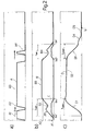
- Figure 2 is a diagram relating to a sequence of positions of some components of the electrohydraulic unit of Figure 1 in accordance with a first operating mode;
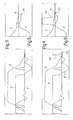
- Figures 3 and 4 are diagrams relating to a sequence of positions of some components of the electrohydraulic unit of Figure 1 and of velocities assumed by the valve;
- Figures 5 and 6 are magnified portions respectively of the diagrams of Figures 3 and 4;
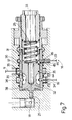
- Figure 7 is a sectional view of a component of the electrohydraulic unit of Figure 1; and
- Figure 8 is a diagram relating to a sequence of positions of some components of the electrohydraulic unit of Figure 1 in accordance with a second operating mode.
- With reference to Figure 1, 1 denotes the overall electrohydraulic unit for actuating the
valves 2 of an endothermic engine M. Figure 1 shows just onevalve 2 coupled with arespective seat 2A, although the electrohydraulic unit 1 is capable of controlling all the intake and exhaust valves of the engine M. In the present description, "opening of thevalve 2" is taken to mean the phase of changing from the closed position of thevalve 2 to the maximally open position; "closure of thevalve 2" is taken mean the phase of changing between the maximally open position of thevalve 2 and the closed position; and "holding" is taken to mean the phase during which thevalve 2 remains in the maximally open position. Consequently, in relation to thevalve 2, the terms open, close and hold have an analogous meaning. The unit 1 comprises ahydraulic circuit 3 and acontrol device 4. In turn, thehydraulic circuit 3 comprises acircuit 5, common to all thevalves 2, and a plurality of actuating devices 6, each of which is associated with arespective valve 2. For the sake of simplicity, Figure 1 shows just one device 6 associated with therespective valve 2. - The
circuit 5 comprises an oil holding tank 7, apumping unit 8 and twobranches respective pressure regulators respective pressure accumulators branches ci rcuit 5, downstream from therespective accumulators control selector 15, aslide valve distributor 16 and ahydraulic actuator 17 rigidly coupled to thevalve 2. Theselector 15 is connected to thebranch 10, to the tank 7 and to abranch 18 that connects theselector 15 to thedistributor 16 in order to control thedistributor 16 itself. - The
distributor 16 is connected to thebranch 9, to the tank 7, to adelivery branch 19 to theactuator 17 and adischarge branch 20 from theactuator 17. Thebranch 19 and thebranch 20 are connected by a discharge branch 21, along which anorifice 22 is provided. The discharge branch 21 andorifice 22 have the function of slowing thevalve 2 in the closing phase and maintaining a constant velocity for closing thevalve 2. In particular, slowing of thevalve 2 takes effect during the final part of the closing stroke of thevalve 2, as will be described below in greater detail in the present description. - The
selector 15 is a three-way valve controlled by anelectromagnet 23 and by aspring 24 and is capable of assuming two positions: when theelectromagnet 23 is not excited, thespring 24 holds the selector in the first position, in which thebranch 10 is closed, while thebranch 18 is connected to the tank 7 (Figure 1); when excited, theelectromagnet 23 overcomes the force of thespring 24 and places theselector 15 in the second position, in which thebranch 10 is connected to thebranch 18. - The
distributor 16 is a four-way valve controlled by apiston 25 and by aspring 26 and is capable of assuming substantially four operating positions shown diagrammatically as P1, P2, P3 and P4 in Figure 1. While theselector 16 has four operating positions P1, P2, P3 and P4, it actually has only two stable positions, namely the end positions indicated as P1 and P4 in Figure 1. The operating positions P2 and P3 are transitional positions between the opposing the operating positions P1 and P4. In the operating position P1, thebranch 20 is connected to the tank 7, while thebranch 9 and thebranch 19 are disconnected; in the operating position P2, all the connections are broken; in the operating position P3, thebranch 9 is connected to thebranch 19, while thedischarge branch 20 is shut off: for this reason, the operating position P3 is defined as the actuating position; the operating position P4 again exhibits the same features as the operating position P2. - The linear
hydraulic actuator 17 comprises acylinder 27, apiston 28 connected to thevalve 2 and aspring 29 capable of holding thevalve 2 in the closed position. Thecylinder 27 has a head 27a and ajacket 27b, along which a side discharge opening 30 is arranged. Thepiston 28 comprises a crown 28a and aside face 28b, which, in specific positions of thepiston 28, closes the opening 30. - In order to understand the functioning of the unit 1 better, it is necessary to describe the
distributor 16 from the structural standpoint and with reference to Figure 7, in which some components of the unit 1 are illustrated from the structural standpoint and bear the same reference numeral as in Figure 1. Thedistributor 16 comprises asleeve 31 and aslide valve 32 that slides inside thesleeve 31 along an axis 33. Thebranch 19, thebranch 9 and thebranch 20 communicate with respective series ofradial holes sleeve 31. Theradial holes radial holes slide valve 32, which comprises twofaces sleeve 31 and are separated by arecess 39. Essentially, there is a geometric relationship between the axial extent of thefaces recess 39 and the axial position of theaxial holes slide valve 32. In particular, the dimensions of theslide valve 32 and thesleeve 31 make it possible to align therecess 39 simultaneously with both series ofholes face 38 with the series ofholes 36, so as to shut off thereturn branch 20 and to supply pressurised oil from thebranch 9 to thebranch 19. The position described corresponds to the operating position P3 of Figure 1 and is not actually a stable position of the slide valve 32: the open cross-section or port available to the oil for passage from thebranch 9 to thebranch 19 varies as a function of the position of theslide valve 32. - The
control device 4 comprises anelectronic control unit 40, which, on the basis of data captured from the engine M, such as for example rotational speed RPM and other operating parameters, determines the opening time and closing time for eachvalve 2. Theunit 40 thus controls theelectromagnet 23 in order to actuate in cascade theselector 15 of thedistributor 16 and thelinear actuator 17. Thecontrol device 4 furthermore comprises asensor 41 for the temperature T of the oil; asensor 42 for the position of thedistributor 16 and asensor 43 for the impact velocity of thevalve 2. - With reference to Figure 7, the
position sensor 42 comprises twopermanent magnets sliding component 32 and are arranged at a distance from one another along the axis 33 that is equal to the difference between the strokes of theslide valve 32 required respectively to open and close theholes sensor 42 comprises adetector 46 arranged along thesleeve 31 in order to detect the opening of thehole 35 and the closure of thehole 34 in the stroke moving from left to right in Figure 7 and vice versa in the stroke moving from right to left. The geometry of thedistributor 16 ensures that the connection between thebranch 9 and thebranch 19 begins after theslide valve 32 has been displaced by a first amount and is brought to an end after theslide valve 32 has been displaced by a second amount. In this manner, thedetector 46 detects the passage of the magnet 45 (first amount of displacement), which corresponds to the opening of the open cross-section, and the passage of themagnet 44, which corresponds to the closure of the open cross-section during displacement from P1 to P4. The order of detection is reversed on a return displacement from P4 to P1. Essentially, with twothresholds single detector 46, it is possible to identify the opening and closing positions of the open cross-section due to the displacement of theslide valve 32 in both directions. - The
sensor 43 takes the form of an accelerometer which detects the impact that occurs when thevalve 2 comes back into contact with therespective seat 2A. Thesensor 43 can also be a detonation sensor, the signal from which, when detected and filtered, is correlated with the impact velocity VI for eachvalve 2. Thus, by means of a single accelerometer fitted on the engine M, it is possible to detect the impact velocity for eachvalve 2 of the engine M. - The
unit 40, besides controlling theelectromagnet 23, also controls thepressure regulators variable cross-section orifice 22. - In service, movement of the
valve 2 proceeds in accordance with the diagram shown in Figure 2, part a) of which shows the curve A, which indicates the displacement (y-coordinates) of theselector 15 as a function of time (x-coordinates); part b) shows the curve B, which indicates the position (y-coordinates) of thedistributor 16 and the curve C which indicates the open cross-section or port (y-coordinates) connecting thebranch 9 and thebranch 19 as a function of time (x-coordinates); and part c) shows the curve D, which indicates the position (y-coordinates) of thevalve 2 as a function of time (x-coordinates). Parts a), b) and c) are aligned in such a manner that their respective time scales are in phase throughout parts a), b) and c). In this manner, it is possible to compare the relationships between the positions of theselector 15, thedistributor 16, the effect of the position of thedistributor 16 on the open cross-section, and the position of thevalve 2. - The principle of operation is based on the fact that the
unit 40 excites theelectromagnet 23 according to a cycle assigned as a function of engine status: namely operating parameters such as torque, rotational speed or emissions. With reference to Figure 2 c), thevalve 2 has a predetermined time topen that is necessary to open thevalve 2 and a predetermined time tclose that is necessary to close thevalve 2, at least in part, which times are substantially constant and are determined by the equivalent mass and rigidity of the system, the system being taken to comprise the assembly formed by thepiston 28, thevalve 2, thespring 29 and the oil contained in thecylinder 27. The times topen and tclose are influenced by the characteristics of the oil and are obtained experimentally. In order to obtain the required trajectory of thevalve 2 while simultaneously minimising energy losses, the opening time of the open cross-section must correspond to topen during the opening phase of thevalve 2 and to the time tclose during the closing phase of thevalve 2. Essentially, the times topen and tclose are substantially equal to half the first oscillation period of a system defined by thevalve 2, thepiston 28, thespring 29 and the oil. - However, as previously mentioned, the operating position P3 of the
distributor 16 is not a stable position and, therefore, without detecting the position of theslide valve 32, it is not possible to detect the opening time of the open cross-section. In practice, as shown in Figure 2 b), thesensor 42 detects two points X1 and X2 of the curve B in order to determine the curve C of the open cross-section. In practice, theunit 40 detects the times tX1 and tX2 and calculates the time tspo, which is equal to the difference between tX2' and tX1' and represents the time that elapses between the detection of the two points X1 and X2: the time tspo accordingly corresponds to the opening time of the open cross-section during the opening phase of thevalve 2 and can be defined as the actuation time of theactuator 17 during the opening phase of thevalve 2. Similarly, theunit 40 calculates the time tspc which elapses between the detection of the two points X2 and X1: the time tspc is equal to the difference between the times tX1 and tX2, and corresponds to the opening time of the open cross-section during the closing phase of thevalve 2, which can be defined as the actuation time of theactuator 17 during the closing phase of thevalve 2. Theunit 40 subsequently calculates the respective differences between the values for tspo and tspc and the values for topen and tclose and outputs respective error signals Eo and Ec when the calculated differences exceed defined threshold values H and K. - With reference to Figure 1, in the absence of error signals Eo, Ec, the
selector 15 operates according to a cycle in which change from the position shown in Figure 1 to the position in which thebranches valve 2, holding of the connection between thebranches valve 2 being held in the open position and breaking of the connection between thebranches valve 2. - With reference to Figure 2, the
unit 40 displaces the selector 15 (portion A1 of the curve A), in order to open the valve (portion B1 of the curve B of thedistributor 16 and portions D1 of the curve D of the valve 2). Subsequently, in the presence of an error signal Eo, theunit 40 displaces the selector 15 (portion A2 of the curve A) in order to break the connection between thebranches valve 2 after the point X1 has been detected and before the point X2 has been detected in order to delay the closure of the open port and to synchronise the time tspo with the time topen. Thedistributor 16 oscillates (portion B2 of the curve B) in the connection position between thebranches - While the valve 2 (portion D2 of the curve D, Figure 2 c)) is being held in the open position, the
selector 15 remains in the connection position between thebranches 10 and 18 (portion A3 of the curve A of the curve 2a)), such that thedistributor 16 is arranged in the operating position P4 (portion B3 of the curve B, Figure 2 b)). - The breaking of the connection between the
branches - In the presence of error signal Ec, the
unit 40 temporarily connects thebranch 10 to the branch 18 (portion A4 of the curve A, Figure 2 a) during the closing phase of thevalve 2 after the point X2 has been detected and before the point X1 has been detected in order to delay the closure of the open port. Thedistributor 16 oscillates during the closing phase in a position of connection between thebranches - In the example described above and shown diagrammatically in Figure 2, the
selector 15 is actuated after tX1 has been detected in order to cut off thebranches - In each cycle, the
unit 40 calculates the error signals Eo and Ec and optionally controls the times Tspo and Tspc in the above-described manner in the subsequent cycle, adjusting the displacement of thedistributor 16 as a function of the times topen and tclose. - When reference is made in the above description to a closed-loop operating mode, it should be understood that the system is also capable of operating in open-loop mode according to a predetermined cycle that provides for the position of the
selector 15 to be varied in order to control the connection times tspo and tspc. - In order to understand the dynamic behaviour of the unit 1, it is necessary to explain that during the opening of the
valve 2, the assembly formed by theactuator 17, in the present case thepiston 28 and thevalve 2, performs, over the predetermined time topen, a larger stroke than that necessary to define a balance between the force of thespring 29 and the oil pressure in thebranch 9 of thecircuit 3. This is attributable to the dynamic behaviour of thesystem comprising piston 28,valve 2,spring 29 and oil, which is subject to a first oscillation with a specific period, characteristic of the particular system. Since, during the opening phase of thevalve 2, the connection between thebranch 9 and thebranch 19 is closed and thebranch 20 is shut off at the maximum oscillation amplitude, the time required to establish a balance between the force of thespring 29 and the force of the pressure in thebranch 9 is not available. In fact, thespring 29, having been dynamically compressed under the inertial thrust of the system, brings about a pressure in theclosed cylinder 27 that is greater than that in thebranch 9. Consequently, during the closing phase of thevalve 2, when thebranches cylinder 27 flows back through thebranch 19 to thebranch 9. Essentially, thebranch 19 performs not only the function of a delivery branch, but also that of a return branch. The phase of expelling the oil from theactuator 17 through thebranch 9 is completed within the time tclose, which is substantially equal to half the oscillation period of the system. Obviously, friction means that recovery is incomplete and that thevalve 2 is not completely closed at the end of said phase, but occupies an intermediate position between the maximally open position and the closed position. - Subsequently, the
distributor 16 reaches the operating position P1, in which the oil contained in thecylinder 27 is initially discharged through theopening 30 and the branch 20 (portion D4 of the curve D, Figure 2 c)). Displacement of thepiston 28 during discharge of the oil to the tank 7 brings about progressive closure of theopening 30 and thus the residual oil contained in thecylinder 27 is discharged through the discharge branch 21 and the orifice 22 (portion D5 of the curve D, Figure 2 b)). Theorifice 22 has the function of slowing the closure of thevalve 2 and maintaining a substantially constant closing velocity. Theunit 40 is capable of varying the open cross-section of theorifice 22 so as to control the closing velocity. - With reference to Figure 3, as well as the curve D relating to the displacement of the
valve 2 and the curve A relating to the displacement of theselector 15, the curve F is shown relating to the velocity of thevalve 2. With reference to Figure 5, the final portion F1 of the curve F comprises a substantially horizontal portion indicating the constant velocity (approx. 0.35 m/s) and a substantially vertical portion that indicates the impact (abrupt deceleration). With reference to Figure 4, theselector 15 is activated for a moment during the approach phase of thevalve 2 in such a manner as to modify the final portion F2 of the curve F. This has the effect of reducing the velocity to approx. 0.05 m/s in order to reduce the impact. - From a functional standpoint, the
sensor 43 detects the impact velocity VI and the moment tc at which thevalve 2 is closed in itsrespective seat 2A. Theunit 40 captures the value of the impact velocity VI and calculates the nominal impact velocity VN, which is a function of the rotational speed RPM of the engine M: at low rotational speeds RPM, low impact velocities VI are preferable, while at high rotational speeds, higher impact velocities VI can be tolerated. Thecontrol unit 40 calculates the difference between the impact velocity VI and the nominal velocity VN. When said difference is greater than a predetermined threshold value S, theunit 40 calculates and outputs an error signal EV and actuates theelectromagnet 23 for a short moment during the final closure phase of thevalve 2 in order to displace thedistributor 16 from the operating position P1 and to cut off discharge from thecylinder 27. In some cases, it could be necessary not only to cut off discharge, but even to deliver pressurised oil into theactuator 17 during the discharge phase in order to achieve more consistent deceleration. The pulse is delivered immediately before the moment tc detected in the preceding cycle. - Essentially, control of the
electromagnet 23 permits two main adjustments: synchronisation of the motion of theslide valve 32 with the motion of the valve 2: namely synchronisation of the connection times tspo and tspc between thebranches valve 2 in order to effect efficient opening and closure of thevalve 2 and energy recovery and deceleration of the closing velocity of thevalve 2 in order to minimise the impact velocity VI of thevalve 2. In addition to these adjustments, there is also the fact that, under certain operating conditions, for example at low temperature, it is preferable to operate dissipatively rather than with energy recovery. Energy recovery is achieved by requiring that the connection times tspo and tspc substantially correspond to the predetermined times topen and tclose. In contrast, dissipative operation is implemented by requiring that the connection times tspo and tspc differ substantially from the predetermined times topen and tclose. - To this end, the
sensor 41 detects the oil temperature T and theunit 40 calculates the threshold values K and H as a function of the temperature T: the values of K and H will be closer to zero, the higher is the oil temperature T. In this manner, operation with energy recovery and operation with energy dissipation as a function of oil temperature T are implemented using the same control cycle. - With reference to Figure 8, an operating mode is shown in which the
distributor 16 occupies only the operating positions P1 and P2 during a cycle of thevalve 2. Essentially, by controlling theselector 15, it is possible to achieve limited displacement of thedistributor 16 so as to keep thedistributor 16 in the position P2. In practice, thecontrol unit 40 captures the moment tX1 and subsequently controls theselector 15 so as to avoid exceeding the point X2 and, subsequently, detects the moment tX1' which corresponds to the closing time of the connection between thebranch 9 and thehydraulic actuator 17. Theunit 40 calculates the connection time tspoc as the difference between the times tx1' and tx1 and compares the time tspoc with a predetermined time toc characteristic of the system as defined above: in this case, toc takes account of the opening and partial closure phase of thevalve 2 and is substantially equal to the previously defined oscillation period of the system. When the difference between the connection time tspoc and the predetermined time toc exceeds a threshold value J, theunit 40 outputs an error signal Eoc, which is used in the subsequent cycle to control theselector 15 and to correct the time tspoc. - The threshold value J is also a function of the oil temperature T, as described above in relation to the threshold values H and K so as to achieve operation with energy recovery and dissipative operation. Moreover, in this case too, it is possible to operate in both closed-loop and open-loop mode.
- Further functions of the
control unit 40 include regulating the pressure in thebranch 9 by means of thepressure regulator 11 and so varying the maximum opening of thevalve 2, and regulating the pressure in thebranch 10 by means of thepressure regulator 12 and varying the control pressure of thedistributor 16 and obtaining different dynamic behaviour of thedistributor 16. - The present description has made specific reference to oil as the liquid used in the hydraulic system, but it is understood that oil can be replaced with any other liquid without consequently extending beyond the scope of protection of the present invention.
Claims (32)
- Method for controlling an electrohydraulic unit (1) for actuating the valves (2) of an endothermic engine (M), in which the electrohydraulic unit (1) comprises a hydraulic actuator (17) for opening a respective valve (2) with a pressurised liquid, and a spring (29) that is antagonistic to the hydraulic actuator (17) in order to close the valve (2); the method being characterised in that the connection time (tspo; tspc; tspoc) between the hydraulic actuator (17) and a first branch (9) containing said pressurised liquid is controlled as a function of a predetermined time (topen tclose; toc) characteristic of the electrohydraulic unit.
- Method according to Claim 1, characterised in that said predetermined time (topen; tclose; toc) characteristic of the electrohydraulic unit (1) is correlated with the dynamic behaviour of a system comprising said hydraulic actuator (17), the valve (2), the spring (29) and the liquid.
- Method according to Claim 1 or 2, characterised in that said phase of controlling said connection time (tspo; tspc; tspoc) provides for the requirement that said connection time (tspo; tspc; tspoc) is substantially equal to the predetermined time (topen; tclose; toc).
- Method according to Claim 1 or 2, characterised in that said phase of controlling said connection time (tspo; tspc; tspoc) provides for the requirement that said connection time (tspo; tspc; tspoc) differs substantially from the predetermined time (topen; tclose; toc).
- Method according to any one of Claims 1 to 4, characterised in that the electrohydraulic unit (1) comprises a distributor (16) for controlling the hydraulic actuator (17), said first branch (9), which connects the distributor (16) to a pumping unit (8) for a pressurised liquid, a second branch (19), which connects the distributor (16) to the hydraulic actuator (17); said distributor (16) being capable of connecting the first and second branches (9, 19); said connection time (tspo; tspc; tspoc) corresponding to the connection time between the first branch (9) and the second branch (19).
- Method according to Claim 5, characterised in that said distributor (16) is controlled by a hydraulic selector (15) that can move between two positions; the method providing that the distributor (16) is controlled by means of the hydraulic selector (15) in order to control the connection time (tspo; tspo; tspoc).
- Method according to any one of Claims 1 to 4, characterised in that said connection time (tspo; tspc; tspoc) is defined.
- Method according to Claim 7, characterised in that the connection time (tspo; tspc; tspoc) is compared with said predetermined time (topen; tclose; toc); and in that an error signal (Eo; Ec; Eoc) is output when the difference between the predetermined time (topen; tclose; toc) and the connection time (tspo; tspc; tspoc) exceeds a defined threshold (K; H; J).
- Method according to Claim 7, characterised in that said distributor (16) is controlled as a function of said error signal (Eo, Ec, Eoc).
- Method according to any one of Claims 7 to 9, characterised in that said phase of defining said connection time (tspo; tspc; tspoc) provides for the capture of a first moment (tX1; tX2'; tX1), at which the connection between the first and the second branches (9, 19) is made, and a second moment (tX2; tX1'; tX1') at which the connection between the first and the second branches (9, 19) is broken.
- Method according to Claim 10, characterised in that said distributor (16) comprises a slide valve (32) that slides within a sleeve (31) connected to the first and second branches (9, 19); the method providing for the detection of a first position (X1; X2; X1) of the slide valve (32) corresponding to the start of the connection and a second position (X2; X1; X1) corresponding to the end of the connection and the capture of said first moment (tX1; tX2'; tX1) and said second moment (tX2; tX1'; tX1').
- Method according to any one of Claims 8 to 11, characterised in that said threshold (K; H; J) is a function of operating parameters of the electrohydraulic unit (1).
- Method according to Claim 12, characterised in that said threshold (H; K; J) is a function of the temperature (T) of the liquid.
- Method according to any one of the preceding claims, characterised in that said predetermined time (topen) is equal to the opening time of the valve (2) between the closed position and the maximally open position; said predetermined time (topen) being a function of the mass and rigidity of the system comprising hydraulic actuator (17), valve (2) and spring (29) and the liquid and being substantially equal to half the oscillation period of said system.
- Method according to any one of Claims 1 to 13, characterised in that said predetermined time (tclose) is equal to a partial closure time of the valve (2) between the maximally open position and an intermediate position between the maximally open position and the closed position; said predetermined time (tclose) being a function of the mass and rigidity of the system comprising hydraulic actuator (17), valve (2) and spring (29) and the liquid, and being substantially equal to half the oscillation period of said system.
- Method according to any one of Claims 1 to 13, characterised in that said predetermined time (toc) is equal to an opening and partial closure time of the valve (2) over a cycle comprising an initial closed position, a maximally open position and an intermediate position between the closed and maximally open positions; said predetermined time (toc) being a function of the mass and rigidity of the system comprising hydraulic actuator (17), valve (2) and spring (29) and the liquid, and being substantially equal to the oscillation period of the system.
- Method according to any one of Claims 12 to 14, in which said maximally open position of the valve (2) is a function of the pressure of said liquid; the method providing that the pressure of said liquid is varied to modify the maximally open position of the valve (2).
- Device for controlling an electrohydraulic unit (1) for actuating the valves (2) of an endothermic engine (M), in which the electrohydraulic unit (1) comprises a hydraulic actuator (17) for opening a respective valve (2) with a pressurised liquid, and a spring (29) that is antagonistic to the hydraulic actuator (17) in order to close the valve (2); the device being characterised in that it comprises control means (40, 15, 16) for controlling the connection time (tspo; tspc; tspoc) between the hydraulic actuator (17) and a first branch (9) containing said pressurised liquid as a function of a predetermined time (topen; tclose; toc) characteristic of the electrohydraulic unit (1).
- Device according to Claim 18, characterised in that said predetermined time (topen; tclose; toc) characteristic of the electrohydraulic unit is correlated with the dynamic behaviour of a system comprising said hydraulic actuator (17), the valve (2), the spring (29) and the liquid.
- Device according to Claim 18 or 19, characterised in that the electrohydraulic unit (1) comprises a distributor (16) for controlling the hydraulic actuator (17), said first branch (9), which connects the distributor (16) to a pumping unit (8) for a pressurised liquid, a second branch (19), which connects the distributor (16) to the hydraulic actuator (17); said distributor (16) being capable of connecting the first and the second branches (9, 19); said connection time (tspo; tspc; tspoc) corresponding to the connection time between the first branch (9) and the second branch (19).
- Device according to one of Claims 18 to 20, characterised in that it comprises a hydraulic selector (15) for controlling said distributor (16) as a function of the connection time (tspo; tspc; tspoc).
- Device according to Claim 16 or 17, characterised in that it comprises means (40, 42) for capturing said connection time (tspo; tspc; tspoc).
- Device according to Claim 22, characterised in that it comprises means for comparing (40) the connection time (tspo; tspc; tspoc) with said predetermined time (topen; tclose; toc); and means for outputting (40) an error signal (Eo; Ec; Eoc) when the difference between the predetermined time (topen, tclose; toc) and the connection time (tspo; tspc; tspoc) exceeds a defined threshold (K; H; J).
- Device according to Claim 22 or 23, characterised in that it comprises means for capturing (40, 42) a first moment (tX1; tX2'; tX1) at which the connection between the first and second branches (9, 19) is made and a second moment (tX2; tX1'; tX1') at which the connection between the first and second branches (9, 19) is broken.
- Device according to Claim 24, characterised in that said distributor (16) comprises a slide valve (32) that slides within a sleeve (31) connected to the first and second branches (9, 19); the device comprising means for capturing (40, 42) a first position (X1; X2; X1) of the slide valve (32) corresponding to the start of the connection and a second position (X2; X1; X1) corresponding to the end of the connection and said first moment (tX1; tX2'; tX1) and said second moment (tX2; tX1'; tX1').
- Device according to Claim 25, characterised in that the capture means (40, 42) comprise a threshold sensor (42).
- Device according to Claim 26, characterised in that said threshold sensor (42) comprises two thresholds (44, 45) fitted on the slide valve (32) and a fixed detector (46).
- Device according to Claim 27, characterised in that said thresholds (44, 45) are permanent magnets.
- Device according to any one of Claims 18 to 28, characterised in that said predetermined time (topen) is equal to the opening time of the valve (2) between the closed position and the maximally open position; said predetermined time (topen) being a function of the mass and rigidity of the system comprising hydraulic actuator (17), valve (2) and spring (29) and the liquid, and being substantially equal to half the oscillation period of said system.
- Device according to any one of Claims 18 to 28, characterised in that said predetermined time (tclose) is equal to a partial closure time of the valve (2) between the maximally open position and an intermediate position between the maximally open and closed positions; said predetermined time (tclose) being a function of the mass and rigidity of the system comprising hydraulic actuator (17), valve (2) and spring (29) and the liquid and being substantially equal to half the oscillation period of said system.
- Device according to any one of Claims 18 to 28, characterised in that said predetermined time (toc) is equal to an opening and partial closure time of the valve (2) over a cycle comprising an initial closed position, a maximally open position and an intermediate position between the closed and maximally open positions; said predetermined time (toc) being a function of the mass and rigidity of the system comprising hydraulic actuator (17), valve (2) and spring (29) and the liquid, and being substantially equal to the oscillation period of the system.
- Device according to any one of Claims 29 to 31, in which said maximally open position of the valve (2) is a function of the pressure of said liquid; the device being characterised in that it comprises a pressure regulator (11) for varying the pressure of said liquid and modifying the maximally open position of the valve (2).
Priority Applications (1)
| Application Number | Priority Date | Filing Date | Title |
|---|---|---|---|
| PL04102847T PL1491730T3 (en) | 2003-06-23 | 2004-06-21 | Method and device for controlling an electrohydraulic valve actuating unit of a combustion engine |
Applications Claiming Priority (2)
| Application Number | Priority Date | Filing Date | Title |
|---|---|---|---|
| ITBO20030388 | 2003-06-23 | ||
| IT000388A ITBO20030388A1 (en) | 2003-06-23 | 2003-06-23 | METHOD AND CONTROL DEVICE OF AN ELECTROHYDRAULIC GROUP |
Publications (2)
| Publication Number | Publication Date |
|---|---|
| EP1491730A1 true EP1491730A1 (en) | 2004-12-29 |
| EP1491730B1 EP1491730B1 (en) | 2008-12-03 |
Family
ID=33398039
Family Applications (1)
| Application Number | Title | Priority Date | Filing Date |
|---|---|---|---|
| EP04102847A Expired - Lifetime EP1491730B1 (en) | 2003-06-23 | 2004-06-21 | Method and device for controlling an electrohydraulic valve actuating unit of a combustion engine |
Country Status (10)
| Country | Link |
|---|---|
| US (1) | US7044092B2 (en) |
| EP (1) | EP1491730B1 (en) |
| CN (1) | CN100540855C (en) |
| AT (1) | ATE416302T1 (en) |
| BR (1) | BRPI0404869B1 (en) |
| DE (1) | DE602004018064D1 (en) |
| ES (1) | ES2316924T3 (en) |
| IT (1) | ITBO20030388A1 (en) |
| PL (1) | PL1491730T3 (en) |
| PT (1) | PT1491730E (en) |
Families Citing this family (5)
| Publication number | Priority date | Publication date | Assignee | Title |
|---|---|---|---|---|
| US7261070B2 (en) * | 2005-03-01 | 2007-08-28 | Jones James W | Linear fluid engine |
| DE102007025619B4 (en) * | 2007-06-01 | 2012-11-15 | Robert Bosch Gmbh | Method and device for controlling a hydraulic actuator |
| US9863293B2 (en) * | 2012-08-01 | 2018-01-09 | GM Global Technology Operations LLC | Variable valve actuation system including an accumulator and a method for controlling the variable valve actuation system |
| DE102013207863A1 (en) * | 2013-04-30 | 2014-10-30 | Mahle International Gmbh | Device for controlling a gas exchange valve of an internal combustion engine |
| DE102014002309B4 (en) * | 2014-02-19 | 2016-01-07 | Hydac Electronic Gmbh | control device |
Citations (6)
| Publication number | Priority date | Publication date | Assignee | Title |
|---|---|---|---|---|
| DE3741214A1 (en) * | 1987-12-05 | 1989-06-15 | Martin Roth | Hydraulic variable valve timing system for reciprocating-piston engines or machines |
| EP0647770A2 (en) * | 1991-06-24 | 1995-04-12 | Ford Motor Company Limited | Hydraulically operated valve control system for an internal combustion engine |
| EP1233152A1 (en) | 2001-02-20 | 2002-08-21 | MAGNETI MARELLI POWERTRAIN S.p.A. | Electrohydraulic device for operating the valves of a combustion engine |
| US20020157650A1 (en) * | 2000-02-16 | 2002-10-31 | Herman Gaessler | Method and circuit system for operating a solenoid valve |
| WO2003008794A2 (en) | 2000-12-20 | 2003-01-30 | Siemens Vdo Automotive Corporation | Air fuel module |
| US6581557B1 (en) * | 1999-12-30 | 2003-06-24 | Robert Bosch Gmbh | Valve control for an internal combustion engine |
Family Cites Families (3)
| Publication number | Priority date | Publication date | Assignee | Title |
|---|---|---|---|---|
| US6739293B2 (en) * | 2000-12-04 | 2004-05-25 | Sturman Industries, Inc. | Hydraulic valve actuation systems and methods |
| US6827050B2 (en) * | 2001-12-21 | 2004-12-07 | Caterpillar Inc | Fluid control valve actuating system |
| US6886510B2 (en) * | 2003-04-02 | 2005-05-03 | General Motors Corporation | Engine valve actuator assembly with dual hydraulic feedback |
-
2003
- 2003-06-23 IT IT000388A patent/ITBO20030388A1/en unknown
-
2004
- 2004-06-21 EP EP04102847A patent/EP1491730B1/en not_active Expired - Lifetime
- 2004-06-21 PL PL04102847T patent/PL1491730T3/en unknown
- 2004-06-21 DE DE602004018064T patent/DE602004018064D1/en not_active Expired - Lifetime
- 2004-06-21 AT AT04102847T patent/ATE416302T1/en not_active IP Right Cessation
- 2004-06-21 PT PT04102847T patent/PT1491730E/en unknown
- 2004-06-21 ES ES04102847T patent/ES2316924T3/en not_active Expired - Lifetime
- 2004-06-22 US US10/873,728 patent/US7044092B2/en not_active Expired - Lifetime
- 2004-06-23 BR BRPI0404869-5A patent/BRPI0404869B1/en not_active IP Right Cessation
- 2004-06-23 CN CNB200410061619XA patent/CN100540855C/en not_active Expired - Fee Related
Patent Citations (6)
| Publication number | Priority date | Publication date | Assignee | Title |
|---|---|---|---|---|
| DE3741214A1 (en) * | 1987-12-05 | 1989-06-15 | Martin Roth | Hydraulic variable valve timing system for reciprocating-piston engines or machines |
| EP0647770A2 (en) * | 1991-06-24 | 1995-04-12 | Ford Motor Company Limited | Hydraulically operated valve control system for an internal combustion engine |
| US6581557B1 (en) * | 1999-12-30 | 2003-06-24 | Robert Bosch Gmbh | Valve control for an internal combustion engine |
| US20020157650A1 (en) * | 2000-02-16 | 2002-10-31 | Herman Gaessler | Method and circuit system for operating a solenoid valve |
| WO2003008794A2 (en) | 2000-12-20 | 2003-01-30 | Siemens Vdo Automotive Corporation | Air fuel module |
| EP1233152A1 (en) | 2001-02-20 | 2002-08-21 | MAGNETI MARELLI POWERTRAIN S.p.A. | Electrohydraulic device for operating the valves of a combustion engine |
Also Published As
| Publication number | Publication date |
|---|---|
| ITBO20030388A1 (en) | 2004-12-24 |
| BRPI0404869B1 (en) | 2012-10-02 |
| BRPI0404869A (en) | 2005-02-22 |
| ATE416302T1 (en) | 2008-12-15 |
| CN100540855C (en) | 2009-09-16 |
| EP1491730B1 (en) | 2008-12-03 |
| PL1491730T3 (en) | 2009-04-30 |
| CN1573031A (en) | 2005-02-02 |
| ES2316924T3 (en) | 2009-04-16 |
| DE602004018064D1 (en) | 2009-01-15 |
| US7044092B2 (en) | 2006-05-16 |
| PT1491730E (en) | 2009-02-02 |
| US20050022759A1 (en) | 2005-02-03 |
Similar Documents
| Publication | Publication Date | Title |
|---|---|---|
| US6584885B2 (en) | Variable lift actuator | |
| EP1491732B1 (en) | Method and device for controlling the speed of the valves of an internal combustion engine | |
| EP0925439A2 (en) | A hydraulically controlled camless valve system for an internal combustion engine | |
| US6510037B1 (en) | Method for monitoring an electromagnetic actuator | |
| EP1491730B1 (en) | Method and device for controlling an electrohydraulic valve actuating unit of a combustion engine | |
| EP1617061B1 (en) | Idling speed controller of internal combustion engine, internal combustion engine controller and internal combustion engine | |
| EP3283738B1 (en) | Actuator for axial displacement of an object | |
| EP1491731B1 (en) | Electrohydraulic valve actuating unit of an internal combustion engine | |
| EP1918573B1 (en) | Fuel injection apparatus for engines | |
| US20220042428A1 (en) | Hydraulic Drive for Accelerating and Braking Dynamically Moving Components | |
| EP3283737B1 (en) | Pneumatic actuator for an engine valve | |
| EP1607593B1 (en) | Exhaust valve drive control method and device | |
| CN100432378C (en) | Method for generating pressure pulses, pressure pulse generator and piston engine provided with said generator | |
| US20150369093A1 (en) | Variable electrohydraulic valve control system | |
| EP2206940A1 (en) | Valve actuator | |
| SE526975C2 (en) | Method for generating pressure pulses, pressure pulse generator and one with such a piston motor | |
| EP1957761B1 (en) | Cold temperature operation for added motion valve system | |
| US20040101420A1 (en) | Solenoid regulated pump assembly | |
| US6631699B2 (en) | Air fuel module | |
| WO2015155407A1 (en) | Flow control valve and method for operating a flow control valve | |
| JP3796793B2 (en) | Timer device for fuel injection pump | |
| Herranen et al. | Optimization and energy consumption of Electro-Hydraulic Valve Actuation system through valve event timing range |
Legal Events
| Date | Code | Title | Description |
|---|---|---|---|
| PUAI | Public reference made under article 153(3) epc to a published international application that has entered the european phase |
Free format text: ORIGINAL CODE: 0009012 |
|
| AK | Designated contracting states |
Kind code of ref document: A1 Designated state(s): AT BE BG CH CY CZ DE DK EE ES FI FR GB GR HU IE IT LI LU MC NL PL PT RO SE SI SK TR |
|
| AX | Request for extension of the european patent |
Extension state: AL HR LT LV MK |
|
| 17P | Request for examination filed |
Effective date: 20050624 |
|
| AKX | Designation fees paid |
Designated state(s): AT BE BG CH CY CZ DE DK EE ES FI FR GB GR HU IE IT LI LU MC NL PL PT RO SE SI SK TR |
|
| GRAP | Despatch of communication of intention to grant a patent |
Free format text: ORIGINAL CODE: EPIDOSNIGR1 |
|
| GRAS | Grant fee paid |
Free format text: ORIGINAL CODE: EPIDOSNIGR3 |
|
| GRAA | (expected) grant |
Free format text: ORIGINAL CODE: 0009210 |
|
| AK | Designated contracting states |
Kind code of ref document: B1 Designated state(s): AT BE BG CH CY CZ DE DK EE ES FI FR GB GR HU IE IT LI LU MC NL PL PT RO SE SI SK TR |
|
| REG | Reference to a national code |
Ref country code: GB Ref legal event code: FG4D |
|
| REG | Reference to a national code |
Ref country code: CH Ref legal event code: EP |
|
| REG | Reference to a national code |
Ref country code: IE Ref legal event code: FG4D |
|
| REF | Corresponds to: |
Ref document number: 602004018064 Country of ref document: DE Date of ref document: 20090115 Kind code of ref document: P |
|
| REG | Reference to a national code |
Ref country code: PT Ref legal event code: SC4A Free format text: AVAILABILITY OF NATIONAL TRANSLATION Effective date: 20090120 |
|
| REG | Reference to a national code |
Ref country code: SE Ref legal event code: TRGR |
|
| REG | Reference to a national code |
Ref country code: ES Ref legal event code: FG2A Ref document number: 2316924 Country of ref document: ES Kind code of ref document: T3 |
|
| REG | Reference to a national code |
Ref country code: PL Ref legal event code: T3 |
|
| NLV1 | Nl: lapsed or annulled due to failure to fulfill the requirements of art. 29p and 29m of the patents act | ||
| PG25 | Lapsed in a contracting state [announced via postgrant information from national office to epo] |
Ref country code: SI Free format text: LAPSE BECAUSE OF FAILURE TO SUBMIT A TRANSLATION OF THE DESCRIPTION OR TO PAY THE FEE WITHIN THE PRESCRIBED TIME-LIMIT Effective date: 20081203 Ref country code: NL Free format text: LAPSE BECAUSE OF FAILURE TO SUBMIT A TRANSLATION OF THE DESCRIPTION OR TO PAY THE FEE WITHIN THE PRESCRIBED TIME-LIMIT Effective date: 20081203 Ref country code: FI Free format text: LAPSE BECAUSE OF FAILURE TO SUBMIT A TRANSLATION OF THE DESCRIPTION OR TO PAY THE FEE WITHIN THE PRESCRIBED TIME-LIMIT Effective date: 20081203 |
|
| PG25 | Lapsed in a contracting state [announced via postgrant information from national office to epo] |
Ref country code: RO Free format text: LAPSE BECAUSE OF FAILURE TO SUBMIT A TRANSLATION OF THE DESCRIPTION OR TO PAY THE FEE WITHIN THE PRESCRIBED TIME-LIMIT Effective date: 20081203 Ref country code: BG Free format text: LAPSE BECAUSE OF FAILURE TO SUBMIT A TRANSLATION OF THE DESCRIPTION OR TO PAY THE FEE WITHIN THE PRESCRIBED TIME-LIMIT Effective date: 20090303 Ref country code: EE Free format text: LAPSE BECAUSE OF FAILURE TO SUBMIT A TRANSLATION OF THE DESCRIPTION OR TO PAY THE FEE WITHIN THE PRESCRIBED TIME-LIMIT Effective date: 20081203 Ref country code: BE Free format text: LAPSE BECAUSE OF FAILURE TO SUBMIT A TRANSLATION OF THE DESCRIPTION OR TO PAY THE FEE WITHIN THE PRESCRIBED TIME-LIMIT Effective date: 20081203 |
|
| PG25 | Lapsed in a contracting state [announced via postgrant information from national office to epo] |
Ref country code: AT Free format text: LAPSE BECAUSE OF FAILURE TO SUBMIT A TRANSLATION OF THE DESCRIPTION OR TO PAY THE FEE WITHIN THE PRESCRIBED TIME-LIMIT Effective date: 20081203 Ref country code: CZ Free format text: LAPSE BECAUSE OF FAILURE TO SUBMIT A TRANSLATION OF THE DESCRIPTION OR TO PAY THE FEE WITHIN THE PRESCRIBED TIME-LIMIT Effective date: 20081203 |
|
| PGFP | Annual fee paid to national office [announced via postgrant information from national office to epo] |
Ref country code: PL Payment date: 20090605 Year of fee payment: 6 Ref country code: PT Payment date: 20090604 Year of fee payment: 6 Ref country code: SE Payment date: 20090623 Year of fee payment: 6 |
|
| PG25 | Lapsed in a contracting state [announced via postgrant information from national office to epo] |
Ref country code: SK Free format text: LAPSE BECAUSE OF FAILURE TO SUBMIT A TRANSLATION OF THE DESCRIPTION OR TO PAY THE FEE WITHIN THE PRESCRIBED TIME-LIMIT Effective date: 20081203 |
|
| PLBE | No opposition filed within time limit |
Free format text: ORIGINAL CODE: 0009261 |
|
| STAA | Information on the status of an ep patent application or granted ep patent |
Free format text: STATUS: NO OPPOSITION FILED WITHIN TIME LIMIT |
|
| PG25 | Lapsed in a contracting state [announced via postgrant information from national office to epo] |
Ref country code: DK Free format text: LAPSE BECAUSE OF FAILURE TO SUBMIT A TRANSLATION OF THE DESCRIPTION OR TO PAY THE FEE WITHIN THE PRESCRIBED TIME-LIMIT Effective date: 20081203 |
|
| PGFP | Annual fee paid to national office [announced via postgrant information from national office to epo] |
Ref country code: ES Payment date: 20090630 Year of fee payment: 6 |
|
| 26N | No opposition filed |
Effective date: 20090904 |
|
| PGFP | Annual fee paid to national office [announced via postgrant information from national office to epo] |
Ref country code: GB Payment date: 20090618 Year of fee payment: 6 |
|
| PG25 | Lapsed in a contracting state [announced via postgrant information from national office to epo] |
Ref country code: MC Free format text: LAPSE BECAUSE OF NON-PAYMENT OF DUE FEES Effective date: 20090630 |
|
| REG | Reference to a national code |
Ref country code: CH Ref legal event code: PL |
|
| REG | Reference to a national code |
Ref country code: IE Ref legal event code: MM4A |
|
| PG25 | Lapsed in a contracting state [announced via postgrant information from national office to epo] |
Ref country code: LI Free format text: LAPSE BECAUSE OF NON-PAYMENT OF DUE FEES Effective date: 20090630 Ref country code: CH Free format text: LAPSE BECAUSE OF NON-PAYMENT OF DUE FEES Effective date: 20090630 Ref country code: IE Free format text: LAPSE BECAUSE OF NON-PAYMENT OF DUE FEES Effective date: 20090621 |
|
| PG25 | Lapsed in a contracting state [announced via postgrant information from national office to epo] |
Ref country code: GR Free format text: LAPSE BECAUSE OF FAILURE TO SUBMIT A TRANSLATION OF THE DESCRIPTION OR TO PAY THE FEE WITHIN THE PRESCRIBED TIME-LIMIT Effective date: 20090304 |
|
| REG | Reference to a national code |
Ref country code: PT Ref legal event code: MM4A Free format text: LAPSE DUE TO NON-PAYMENT OF FEES Effective date: 20101221 |
|
| EUG | Se: european patent has lapsed | ||
| GBPC | Gb: european patent ceased through non-payment of renewal fee |
Effective date: 20100621 |
|
| PG25 | Lapsed in a contracting state [announced via postgrant information from national office to epo] |
Ref country code: PT Free format text: LAPSE BECAUSE OF NON-PAYMENT OF DUE FEES Effective date: 20101221 |
|
| PG25 | Lapsed in a contracting state [announced via postgrant information from national office to epo] |
Ref country code: IT Free format text: LAPSE BECAUSE OF FAILURE TO SUBMIT A TRANSLATION OF THE DESCRIPTION OR TO PAY THE FEE WITHIN THE PRESCRIBED TIME-LIMIT Effective date: 20081203 |
|
| PG25 | Lapsed in a contracting state [announced via postgrant information from national office to epo] |
Ref country code: LU Free format text: LAPSE BECAUSE OF NON-PAYMENT OF DUE FEES Effective date: 20090621 |
|
| PG25 | Lapsed in a contracting state [announced via postgrant information from national office to epo] |
Ref country code: HU Free format text: LAPSE BECAUSE OF FAILURE TO SUBMIT A TRANSLATION OF THE DESCRIPTION OR TO PAY THE FEE WITHIN THE PRESCRIBED TIME-LIMIT Effective date: 20090604 |
|
| REG | Reference to a national code |
Ref country code: ES Ref legal event code: FD2A Effective date: 20110715 |
|
| PG25 | Lapsed in a contracting state [announced via postgrant information from national office to epo] |
Ref country code: ES Free format text: LAPSE BECAUSE OF NON-PAYMENT OF DUE FEES Effective date: 20110705 Ref country code: GB Free format text: LAPSE BECAUSE OF NON-PAYMENT OF DUE FEES Effective date: 20100621 |
|
| PG25 | Lapsed in a contracting state [announced via postgrant information from national office to epo] |
Ref country code: TR Free format text: LAPSE BECAUSE OF FAILURE TO SUBMIT A TRANSLATION OF THE DESCRIPTION OR TO PAY THE FEE WITHIN THE PRESCRIBED TIME-LIMIT Effective date: 20081203 |
|
| PG25 | Lapsed in a contracting state [announced via postgrant information from national office to epo] |
Ref country code: ES Free format text: LAPSE BECAUSE OF NON-PAYMENT OF DUE FEES Effective date: 20100622 Ref country code: CY Free format text: LAPSE BECAUSE OF FAILURE TO SUBMIT A TRANSLATION OF THE DESCRIPTION OR TO PAY THE FEE WITHIN THE PRESCRIBED TIME-LIMIT Effective date: 20081203 |
|
| REG | Reference to a national code |
Ref country code: PL Ref legal event code: LAPE |
|
| PG25 | Lapsed in a contracting state [announced via postgrant information from national office to epo] |
Ref country code: PL Free format text: LAPSE BECAUSE OF NON-PAYMENT OF DUE FEES Effective date: 20100621 |
|
| PG25 | Lapsed in a contracting state [announced via postgrant information from national office to epo] |
Ref country code: SE Free format text: LAPSE BECAUSE OF NON-PAYMENT OF DUE FEES Effective date: 20100622 |
|
| REG | Reference to a national code |
Ref country code: FR Ref legal event code: PLFP Year of fee payment: 12 |
|
| REG | Reference to a national code |
Ref country code: FR Ref legal event code: PLFP Year of fee payment: 13 |
|
| REG | Reference to a national code |
Ref country code: FR Ref legal event code: PLFP Year of fee payment: 14 |
|
| REG | Reference to a national code |
Ref country code: FR Ref legal event code: PLFP Year of fee payment: 15 |
|
| REG | Reference to a national code |
Ref country code: DE Ref legal event code: R079 Ref document number: 602004018064 Country of ref document: DE Free format text: PREVIOUS MAIN CLASS: F01L0009020000 Ipc: F01L0009100000 |
|
| PGFP | Annual fee paid to national office [announced via postgrant information from national office to epo] |
Ref country code: FR Payment date: 20220519 Year of fee payment: 19 Ref country code: DE Payment date: 20220518 Year of fee payment: 19 |
|
| REG | Reference to a national code |
Ref country code: DE Ref legal event code: R119 Ref document number: 602004018064 Country of ref document: DE |
|
| PG25 | Lapsed in a contracting state [announced via postgrant information from national office to epo] |
Ref country code: DE Free format text: LAPSE BECAUSE OF NON-PAYMENT OF DUE FEES Effective date: 20240103 |
|
| PG25 | Lapsed in a contracting state [announced via postgrant information from national office to epo] |
Ref country code: FR Free format text: LAPSE BECAUSE OF NON-PAYMENT OF DUE FEES Effective date: 20230630 |