EP1491345A2 - System and method of printing within circular area - Google Patents
System and method of printing within circular area Download PDFInfo
- Publication number
- EP1491345A2 EP1491345A2 EP04253606A EP04253606A EP1491345A2 EP 1491345 A2 EP1491345 A2 EP 1491345A2 EP 04253606 A EP04253606 A EP 04253606A EP 04253606 A EP04253606 A EP 04253606A EP 1491345 A2 EP1491345 A2 EP 1491345A2
- Authority
- EP
- European Patent Office
- Prior art keywords
- data storage
- optical data
- storage disk
- printhead
- media
- Prior art date
- Legal status (The legal status is an assumption and is not a legal conclusion. Google has not performed a legal analysis and makes no representation as to the accuracy of the status listed.)
- Withdrawn
Links
Images



Classifications
-
- B—PERFORMING OPERATIONS; TRANSPORTING
- B41—PRINTING; LINING MACHINES; TYPEWRITERS; STAMPS
- B41J—TYPEWRITERS; SELECTIVE PRINTING MECHANISMS, i.e. MECHANISMS PRINTING OTHERWISE THAN FROM A FORME; CORRECTION OF TYPOGRAPHICAL ERRORS
- B41J3/00—Typewriters or selective printing or marking mechanisms characterised by the purpose for which they are constructed
- B41J3/407—Typewriters or selective printing or marking mechanisms characterised by the purpose for which they are constructed for marking on special material
- B41J3/4071—Printing on disk-shaped media, e.g. CDs
Definitions
- An inkjet printing system may include a printhead and an ink supply which supplies liquid ink to the printhead.
- the printhead ejects ink drops through a plurality of orifices or nozzles and toward a print media, such as a sheet of paper, so as to print onto the print media.
- the nozzles are arranged in one or more arrays such that properly sequenced ejection of ink from the nozzles causes characters or other images to be printed upon the print media as the printhead and the print media are moved relative to each other.
- Optical data storage disks include a layer which may be read or written on by a laser of an optical drive system.
- Formats of optical data storage disks include, for example, compact disk (CD) media, CD-recordable (CD-R) media, CD-read only memory (CD-ROM) media, CD-rewritable (CD-RW) media, digital versatile disk or digital video disk (DVD) media, DVD-random access memory (DVD-RAM) media, and other types of rewritable optical media, such as magneto-optical (MO) disks and phase-change optical disks.
- CD compact disk
- CD-R compact disk
- CD-ROM CD-read only memory
- CD-RW CD-rewritable
- DVD digital versatile disk or digital video disk
- DVD-RAM DVD-random access memory
- An optical data storage disk may include graphics or images printed on a side of the disk or on a sticker or label adhered to a side of the disk. Since the optical data storage disk is circular in shape, such graphics or images are printed within a circular area. Existing methods of printing typically cannot be performed concurrently with or performed at the same speed as other operations which rely on spinning of the optical data storage disk such as writing or "burning" data to the optical data storage disk.
- One aspect of the present invention provides a method of printing within a circular area of a media.
- the method includes positioning a printhead including at least one column of nozzles above the circular area of the media, including orienting the at least one column of nozzles substantially perpendicular to a radius of the circular area extended below the printhead, rotating the media relative to the printhead, and printing at least one arcuate print pattern within the circular area of the media with the printhead while rotating the media.
- Figure 1 illustrates one embodiment of a portion of an inkjet printing system 10.
- Inkjet printing system 10 includes a printhead assembly 12, an ink supply assembly 14, a mounting assembly 16, a media transport assembly 18, and an electronic controller 20.
- Printhead assembly 12 includes one or more printheads which eject drops of ink, including one or more colored inks, through a plurality of orifices or nozzles 13.
- the drops of ink are directed toward a medium, such as a print media 19, so as to print onto print media 19.
- Print media 19 includes any type of suitable sheet material, such as paper, card stock, envelopes, labels, transparencies, Mylar, and the like or other planar material such as an optical data storage disk, as described below.
- nozzles 13 are arranged in one or more columns or arrays such that properly sequenced ejection of ink from nozzles 13 causes characters, symbols, and/or other graphics or images to be printed upon print media 19 as printhead assembly 12 and print media 19 are moved relative to each other.
- Ink supply assembly 14 supplies ink to printhead assembly 12 and includes a reservoir 15 for storing ink. As such, in one embodiment, ink flows from reservoir 15 to printhead assembly 12. In one embodiment, printhead assembly 12 and ink supply assembly 14 are housed together in an inkjet print cartridge or pen. In another embodiment, ink supply assembly 14 is separate from printhead assembly 12 and supplies ink to printhead assembly 12 through an interface connection, such as a supply tube.
- Mounting assembly 16 positions printhead assembly 12 relative to media transport assembly 18, and media transport assembly 18 positions print media 19 relative to printhead assembly 12.
- a print region 17 within which printhead assembly 12 deposits ink drops is defined adjacent to nozzles 13 in an area between printhead assembly 12 and print media 19.
- print media 19 is rotated during printing by media transport assembly 18.
- Mounting assembly 16 typically includes a carriage and a carriage drive assembly.
- printhead assembly 12 is removably mounted in, and supported by, the carriage, and the carriage drive assembly moves the carriage and, therefore, printhead assembly 12 relative to print media 19.
- a conventional carriage drive assembly may include a carriage guide which supports the carriage, a drive motor, and a belt and pulley system which moves the carriage along the carriage guide.
- Electronic controller 20 communicates with printhead assembly 12, mounting assembly 16, and media transport assembly 18.
- Electronic controller 20 receives data 21 from a host system, such as a computer, and includes memory for temporarily storing data 21.
- data 21 is sent to inkjet printing system 10 along an electronic, infrared, optical or other information transfer path.
- Data 21 represents, for example, an image or graphics to be printed. As such, data 21 forms a print job for inkjet printing system 10 and includes one or more print job commands and/or command parameters.
- electronic controller 20 provides control of printhead assembly 12 including timing control for ejection of ink drops from nozzles 13. As such, electronic controller 20 defines a pattern of ejected ink drops which form characters, symbols, and/or other graphics or images on print media 19. Timing control and, therefore, the pattern of ejected ink drops, is determined by the print job commands and/or command parameters.
- logic and drive circuitry forming a portion of electronic controller 20 is located on printhead assembly 12. In another embodiment, logic and drive circuitry is located off printhead assembly 12.
- print media 19 includes an optical data storage disk 120.
- Optical data storage disk 120 may include, for example, a compact disk (CD) media, a CD-recordable (CD-R) media, a CD-read only memory (CD-ROM) media, a CD-rewritable (CD-RW) media, a digital versatile disk or digital video disk (DVD) media, a DVD-random access memory (DVD-RAM) media, or any other type of writable optical media, such as a magneto-optical (MO) disk or phase-change optical disk.
- CD compact disk
- CD-R compact disk
- CD-ROM CD-read only memory
- CD-RW CD-rewritable
- DVD digital versatile disk or digital video disk
- DVD-RAM DVD-random access memory
- Optical data storage disk 120 includes a circular member 122 having a central bore or opening 124 formed therein.
- opening 124 is sized to accommodate a drive pin or other engagement feature of an optical disk drive (not shown).
- optical data storage disk 120 includes a layer which may be read or written on by a recording head.
- one side of optical data storage disk 120 includes a circular area 126 which provides a printable area for optical data storage disk 120.
- printhead assembly 12 prints graphics or images directly on optical data storage disk 120, as described below.
- circular area 126 has an area for opening 124 of optical data storage disk 120.
- circular area 126 is an annular area.
- print media 19 includes a label 220 for optical data storage disk 120.
- label 220 includes a circular area 226.
- circular area 226 is sized to fit optical data storage disk 120 and has an area for opening 124 of optical data storage disk 120.
- circular area 226 is an annular area.
- label 220 includes a backing material and a printable material removably adhered to the backing material.
- label 220 is square with the inner and outer diameters of circular area 226 defined by concentric circular slits 222 and 224 in the printable material. Slits 222 and 224 extend through the printable material to the backing material, but do not pass through the backing material, to permit the portion of the printable material including circular area 226 to be peeled off of the backing material,
- the printable material includes an adhesive layer such that the printable material and the backing material may be separated and the printable material may be adhered to optical data storage disk 120.
- printhead assembly 12 prints graphics or images on label 220, as described below, and label 220 is adhered to a side of optical data storage disk 120.
- nozzles 13 of printhead assembly 12 are arranged in one or more columns 30.
- nozzles 13 of printhead assembly 12 are arranged in two columns, including a first column 301 and a second column 302.
- first column 301 and second column 302 are spaced from and oriented substantially parallel to each other.
- Printhead assembly 12 is positioned relative to print media 19 (including optical data storage disk 120 as print media 19 or label 220 as print media 19) such that at least one column, for example, column 301 of nozzles 13 is positioned in spaced relation from and above a circular area 26 of print media 19.
- print media 19 including optical data storage disk 120 as print media 19 or label 220 as print media 19
- at least one column for example, column 301 of nozzles 13 is positioned in spaced relation from and above a circular area 26 of print media 19.
- print region 17 extends between nozzles 13 and circular area 26.
- printhead assembly 12 is positioned relative to print media 19 such that column 30 of nozzles 13 is oriented substantially perpendicular to a radius 261 of circular area 26 of print media 19. Radius 261 is extended to a position of and/or below printhead assembly 12 such that column 30 of nozzles 13 is oriented substantially perpendicular to radius 261 extended below printhead assembly 12. As such, printhead assembly 12 is oriented substantially parallel to a tangent 262 of circular area 26 at radius 261 of circular area 26.
- print media 19 is rotated relative to printhead assembly 12 during printing.
- Print media 19 (including optical data storage disk 120 as print media 19 and label 220 as print media 19) is rotated, for example, by media transport assembly 18 ( Figure 1).
- media transport assembly 18 may include, for example, a rotational member such as a spindle or platter which engages or supports print media 19 and a rotational motor which rotates the rotational member such that rotational motion of the motor is imparted to print media 19 by the rotational member.
- printhead assembly 12 While print media 19 is rotated, printhead assembly 12 creates an arcuate print pattern 40 within circular area 26. More specifically, dots 42 are created on print media 19 by ejecting ink through nozzles 13 of printhead assembly 12. Dots 42 are printed along and follow an arc centered about a center of circular area 26 so as to create arcuate print pattern 40. With column 30 of nozzles 13 oriented substantially perpendicular to radius 261 of circular area 26, arcuate print pattern 40 is created substantially perpendicular to radius 261 of circular area 26 as print media 19 is rotated.
- a speed at which print media 19 is rotated during printing can be increased.
- a speed at which arcuate print pattern 40 is created can be increased.
- printhead assembly 12 and print media 19 are moved relative to each other in a direction substantially parallel to radius 261 of circular area 26.
- printhead assembly 12 is moved relative to print media 19 along radius 261 of circular area 26.
- Printhead assembly 12 is moved relative to print media 19, for example, by mounting assembly 16.
- print media 19 is moved relative to printhead assembly 12 such that printhead assembly 12 follows radius 261 of circular area 26.
- Print media 19 is moved relative to printhead assembly 12, for example, by media transport assembly 18,
- printhead assembly 12 and print media 19 are moved relative to each other so as to position printhead assembly 12 between an outer diameter and an inner diameter of circular area 26.
- arcuate print pattern 40 is created within a printable area and, more specifically, within circular area 26 of print media 19.
- printhead assembly 12 and print media 19 are moved relative to each other such that arcuate print pattern 40 includes concentric print patterns 401 formed within circular area 26.
- printhead assembly 12 and print media 19 are moved relative to each other such that arcuate print pattern 40 includes a spiral print pattern 402 formed within circular area 26.
- Figures 4, 5A, and 5B are simplified schematic illustrations of one embodiment of arcuate print pattern 40 (including concentric print patterns 401 and spiral print pattern 402).
- arcuate print pattern 40 including concentric print patterns 401 and spiral print pattern 402.
- multiple columns of nozzles 13 may print respective arcuate print patterns within circular area 26 of print media 19.
- optical data storage disk 120 includes a recording layer 128.
- a recording head 130 is positioned on a side of optical data storage disk 120 for recording digital data to recording layer 128.
- Recording head 130 records digital data to recording layer 128 by directing a recording beam 132, such as a laser beam, to recording layer 128 while optical data storage disk 120 rotates.
- recording beam 132 creates marks or pits representing digital data in recording layer 128.
- Figure 6 is a simplified schematic illustration of one embodiment of optical data storage disk 120, including recording layer 128.
- optical data storage disk 120 may also include other layers, such as protective, reflective, and/or dielectric layers, formed on one or more sides of a substrate material.
- printhead assembly 12 is positioned on a first side of optical data storage disk 120 and recording head 130 is positioned on a second side of optical data storage disk 120 opposite the first side.
- printhead assembly 12 prints on optical data storage disk 120 from the first side and recording head 130 records to optical data storage disk 120 from the second side as optical data storage disk 120 rotates relative to printhead assembly 12 and recording head 130.
- printhead assembly 12 and recording head 130 simultaneously print on and record to optical data storage disk 120. More specifically, printhead assembly 12 prints on optical data storage disk 120 from the first side and recording head 130 records to optical data storage disk 120 from the second side as optical data storage disk 120 rotates at one predetermined speed.
- printhead assembly 12 and recording head 130 move relative to optical data storage disk 120 while printing on and recording to optical data storage disk 120.
- Printhead assembly 12 and recording head 130 for example, move between the outer diameter and the inner diameter of optical data storage disk 120 during printing and recording.
- printhead assembly 12 and recording head 130 each move relative to optical data storage disk 120 in a direction substantially parallel to a radius of optical data storage disk 120.
- printhead assembly 12 and recording head 130 print on and record to, respectively, optical data storage disk 120 while moving from the outer diameter toward the inner diameter of optical data storage disk 120. It is understood, however, that printhead assembly 12 and/or recording head 130 may print on and record to, respectively, optical data storage disk 120 while moving from the inner diameter toward the outer diameter of optical data storage disk 120.
- optical data storage disk 120 can be rotated at an increased speed when printing within circular area 126 of optical data storage disk 120. Accordingly, in one embodiment, optical data storage disk 120 is rotated at one speed during printing and recording. in addition, printhead assembly 12 and recording head 130 are moved relative to optical data storage disk 120 at the same speed. As such, printing and recording can be completed during the same time.
Landscapes
- Dot-Matrix Printers And Others (AREA)
- Ink Jet (AREA)
Abstract
Description
- An inkjet printing system may include a printhead and an ink supply which supplies liquid ink to the printhead. The printhead ejects ink drops through a plurality of orifices or nozzles and toward a print media, such as a sheet of paper, so as to print onto the print media. Typically, the nozzles are arranged in one or more arrays such that properly sequenced ejection of ink from the nozzles causes characters or other images to be printed upon the print media as the printhead and the print media are moved relative to each other.
- Optical data storage disks include a layer which may be read or written on by a laser of an optical drive system. Formats of optical data storage disks include, for example, compact disk (CD) media, CD-recordable (CD-R) media, CD-read only memory (CD-ROM) media, CD-rewritable (CD-RW) media, digital versatile disk or digital video disk (DVD) media, DVD-random access memory (DVD-RAM) media, and other types of rewritable optical media, such as magneto-optical (MO) disks and phase-change optical disks.
- An optical data storage disk may include graphics or images printed on a side of the disk or on a sticker or label adhered to a side of the disk. Since the optical data storage disk is circular in shape, such graphics or images are printed within a circular area. Existing methods of printing typically cannot be performed concurrently with or performed at the same speed as other operations which rely on spinning of the optical data storage disk such as writing or "burning" data to the optical data storage disk.
- Accordingly, it is desirable for a system which facilitates printing within a circular area, including printing for an optical data storage disk.
- One aspect of the present invention provides a method of printing within a circular area of a media. The method includes positioning a printhead including at least one column of nozzles above the circular area of the media, including orienting the at least one column of nozzles substantially perpendicular to a radius of the circular area extended below the printhead, rotating the media relative to the printhead, and printing at least one arcuate print pattern within the circular area of the media with the printhead while rotating the media.
-
- Figure 1 is a block diagram illustrating one embodiment of an inkjet printing system according to the present invention.
- Figure 2 is a perspective view of one embodiment of an optical data storage disk constituting one embodiment of a print media according to the present invention.
- Figure 3 is a plan view of one embodiment of a label for an optical data storage disk constituting another embodiment of a print media according to the present invention.
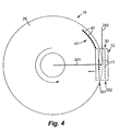
- Figure 4 is a plan view illustrating one embodiment of printing within a circular area according to the present invention.
- Figure 5A is a schematic illustration of one embodiment of an arcuate print pattern printed within a circular area according to the present invention.
- Figure 5B is a schematic illustration of another embodiment of an arcuate print pattern printed within a circular area according to the present invention.
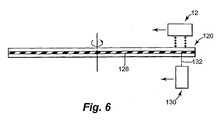
- Figure 6 is a schematic illustration of one embodiment of printing on and recording to an optical data storage disk according to the present invention.
- In the following detailed description, reference is made to the accompanying drawings which form a part hereof, and in which is shown by way of illustration specific embodiments in which the invention may be practiced. In this regard, directional terminology, such as "top," "bottom," "front," "back," "leading," "trailing," etc., is used with reference to the orientation of the Figure(s) being described. Because components of the present invention can be positioned in a number of different orientations, the directional terminology is used for purposes of illustration and is in no way limiting. It is to be understood that other embodiments may be utilized and structural or logical changes may be made without departing from the scope of the present invention. The following detailed description, therefore, is not to be taken in a limiting sense, and the scope of the present invention is defined by the appended claims.
- Figure 1 illustrates one embodiment of a portion of an
inkjet printing system 10.Inkjet printing system 10 includes aprinthead assembly 12, anink supply assembly 14, amounting assembly 16, amedia transport assembly 18, and anelectronic controller 20.Printhead assembly 12 includes one or more printheads which eject drops of ink, including one or more colored inks, through a plurality of orifices ornozzles 13. - In one embodiment, the drops of ink are directed toward a medium, such as a
print media 19, so as to print ontoprint media 19.Print media 19 includes any type of suitable sheet material, such as paper, card stock, envelopes, labels, transparencies, Mylar, and the like or other planar material such as an optical data storage disk, as described below. Typically,nozzles 13 are arranged in one or more columns or arrays such that properly sequenced ejection of ink fromnozzles 13 causes characters, symbols, and/or other graphics or images to be printed uponprint media 19 asprinthead assembly 12 andprint media 19 are moved relative to each other. -
Ink supply assembly 14 supplies ink toprinthead assembly 12 and includes areservoir 15 for storing ink. As such, in one embodiment, ink flows fromreservoir 15 toprinthead assembly 12. In one embodiment,printhead assembly 12 andink supply assembly 14 are housed together in an inkjet print cartridge or pen. In another embodiment,ink supply assembly 14 is separate fromprinthead assembly 12 and supplies ink toprinthead assembly 12 through an interface connection, such as a supply tube. -
Mounting assembly 16positions printhead assembly 12 relative tomedia transport assembly 18, andmedia transport assembly 18positions print media 19 relative toprinthead assembly 12. As such, aprint region 17 within whichprinthead assembly 12 deposits ink drops is defined adjacent tonozzles 13 in an area betweenprinthead assembly 12 andprint media 19. In one embodiment, as described below,print media 19 is rotated during printing bymedia transport assembly 18. -
Mounting assembly 16 typically includes a carriage and a carriage drive assembly. As such,printhead assembly 12 is removably mounted in, and supported by, the carriage, and the carriage drive assembly moves the carriage and, therefore,printhead assembly 12 relative toprint media 19. A conventional carriage drive assembly may include a carriage guide which supports the carriage, a drive motor, and a belt and pulley system which moves the carriage along the carriage guide. -
Electronic controller 20 communicates withprinthead assembly 12,mounting assembly 16, andmedia transport assembly 18.Electronic controller 20 receivesdata 21 from a host system, such as a computer, and includes memory for temporarily storingdata 21. Typically,data 21 is sent toinkjet printing system 10 along an electronic, infrared, optical or other information transfer path.Data 21 represents, for example, an image or graphics to be printed. As such,data 21 forms a print job forinkjet printing system 10 and includes one or more print job commands and/or command parameters. - In one embodiment,
electronic controller 20 provides control ofprinthead assembly 12 including timing control for ejection of ink drops fromnozzles 13. As such,electronic controller 20 defines a pattern of ejected ink drops which form characters, symbols, and/or other graphics or images onprint media 19. Timing control and, therefore, the pattern of ejected ink drops, is determined by the print job commands and/or command parameters. In one embodiment, logic and drive circuitry forming a portion ofelectronic controller 20 is located onprinthead assembly 12. In another embodiment, logic and drive circuitry is located offprinthead assembly 12. - In one embodiment, as illustrated in Figure 2,
print media 19 includes an opticaldata storage disk 120. Opticaldata storage disk 120 may include, for example, a compact disk (CD) media, a CD-recordable (CD-R) media, a CD-read only memory (CD-ROM) media, a CD-rewritable (CD-RW) media, a digital versatile disk or digital video disk (DVD) media, a DVD-random access memory (DVD-RAM) media, or any other type of writable optical media, such as a magneto-optical (MO) disk or phase-change optical disk. - Optical
data storage disk 120 includes acircular member 122 having a central bore or opening 124 formed therein. In one embodiment, opening 124 is sized to accommodate a drive pin or other engagement feature of an optical disk drive (not shown). As described below, opticaldata storage disk 120 includes a layer which may be read or written on by a recording head. - As illustrated in the embodiment of Figure 2, one side of optical
data storage disk 120 includes acircular area 126 which provides a printable area for opticaldata storage disk 120. As such,printhead assembly 12 prints graphics or images directly on opticaldata storage disk 120, as described below. In one embodiment,circular area 126 has an area for opening 124 of opticaldata storage disk 120. Thus, in one embodiment,circular area 126 is an annular area. - In one embodiment, as illustrated in Figure 3,
print media 19 includes alabel 220 for opticaldata storage disk 120. In one embodiment,label 220 includes acircular area 226. In one embodiment,circular area 226 is sized to fit opticaldata storage disk 120 and has an area for opening 124 of opticaldata storage disk 120. Thus, in one embodiment,circular area 226 is an annular area. - In one embodiment,
label 220 includes a backing material and a printable material removably adhered to the backing material. In one embodiment,label 220 is square with the inner and outer diameters ofcircular area 226 defined by concentriccircular slits Slits circular area 226 to be peeled off of the backing material, - In one embodiment, the printable material includes an adhesive layer such that the printable material and the backing material may be separated and the printable material may be adhered to optical
data storage disk 120. As such,printhead assembly 12 prints graphics or images onlabel 220, as described below, andlabel 220 is adhered to a side of opticaldata storage disk 120. - As illustrated in the embodiment of Figure 4,
nozzles 13 ofprinthead assembly 12 are arranged in one ormore columns 30. In one exemplary embodiment,nozzles 13 ofprinthead assembly 12 are arranged in two columns, including a first column 301 and a second column 302. In one embodiment, first column 301 and second column 302 are spaced from and oriented substantially parallel to each other. -
Printhead assembly 12 is positioned relative to print media 19 (including opticaldata storage disk 120 asprint media 19 orlabel 220 as print media 19) such that at least one column, for example, column 301 ofnozzles 13 is positioned in spaced relation from and above acircular area 26 ofprint media 19. For example, when opticaldata storage disk 120 constitutesprint media 19,circular area 126 of opticaldata storage disk 120 constitutescircular area 26, and whenlabel 220 constitutesprint media 19,circular area 226 oflabel 220 constitutescircular area 26. As such,print region 17 extends betweennozzles 13 andcircular area 26. - In one embodiment,
printhead assembly 12 is positioned relative toprint media 19 such thatcolumn 30 ofnozzles 13 is oriented substantially perpendicular to aradius 261 ofcircular area 26 ofprint media 19.Radius 261 is extended to a position of and/or belowprinthead assembly 12 such thatcolumn 30 ofnozzles 13 is oriented substantially perpendicular toradius 261 extended belowprinthead assembly 12. As such,printhead assembly 12 is oriented substantially parallel to a tangent 262 ofcircular area 26 atradius 261 ofcircular area 26. - In one embodiment,
print media 19 is rotated relative toprinthead assembly 12 during printing. Print media 19 (including opticaldata storage disk 120 asprint media 19 andlabel 220 as print media 19) is rotated, for example, by media transport assembly 18 (Figure 1). To rotateprint media 19,media transport assembly 18 may include, for example, a rotational member such as a spindle or platter which engages or supportsprint media 19 and a rotational motor which rotates the rotational member such that rotational motion of the motor is imparted toprint media 19 by the rotational member. - While
print media 19 is rotated,printhead assembly 12 creates anarcuate print pattern 40 withincircular area 26. More specifically,dots 42 are created onprint media 19 by ejecting ink throughnozzles 13 ofprinthead assembly 12.Dots 42 are printed along and follow an arc centered about a center ofcircular area 26 so as to createarcuate print pattern 40. Withcolumn 30 ofnozzles 13 oriented substantially perpendicular toradius 261 ofcircular area 26,arcuate print pattern 40 is created substantially perpendicular toradius 261 ofcircular area 26 asprint media 19 is rotated. - In one embodiment,
multiple nozzles 13 within one column ofprinthead assembly 12, for example, nozzles within column 301 simultaneously print dots onprint media 19 asprint media 19 rotates relative toprinthead assembly 12. As such, a speed at whichprint media 19 is rotated during printing can be increased. Thus, a speed at whicharcuate print pattern 40 is created can be increased. - As illustrated in the embodiment of Figure 4,
printhead assembly 12 andprint media 19 are moved relative to each other in a direction substantially parallel toradius 261 ofcircular area 26. In one embodiment,printhead assembly 12 is moved relative toprint media 19 alongradius 261 ofcircular area 26.Printhead assembly 12 is moved relative toprint media 19, for example, by mountingassembly 16. In another embodiment,print media 19 is moved relative toprinthead assembly 12 such thatprinthead assembly 12 followsradius 261 ofcircular area 26.Print media 19 is moved relative toprinthead assembly 12, for example, bymedia transport assembly 18, - in one embodiment,
printhead assembly 12 andprint media 19 are moved relative to each other so as to positionprinthead assembly 12 between an outer diameter and an inner diameter ofcircular area 26. Thus, by movingprinthead assembly 12 andprint media 19 relative to each other,arcuate print pattern 40 is created within a printable area and, more specifically, withincircular area 26 ofprint media 19. In one embodiment, as illustrated in Figure 5A,printhead assembly 12 andprint media 19 are moved relative to each other such thatarcuate print pattern 40 includesconcentric print patterns 401 formed withincircular area 26. In another embodiment, as illustrated in Figure 5B,printhead assembly 12 andprint media 19 are moved relative to each other such thatarcuate print pattern 40 includes aspiral print pattern 402 formed withincircular area 26. - It is understood that Figures 4, 5A, and 5B are simplified schematic illustrations of one embodiment of arcuate print pattern 40 (including
concentric print patterns 401 and spiral print pattern 402). In addition, while only one column ofnozzles 13 is illustrated as printingarcuate print pattern 40 in Figure 4, it is understood that multiple columns ofnozzles 13 may print respective arcuate print patterns withincircular area 26 ofprint media 19. - In one embodiment, as illustrated in Figure 6, optical
data storage disk 120 includes arecording layer 128. As such, arecording head 130 is positioned on a side of opticaldata storage disk 120 for recording digital data torecording layer 128.Recording head 130 records digital data torecording layer 128 by directing arecording beam 132, such as a laser beam, torecording layer 128 while opticaldata storage disk 120 rotates. As such,recording beam 132 creates marks or pits representing digital data inrecording layer 128. - It is understood that Figure 6 is a simplified schematic illustration of one embodiment of optical
data storage disk 120, includingrecording layer 128. For example, in addition torecording layer 128, opticaldata storage disk 120 may also include other layers, such as protective, reflective, and/or dielectric layers, formed on one or more sides of a substrate material. - As illustrated in the embodiment of Figure 6,
printhead assembly 12 is positioned on a first side of opticaldata storage disk 120 andrecording head 130 is positioned on a second side of opticaldata storage disk 120 opposite the first side. As such,printhead assembly 12 prints on opticaldata storage disk 120 from the first side andrecording head 130 records to opticaldata storage disk 120 from the second side as opticaldata storage disk 120 rotates relative toprinthead assembly 12 andrecording head 130. in one embodiment,printhead assembly 12 andrecording head 130 simultaneously print on and record to opticaldata storage disk 120. More specifically,printhead assembly 12 prints on opticaldata storage disk 120 from the first side andrecording head 130 records to opticaldata storage disk 120 from the second side as opticaldata storage disk 120 rotates at one predetermined speed. - As illustrated in the embodiment of Figure 6,
printhead assembly 12 andrecording head 130 move relative to opticaldata storage disk 120 while printing on and recording to opticaldata storage disk 120.Printhead assembly 12 andrecording head 130, for example, move between the outer diameter and the inner diameter of opticaldata storage disk 120 during printing and recording. In one embodiment,printhead assembly 12 andrecording head 130 each move relative to opticaldata storage disk 120 in a direction substantially parallel to a radius of opticaldata storage disk 120. - In one exemplary embodiment, as illustrated in Figure 6,
printhead assembly 12 andrecording head 130 print on and record to, respectively, opticaldata storage disk 120 while moving from the outer diameter toward the inner diameter of opticaldata storage disk 120. It is understood, however, thatprinthead assembly 12 and/orrecording head 130 may print on and record to, respectively, opticaldata storage disk 120 while moving from the inner diameter toward the outer diameter of opticaldata storage disk 120. - As described above, by positioning
printhead assembly 12 withnozzles 13 oriented substantially perpendicular toradius 261 ofcircular area 26, multiple nozzles can be operated in unison. As such, print speed can be increased. Thus, opticaldata storage disk 120 can be rotated at an increased speed when printing withincircular area 126 of opticaldata storage disk 120. Accordingly, in one embodiment, opticaldata storage disk 120 is rotated at one speed during printing and recording. in addition,printhead assembly 12 andrecording head 130 are moved relative to opticaldata storage disk 120 at the same speed. As such, printing and recording can be completed during the same time. - Although specific embodiments have been illustrated and described herein, it will be appreciated by those of ordinary skill in the art that a wide variety of alternate and/or equivalent implementations calculated to achieve the same purposes may be substituted for the specific embodiments shown and described without departing from the scope of the present invention. Those with skill in the chemical, mechanical, electro-mechanical, electrical, and computer arts will readily appreciate that the present invention may be implemented in a very wide variety of embodiments. This application is intended to cover any adaptations or variations of the specific embodiments discussed herein. Therefore, it is manifestly intended that this invention be limited only by the claims and the equivalents thereof.
Claims (26)
- A method of printing within a circular area (26) of a media (19), the method comprising:positioning a printhead (12) including at least one column (30) of nozzles (13) above the circular area of the media, including orienting the at least one column of nozzles substantially perpendicular to a radius (261) of the circular area extended below the printhead;rotating the media relative to the printhead; andprinting at least one arcuate print pattern (40) within the circular area of the media with the printhead while rotating the media.
- The method of claim 1, wherein positioning the printhead includes orienting the at least one column of nozzles substantially parallel to a tangent (262) of the circular area at the radius of the circular area.
- The method of claim 1, wherein printing the at least one arcuate print pattern includes printing the at least one arcuate print pattern along an arc centered about a center of the circular area of the media.
- The method of claim 1, wherein printing the at least one arcuate print pattern includes printing the at least one arcuate print pattern substantially perpendicular to the radius of the circular area of the media with the printhead while rotating the media.
- The method of claim 1, further comprising:moving the printhead and the media relative to each other in a direction substantially parallel to the radius of the circular area of the media.
- The method of claim 5, wherein moving the printhead and the media relative to each other includes moving the printhead along the radius of the circular area of the media.
- A system for printing within a circular area (26) of a media (19), the system comprising:a printhead (12) including at least one column (30) of nozzles (13), the at least one column of nozzles adapted to be oriented substantially perpendicular to a radius (261) of the circular area extended below the printhead; andan assembly (18) adapted to rotate the media relative to the printhead,wherein the printhead is adapted to print at least one arcuate print pattern (40) within the circular area of the media as the assembly rotates the media relative to the printhead.
- The system of claim 7, wherein the at least one column of nozzles are adapted to be oriented substantially parallel to a tangent (262) of the circular area at the radius of the circular area.
- The system of claim 7, wherein the at least one arcuate print pattern follows an arc centered about a center of the circular area of the media.
- The system of claim 7, wherein the printhead is adapted to print the at least one arcuate print pattern substantially perpendicular to the radius of the circular area of the media as the assembly rotates the media relative to the printhead.
- The system of claim 7, wherein the printhead is adapted to move relative to the media in a direction substantially parallel to the radius of the circular area of the media.
- The system of claim 7, wherein the printhead is adapted to move relative to the media along the radius of the circular area of the media.
- A method of printing on and recording to an optical data storage disk, the method comprising:positioning a printhead (12) adjacent a first side of the optical data storage disk, including orienting a column (30) of nozzles (13) of the printhead substantially perpendicular to a radius (261) of the optical data storage disk extended below the printhead;positioning a recording head (130) adjacent a second side of the optical data storage disk opposite the first side thereof;rotating the optical data storage disk relative to the printhead and the recording head;printing at least one arcuate print pattern (40) on the optical data storage disk with the printhead while rotating the optical data storage disk; andrecording to the optical data storage disk with the recording head while rotating the optical data storage disk.
- The method of claim 13, wherein positioning the printhead includes orienting the column of nozzles substantially parallel to a tangent (262) of the optical data storage disk at the radius of the optical data storage disk.
- The method of claim 13, wherein printing the at least one arcuate print pattern includes printing the at least one arcuate print pattern along an arc centered about a center of the optical data storage disk.
- The method of claim 13, wherein printing the at least one arcuate print pattern includes printing the at least one arcuate print pattern substantially perpendicular to the radius of the optical data storage disk with the printhead while rotating the optical data storage disk.
- The method of claim 13, wherein printing on the optical data storage disk and recording to the optical data storage disk includes simultaneously printing on the optical data storage disk and recording to the optical data storage disk.
- The method of claim 13, further comprising:moving the printhead and the optical data storage disk relative to each other and the recording head and the optical data storage disk relative to each other in a direction substantially parallel to the radius of the optical data storage disk.
- The method of claim 18, wherein moving the printhead and the optical data storage disk relative to each other includes moving the printhead along the radius of the optical data storage disk relative to the optical data storage disk.
- A system for printing on and recording to an optical data storage disk, the system comprising:a printhead (12) adapted to be positioned adjacent a first side of the optical data storage disk and including at least one column (30) of nozzles (13), the at least one column of nozzles adapted to be oriented substantially perpendicular to a radius (261) of the optical data storage disk extended below the printhead;a recording head (130)
adapted to be positioned adjacent a second side of the optical data storage disk opposite the first side thereof; andan assembly (18) adapted to rotate the optical data storage disk relative to the printhead and the recording head,wherein the printhead is adapted to print at least one arcuate print pattern (40) on the optical data storage disk as the assembly rotates the optical data storage disk relative to the printhead, and
wherein the recording head is adapted to record to the optical data storage disk as the assembly rotates the optical data storage disk relative to the recording head. - The system of claim 20, wherein the at least one column of nozzles are adapted to be oriented substantially parallel to a tangent (262) of the optical data storage disk at the radius of the optical data storage disk.
- The system of claim 20, wherein the at least one arcuate print pattern follows an arc centered about a center of the optical data storage disk.
- The system of claim 20, wherein the printhead is adapted to print the at least one arcuate print pattern substantially perpendicular to the radius of the optical data storage disk as the assembly rotates the optical data storage disk relative to the printhead.
- The system of claim 20, wherein the printhead and the recording head are adapted to simultaneously print on and record to the optical data storage disk.
- The system of claim 20, wherein the printhead and the recording head are each adapted to move relative to the optical data storage disk in a direction substantially parallel to the radius of the optical data storage disk.
- The system of claim 20, wherein the printhead is adapted to move relative to the optical data storage disk along the radius of the optical data storage disk.
Applications Claiming Priority (2)
| Application Number | Priority Date | Filing Date | Title |
|---|---|---|---|
| US607892 | 2000-06-30 | ||
| US10/607,892 US20040263561A1 (en) | 2003-06-27 | 2003-06-27 | System and method of printing within circular area |
Publications (2)
| Publication Number | Publication Date |
|---|---|
| EP1491345A2 true EP1491345A2 (en) | 2004-12-29 |
| EP1491345A3 EP1491345A3 (en) | 2006-05-31 |
Family
ID=33418724
Family Applications (1)
| Application Number | Title | Priority Date | Filing Date |
|---|---|---|---|
| EP04253606A Withdrawn EP1491345A3 (en) | 2003-06-27 | 2004-06-16 | System and method of printing within circular area |
Country Status (2)
| Country | Link |
|---|---|
| US (1) | US20040263561A1 (en) |
| EP (1) | EP1491345A3 (en) |
Families Citing this family (3)
| Publication number | Priority date | Publication date | Assignee | Title |
|---|---|---|---|---|
| JP5004328B2 (en) * | 2006-09-12 | 2012-08-22 | キヤノン株式会社 | Image recording apparatus, image recording method, and computer program |
| JP2010277647A (en) * | 2009-05-28 | 2010-12-09 | Sony Corp | Printing apparatus, printing method, and printing program |
| JP5407844B2 (en) | 2009-12-24 | 2014-02-05 | ブラザー工業株式会社 | Inkjet recording apparatus and inkjet recording method |
Family Cites Families (11)
| Publication number | Priority date | Publication date | Assignee | Title |
|---|---|---|---|---|
| US4613916A (en) * | 1983-12-30 | 1986-09-23 | International Business Machines Corporation | Information storage disk transducer position control system requiring no servo pattern on the storage disk |
| DE3721651A1 (en) * | 1987-07-01 | 1989-01-12 | Philips & Du Pont Optical | METHOD FOR PRINTING DISK-SHAPED INFORMATION CARRIERS |
| JP3341572B2 (en) * | 1996-03-27 | 2002-11-05 | セイコーエプソン株式会社 | Optical disk drive |
| US5949688A (en) * | 1996-06-27 | 1999-09-07 | Montoya; Shauna Renee | Compact disc recorder/vending machine |
| US6019151A (en) * | 1997-01-07 | 2000-02-01 | Eastman Kodak Company | Printing onto discs such as compact discs and the like |
| US6264295B1 (en) * | 1998-04-17 | 2001-07-24 | Elesys, Inc. | Radial printing system and methods |
| US7085017B1 (en) * | 2001-08-03 | 2006-08-01 | Elesys, Inc. | Polar halftone methods for radial printing |
| US6910750B2 (en) * | 2000-06-02 | 2005-06-28 | Elesys, Inc. | Low-profile ink head cartridge with integrated movement mechanism and service station |
| US6736475B2 (en) * | 2000-03-21 | 2004-05-18 | Elesys, Inc. | Method for providing angular position information for a radial printing system |
| IL127317A0 (en) * | 1998-11-29 | 1999-09-22 | Ink Jet Technology | Printing mechanism for digital discs |
| US6202550B1 (en) * | 1998-12-30 | 2001-03-20 | Eastman Kodak Company | Printer and method for printing indicia on a compact disk using a plurality of ink jet or laser rotatable print heads |
-
2003
- 2003-06-27 US US10/607,892 patent/US20040263561A1/en not_active Abandoned
-
2004
- 2004-06-16 EP EP04253606A patent/EP1491345A3/en not_active Withdrawn
Also Published As
| Publication number | Publication date |
|---|---|
| US20040263561A1 (en) | 2004-12-30 |
| EP1491345A3 (en) | 2006-05-31 |
Similar Documents
| Publication | Publication Date | Title |
|---|---|---|
| US6771297B2 (en) | Labeling apparatus and method for disk storage media | |
| EP1018433B1 (en) | Printer for printing on a disk and method of assembling the printer | |
| US6074031A (en) | Method and apparatus for printing labels on digital recording media | |
| JPH09265760A (en) | Optical disk drive | |
| WO1999030481A2 (en) | Apparatus and methods for printing labels on optical media | |
| WO2000032399A1 (en) | Printing mechanism for digital discs | |
| US7036131B2 (en) | Printing optical disc player/recorder | |
| JP4793239B2 (en) | Printing apparatus, printing method, and recording medium driving apparatus | |
| US8537652B2 (en) | Optical recording/reproducing apparatus having label printer and method for printing labels on optical disk | |
| EP1491345A2 (en) | System and method of printing within circular area | |
| JP2004110994A (en) | Optical information recording / reading and optical disk label surface printing device | |
| JP2008027535A (en) | Printing apparatus and printing method | |
| JP2008137297A (en) | Printing method, printing apparatus, and recording medium driving apparatus | |
| JP2002324380A (en) | Optical disk system | |
| US7561309B2 (en) | Recording apparatus and recording method | |
| JPH0611562B2 (en) | Inkjet recording device | |
| US20060221102A1 (en) | Recording apparatus | |
| JP2008018609A (en) | Printing apparatus and recording medium driving apparatus | |
| JP2006331534A (en) | Media processing device | |
| JP2008027534A (en) | Printing apparatus and printing method | |
| JP2007172741A (en) | Disk drive apparatus | |
| KR100789863B1 (en) | Optical disc drive unit for label printing of optical discs | |
| JP2006306051A (en) | Recorder | |
| JPH06198890A (en) | Ink-jet type recording device | |
| JP2008103038A (en) | Optical disk duplicating device |
Legal Events
| Date | Code | Title | Description |
|---|---|---|---|
| PUAI | Public reference made under article 153(3) epc to a published international application that has entered the european phase |
Free format text: ORIGINAL CODE: 0009012 |
|
| AK | Designated contracting states |
Kind code of ref document: A2 Designated state(s): AT BE BG CH CY CZ DE DK EE ES FI FR GB GR HU IE IT LI LU MC NL PL PT RO SE SI SK TR |
|
| AX | Request for extension of the european patent |
Extension state: AL HR LT LV MK |
|
| RIN1 | Information on inventor provided before grant (corrected) |
Inventor name: SERRA, JOSEP-MARIA Inventor name: BUIBAS, MARIUS Inventor name: THIESSEN, KURT |
|
| PUAL | Search report despatched |
Free format text: ORIGINAL CODE: 0009013 |
|
| AK | Designated contracting states |
Kind code of ref document: A3 Designated state(s): AT BE BG CH CY CZ DE DK EE ES FI FR GB GR HU IE IT LI LU MC NL PL PT RO SE SI SK TR |
|
| AX | Request for extension of the european patent |
Extension state: AL HR LT LV MK |
|
| 17P | Request for examination filed |
Effective date: 20061110 |
|
| AKX | Designation fees paid |
Designated state(s): DE GB NL |
|
| STAA | Information on the status of an ep patent application or granted ep patent |
Free format text: STATUS: THE APPLICATION HAS BEEN WITHDRAWN |
|
| 18W | Application withdrawn |
Effective date: 20080509 |