EP1491161B1 - Biegsame Welle - Google Patents
Biegsame Welle Download PDFInfo
- Publication number
- EP1491161B1 EP1491161B1 EP04011398.7A EP04011398A EP1491161B1 EP 1491161 B1 EP1491161 B1 EP 1491161B1 EP 04011398 A EP04011398 A EP 04011398A EP 1491161 B1 EP1491161 B1 EP 1491161B1
- Authority
- EP
- European Patent Office
- Prior art keywords
- flexible shaft
- wall
- section
- shaft
- cell
- Prior art date
- Legal status (The legal status is an assumption and is not a legal conclusion. Google has not performed a legal analysis and makes no representation as to the accuracy of the status listed.)
- Expired - Lifetime
Links
Images


Classifications
-
- A—HUMAN NECESSITIES
- A61—MEDICAL OR VETERINARY SCIENCE; HYGIENE
- A61F—FILTERS IMPLANTABLE INTO BLOOD VESSELS; PROSTHESES; DEVICES PROVIDING PATENCY TO, OR PREVENTING COLLAPSING OF, TUBULAR STRUCTURES OF THE BODY, e.g. STENTS; ORTHOPAEDIC, NURSING OR CONTRACEPTIVE DEVICES; FOMENTATION; TREATMENT OR PROTECTION OF EYES OR EARS; BANDAGES, DRESSINGS OR ABSORBENT PADS; FIRST-AID KITS
- A61F2/00—Filters implantable into blood vessels; Prostheses, i.e. artificial substitutes or replacements for parts of the body; Appliances for connecting them with the body; Devices providing patency to, or preventing collapsing of, tubular structures of the body, e.g. stents
- A61F2/82—Devices providing patency to, or preventing collapsing of, tubular structures of the body, e.g. stents
- A61F2/86—Stents in a form characterised by the wire-like elements; Stents in the form characterised by a net-like or mesh-like structure
- A61F2/90—Stents in a form characterised by the wire-like elements; Stents in the form characterised by a net-like or mesh-like structure characterised by a net-like or mesh-like structure
- A61F2/91—Stents in a form characterised by the wire-like elements; Stents in the form characterised by a net-like or mesh-like structure characterised by a net-like or mesh-like structure made from perforated sheets or tubes, e.g. perforated by laser cuts or etched holes
- A61F2/915—Stents in a form characterised by the wire-like elements; Stents in the form characterised by a net-like or mesh-like structure characterised by a net-like or mesh-like structure made from perforated sheets or tubes, e.g. perforated by laser cuts or etched holes with bands having a meander structure, adjacent bands being connected to each other
-
- A—HUMAN NECESSITIES
- A61—MEDICAL OR VETERINARY SCIENCE; HYGIENE
- A61F—FILTERS IMPLANTABLE INTO BLOOD VESSELS; PROSTHESES; DEVICES PROVIDING PATENCY TO, OR PREVENTING COLLAPSING OF, TUBULAR STRUCTURES OF THE BODY, e.g. STENTS; ORTHOPAEDIC, NURSING OR CONTRACEPTIVE DEVICES; FOMENTATION; TREATMENT OR PROTECTION OF EYES OR EARS; BANDAGES, DRESSINGS OR ABSORBENT PADS; FIRST-AID KITS
- A61F2/00—Filters implantable into blood vessels; Prostheses, i.e. artificial substitutes or replacements for parts of the body; Appliances for connecting them with the body; Devices providing patency to, or preventing collapsing of, tubular structures of the body, e.g. stents
- A61F2/82—Devices providing patency to, or preventing collapsing of, tubular structures of the body, e.g. stents
- A61F2/86—Stents in a form characterised by the wire-like elements; Stents in the form characterised by a net-like or mesh-like structure
- A61F2/90—Stents in a form characterised by the wire-like elements; Stents in the form characterised by a net-like or mesh-like structure characterised by a net-like or mesh-like structure
- A61F2/91—Stents in a form characterised by the wire-like elements; Stents in the form characterised by a net-like or mesh-like structure characterised by a net-like or mesh-like structure made from perforated sheets or tubes, e.g. perforated by laser cuts or etched holes
-
- A—HUMAN NECESSITIES
- A61—MEDICAL OR VETERINARY SCIENCE; HYGIENE
- A61F—FILTERS IMPLANTABLE INTO BLOOD VESSELS; PROSTHESES; DEVICES PROVIDING PATENCY TO, OR PREVENTING COLLAPSING OF, TUBULAR STRUCTURES OF THE BODY, e.g. STENTS; ORTHOPAEDIC, NURSING OR CONTRACEPTIVE DEVICES; FOMENTATION; TREATMENT OR PROTECTION OF EYES OR EARS; BANDAGES, DRESSINGS OR ABSORBENT PADS; FIRST-AID KITS
- A61F2/00—Filters implantable into blood vessels; Prostheses, i.e. artificial substitutes or replacements for parts of the body; Appliances for connecting them with the body; Devices providing patency to, or preventing collapsing of, tubular structures of the body, e.g. stents
- A61F2/82—Devices providing patency to, or preventing collapsing of, tubular structures of the body, e.g. stents
- A61F2/86—Stents in a form characterised by the wire-like elements; Stents in the form characterised by a net-like or mesh-like structure
- A61F2/90—Stents in a form characterised by the wire-like elements; Stents in the form characterised by a net-like or mesh-like structure characterised by a net-like or mesh-like structure
- A61F2/91—Stents in a form characterised by the wire-like elements; Stents in the form characterised by a net-like or mesh-like structure characterised by a net-like or mesh-like structure made from perforated sheets or tubes, e.g. perforated by laser cuts or etched holes
- A61F2/915—Stents in a form characterised by the wire-like elements; Stents in the form characterised by a net-like or mesh-like structure characterised by a net-like or mesh-like structure made from perforated sheets or tubes, e.g. perforated by laser cuts or etched holes with bands having a meander structure, adjacent bands being connected to each other
- A61F2002/91516—Stents in a form characterised by the wire-like elements; Stents in the form characterised by a net-like or mesh-like structure characterised by a net-like or mesh-like structure made from perforated sheets or tubes, e.g. perforated by laser cuts or etched holes with bands having a meander structure, adjacent bands being connected to each other the meander having a change in frequency along the band
-
- A—HUMAN NECESSITIES
- A61—MEDICAL OR VETERINARY SCIENCE; HYGIENE
- A61F—FILTERS IMPLANTABLE INTO BLOOD VESSELS; PROSTHESES; DEVICES PROVIDING PATENCY TO, OR PREVENTING COLLAPSING OF, TUBULAR STRUCTURES OF THE BODY, e.g. STENTS; ORTHOPAEDIC, NURSING OR CONTRACEPTIVE DEVICES; FOMENTATION; TREATMENT OR PROTECTION OF EYES OR EARS; BANDAGES, DRESSINGS OR ABSORBENT PADS; FIRST-AID KITS
- A61F2/00—Filters implantable into blood vessels; Prostheses, i.e. artificial substitutes or replacements for parts of the body; Appliances for connecting them with the body; Devices providing patency to, or preventing collapsing of, tubular structures of the body, e.g. stents
- A61F2/82—Devices providing patency to, or preventing collapsing of, tubular structures of the body, e.g. stents
- A61F2/86—Stents in a form characterised by the wire-like elements; Stents in the form characterised by a net-like or mesh-like structure
- A61F2/90—Stents in a form characterised by the wire-like elements; Stents in the form characterised by a net-like or mesh-like structure characterised by a net-like or mesh-like structure
- A61F2/91—Stents in a form characterised by the wire-like elements; Stents in the form characterised by a net-like or mesh-like structure characterised by a net-like or mesh-like structure made from perforated sheets or tubes, e.g. perforated by laser cuts or etched holes
- A61F2/915—Stents in a form characterised by the wire-like elements; Stents in the form characterised by a net-like or mesh-like structure characterised by a net-like or mesh-like structure made from perforated sheets or tubes, e.g. perforated by laser cuts or etched holes with bands having a meander structure, adjacent bands being connected to each other
- A61F2002/91533—Stents in a form characterised by the wire-like elements; Stents in the form characterised by a net-like or mesh-like structure characterised by a net-like or mesh-like structure made from perforated sheets or tubes, e.g. perforated by laser cuts or etched holes with bands having a meander structure, adjacent bands being connected to each other characterised by the phase between adjacent bands
- A61F2002/91541—Adjacent bands are arranged out of phase
-
- A—HUMAN NECESSITIES
- A61—MEDICAL OR VETERINARY SCIENCE; HYGIENE
- A61F—FILTERS IMPLANTABLE INTO BLOOD VESSELS; PROSTHESES; DEVICES PROVIDING PATENCY TO, OR PREVENTING COLLAPSING OF, TUBULAR STRUCTURES OF THE BODY, e.g. STENTS; ORTHOPAEDIC, NURSING OR CONTRACEPTIVE DEVICES; FOMENTATION; TREATMENT OR PROTECTION OF EYES OR EARS; BANDAGES, DRESSINGS OR ABSORBENT PADS; FIRST-AID KITS
- A61F2/00—Filters implantable into blood vessels; Prostheses, i.e. artificial substitutes or replacements for parts of the body; Appliances for connecting them with the body; Devices providing patency to, or preventing collapsing of, tubular structures of the body, e.g. stents
- A61F2/82—Devices providing patency to, or preventing collapsing of, tubular structures of the body, e.g. stents
- A61F2/86—Stents in a form characterised by the wire-like elements; Stents in the form characterised by a net-like or mesh-like structure
- A61F2/90—Stents in a form characterised by the wire-like elements; Stents in the form characterised by a net-like or mesh-like structure characterised by a net-like or mesh-like structure
- A61F2/91—Stents in a form characterised by the wire-like elements; Stents in the form characterised by a net-like or mesh-like structure characterised by a net-like or mesh-like structure made from perforated sheets or tubes, e.g. perforated by laser cuts or etched holes
- A61F2/915—Stents in a form characterised by the wire-like elements; Stents in the form characterised by a net-like or mesh-like structure characterised by a net-like or mesh-like structure made from perforated sheets or tubes, e.g. perforated by laser cuts or etched holes with bands having a meander structure, adjacent bands being connected to each other
- A61F2002/9155—Adjacent bands being connected to each other
Definitions
- the invention relates to a flexible shaft for insertion into a channel of a living body and its preferred use, with a plurality of adjacent cells whose walls are each formed of wall sections.
- the invention relates to a flexible shaft which is suitable for insertion into a lumen or a channel with different properties.
- Such different properties of lumens may be different curvatures, side branches, variable diameters, or different compliant lumen walls.
- Flexible shafts of the above type are used, for example, to stents in various channels of living body, such as. Blood vessels, esophagus, urethra, kidney ducts, introduce.
- the stent must be radially expanded after insertion, using a rod passed through the interior of the flexible shaft.
- the flexible shaft must be designed tube-like and also adapted to curved or curved channel or wire areas.
- WO 99/44543 A describes improved stent cell configurations in which the cells have three or more enlarged end portions for radiating from a common center within the cell.
- the object of the invention is to provide a flexible shaft for insertion into a lumen of a living body, which is inexpensive to manufacture and at the same time has a high flexibility coupled with sufficient stability, in particular for supporting a rod for expanding a stent.
- This object is achieved by a flexible shaft according to claim 1. preferred Embodiments are subject of the dependent claims.
- the object is achieved according to the invention with a shaft mentioned above, in at least one cell in cross section considered the wall is formed in the circumferential direction alternately from a respective concave wall portion and an adjacent convex wall portion.
- the wall is formed in the circumferential direction successively from concave and convex wall sections. In this way, a plurality of regions are formed in the wall, on each of which an initially folded concave and an adjacent convex wall section are stretched or unfolded on bending or deformation of the flexible shaft on each cell.
- the stretching of the folded concave and convex wall sections results in a simultaneous enlargement of the single cell at several areas of the wall.
- the simultaneous stretching or unfolding of the wall at a plurality of regions causes the wall of the individual cell to be deformed into a plurality of directional components, in particular more than two directional components, during the bending or deformation.
- the shaft of the invention is not compressed in bending in the radial direction, so that a guided in the flexible shaft rod is not clamped.
- the inner diameter is slightly increased during bending or deformation, since the stretching walls of deformed cells increasingly push in the direction of a radial expansion of the shaft.
- the stretching process of the walls propagates beyond the cells.
- the expansion of a cell in the wall of the flexible shaft according to the invention in this way leads to a uniform deformation in a larger area of the wall structure. Unwanted, localized and therefore structurally weakening deformations are inventively avoided.
- the wall of a shaft according to the invention over the circumference relatively evenly folded or formed corrugated.
- a coating of the wall, for example with a lubricant is therefore easier to train.
- the wall of a cell of a shaft according to the invention is formed solely of curved or folded wall regions and junctions against which such wall regions abut one another.
- the shaft according to the invention does not shorten in the axial direction during deformation. Rather, a wave according to the invention is characterized by a uniform expansion of the cell structure in several directions.
- the shaft according to the invention can also be expanded particularly homogeneously and shrunk again. This advantage can be used if the shaft is to be manufactured in the expanded or partially expanded state. Furthermore, this advantage can be used in methods of electropolishing and coating. The shaft can be stretched before the process and subsequently compressed again evenly. The quality of the surfaces achieved by the process can be increased in this way.
- the crosslinking according to the invention and the formation of different deformation directions is, as already mentioned, particularly advantageous when bending an expanded shaft.
- the cells of a wave according to the invention deform uniformly expanding or upsetting depending on the position of the bending line and thus allow a homogeneous bending of the shaft.
- the invention is particularly useful with stainless steel, tantalum, niobium, cobalt alloy and other materials such as stainless steel shafts.
- Polymers self-degradable materials (e.g., lactic acid materials or derivatives), as well as nitinol (nickel-titanium alloy) shafts, and / or other self-expanding materials.
- At least one convex wall section is formed with a radius of curvature that is substantially equal to a radius of curvature of an adjacent concave wall section.
- Substantially equal radii of curvature on the folded wall of the cells result in a particularly uniform structure of the shaft.
- Such a wave can therefore be electrochemically polished or coated particularly well.
- coating or coating processes are facilitated because shading effects in the so-called PVD or CVD process are avoided or reduced and / or drop effects during immersion processes (which occur due to capillary action of narrow radii) are avoided.
- a further developed wave is constructed of identical geometry elements except for nodes.
- the geometry elements can have identical outside and inside diameters and identical structure widths. From such geometric elements is formed by various types of nesting a base element in the form of a cell.
- the wall section can advantageously be designed in each case in the form of a circular arc or as a circular arc or circular structure. Voltage peaks in the material of the shaft can be avoided in this way and a torsion of the shaft is facilitated.
- At least one cell is designed in each case from at least three convex wall sections, in each of which a concave wall section is formed between two convex wall sections.
- Such a single cell of a shaft according to the invention is stretched in three mutually non-parallel directions when expanding. The directions are each offset in particular by an angle of 120 °.
- the flexible shaft according to the invention thus has a multiaxial deformation component and, in contrast to known waves having only two directional components offset by an angle of 90 °, is uniformly expanded in a particularly simple manner, as already explained above.
- the shaft according to the invention can be compressed particularly small and at the same time easily and uniformly deformed by the convex wall sections of at least one cell are formed adjacent to each other when viewed in cross-section in the compressed state of the shaft.
- the individual concave and convex wall portions according to the invention may be formed by various shapes. These formations can be circular-arc-shaped in cross-section or in particular have short straight sections.
- the basic idea is that the wall of a cell of the flexible shaft is formed by a juxtaposition of concave and convex wall sections, which may be formed in particular similar.
- the individual wall sections can advantageously be constructed from one and the same basic geometric element. These basic elements can be connected by nodes, the outer shape of which in turn is advantageously adapted to the outer shape of a basic element.
- the so-shaped flexible shaft is particularly advantageous both in terms of their achievable surface quality and thus their biocompatibility and the required production technology.
- the shaft is typically subjected to surface finishing, such as electrochemical polishing, which preferably produces a thin, protective oxide film on the surface.
- electrochemical polishing preferably produces a thin, protective oxide film on the surface.
- Such a method is based on a targeted mass removal of the surface of the shaft.
- the electropolished surface has very low roughness and high purity.
- the polishing process is carried out with the aid of electricity in an acid mixture, it being necessary for a uniform polishing, field-related, a component structure that is as homogeneous as possible to be present.
- the shaft according to the invention consists of such a particularly homogeneous structure. Particularly large or small radii on the structure are avoided according to the invention.
- known shafts consist of different structural components which have only been optimized with regard to the mechanical properties of the respective shaft.
- the flexible shaft can also be used on a guide wire body.
- the flexible shaft forms a highly flexible tip or a highly flexible distal end of the guide wire.
- the flexible wave structure i. H. the flexible shaft
- the flexible shaft may have a high torsional stiffness, so that it can be more easily inserted into tightly wound and small vessels. This is particularly advantageous when probing neurovascular blood vessels, such as the vertebral aorta, the aortic cerebralis or the aorta carotid.
- the flexible shaft can be used as a joint-free body or as a joint-free end in a controllable endoscope head. Since the shaft receives its flexibility through the continuous wall sections, additional connecting elements in the shaft structure, such as contact pins, etc., which make a relative movement relative to the body of the flexible shaft, are not necessary. This advantageously makes it possible to create a substantially maintenance-free component which can be used in an endoscope.
- the flexible shaft could form a rotating or rotatable drive shaft.
- a drive shaft is provided, which has a multi-axis freedom of movement, that is in a unidirectional manner is movable.
- a continuous bending or bending is possible, in addition, a rotational movement between two off-axis points can be transmitted.
- an off-axis compensating flexible drive shaft or clutch may be proposed.
- a flexible shaft or bending shaft has a multiplicity of cells 26 arranged at least in regions, which permits at least local bending or deformation of the flexible shaft, for example for adaptation to a shape of a body lumen or channel.
- one or more cells 26 are expanded and / or one or more cells 26 are compressed, resulting in a bend in the flexible one Wave is possible.
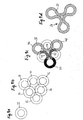
- Fig. 1a to 1d is the basic construction of a preferred cell 26 (see Fig. 1d ) which, combined with other cells, forms a bendable area between two non-flexible end portions of a flexible shaft 28 (see Figs Fig. 6 ).
- the cell 26 has a wall 30 composed of individual wall sections.
- a circular ring 32 As a basic element for the individual wall sections is in each case a circular ring 32, as in Fig. 1a is illustrated.
- the wall of annulus 38 covers the walls of annuli 34 and 40.
- the wall of annulus 40 covers the walls of annuli 38 and 42 and contacts the walls of annuli 34 and 36.
- the wall of annulus 42 covers the walls of annuli 36 and 40 ,
- Fig. 1c It is shown how the wall sections of the wall 30 of a single cell 26 are constructed from the circular rings 32 to 42 arranged in this way.
- the wall 30 is designed as a serpentine line in the form of a cross-section of respective concave and convex wall sections which alternate in the circumferential direction of the wall 30 or are arranged alternately and will be explained in greater detail below.
- the wall 30 has three "corner areas", each formed of a concave wall portion 44, 46 and 48.
- the wall sections 44, 46 and 48 are preferably circular arc-shaped and in each case form part of the circular rings 32, 38 and 42, respectively Fig. 1b represents.
- convex wall portions 50, 52 and 54 are formed, which come from the circular rings 34, 36 and 40, respectively.
- these wall sections preferably each contact the wall sections 50 and 52, 52 and 54 and 50 and 54 in the fully compressed state of a cell 30, as in Fig. 1c is shown.
- the wall sections 50, 52 and 54 need not necessarily touch. It is also possible states in which the cell 30 is only partially compressed and the wall portions 50, 52 and 54 are at least slightly spaced.
- the "folded" wall 30 is a cell 26 as shown in FIG Fig. 1d is composed, as a whole, of the concave and convex wall portions 44 to 54, respectively.
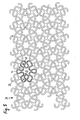
- the flexible shaft 28 is composed of a plurality of cells 26 abutting each other. In the Fig. 1d illustrated cell 26 is thus reflected in a flexible shaft 28, as in Fig. 2b and Fig. 6 is shown.
- the individual wall sections 44 to 54 of a cell 26 also belong at the same time as wall sections to adjacent cells. This circumstance is in the Fig. 2a to 2c illustrated.
- Fig. 2b shows that the walls 30 of a flexible shaft 28 can be considered in principle as a structured structure of many arcs 56, which are arranged between nodes or connecting elements 58. From a node 58 are each three arcs 56 from.
- the single circular arc 56 extends over an angular range between 160 ° and 180 °, in particular over an angular range of about 170 °. It is designed circular in cross-section on its inside and outside, so that its surfaces represent parts of circular cylindrical surfaces.
- the wall of the single circular arc 56 preferably has a constant thickness.
- the individual nodes 58 each connect three such circular arcs 56.
- the nodes 58 each have three sides or end regions, to each of which a circular arc 56 connects. Between each of the three end regions, a concave curve 58 'is formed at the nodes 58, whose radius substantially coincides with the inner radius of a circular arc 56. The curves of the circular arcs 56 thus pass smoothly into the adjacent curves 58 'of nodes 58, to which circular arcs 56 in turn follow. The curvature of the surface at the transition is constant.
- the curves 58 'of the nodes 58 and the inner surfaces of the circular arcs 56 belong to the concave wall regions 50, 52 and 54 described above.
- the convex wall sections 44, 46 or 48 are formed by the outer surfaces of the circular arcs 56. Therefore, inflection points of the curvature are present at the transitions between circular arcs 56 and node 58 where a convex wall section 44, 46 or 48 adjoins a node 58, ie where a concave wall section merges into an adjacent convex wall section.
- In 3 and 4 is illustrated as a flexible shaft 28 from its compressed or undeformed position according to Fig. 2c is converted into a partially expanded or curved structure.
- the three individual portions of the wall 30, each formed of a convex and the two adjacent concave wall sections deploy outward in three directions 60, 62 and 64. Between these directions 60, 62 and 64 each has an angle of 120 °.
- a cell area of the flexible shaft thus formed uniformly expands in the directions 60, 62 and 64, whereby the advantages mentioned above in connection with the invention are achieved.
- FIG. 5 A second exemplary embodiment of a flexible shaft 28 is illustrated, in which multiply folded wall regions 68 are formed between nodes or connecting elements 66.
- the multiply folded wall portions 68 are each individually formed from three substantially semicircular arcs 70, 72 and 74, which successively form in the designated cell 26 a convex, a concave and a further convex wall portion. In an adjacent cell, these arcs simultaneously form a concave, a convex and a further concave wall section.
- the individual sheets 70, 72 and 74 span an angle of about 150 ° to 250 °, preferably of about 200 °. Their surfaces essentially correspond to a section of a circular cylinder. The thickness of the wall of the sheets 70, 72 and 74 is substantially constant.
- the nodes 66 have four sides or end regions, to each of which a wall portion 68 connects. Concave curves 66 ', whose radius corresponds in each case to the inner radius of an arc 70, 72 or 74, are located between these end regions. A single node 66 is thus designed in cross-section substantially cross-shaped. The transition between a node 66 and a bow 70, 72 or 74 is smooth and designed without an edge. The curvature of the surface at the transition is in turn substantially constant. The individual concave curves 66 'at the nodes 66 each extend over an angle of approximately 70 ° to 110 °, preferably over an angle of approximately 90 °.
- the wall 30 of a cell 26 of the flexible shaft 28 is all formed of alternating concave and convex wall sections, each of which individually follows the basic shape of a circular arc or a circular ring when viewed in cross-section. From a node 66 are each four such wall portions 68 from.
- the structure of flexible shaft according to Fig. 5 leads to a simultaneous expansion preferably in four directions. Conceivable, however, are also flexible waves with a "spider-like" shape, in which cells are provided at least partially, all of which are formed of alternating concave and convex wall sections and whose nodes protrude five or more wall areas.
- the production of the flexible shaft according to the invention or a preferred embodiment thereof can be carried out both from raw material and from flat material, wherein in the latter the flexible shaft is later rolled, welded and / or finished. Furthermore, the production of the flexible shaft by means of laser cutting, laser ablation, photochemical etching and / or erosion done. Furthermore, the production of the flexible shaft can also be such that the flexible shaft structure is made in an at least partially expanded form and the flexible shaft is subsequently reduced to a compressed shape before it subsequently bent upon insertion into a body and thereby at least partially expanded becomes.
- the flexible shaft is used for arranging insertion of a spreader structure into a hollow organ having spreader bars extending from a first connecting portion substantially in a longitudinal direction of the spreader structure to a second connecting portion over which Scope of the spreading structure are arranged distributed and can be applied by radial spreading to a wall of the hollow organ.
- Spreader structures of the above type may be preferably used with the aid of the flexible shaft as implants for a limited period or permanently in a hollow organ, such as heart, blood vessels, biliary tract, urinary tract, gastrointestinal tract, uterus and brain ventricles For example, to retain thrombi or bile duct stones.
- a hollow organ such as heart, blood vessels, biliary tract, urinary tract, gastrointestinal tract, uterus and brain ventricles
- various types of thrombosis filters are known, which are inserted percutaneously as a venous implant via the femoral vein or the jugular vein into the inferior vena cava or the superior vena cava.
- thrombi on their way to the heart and thereby prevent a pulmonary embolism.
- Such implants are usually designed with tapered struts or rods that form a funnel-shaped filter basket.
- the flexible shaft can be used for arranging a metal electrode in order to introduce heat to a wall of the hollow organ and carry out
- the flexible shaft can advantageously be used for arranging or inserting (preferably self-expanding) endoprostheses for keeping awkward structures, which are also used as so-called stents in blood vessels.
- Stents are usually designed with a tubular, more or less fine-meshed wire mesh or wire mesh, which is radially expandable under an elastic restoring force of its wires.
- the flexible shaft is advantageously designed substantially tubular and inside a likewise flexible expansion shaft or rod or tube can be arranged, by means of which or the manipulated the spreading structure or the metal electrode or the stent (eg expanded and / or can be contracted or reduced in the outer circumference), in particular by means of relative displacement or displacement of the expansion shaft relative to the tubular shaft.
- a likewise flexible expansion shaft or rod or tube can be arranged, by means of which or the manipulated the spreading structure or the metal electrode or the stent (eg expanded and / or can be contracted or reduced in the outer circumference), in particular by means of relative displacement or displacement of the expansion shaft relative to the tubular shaft.
Landscapes
- Health & Medical Sciences (AREA)
- Engineering & Computer Science (AREA)
- Biomedical Technology (AREA)
- Heart & Thoracic Surgery (AREA)
- Life Sciences & Earth Sciences (AREA)
- Cardiology (AREA)
- Oral & Maxillofacial Surgery (AREA)
- Transplantation (AREA)
- Physics & Mathematics (AREA)
- Vascular Medicine (AREA)
- Optics & Photonics (AREA)
- Animal Behavior & Ethology (AREA)
- General Health & Medical Sciences (AREA)
- Public Health (AREA)
- Veterinary Medicine (AREA)
- Prostheses (AREA)
- Media Introduction/Drainage Providing Device (AREA)
Description
- Die Erfindung betrifft eine biegsame Welle zum Einführen in einen Kanal eines lebenden Körper sowie deren bevorzugte Verwendung, mit einer Vielzahl von aneinander angrenzenden Zellen, deren Wände je aus Wandabschnitten ausgebildet sind. Insbesondere betrifft die Erfindung eine biegsame Welle, die zum Einführen in ein Lumen bzw. einen Kanal mit unterschiedlichen Eigenschaften geeignet ist. Solche unterschiedlichen Eigenschaften von Lumen können verschiedene Krümmungen, Seitenverzweigungen, variable Durchmesser oder verschieden nachgiebige Lumenwände sein.
- Biegsame Wellen der oben genannten Art werden verwendet, um beispielsweise Stents in verschiedene Kanäle lebender Körper, wie z.B. Blutgefäße, Speiseröhre, Harnröhre, Nierengänge, einzuführen. Der Stent muß nach dem Einführen radial expandiert werden, wobei ein Stab bzw. eine Seele verwendet wird, die durch das Innere der biegsamen Welle hindurch geleitet ist. Zu diesem Zweck muß die biegsame Welle schlauchartig gestaltet sein und sich auch gebogenen bzw. kurvigen Kanal- bzw. Aderbereichen anpassen.
-
WO 99/44543 A - Aufgabe der Erfindung ist es, eine biegsame Welle zum Einführen in ein Lumen eines lebenden Körpers zu schaffen, die kostengünstig herzustellen ist und dabei zugleich eine hohe Flexibilität gepaart mit einer ausreichenden Stabilität, insbesondere zum Abstützen eines Stabes zum Expandieren eines Stents aufweist. Diese Aufgabe wird erfindungsgemäß durch eine biegsame Welle gemäß Anspruch 1 gelöst. Bevorzugte Ausführungsformen sind Gegenstand der Unteransprüche.
- Dementsprechend ist die Aufgabe erfindungsgemäß mit einer eingangs genannten Welle gelöst, bei der bei mindestens einer Zelle im Querschnitt betrachtet die Wand in Umfangsrichtung abwechselnd aus jeweils einem konkaven Wandabschnitt und einem benachbarten konvexen Wandabschnitt ausgebildet ist. Vorteilhafte Weiterbildungen der Erfindung sind in den Unteransprüchen beschrieben.
- Bei der erfindungsgemäßen biegsamen Welle ist die Wand in Umfangsrichtung aufeinanderfolgend aus konkaven und konvexen Wandabschnitten ausgebildet. Auf diese Weise sind in der Wand mehrere Bereiche gebildet, an denen beim Biegen bzw. Verformen der biegsamen Welle an jeder Zelle je ein zunächst gefalteter konkaver und ein benachbarter konvexer Wandabschnitt gestreckt bzw. entfaltet werden. Das Strecken der gefalteten konkaven und konvexen Wandabschnitte führt zu einer gleichzeitigen Vergrößerung der einzelnen Zelle an mehreren Bereichen der Wand.
- Das gleichzeitige Strecken bzw. Entfalten der Wand an mehreren Bereichen bewirkt, daß während des Biegens bzw. Verformens die Wand der einzelnen Zelle in mehrere Richtungskomponenten, insbesondere mehr als zwei Richtungskomponenten verformt wird. Die erfindungsgemäße Welle wird beim Biegen jedoch nicht in radialer Richtung komprimiert, so daß ein in der biegsamen Welle geführter Stab nicht geklemmt wird.
- Bei der erfindungsgemäßen Welle wird beim Biegen bzw. Verformen eher der innere Durchmesser leicht vergrößert, da die sich streckenden Wände von verformten Zellen verstärkt in Richtung auf eine radiale Expansion der Welle drängen.
- Erfindungsgemäß pflanzt sich ferner der Streckvorgang der Wände über die Zellen hinweg fort. Die Expansion einer Zelle in der Wand der erfindungsgemäßen biegsamen Welle führt auf diese Weise zu einer gleichmäßigen Verformung in einem größeren Bereich der Wandstruktur. Unerwünschte, lokal begrenzte und daher strukturschwächende Verformungen sind hingegen erfindungsgemäß vermieden.
- Bei Wegnahme der Deformationsbelastung an einer erfindungsgemäßen Welle stoppt deren Deformation nahezu schlagartig, ohne daß hohe Eigenspannungen in der Welle verbleiben würden.
- Darüber hinaus ist die Wand einer erfindungsgemäßen Welle über den Umfang hinweg verhältnismäßig gleichmäßig gefaltet bzw. gewellt ausgebildet. Eine Beschichtung der Wand, beispielsweise mit einem Gleitmittel ist daher einfacher auszubilden.
- Aufgrund der gleichmäßig gewellten Ausformung der Wand sind erfindungsgemäß Spannungsspitzen und lokale Deformationsspitzen in der biegsamen Welle vermieden. Weiterhin werden enge Radien bzw. die Ausbildung unterschiedlicher Radien vorteilhaft vermieden. Dadurch ist die Gefahr eines Beschädigens oder Abplatzens insbesondere einer metallischen oder keramischen Beschichtung der Wände der erfindungsgemäßen Welle vermieden. Ferner wird dadurch die Gefahr einer Materialüberbelastung durch Spannungsspitzen reduziert. Die Materialeigenschaften des jeweils eingesetzten Werkstoffs werden erfindungsgemäß besser ausgenutzt.
- Bei einer biegsamen Welle erhöht sich unter bestimmten Bedingungen bei zunehmender Verformung die Festigkeit des Materials der Welle. Dieser sogenannte Verfestigungseffekt kann erfindungsgemäß besonders gut ausgenutzt werden, weil die Wände der Welle gleichmäßig und zugleich in verhältnismäßig geringem Ausmaß verformt werden. Die Verformung zur Verfestigung des Materials kann erfindungsgemäß also sehr genau gesteuert werden und ist darüber hinaus über die gesamte Welle hinweg nahezu gleich ausgeprägt.
- Gemäß der Erfindung ist die Wand einer Zelle einer erfindungsgemäßen Welle allein aus gewölbten bzw. gefalteten Wandbereichen und Knotenpunkten ausgebildet, an denen solche Wandbereiche aneinanderstoßen.
- Darüber hinaus verkürzt sich die erfindungsgemäße Welle beim Verformen nicht in axialer Richtung. Eine Welle gemäß der Erfindung zeichnet sich vielmehr durch ein gleichmäßiges Aufdehnen der Zellenstruktur in mehrere Richtungen aus.
- Die erfindungsgemäße Welle kann ferner besonders homogen expandiert und wieder geschrumpft werden. Dieser Vorteil kann genutzt werden, wenn die Welle im expandierten oder teilexpandierten Zustand gefertigt werden soll. Weiterhin kann dieser Vorteil bei Verfahren der Elektropolitur und der Beschichtung genutzt werden. Die Welle kann vor dem Verfahren gestreckt und nachfolgend wieder gleichmäßig komprimiert werden. Die Qualität der durch das Verfahren erzielten Oberflächen kann auf diese Weise erhöht werden.
- Die erfindungsgemäße Vernetzung und Ausbildung unterschiedlicher Deformationsrichtungen ist, wie bereits erwähnt, besonders beim Biegen einer expandierten Welle von Vorteil. Die Zellen einer erfindungsgemäßen Welle verformen sich je nach Lage der Biegelinie gleichmäßig expandierend oder stauchend und ermöglichen so eine homogene Biegung der Welle.
- Die Erfindung kann besonders sinnvoll bei Wellen aus rostfreiem Edelstahl, Tantal, Niob, Kobaltlegierungen und anderen Werkstoffen wie z.B. Polymeren, selbstabbaubaren Werkstoffen (z.B. Milchsäure-Werkstoffen bzw. -Derivate), sowie bei Wellen aus Nitinol (Nickel-Titan-Legierungen) und/oder aus anderen selbstexpandierbaren Werkstoffen bzw. Formgedächniswerkstoffen verwendet werden.
- Bei einer vorteilhaften Weiterbildung der Erfindung ist im Querschnitt betrachtet mindestens ein konvexer Wandabschnitt mit einem Krümmungsradius ausgebildet, der im wesentlichen gleich einem Krümmungsradius eines benachbarten konkaven Wandabschnitts gestaltet ist. Im wesentlichen gleiche Krümmungsradien an der gefalteten Wand der Zellen führen zu einer besonders gleichmäßigen Struktur der Welle. Eine solche Welle kann daher besonders gut elektrochemisch poliert oder beschichtet werden. Ferner werden Coating- bzw. Beschichtungsvorgänge erleichtert, weil Abschattungseffekte beim sogenannten PVD- oder CVD-Verfahren vermieden bzw. vermindert und/oder Tropfeneffekte bei Tauchverfahren (die durch Kapillarwirkung enger Radien zustandekommen) vermieden werden.
- Die genannten Vorteile einer erfindungsgemäßen biegsamen Welle können weiter vorteilhaft ausgeprägt werden, indem im Querschnitt betrachtet die Wandabschnitte jeweils gleichartig oder fast gleichartig ausgebildet sind. Eine derartige weitergebildete Welle ist bis auf Knotenpunkte insgesamt aus gleichen Geometrieelementen aufgebaut. Die Geometrieelemente können identische Außen- und Innendurchmesser und identische Strukturbreiten aufweisen. Aus solchen Geometrielementen ist durch verschiedenartige Verschachtelung ein Basiselement in Gestalt einer Zelle gebildet.
- Darüber hinaus können im Querschnitt betrachtet die Wandabschnitt vorteilhaft jeweils kreisbogenförmig bzw. als Kreisbogen- bzw. Kreisstruktur ausgestaltet sein. Spannungsspitzen im Material der Welle können auf diese Art und Weise vermieden werden und eine Torsion der Welle wird erleichtert.
- Ferner ist es vorteilhaft, wenn im Querschnitt betrachtet mindestens eine Zelle je aus mindestens drei konvexen Wandabschnitten gestaltet ist, bei denen jeweils zwischen zwei konvexen Wandabschnitten ein konkaver Wandabschnitt ausgebildet ist. Eine derartige einzelne Zelle einer erfindungsgemäßen Welle wird beim Expandieren in drei zueinander nicht parallelen Richtungen gestreckt. Die Richtungen sind insbesondere jeweils um einen Winkel von 120° versetzt. Die erfindungsgemäße biegsame Welle besitzt damit eine mehrachsige Deformationskomponente und wird im Gegensatz zu bekannten Wellen, die nur zwei um einen Winkel von 90° versetzte Richtungskomponenten aufweisen, in besonders einfacher Weise gleichmäßig expandiert, wie oben bereits erläutert wurde.
- Die erfindungsgemäße Welle kann besonders klein komprimiert und zugleich leicht und gleichmäßig verformt werden, indem im Querschnitt betrachtet bei komprimiertem Zustand der Welle die konvexen Wandabschnitte mindestens einer Zelle aneinander anliegend ausgebildet sind.
- Gemäß der Erfindung können darüber hinaus die oben als vorteilhaft beschriebenen und in den Unteransprüchen dargelegten Weiterbildungen der Erfindung auch ohne die im Anspruch 1 genannten Merkmale als einzelne Gegenstände oder in Kombination untereinander selbständig schutzwürdig sein.
- Es sei noch angemerkt, daß die einzelnen konkaven und konvexen Wandabschnitte gemäß der Erfindung durch verschiedenartige Ausformungen gebildet sein können. Diese Ausformungen können im Querschnitt kreisbogenförmig sein oder insbesondere kurze gerade Abschnitte aufweisen. Grundgedanke ist es, daß die Wand einer Zelle der biegsamen Welle durch eine Aneinanderreihung von konkaven und konvexen Wandabschnitten gebildet ist, die insbesondere gleichartig ausgebildet sein können. Die einzelnen Wandabschnitte können vorteilhaft aus ein und demselben geometrischen Grundelement aufgebaut sein. Diese Grundelemente können durch Knotenpunkte verbunden sein, deren äußere Gestalt insbesondere vorteilhaft wiederum an die äußere Form eines Grundelements angepaßt ist.
- Die derart gestaltete biegsame Welle ist sowohl hinsichtlich ihrer erzielbaren Oberflächenqualität und damit auch ihrer Biokompatibilität als auch der erforderlichen Fertigungstechnik besonders vorteilhaft. Zur Erzielung einer besonders guten Biokompatibilität wird die Welle in der Regel einer Oberflächenveredelung, wie etwa einer elektrochemischen Politur, unterzogen, welche bevorzugt einen dünnen, schützenden Oxidfilm auf der Oberfläche produziert. Ein solches Verfahren beruht auf einem gezielten Masseabtrag der Oberfläche der Welle. Die elektropolierte Oberfläche besitzt sehr geringe Rauhigkeit und eine hohe Reinheit. Das Polierverfahren wird stromunterstützt in einem Säuregemisch durchgeführt, wobei für eine gleichmäßige Politur, feldbedingt, eine möglichst homogene Bauteilstruktur vorhanden sein muß. Die erfindungsgemäße Welle besteht, wie oben erläutert worden ist, aus einer solchen, besonders homogenen Struktur. Besonders große oder kleine Radien an der Struktur sind erfindungsgemäß vermieden. Bekannte Wellen bestehen hingegen aus unterschiedlichen konstruktiven Komponenten, die lediglich hinsichtlich der mechanischen Eigenschaften der jeweiligen Welle optimiert wurden.
- Gemäß der Erfindung wird eine Verwendung einer biegsamen Welle nach der Erfindung oder einer bevorzugt Ausführungsform hiervon bereitgestellt zum Einführen zum Einführen bzw. Anordnen von einer Spreizstruktur, einer Metallelektrode und/oder einer Endoprothesen bzw. Stent in ein Hohlorgan bzw. Lumen bzw. Kanal bzw. Hohlraum.
- Weiterhin kann die biegsame Welle in einer vorteilhaften Ausführungsform ebenfalls an einem Führungsdrahtkörper verwendet werden. Hierbei bildet die biegsame Welle eine hochflexible Spitze bzw. ein hochflexibles distales Ende des Führungsdrahts aus. Somit kann eine optimale Zuführbarkeit ins Zielgebiet sichergestellt werde, da die biegsame Wellenstruktur, d. h. die biegsame Welle, stufenlos und ohne Einschränkungen ähnlich eines gummielastischen Schlauchs abgebogen bzw. abgewinkelt werden kann. Insbesondere kann die biegsame Welle eine hohe Torsionssteifigkeit aufweisen, so dass diese leichter in eng gewundene und kleine Gefäße eingeführt werden kann. Dies ist insbesondere vorteilhaft beim Sondieren von neurovaskulären Blutgefäßen, wie beispielsweise der Aorta vertebralis, der Aorta cerebralis oder der Aorta carotis.
- Besonders vorteilhafterweise kann die biegsame Welle als gelenkfreier Körper bzw. als gelenkfreies Ende in einem steuerbaren Endoskopkopf verwendet werden. Da durch die zusammenhängenden Wandabschnitte die Welle ihre Biegsamkeit erhält, sind zusätzliche Verbindungselemente in der Wellenstruktur, wie Kontaktstifte etc. auf, welche gegenüber dem Körper der biegsamen Welle eine Relativbewegung ausführen, nicht notwendig. Hierdurch lässt sich vorteilhafterweise ein im wesentlichen wartungsfreies Bauteil schaffen, welches in einem Endoskop eingesetzt werden kann.
- In einer weiteren Ausführungsform könnte die biegsame Welle eine rotierende bzw. rotierbare Antriebswelle ausbilden. Somit wird eine Antriebswelle vorgesehen, welche eine mehrachsige Bewegungsfreiheit aufweist, also in unidirektionaler weise beweglich ist. Hierbei ist eine stufenlose Biegung bzw. Abwinklung möglich, wobei zusätzlich eine Rotationsbewegung zwischen zwei achsversetzten Punkten übertragen werden kann. Somit kann vorteilhafterweise wird eine achsversatz-kompensierende flexible Antriebswelle bzw. -kupplung vorgeschlagen werden.
- Nachfolgend werden Ausführungsbeispiele einer erfindungsgemäßen Welle anhand der beigefügten schematischen Zeichnungen näher erläutert. Es zeigen:
- Fig. 1a bis 1d
- eine Abfolge von Graphiken zur Veranschaulichung des Aufbaus einer Zelle eines ersten Ausführungsbeispiels einer erfindungsgemäßen biegsamen Welle,
- Fig. 2a bis 2c
- eine Abfolge von Graphiken zur Veranschaulichung des Aufbaus einer Struktur aus Zellen des ersten Ausführungsbeispiels einer erfindungsgemäßen biegsamen Welle,
- Fig. 3
- einen Querschnitt des ersten Ausführungsbeispiels einer erfindungsgemäßen biegsamen Welle an einem komprimierten Strukturabschnitt,
- Fig. 4
- einen Querschnitt des ersten Ausführungsbeispiels einer erfindungsgemäßen biegsamen Welle an einem expandierten Strukturabschnitt,
- Fig. 5
- einen Querschnitt eines zweiten Ausführungsbeispiels einer erfindungsgemäßen biegsamen Welle an einem komprimierten Strukturabschnitt, und
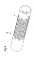
- Fig. 6
- eine perspektivische Ansicht des ersten Ausführungsbeispiels einer erfindungsgemäßen biegsamen Welle im nicht verformten bzw. komprimierten Zustand.
- Gemäß einer bevorzugten Ausführungsform der Erfindung weist eine biegsame Welle bzw. Biegewelle eine Vielzahl von zumindest bereichsweise angeordneten Zellen 26, welche eine zumindest lokale Biegung bzw. Verformung der biegsamen Welle z.B. zur Anpassung an eine Form eines Körper-Lumens bzw. -Kanals ermöglicht. Bei einer Biegung bzw. Verformung der biegsamen Welle werden ein oder mehrere Zellen 26 expandiert und/oder ein oder mehrere Zellen 26 komprimiert, so daß im Ergebnis eine Biegung bzw. Verformung der biegsamen Welle möglich ist.
- In den
Fig. 1a bis 1d ist der Grundaufbau einer bevorzugten Zelle 26 (sieheFig. 1d ) veranschaulicht, die kombiniert mit weiteren Zellen einen biegsamen Bereich zwischen zwei nicht biegsamen Endbereichen eine biegsame Welle 28 (sieheFig. 6 ) bildet. Die Zelle 26 weist eine Wand 30 auf, die aus einzelnen Wandabschnitten zusammengesetzt ist. - Als Grundelement für die einzelnen Wandabschnitte dient jeweils ein Kreisring 32, wie er in
Fig. 1a veranschaulicht ist. - An einen solchen Kreisring 32 sind gedanklich zwei weitere Kreisringe 34 und 36 angelegt. Die Wände der angelegten Kreisringe 34 und 36 berühren sich und überdecken jeweils die Wand des ersten Kreisrings 32.
- An die Kreisringe 34 und 36 sind wiederum gedanklich drei Kreisringe 38, 40 und 42 angelegt. Die Wand des Kreisrings 38 überdeckt die Wände der Kreisringe 34 und 40. Die Wand des Kreisrings 40 überdeckt die Wände der Kreisringe 38 und 42 und berührt die Wände der Kreisringe 34 und 36. Die Wand des Kreisrings 42 überdeckt die Wände der Kreisringe 36 und 40.
- Insgesamt sind auf diese Weise sechs Kreisringe zu einem Dreieck zusammengesetzt, wobei sich die Wände der Kreisringe im äußeren Bereich des Dreiecks jeweils überdecken und sich im Zentralbereich des Dreiecks jeweils berühren (siehe
Fig. 1b ). - In
Fig. 1c ist dargestellt, wie aus den derart angeordneten Kreisringen 32 bis 42 die Wandabschnitte der Wand 30 einer einzelnen Zelle 26 aufgebaut sind. - Die Wand 30 ist grundsätzlich im Querschnitt betrachtet schlangenlinienförmig aus jeweils konkaven und konvexen Wandabschnitten gestaltet, die sich in Umfangsrichtung der Wand 30 abwechseln bzw. alternierend angeordnet sind und nachfolgend genauer erläutert werden.
- Gemäß der Grundstruktur des Dreiecks der
Fig. 1b weist auch die Wand 30 drei "Eckbereiche" auf, die jeweils aus einem konkaven Wandabschnitt 44, 46 und 48 gebildet sind. Die Wandabschnitte 44, 46 und 48 sind bevorzugt kreisbogenförmig und stellen jeweils einen Teil der Kreisringe 32, 38 bzw. 42 gemäßFig. 1b dar. - Zwischen den konkaven Wandabschnitten 44, 46 und 48 sind jeweils konvexe Wandabschnitte 50, 52 und 54 ausgebildet, die von den Kreisringen 34, 36 bzw. 40 stammen. Von diesen Wandabschnitten berühren sich bevorzugt jeweils die Wandabschnitte 50 und 52, 52 und 54 sowie 50 und 54 im vollständig komprimierten Zustand einer Zelle 30, wie er in
Fig. 1c dargestellt ist. Im komprimierten Zustand einer Zelle 30 müssen sich die Wandabschnitte 50, 52 und 54 aber nicht zwingend berühren. Es sind auch Zustände möglich, bei denen die Zelle 30 nur teilweise komprimiert ist und die Wandabschnitte 50, 52 und 54 zumindest geringfügig beabstandet sind. - Demnach ist die "gefaltete" Wand 30 einer Zelle 26, wie sie in
Fig. 1d veranschaulicht ist, insgesamt aus den konkaven bzw. konvexen Wandabschnitten 44 bis 54 zusammengesetzt. - Die biegsame Welle 28 ist aus einer Vielzahl Zellen 26 aufgebaut, die aneinander anliegen. Die in
Fig. 1d veranschaulichte Zelle 26 findet sich so in einer biegsamen Welle 28 wieder, wie sie inFig. 2b undFig. 6 gezeigt ist. - Aufgrund der Kombination der Zellen 26 zu einer biegsamen Wellenstruktur gehören die einzelnen Wandabschnitte 44 bis 54 einer Zelle 26 auch zugleich als Wandabschnitte zu benachbarten Zellen. Dieser Umstand ist in den
Fig. 2a bis 2c veranschaulicht. - Die Graphik gemäß
Fig. 2b zeigt, daß die Wände 30 einer biegsamen Welle 28 grundsätzlich auch als strukturierter Aufbau aus vielen Kreisbögen 56 betrachtet werden kann, die zwischen Knoten bzw. Verbindungselementen 58 angeordnet sind. Von einem Knoten 58 stehen dabei jeweils drei Kreisbögen 56 ab. - Der einzelne Kreisbogen 56 erstreckt sich über einen Winkelbereich zwischen 160° und 180°, insbesondere über einen Winkelbereich von etwa 170°. Er ist an seiner Innenseite und seiner Außenseite jeweils im Querschnitt kreisförmig gestaltet, so daß seine Oberflächen Teile von Kreiszylinderflächen darstellen. Die Wand des einzelnen Kreisbogens 56 weist bevorzugt eine konstante Dicke auf. Die einzelnen Knoten 58 verbinden jeweils drei solcher Kreisbögen 56.
- Die Knoten 58 weisen jeweils drei Seiten bzw. Endbereiche auf, an denen jeweils ein Kreisbogen 56 anschließt. Zwischen den drei Endbereichen ist an den Knoten 58 jeweils eine konkave Rundung 58' ausgebildet, deren Radius mit dem inneren Radius eines Kreisbogens 56 im wesentlichen übereinstimmt. Die Rundungen der Kreisbögen 56 gehen also glatt in die benachbarten Rundungen 58' von Knoten 58 über, an die sich wiederum Kreisbögen 56 anschließen. Die Krümmung der Oberfläche am Übergang ist konstant.
- Die Rundungen 58' der Knoten 58 und die inneren Oberflächen der Kreisbögen 56 gehören zu den oben beschriebenen konkaven Wandbereichen 50, 52 und 54. Die konvexen Wandabschnitte 44, 46 oder 48 werden von den äußeren Oberflächen der Kreisbögen 56 gebildet. An den Übergängen zwischen Kreisbögen 56 und Knoten 58 sind daher jeweils dort Wendepunkte der Krümmung vorhanden, wo an einen Knoten 58 ein konvexer Wandabschnitt 44, 46 oder 48 grenzt, wo also ein konkaver Wandabschnitt in einen benachbarten konvexen Wandabschnitt übergeht.
- In
Fig. 3 und 4 ist veranschaulicht, wie eine biegsame Welle 28 aus ihrer komprimierten bzw. unverformten Stellung gemäßFig. 2c in eine teilweise expandierte bzw. gebogene Struktur übergeführt wird. Beim Biegen der Welle bzw. abschnittsweisen Expandieren von Zellen der Welle entfalten sich die drei einzelnen Bereiche der Wand 30, die jeweils aus einem konvexen und den beiden benachbarten konkaven Wandabschnitten gebildet sind, nach außen in drei Richtungen 60, 62 und 64. Zwischen diesen Richtungen 60, 62 und 64 besteht jeweils ein Winkel von 120°. - Wie insbesondere in
Fig. 4 veranschaulicht ist, expandiert ein Zellenbereich der derart gestalteten biegsamen Welle gleichmäßig in die Richtungen 60, 62 und 64, wodurch die oben im Zusammenhang mit der Erfindung genannten Vorteile erzielt werden. - In
Fig. 5 ist ein zweites Ausführungsbeispiel einer biegsamen Welle 28 veranschaulicht, bei der zwischen Knoten bzw. Verbindungselementen 66 mehrfach gefaltete Wandbereiche 68 ausgebildet sind. Die mehrfach gefalteten Wandbereiche 68 sind je einzeln aus drei im wesentlichen halbkreisförmigen Bögen 70, 72 und 74 gestaltet, die in der bezeichneten Zelle 26 aufeinanderfolgend einen konvexen, einen konkaven und einen weiteren konvexen Wandabschnitt bilden. In einer benachbarten Zelle bilden diese Bögen zugleich einen konkaven, einen konvexen und einen weiteren konkaven Wandabschnitt. - Die einzelnen Bögen 70, 72 und 74 überspannen einen Winkel von etwa 150° bis 250°, bevorzugt von zirka 200°. Ihre Oberflächen entsprechen im wesentlichen einem Abschnitt eines Kreiszylinders. Die Dicke der Wand der Bögen 70, 72 und 74 ist im wesentlichen konstant.
- Die Knoten 66 weisen vier Seiten bzw. Endbereiche auf, an denen jeweils ein Wandabschnitt 68 anschließt. Zwischen diesen Endbereichen befinden sich konkave Rundungen 66', deren Radius jeweils dem inneren Radius eines Bogens 70, 72 oder 74 entspricht. Ein einzelner Knoten 66 ist somit im Querschnitt betrachtet im wesentlichen kreuzförmig gestaltet. Der Übergang zwischen einem Knoten 66 und einem Bogen 70, 72 oder 74 ist fließend bzw. glatt und ohne eine Kante gestaltet. Die Krümmung der Oberfläche am Übergang ist wiederum im wesentlichen konstant. Die einzelnen konkaven Rundungen 66' an den Knoten 66 erstrecken sich jeweils über einen Winkel von ca. 70° bis 110°, bevorzugt über einen Winkel von etwa 90°.
- Auch bei dem Ausführungsbeispiel gemäß
Fig. 5 ist die Wand 30 einer Zelle 26 der biegsamen Welle 28 demnach sämtlich aus abwechselnd konkaven und konvexen Wandabschnitten ausgebildet, die im Querschnitt betrachtet einzeln jeweils der Grundform eines Kreisbogens bzw. eines Kreisrings folgen. Von einem Knoten 66 stehen jeweils vier solcher Wandbereiche 68 ab. Die Struktur der biegsamen Welle gemäßFig. 5 führt zu einer gleichzeitigen Expansion bevorzugt in vier Richtungen. Denkbar sind jedoch auch biegsame Wellen mit einer "spinnenartigen" Gestalt, in denen zumindest teilweise Zellen vorgesehen sind, die sämtlich aus abwechselnd konkaven und konvexen Wandabschnitten ausgebildet und deren Knoten fünft oder mehr Wandbereiche abstehen. - Die Herstellung der biegsamen Welle gemäß der Erfindung oder einer bevorzugten Ausführungsform hiervon kann sowohl aus Rohmaterial als auch aus Flachmaterial erfolgen, wobei bei letzterem die biegsame Welle später gerollt, geschweißt und/oder endbearbeitet wird. Weiterhin kann die Herstellung der biegsamen Welle mittels Laserschneiden, Laserabtrag, photochemisches Ätzen und/oder Erodieren erfolgen. Weiterhin kann die Herstellung der biegsamen Welle auch derart erfolgen, daß die biegsame Wellenstruktur in einer zumindest teilweise expandierten Form gefertigt wird und die biegsame Welle anschließend auf eine komprimierte Form verkleinert wird, bevor sie nachfolgend beim Einführen in einen Körper gebogen und dabei wieder zumindest teilweise expandiert wird.
- Gemäß einer bevorzugten Ausführungsform der Erfindung wird die biegsame Welle zum Anordnen bzw. Einführen von einer Spreizstruktur in ein Hohlorgan verwendet, welche Spreizstäbe aufweist, die sich ausgehend von einem ersten Verbindungsabschnitt im Wesentlichen in einer Längsrichtung der Spreizstruktur bis zu einem zweiten Verbindungsabschnitt erstrecken, über den Umfang der Spreizstruktur verteilt angeordnet sind und durch radiales Aufspreizen an eine Wand des Hohlorgans anlegbar sind.
- Spreizstrukturen der oben genannten Art können bevorzugt mit Hilfe der biegsamen Welle als Implantate für einen begrenzten Zeitraum oder auf Dauer in ein Hohlorgan, wie beispielsweise Herz, Blutgefäße, Gallenwege, ableitende Harnwege, Magen-Darm-Trakt, Uterus und Hirnventrikel, eingesetzt werden, um beispielsweise Thromben oder Gallengangssteine zurückzuhalten. So sind verschiedene Arten von Thrombosefilter bekannt, die als Venenimplantat perkutan über die Vena femoralis oder die Vena jugularis in die Vena cava inferior oder die Vena cava superior eingeführt werden. Dort soll das Venenimplantat Thromben auf ihrem Weg zum Herzen zurückhalten und dadurch einer Lungenembolie vorbeugen. Solche Implantate sind in der Regel mit konisch verlaufenden Streben oder Stäben gestaltet, die einen trichterförmigen Filterkorb bilden. Weiterhin kann die biegsame Welle zum Anordnen einer Metallelektrode verwendet werden, um an einer Wand des Hohlorgans Wärme einzubringen und dort beispielsweise eine Elektrokoagulation durchzuführen.
- Ferner kann die biegsame Welle vorteilhaft zum Anordnen bzw. Einsezen von (bevorzugt selbstexpandierende) Endoprothesen zum Offenhalten von gangartigen Strukturen verwendet werden, die als sogenannte Stents auch in Blutgefäßen zum Einsatz kommen. Stents sind in der Regel mit einem schlauchförmigen, mehr oder weniger feinmaschigen Drahtgewebe oder Drahtgeflecht gestaltet, das unter einer elastischen Rückstellkraft seiner Drähte radial expandierbar ist.
- Für derartige Verwendungen ist die biegsame Welle vorteilhaft im wesentlichen rohrförmig ausgestaltet und im Inneren kann eine ebenfalls biegsame Spreizwelle bzw. -stab bzw. -rohr angeordnet sein, mittels derer bzw. deren die Spreizstruktur bzw. die Metallelektrode bzw. der Stent manipuliert (z.B. expandiert und/oder kontrahiert bzw. im Außenumfang verkleinert werden kann), insbesondere mittels relativer Verschiebung bzw. Verlagerung der Spreizwelle gegenüber der rohrförmigen Welle.
-
- 26
- Zelle
- 28
- biegsame Welle
- 30
- Wand
- 32
- Kreisring
- 34
- Kreisring
- 36
- Kreisring
- 38
- Kreisring
- 40
- Kreisring
- 42
- Kreisring
- 44
- konkaver Wandabschnitt
- 46
- konkaver Wandabschnitt
- 48
- konkaver Wandabschnitt
- 50
- konvexer Wandabschnitt
- 52
- konvexer Wandabschnitt
- 54
- konvexer Wandabschnitt
- 56
- Kreisbogen
- 58
- Knoten
- 58'
- Rundung
- 60
- erste Richtung
- 62
- zweite Richtung
- 64
- dritte Richtung
- 66
- Knoten
- 66'
- Rundung
- 68
- gefalteter Wandbereich
- 70
- Bogen
- 72
- Bogen
- 74
- Bogen
Claims (7)
- Biegsame Welle (28) zum Einführen von medizinischen Produkten wie Stents in einen Kanal eines lebenden Körpers, insbesondere intraluminale, biegsame Welle, mit einer Vielzahl von aneinander angrenzenden Zellen (26), deren Wände (30) je aus Wandabschnitten ausgebildet sind, wobei bei mindestens einer Zelle (26) im Querschnitt betrachtet die Wand (30) in Umfangsrichtung abwechselnd aus jeweils einem konkaven Wandabschnitt (44, 46, 48) und einem benachbarten konvexen Wandabschnitt (50, 52, 54) ausgebildet ist, so dass eine zumindest lokale Biegung bzw. Verformung der biegsamen Welle möglich ist.
- Biegsame Welle nach Anspruch 1,
dadurch gekennzeichnet, daß im Querschnitt betrachtet mindestens ein konvexer Wandabschnitt (50, 52, 54) mit einem Krümmungsradius ausgebildet ist, der im wesentlichen gleich einem Krümmungsradius eines benachbarten konkaven Wandabschnitts (44, 46, 48) gestaltet ist. - Biegsame Welle nach Anspruch 1 oder 2,
dadurch gekennzeichnet, daß im Querschnitt betrachtet die Wandabschnitte (44, 46, 48, 50, 52, 54) jeweils gleichartig oder fast gleichartig ausgebildet sind. - Biegsame Welle nach einem der Ansprüche 1 bis 3,
dadurch gekennzeichnet, daß im Querschnitt betrachtet die Wandabschnitt (44, 46, 48, 50, 52, 54) jeweils kreisbogenförmig ausgestaltet sind. - Biegsame Welle nach einem der Ansprüche 1 bis 4,
dadurch gekennzeichnet, daß im Querschnitt betrachtet mindestens eine Zelle (26) je aus mindestens drei konvexen Wandabschnitten (50, 52, 54) gestaltet ist, bei denen jeweils zwischen zwei konvexen Wandabschnitten (50, 52, 54) ein konkaver Wandabschnitt (44, 46, 48) ausgebildet ist. - Biegsame Welle nach einem der Ansprüche 1 bis 5,
dadurch gekennzeichnet, daß im Querschnitt betrachtet bei einem nicht verformten bzw. komprimierten Zustand der Zellen (26) der biegsamen Welle (28) die konvexen Wandabschnitte (50, 52, 54) mindestens einer Zelle (26) aneinaner anliegend ausgebildet sind. - Biegsame Welle nach einem der Ansprüche 1 bis 6,
dadurch gekennzeichnet, daß eine Gleitbeschichtung an der Oberfläche der biegsamen Welle angeordnet ist.
Applications Claiming Priority (2)
| Application Number | Priority Date | Filing Date | Title |
|---|---|---|---|
| DE10328882A DE10328882B4 (de) | 2003-06-26 | 2003-06-26 | Verwendung einer biegsamen Welle als schlauchartige Einführvorrichtung |
| DE10328882 | 2003-06-26 |
Publications (2)
| Publication Number | Publication Date |
|---|---|
| EP1491161A1 EP1491161A1 (de) | 2004-12-29 |
| EP1491161B1 true EP1491161B1 (de) | 2015-04-15 |
Family
ID=33395004
Family Applications (1)
| Application Number | Title | Priority Date | Filing Date |
|---|---|---|---|
| EP04011398.7A Expired - Lifetime EP1491161B1 (de) | 2003-06-26 | 2004-05-13 | Biegsame Welle |
Country Status (3)
| Country | Link |
|---|---|
| US (1) | US8216293B2 (de) |
| EP (1) | EP1491161B1 (de) |
| DE (1) | DE10328882B4 (de) |
Families Citing this family (4)
| Publication number | Priority date | Publication date | Assignee | Title |
|---|---|---|---|---|
| IL197800A0 (en) | 2009-03-25 | 2009-12-24 | Shmuel Ben Muvhar | Internal filtering device |
| EP3212125A1 (de) | 2014-10-27 | 2017-09-06 | Lithiblock Ltd. | Gallenblasenimplantat sowie systeme und verfahren zur verabreichung davon |
| US10576299B1 (en) | 2017-05-22 | 2020-03-03 | John J Munro, III | Radioactive therapeutic device able to turn small radii |
| JP7429399B1 (ja) * | 2023-10-20 | 2024-02-08 | 俊宏 南 | Rfタグ読取装置 |
Family Cites Families (8)
| Publication number | Priority date | Publication date | Assignee | Title |
|---|---|---|---|---|
| US4950227A (en) * | 1988-11-07 | 1990-08-21 | Boston Scientific Corporation | Stent delivery system |
| US5549663A (en) * | 1994-03-09 | 1996-08-27 | Cordis Corporation | Endoprosthesis having graft member and exposed welded end junctions, method and procedure |
| US5895406A (en) * | 1996-01-26 | 1999-04-20 | Cordis Corporation | Axially flexible stent |
| US5827321A (en) * | 1997-02-07 | 1998-10-27 | Cornerstone Devices, Inc. | Non-Foreshortening intraluminal prosthesis |
| US5746691A (en) * | 1997-06-06 | 1998-05-05 | Global Therapeutics, Inc. | Method for polishing surgical stents |
| DE69931472T2 (de) * | 1998-03-04 | 2006-09-28 | Boston Scientific Ltd., St. Michael | Stent mit verbesserter zellenkonfiguration |
| EP1132058A1 (de) * | 2000-03-06 | 2001-09-12 | Advanced Laser Applications Holding S.A. | Intravaskuläre Prothese |
| US7014654B2 (en) * | 2001-11-30 | 2006-03-21 | Scimed Life Systems, Inc. | Stent designed for the delivery of therapeutic substance or other agents |
-
2003
- 2003-06-26 DE DE10328882A patent/DE10328882B4/de not_active Expired - Lifetime
-
2004
- 2004-05-13 EP EP04011398.7A patent/EP1491161B1/de not_active Expired - Lifetime
- 2004-06-28 US US10/878,598 patent/US8216293B2/en active Active
Also Published As
| Publication number | Publication date |
|---|---|
| EP1491161A1 (de) | 2004-12-29 |
| US20080140216A1 (en) | 2008-06-12 |
| DE10328882B4 (de) | 2010-06-02 |
| DE10328882A1 (de) | 2005-01-20 |
| US8216293B2 (en) | 2012-07-10 |
Similar Documents
| Publication | Publication Date | Title |
|---|---|---|
| DE69809114T2 (de) | Stent für Angioplastie | |
| DE60031490T2 (de) | Stents für Angioplastie | |
| DE19950756B4 (de) | Stützprothese mit longitudinaler Flexibilität und Verfahren zu deren Herstellung | |
| DE60205790T2 (de) | Flexibler Stent | |
| EP0970664B1 (de) | Radial aufweitbare Stützvorrichtung | |
| DE102004003093B4 (de) | Stent zum Einsetzen und Expandieren in einem Lumen | |
| DE69637173T2 (de) | Aufweitbarer endovaskulärer Stent | |
| DE69928915T2 (de) | Expandierbare einheitszelle und intraluminaler stent | |
| DE69738023T2 (de) | Intravaskulärer stent | |
| EP0682505B1 (de) | Stent | |
| EP1557138B1 (de) | Expandierbarer Stent mit Koppeleinrichtung | |
| DE60037094T2 (de) | Medizinische vorrichtung für intraluminalen endovaskulären stent | |
| DE60224950T2 (de) | Aus mehreren segmenten bestehender modularer stent und verfahren zur herstellung von stents | |
| EP3217927B1 (de) | Stentprothese | |
| EP1670392A2 (de) | Stent mit verbesserter haltbarkeit | |
| EP0481365A1 (de) | Vorrichtung zum Aufweiten einer Stenose in einer Körperröhre | |
| WO2001089414A1 (de) | Radial expandierbare gefässstütze | |
| WO2009103457A1 (de) | Stent und verfahren zum herstellen eines derartigen stents | |
| WO2006047977A1 (de) | Stent zur implantation in oder um ein hohlorgan mit markerelementen aus einem röntgenopaken material | |
| EP1752113B1 (de) | Rohrförmige Stützprothese mit sich seitlich überlappenden Krümmungsbögen | |
| EP1576936B1 (de) | Stent mit einer Stegstruktur | |
| EP1844740B1 (de) | Selbstexpandierender Stent mit Federstruktur | |
| DE10328882B4 (de) | Verwendung einer biegsamen Welle als schlauchartige Einführvorrichtung | |
| WO2004002368A1 (de) | Stent | |
| DE10323475A1 (de) | Stent |
Legal Events
| Date | Code | Title | Description |
|---|---|---|---|
| PUAI | Public reference made under article 153(3) epc to a published international application that has entered the european phase |
Free format text: ORIGINAL CODE: 0009012 |
|
| AK | Designated contracting states |
Kind code of ref document: A1 Designated state(s): AT BE BG CH CY CZ DE DK EE ES FI FR GB GR HU IE IT LI LU MC NL PL PT RO SE SI SK TR |
|
| AX | Request for extension of the european patent |
Extension state: AL HR LT LV MK |
|
| 17P | Request for examination filed |
Effective date: 20050303 |
|
| AKX | Designation fees paid |
Designated state(s): DE FR GB IE IT |
|
| 17Q | First examination report despatched |
Effective date: 20071002 |
|
| REG | Reference to a national code |
Ref country code: DE Ref legal event code: R079 Ref document number: 502004014882 Country of ref document: DE Free format text: PREVIOUS MAIN CLASS: A61F0002060000 Ipc: A61F0002910000 |
|
| GRAP | Despatch of communication of intention to grant a patent |
Free format text: ORIGINAL CODE: EPIDOSNIGR1 |
|
| RIC1 | Information provided on ipc code assigned before grant |
Ipc: A61F 2/91 20130101AFI20141106BHEP Ipc: A61F 2/915 20130101ALI20141106BHEP |
|
| INTG | Intention to grant announced |
Effective date: 20141203 |
|
| GRAS | Grant fee paid |
Free format text: ORIGINAL CODE: EPIDOSNIGR3 |
|
| GRAA | (expected) grant |
Free format text: ORIGINAL CODE: 0009210 |
|
| AK | Designated contracting states |
Kind code of ref document: B1 Designated state(s): DE FR GB IE IT |
|
| REG | Reference to a national code |
Ref country code: GB Ref legal event code: FG4D Free format text: NOT ENGLISH |
|
| REG | Reference to a national code |
Ref country code: IE Ref legal event code: FG4D Free format text: LANGUAGE OF EP DOCUMENT: GERMAN |
|
| REG | Reference to a national code |
Ref country code: DE Ref legal event code: R096 Ref document number: 502004014882 Country of ref document: DE Effective date: 20150528 |
|
| REG | Reference to a national code |
Ref country code: DE Ref legal event code: R097 Ref document number: 502004014882 Country of ref document: DE |
|
| PG25 | Lapsed in a contracting state [announced via postgrant information from national office to epo] |
Ref country code: IT Free format text: LAPSE BECAUSE OF FAILURE TO SUBMIT A TRANSLATION OF THE DESCRIPTION OR TO PAY THE FEE WITHIN THE PRESCRIBED TIME-LIMIT Effective date: 20150415 |
|
| PLBE | No opposition filed within time limit |
Free format text: ORIGINAL CODE: 0009261 |
|
| STAA | Information on the status of an ep patent application or granted ep patent |
Free format text: STATUS: NO OPPOSITION FILED WITHIN TIME LIMIT |
|
| REG | Reference to a national code |
Ref country code: IE Ref legal event code: MM4A |
|
| 26N | No opposition filed |
Effective date: 20160118 |
|
| PG25 | Lapsed in a contracting state [announced via postgrant information from national office to epo] |
Ref country code: IE Free format text: LAPSE BECAUSE OF NON-PAYMENT OF DUE FEES Effective date: 20150513 |
|
| REG | Reference to a national code |
Ref country code: FR Ref legal event code: PLFP Year of fee payment: 13 |
|
| REG | Reference to a national code |
Ref country code: FR Ref legal event code: PLFP Year of fee payment: 14 |
|
| REG | Reference to a national code |
Ref country code: FR Ref legal event code: PLFP Year of fee payment: 15 |
|
| PGFP | Annual fee paid to national office [announced via postgrant information from national office to epo] |
Ref country code: FR Payment date: 20230517 Year of fee payment: 20 Ref country code: DE Payment date: 20220622 Year of fee payment: 20 |
|
| PGFP | Annual fee paid to national office [announced via postgrant information from national office to epo] |
Ref country code: GB Payment date: 20230517 Year of fee payment: 20 |
|
| REG | Reference to a national code |
Ref country code: DE Ref legal event code: R071 Ref document number: 502004014882 Country of ref document: DE |
|
| REG | Reference to a national code |
Ref country code: GB Ref legal event code: PE20 Expiry date: 20240512 |
|
| PG25 | Lapsed in a contracting state [announced via postgrant information from national office to epo] |
Ref country code: GB Free format text: LAPSE BECAUSE OF EXPIRATION OF PROTECTION Effective date: 20240512 |
|
| PG25 | Lapsed in a contracting state [announced via postgrant information from national office to epo] |
Ref country code: GB Free format text: LAPSE BECAUSE OF EXPIRATION OF PROTECTION Effective date: 20240512 |