EP1490201B1 - Method for making a mould for producing an elastomeric skin - Google Patents
Method for making a mould for producing an elastomeric skin Download PDFInfo
- Publication number
- EP1490201B1 EP1490201B1 EP03714561A EP03714561A EP1490201B1 EP 1490201 B1 EP1490201 B1 EP 1490201B1 EP 03714561 A EP03714561 A EP 03714561A EP 03714561 A EP03714561 A EP 03714561A EP 1490201 B1 EP1490201 B1 EP 1490201B1
- Authority
- EP
- European Patent Office
- Prior art keywords
- impression
- mould
- texture
- master model
- elastic sheet
- Prior art date
- Legal status (The legal status is an assumption and is not a legal conclusion. Google has not performed a legal analysis and makes no representation as to the accuracy of the status listed.)
- Expired - Lifetime
Links
- 238000000034 method Methods 0.000 title claims abstract description 76
- 239000000463 material Substances 0.000 claims abstract description 91
- 239000007858 starting material Substances 0.000 claims abstract description 38
- 238000000465 moulding Methods 0.000 claims abstract description 21
- 230000009969 flowable effect Effects 0.000 claims abstract description 18
- PXHVJJICTQNCMI-UHFFFAOYSA-N Nickel Chemical compound [Ni] PXHVJJICTQNCMI-UHFFFAOYSA-N 0.000 claims description 23
- 229910052759 nickel Inorganic materials 0.000 claims description 12
- 229920002635 polyurethane Polymers 0.000 claims description 10
- 239000004814 polyurethane Substances 0.000 claims description 10
- 239000011541 reaction mixture Substances 0.000 claims description 10
- 239000007921 spray Substances 0.000 claims description 10
- 239000002184 metal Substances 0.000 claims description 9
- 229910052751 metal Inorganic materials 0.000 claims description 9
- 238000005137 deposition process Methods 0.000 claims description 6
- 238000007747 plating Methods 0.000 claims description 6
- 229920002379 silicone rubber Polymers 0.000 claims description 5
- 230000005484 gravity Effects 0.000 claims description 4
- 239000007788 liquid Substances 0.000 claims description 4
- 239000004945 silicone rubber Substances 0.000 claims description 4
- 238000000151 deposition Methods 0.000 claims description 2
- 239000011248 coating agent Substances 0.000 claims 1
- 238000000576 coating method Methods 0.000 claims 1
- 229910001092 metal group alloy Inorganic materials 0.000 claims 1
- 239000003973 paint Substances 0.000 claims 1
- 238000005507 spraying Methods 0.000 claims 1
- 238000005520 cutting process Methods 0.000 abstract description 3
- 238000010107 reaction injection moulding Methods 0.000 description 8
- 238000004049 embossing Methods 0.000 description 6
- 239000010985 leather Substances 0.000 description 6
- 229920001296 polysiloxane Polymers 0.000 description 5
- 229910052710 silicon Inorganic materials 0.000 description 5
- 239000010703 silicon Substances 0.000 description 5
- XUIMIQQOPSSXEZ-UHFFFAOYSA-N Silicon Chemical compound [Si] XUIMIQQOPSSXEZ-UHFFFAOYSA-N 0.000 description 4
- 239000012948 isocyanate Substances 0.000 description 4
- 229920001169 thermoplastic Polymers 0.000 description 4
- 239000004416 thermosoftening plastic Substances 0.000 description 4
- -1 isocyanate compound Chemical class 0.000 description 3
- 238000005070 sampling Methods 0.000 description 3
- 239000004593 Epoxy Substances 0.000 description 2
- 238000003490 calendering Methods 0.000 description 2
- 150000001875 compounds Chemical class 0.000 description 2
- 238000009434 installation Methods 0.000 description 2
- 239000012528 membrane Substances 0.000 description 2
- 239000000203 mixture Substances 0.000 description 2
- 230000002093 peripheral effect Effects 0.000 description 2
- 229920005862 polyol Polymers 0.000 description 2
- 150000003077 polyols Chemical class 0.000 description 2
- 239000004575 stone Substances 0.000 description 2
- 239000012815 thermoplastic material Substances 0.000 description 2
- 230000000007 visual effect Effects 0.000 description 2
- 238000013459 approach Methods 0.000 description 1
- 239000003054 catalyst Substances 0.000 description 1
- 230000000694 effects Effects 0.000 description 1
- 239000013013 elastic material Substances 0.000 description 1
- 229920001971 elastomer Polymers 0.000 description 1
- 239000008151 electrolyte solution Substances 0.000 description 1
- 239000011521 glass Substances 0.000 description 1
- 239000003365 glass fiber Substances 0.000 description 1
- 150000002513 isocyanates Chemical class 0.000 description 1
- 238000003698 laser cutting Methods 0.000 description 1
- 238000004519 manufacturing process Methods 0.000 description 1
- 239000011159 matrix material Substances 0.000 description 1
- 238000003701 mechanical milling Methods 0.000 description 1
- 230000008018 melting Effects 0.000 description 1
- 238000002844 melting Methods 0.000 description 1
- 238000012986 modification Methods 0.000 description 1
- 230000004048 modification Effects 0.000 description 1
- 239000012768 molten material Substances 0.000 description 1
- 150000002815 nickel Chemical class 0.000 description 1
- 239000004014 plasticizer Substances 0.000 description 1
- 229920000768 polyamine Polymers 0.000 description 1
- 239000000843 powder Substances 0.000 description 1
- 239000005060 rubber Substances 0.000 description 1
- 239000004576 sand Substances 0.000 description 1
- 150000003376 silicon Chemical class 0.000 description 1
- 150000005846 sugar alcohols Polymers 0.000 description 1
- 230000008646 thermal stress Effects 0.000 description 1
- 238000003856 thermoforming Methods 0.000 description 1
- 238000009757 thermoplastic moulding Methods 0.000 description 1
- 239000011345 viscous material Substances 0.000 description 1
- 239000002699 waste material Substances 0.000 description 1
- 239000002023 wood Substances 0.000 description 1
Images


Classifications
-
- B—PERFORMING OPERATIONS; TRANSPORTING
- B29—WORKING OF PLASTICS; WORKING OF SUBSTANCES IN A PLASTIC STATE IN GENERAL
- B29C—SHAPING OR JOINING OF PLASTICS; SHAPING OF MATERIAL IN A PLASTIC STATE, NOT OTHERWISE PROVIDED FOR; AFTER-TREATMENT OF THE SHAPED PRODUCTS, e.g. REPAIRING
- B29C33/00—Moulds or cores; Details thereof or accessories therefor
- B29C33/38—Moulds or cores; Details thereof or accessories therefor characterised by the material or the manufacturing process
- B29C33/3842—Manufacturing moulds, e.g. shaping the mould surface by machining
- B29C33/3857—Manufacturing moulds, e.g. shaping the mould surface by machining by making impressions of one or more parts of models, e.g. shaped articles and including possible subsequent assembly of the parts
-
- B—PERFORMING OPERATIONS; TRANSPORTING
- B29—WORKING OF PLASTICS; WORKING OF SUBSTANCES IN A PLASTIC STATE IN GENERAL
- B29C—SHAPING OR JOINING OF PLASTICS; SHAPING OF MATERIAL IN A PLASTIC STATE, NOT OTHERWISE PROVIDED FOR; AFTER-TREATMENT OF THE SHAPED PRODUCTS, e.g. REPAIRING
- B29C33/00—Moulds or cores; Details thereof or accessories therefor
- B29C33/38—Moulds or cores; Details thereof or accessories therefor characterised by the material or the manufacturing process
- B29C33/3842—Manufacturing moulds, e.g. shaping the mould surface by machining
-
- B—PERFORMING OPERATIONS; TRANSPORTING
- B29—WORKING OF PLASTICS; WORKING OF SUBSTANCES IN A PLASTIC STATE IN GENERAL
- B29C—SHAPING OR JOINING OF PLASTICS; SHAPING OF MATERIAL IN A PLASTIC STATE, NOT OTHERWISE PROVIDED FOR; AFTER-TREATMENT OF THE SHAPED PRODUCTS, e.g. REPAIRING
- B29C33/00—Moulds or cores; Details thereof or accessories therefor
- B29C33/38—Moulds or cores; Details thereof or accessories therefor characterised by the material or the manufacturing process
- B29C33/3842—Manufacturing moulds, e.g. shaping the mould surface by machining
- B29C33/3857—Manufacturing moulds, e.g. shaping the mould surface by machining by making impressions of one or more parts of models, e.g. shaped articles and including possible subsequent assembly of the parts
- B29C33/3892—Preparation of the model, e.g. by assembling parts
-
- B—PERFORMING OPERATIONS; TRANSPORTING
- B29—WORKING OF PLASTICS; WORKING OF SUBSTANCES IN A PLASTIC STATE IN GENERAL
- B29C—SHAPING OR JOINING OF PLASTICS; SHAPING OF MATERIAL IN A PLASTIC STATE, NOT OTHERWISE PROVIDED FOR; AFTER-TREATMENT OF THE SHAPED PRODUCTS, e.g. REPAIRING
- B29C33/00—Moulds or cores; Details thereof or accessories therefor
- B29C33/42—Moulds or cores; Details thereof or accessories therefor characterised by the shape of the moulding surface, e.g. ribs or grooves
- B29C33/424—Moulding surfaces provided with means for marking or patterning
Definitions
- the present invention relates to a method for making a mould for producing at least an elastomeric skin in particular by a spray, RIM or slush moulding process, which skin shows a front surface having a predetermined texture being an impression of a desired texture
- which method comprises the steps of providing a supporting mould structure; and arranging a liner structure on the mould structure to provide a mould surface having a size and a shape corresponding to the size and the shape of the front surface of the elastomeric skin and showing a texture which is a negative of said predetermined texture, the liner structure being provided with said negative texture by applying an elastic sheet material onto a master model structure to provide a master model showing a surface formed by the elastic sheet material and having a size and a shape corresponding to the size and the shape of said mould surface, the elastic sheet material being stretched when applying it onto the master model structure, and by making the liner structure as a direct impression of the master model or as an impression of one or more intermediate impressions of the master model, said direct impression or respectively said
- the liner structure comprises a galvano plate which is made by electrodepositing nickel in a nickel plating bath or galvano cell onto a bath model.
- This bath model is made by a number of successive impressions from a master model which has a surface with a size and a shape corresponding to the size and the shape of the mould surface, the master model being more particularly a negative of the mould surface or in other words a positive of the moulded skin.
- the required texture on the master model is provided by applying an elastic sheet material, showing the required texture, onto a master model structure, more particularly onto a so-called ureol model.
- the elastic sheet is a thermoplastic PVC film having the required texture embossed thereon according to a so-called "storyging” process wherein the film is embossed under pressure by means of an embossing roll.
- the embossing roll is heated somewhat so that the film is plastically deformed without melting the PVC material.
- the thus embossed PVC films show an elongation at break of 200 - 250% and a tensile strength of 8 - 14 MPa, both measured according to ISO 527-3/2/100, and a tear resistance of 30 - 55 N/mm, measured according to DIN 53515.
- the embossed films are produced in large quantities for use in thermo-forming processes, such as deep-drawn processes, to produce for example the elastomeric skin of trim parts for automobiles such as dash boards, glove compartments, consoles, door panels, etc.
- a drawback of the above described technique is that the quality of the texture provided on the embossing roll is reduced considerably when transferring the desired texture from the roll to the thermoplastic film. This is for example due to the presence of variations in temperature on the surface of the roll, variations in pressure between the roll and the film, differences in slip between the roll and the film in the axial direction of the roll and possible damages to the roll.
- a further drawback of the existing technique is that the installation for embossing a thermoplastic film by means of an embossing roll is too expensive for making at the most a few square meters of elastic sheet material required to produce a master model. Moreover, in order to bring the installation to the required process conditions, some hundreds square meters of film have to be produced, most of which is waste material.
- EP-A-0 342 473 discloses another method for making a mould for producing an elastomeric skin by a spray process.
- the liner structure for the mould is formed by a spray process onto a master model.
- This European patent application does not disclose the presence of a texture onto the master model and it does also not describe how the master model is made.
- the liner structure has to be deformed considerably so that, in case a texture would be provided on the master model, this texture would be deformed considerably.
- US-A-4 937 030 discloses a method for making a mould for producing an elastomeric skin for dashboards by a slush moulding process.
- the mould is made starting from a prototype onto which a foamed synthetic layer is applied which is roughened by treatment with a leather watermarking machine to define a nonglare, nonreflective surface.
- the front side of the prototype is provided with a leather portion. No description is given about the way this leather portion is made.
- WO 00/58066 discloses a method for making a mould for producing interior trim parts for the automotive industry.
- the mould is made again starting from a prototype.
- This prototype is textured by applying relief material onto a release backing.
- the relief material is adhered onto the prototype and the release backing is subsequently removed.
- the relief material is produced by cutting "islands" out of a matrix.
- An object of the present invention is now to provide a new method for producing a mould which enables to transfer the desired texture with a higher accuracy to the mould surface so that parts with a higher quality, such as better visual and touch characteristics, can be produced in the mould.
- the method according to the invention stipulates that the elastic sheet material is made as a direct impression of a starting material or as an impression of one or more intermediate impressions of a starting material, which starting material shows the desired texture or the desired texture being cut in the starting material, said direct impression or respectively said impression and said intermediate impressions being made by a further moulding process wherein a flowable impression material having a Brookfield viscosity at application temperature smaller than 100 Pa.s, preferably smaller than 50 Pa.s, is applied in a layer onto the starting material or on one of said intermediate impressions and wherein the impression material is allowed to set to produce the impression, upon being applied onto the starting material or onto one of said intermediate impressions the flowable impression material or materials used in said further moulding process having such a Brookfield viscosity at the application temperature that they can be poured by gravity out of a container.
- the elastic sheet material used to make the master model is made starting from a starting material which shows the desired texture or wherein the desired texture is cut.
- the loss of quality of the texture is reduced in the method according to the invention compared to the above described existing technique due to the fact that, for moulding the elastic sheet, use is made of an impression material or impression materials which have such a Brookfield viscosity smaller than 100 Pa.s that they can be poured out of a container.
- the PVC film used in the existing technique becomes on the contrary not flowable but is only heated so that it can be plastically deformed.
- the existing mould making processes enable to make the mould surface with a minimum loss of quality starting from the master model.
- the existing method for making the mould liner starting from a master model uses indeed a gradual deposition process (nickel plating process) and moulding processes wherein silicone mouldings (impressions) are made in a closed mould so that high quality impressions can be made.
- the present invention also relates to a method which comprises the further step of using the mould to produce elastomeric skins by a spray, RIM or slush moulding process against said mould surface.
- moulds made in accordance with the present invention Due to the use of moulds made in accordance with the present invention, elastomeric skins showing a more uniform texture or a texture of a better quality, i.e. a texture which approaches more the desired texture from which the mould making process starts, can be achieved.
- a desired texture is first of all cut in a starting material 1.
- the starting material 1 is for example a silicone rubber sleeve or a "Novotek" sleeve which is applied onto a roll 2.
- the desired texture is cut in the starting material 1.
- the laser cutting technique is already known per se and disclosed for example in US-A-5 759 473 so that it will not be described in great detail.
- the roll 2 is for example rotated while the laser beam 4 is guided over the peripheral surface parallel to the axis of rotation in such a manner that essentially the entire peripheral surface is treated.
- the intensity of the laser beam 4 is controlled as a function of a control signal which may be obtained by scanning the surface of a patterned original or an artificially designed texture can be developed.
- a control signal which may be obtained by scanning the surface of a patterned original or an artificially designed texture can be developed.
- the surface may be scanned optically or mechanically, and an electric signal is generated in accordance with the scanning results and may be used directly to control the position and intensity of the laser.
- a preferred alternative consists however in temporarily storing the electric signal obtained by scanning the patterned original. In this way the scanned texture can be processed to modify it.
- the laser cut roll is used to emboss a thermoplastic PVC film at a relatively high output by a continuous calendering process.
- the sleeve of starting material 1 can be removed from the roll 2 and positioned in a flat state on a vacuum table 5.
- This vacuum table 5 has a flat bottom 6 provided with holes 7 ending in a chamber 8 wherein a vacuum is created by means of a vacuum pump 9 so that the sheet of starting material is kept in a flat position.
- a flowable impression material 10 is poured in a next step onto the starting material 1 and is scraped off by means of a scraper 11. After having allowed the impression material 10 to set, the sheet material 12 produced thereby is demoulded.
- This sheet material has for example an average thickness (calculated by dividing its volume by its surface area) of between 20 ⁇ m and 5 mm, and preferably between 0.5 mm and 2 mm, and is illustrated in Figure 4 .
- impression material for producing the sheet material 12 use is made of a material which produces an elastic sheet material, showing in particular an elongation at break, measured according to ISO 527-3/2/100, of at least 20%, preferably of at least 50% and more preferably of at least 100%.
- a material which produces an elastic sheet material may be a thermoplastic material such as PVC, TPO or TPU, a flowable silicone rubber or a reactive mixture such as a polyurethane reaction mixture composed of an isocyanate and a compound, in particular a polyalcohol or a polyamine, comprising groups which are reactive to the isocyanate compound.
- An essential feature of the impression material is that, at the temperature at which It is applied onto the starting material, it should have a Brookfield viscosity smaller than 100 Pa.s, in particular smaller than 50 Pa.s, so that it can copy the texture of the starting material sufficiently accurately.
- the thermoplastic materials should therefore be heated to a sufficiently high temperature and/or contain a sufficient amount of plasticizers in order to be suited for use as impression material. It should be noted that materials with the highest viscosities are in the form of a paste which requires some smearing action and/or some pressure in order to fill the surface relief of the starting material sufficiently completely.
- the term "flowable material” is therefore to be understood in the present specification as embracing not only materials which can be poured simply by gravity out of a container but also materials to which some pressure has to be applied in order to flow.
- the impression materials used in the method according to the invention for producing the elastic sheet material should however have such a Brookfield viscosity that they can be poured by gravity out of a container.
- Silicone rubbers having a viscosity of for example 20 to 25 Pa.s, but especially polyurethane reaction mixtures, having an initial viscosity which is smaller than 10 Pa.s, or even smaller than 5 Pa.s, are preferred.
- Examples of suitable polyurethane reaction mixtures can be found in EP-B-0 379 246 , especially in Examples 1 to 18 thereof.
- the catalysts could for example be omitted or reduced and less reactive compounds could be used, for example a longer polyol and/or a polyol having a lower functionality, for example a minimum functionality of two, so as to achieve an even more elastic polyurethane.
- an aliphatic isocyanate it is on the other hand possible to use a more reactive aromatic isocyanate.
- FIG. 5 The advantage of the use of a low viscous impression material, in particular a low viscous reaction mixture, is illustrated in Figure 5 .
- This Figure illustrates the profile of the desired texture cut in the starting material 1 and the profile of the resulting texture on the elastic sheet material moulded on top of the starting material.
- a low viscous material less than 5% more particularly only 1 to 3 % of the quality, especially of the maximum peak to valley heights R z , will be lost by making the impression due to the fact that the small recesses of the fine texture will usually not be filled completely.
- the existing mechanical embossing process on the contrary, even the larger recesses of the coarse texture will not be completely filled resulting in a considerable loss of quality.
- the fine texture superimposed onto the basic coarser texture is for example completely lost.
- a more uniform elastic sheet material can be made on the basis of the laser cut starting material than in the existing calendering process.
- the maximum peak to valley heights R z (measured as an average in accordance with ISO 4287-1997 and ISO 11 562 over a sampling length ⁇ c determined in accordance with ISO 4288-1996) measured in the same location (where the elastic sheet material shows the same surface profile) in the different areas with repeating pattern vary for example within a range of less than 15%, in particular even less than 10%, above and below the average of the measured peak to valley heights in the different areas.
- the flowable impression material 10 can be poured onto the starting material 1 as described hereabove. Instead of pouring the impression material 10, it could also be sprayed, for example by applying the technique disclosed for a polyurethane reaction mixture in EP-B-0 303 305 .
- the impression material could even be sprayed directly onto the roll 2, i.e. without removing the starting material therefrom, so that no vacuum table would be required.
- the impression material can also be smeared onto the textured surface.
- the applied pressure should not be too large to avoid deformations of the textured surface.
- a RIM (reaction injection moulding) process should for example be suitable, in particular a polyurethane RIM process.
- the elastic sheet material 12 is made as a direct impression of the starting material 1.
- one or more intermediate impressions could be made by means of impression materials showing the same properties as described hereabove so that the quality of the texture is very little affected by making the different intermediate impressions.
- an existing, in particular natural textured material such as a for example natural leather, a wooden panel, a piece of stone, a solidified sand surface, a metal piece, etc. This textured material can be applied onto the vacuum table or onto another moulding device so that the elastic sheet material 12 can be moulded directly onto this textured material.
- the elastic sheet material 12 is used to cover or wrap at least portions of a master model structure 13 in order to achieve a master model 14. If necessary two or more elastic sheets 12 can be made by successive mouldings starting from a same starting material.
- the master model 14 shows a surface having a size and a shape corresponding to the size and the shape of the surface of the mould to be produced.
- a corresponding size and shape is meant in the present specification a size and a shape which are substantially identical to the size and the shape of the mould surface or a size and a shape which are substantially identical to the size and the shape of a negative impression of the mould surface. Consequently, when making the further impressions to achieve the mould surface, no deformations will occur.
- an intermediate impression is made, more particularly a silicon model 15.
- the master model 14 is placed in this step in a mould 16 and a support shell 17 is positioned on top of the master model 14 so that a mould cavity is formed.
- This mould is filled with a silicone composition to produce the silicon model 15.
- this silicon model 15 is used to produce, as a further intermediate impression, a bath model 18.
- the silicon model 15 is positioned together with the support shell 17 in a further mould 19 and a gel coat layer 20 and a glass fibre reinforced epoxy layer 21 are moulded on top of the silicon model 15.
- the thus produced bath model 18 is subsequently immersed in an electrolytic bath 22, more particularly in a nickel plating bath or galvanic cell.
- This bath 22 is filled with an electrolyte solution and two anodes 23 are arranged in the bath.
- a voltage between the bath model 18 and the anodes 23 an electric current flows in the bath and a metal layer 24, in particular a nickel shell, is gradually deposited onto the bath model 18.
- This nickel shell 24, showing an imprint of the original desired texture forms a liner structure which is arranged in a last step onto a supporting mould structure 25 to produce a mould 26, the mould surface of which is formed by the liner structure 24.
- the different impressions can be made starting from the master model 14 with such an accuracy that when the master model is provided with a texture showing a repeating pattern, the maximum peak to valley heights R z (measured as an average in accordance with ISO 4287-1997 and ISO 11 562 over a sampling length ⁇ c determined in accordance with ISO 4288-1996) measured in the same location in the different areas with repeating pattern vary within a range of less than 15%, preferably less than 10%, above and below the average of the measured peak to valley heights in the different areas.
- the maximum peak to valley heights R z have of course to be determined in areas of the mould surface where the elastic sheet was not, or substantially not stretched, since the stretching of the elastic sheet will have an effect on this value.
- the materials used for making the different intermediate impressions will normally have a viscosity in the same range as the viscosities described hereabove for the impression materials for making the elastic sheet material 12, unless a higher pressure can be used to mould these intermediate impressions. Also the electrolytic or vapour deposition processes produce only a negligible loss of texture quality.
- the liner structure is also possible to make the liner structure from an elastic material.
- an elastic liner is preferably preshaped so that it has a shape and a size corresponding substantially to the shape and the size of the mould surface of the mould obtained when arranging the liner structure onto the mould structure.
- the liner structure may consist in particular of a rubber membrane, more particularly of a silicone rubber membrane, moulded in accordance with the shape of the mould surface.
- the moulds made in accordance with the methods described hereabove are used to produce an elastomeric skin by a method wherein a flowable skin material is applied onto the mould surface so that a predetermined texture is formed on the front side of the skin.
- a flowable skin material is applied onto the mould surface so that a predetermined texture is formed on the front side of the skin.
- examples of such methods are spray processes, RIM processes and powder or liquid slush moulding processes.
- a spray or RIM mould is usually heated to a much lower temperature and does not need to be cooled down so that it is less subjected to thermal stresses.
- the mould surface of such moulds can therefore be made of materials which can be given a more accurate or a finer texture.
Landscapes
- Engineering & Computer Science (AREA)
- Mechanical Engineering (AREA)
- Manufacturing & Machinery (AREA)
- Moulds For Moulding Plastics Or The Like (AREA)
- Moulding By Coating Moulds (AREA)
- Heating, Cooling, Or Curing Plastics Or The Like In General (AREA)
- Processing And Handling Of Plastics And Other Materials For Molding In General (AREA)
- Materials For Medical Uses (AREA)
- Casting Or Compression Moulding Of Plastics Or The Like (AREA)
Abstract
Description
- The present invention relates to a method for making a mould for producing at least an elastomeric skin in particular by a spray, RIM or slush moulding process, which skin shows a front surface having a predetermined texture being an impression of a desired texture, which method comprises the steps of providing a supporting mould structure; and arranging a liner structure on the mould structure to provide a mould surface having a size and a shape corresponding to the size and the shape of the front surface of the elastomeric skin and showing a texture which is a negative of said predetermined texture, the liner structure being provided with said negative texture by applying an elastic sheet material onto a master model structure to provide a master model showing a surface formed by the elastic sheet material and having a size and a shape corresponding to the size and the shape of said mould surface, the elastic sheet material being stretched when applying it onto the master model structure, and by making the liner structure as a direct impression of the master model or as an impression of one or more intermediate impressions of the master model, said direct impression or respectively said impression and said intermediate impressions being made by gradually depositing impression material on the master model or on any intermediate impression or by a moulding process wherein a flowable impression material is applied onto the master model or onto one of said intermediate impressions and wherein the flowable impression material is allowed to set to produce the impression.
- In a method which is used in practice, the liner structure comprises a galvano plate which is made by electrodepositing nickel in a nickel plating bath or galvano cell onto a bath model. This bath model is made by a number of successive impressions from a master model which has a surface with a size and a shape corresponding to the size and the shape of the mould surface, the master model being more particularly a negative of the mould surface or in other words a positive of the moulded skin. The required texture on the master model is provided by applying an elastic sheet material, showing the required texture, onto a master model structure, more particularly onto a so-called ureol model. The elastic sheet is a thermoplastic PVC film having the required texture embossed thereon according to a so-called "präging" process wherein the film is embossed under pressure by means of an embossing roll. The embossing roll is heated somewhat so that the film is plastically deformed without melting the PVC material. The thus embossed PVC films show an elongation at break of 200 - 250% and a tensile strength of 8 - 14 MPa, both measured according to ISO 527-3/2/100, and a tear resistance of 30 - 55 N/mm, measured according to DIN 53515. In practice the embossed films are produced in large quantities for use in thermo-forming processes, such as deep-drawn processes, to produce for example the elastomeric skin of trim parts for automobiles such as dash boards, glove compartments, consoles, door panels, etc.
- A drawback of the above described technique is that the quality of the texture provided on the embossing roll is reduced considerably when transferring the desired texture from the roll to the thermoplastic film. This is for example due to the presence of variations in temperature on the surface of the roll, variations in pressure between the roll and the film, differences in slip between the roll and the film in the axial direction of the roll and possible damages to the roll. In practice, in one particular example of a PVC film embossed with a leather structure, variations in the maximum peak to valley heights Rz (measured as an average in accordance with ISO 4287-1997 and ISO 11 562 over a sampling length λc determined in accordance with ISO 4288-1996 measured in the same location in different areas with a repeating pattern) from 90 to 140 µm (and usually even greater) and variations of the gloss of the film from 1.6 to 2.4 have been observed. Such variations result in a lower quality of the moulds and of the parts produced therein, which consequently have not only worse visual but also worse touch characteristics. A further drawback of the existing technique is that the installation for embossing a thermoplastic film by means of an embossing roll is too expensive for making at the most a few square meters of elastic sheet material required to produce a master model. Moreover, in order to bring the installation to the required process conditions, some hundreds square meters of film have to be produced, most of which is waste material.
-
EP-A-0 342 473 discloses another method for making a mould for producing an elastomeric skin by a spray process. In this known method the liner structure for the mould is formed by a spray process onto a master model. This European patent application however does not disclose the presence of a texture onto the master model and it does also not describe how the master model is made. Moreover, for applying the liner structure onto the mould structure, the liner structure has to be deformed considerably so that, in case a texture would be provided on the master model, this texture would be deformed considerably. -
US-A-4 937 030 discloses a method for making a mould for producing an elastomeric skin for dashboards by a slush moulding process. The mould is made starting from a prototype onto which a foamed synthetic layer is applied which is roughened by treatment with a leather watermarking machine to define a nonglare, nonreflective surface. The front side of the prototype is provided with a leather portion. No description is given about the way this leather portion is made. -
WO 00/58066 - An object of the present invention is now to provide a new method for producing a mould which enables to transfer the desired texture with a higher accuracy to the mould surface so that parts with a higher quality, such as better visual and touch characteristics, can be produced in the mould.
- To achieve this object the method according to the invention stipulates that the elastic sheet material is made as a direct impression of a starting material or as an impression of one or more intermediate impressions of a starting material, which starting material shows the desired texture or the desired texture being cut in the starting material, said direct impression or respectively said impression and said intermediate impressions being made by a further moulding process wherein a flowable impression material having a Brookfield viscosity at application temperature smaller than 100 Pa.s, preferably smaller than 50 Pa.s, is applied in a layer onto the starting material or on one of said intermediate impressions and wherein the impression material is allowed to set to produce the impression, upon being applied onto the starting material or onto one of said intermediate impressions the flowable impression material or materials used in said further moulding process having such a Brookfield viscosity at the application temperature that they can be poured by gravity out of a container.
- In this method the elastic sheet material used to make the master model is made starting from a starting material which shows the desired texture or wherein the desired texture is cut. The loss of quality of the texture is reduced in the method according to the invention compared to the above described existing technique due to the fact that, for moulding the elastic sheet, use is made of an impression material or impression materials which have such a Brookfield viscosity smaller than 100 Pa.s that they can be poured out of a container. The PVC film used in the existing technique becomes on the contrary not flowable but is only heated so that it can be plastically deformed. The existing mould making processes enable to make the mould surface with a minimum loss of quality starting from the master model. The existing method for making the mould liner starting from a master model uses indeed a gradual deposition process (nickel plating process) and moulding processes wherein silicone mouldings (impressions) are made in a closed mould so that high quality impressions can be made.
- The present invention also relates to a method which comprises the further step of using the mould to produce elastomeric skins by a spray, RIM or slush moulding process against said mould surface.
- Due to the use of moulds made in accordance with the present invention, elastomeric skins showing a more uniform texture or a texture of a better quality, i.e. a texture which approaches more the desired texture from which the mould making process starts, can be achieved.
- Other particularities and advantages of the invention will become apparent from the following description of some particular embodiments of the method and the mould according to the present invention. The reference numerals used in this description relate to the annexed drawings which illustrate the different steps of the mould making process according to a particular embodiment of the invention and wherein:
-
Figure 1 shows a schematic sectional view on a roll provided with a sleeve of a starting material wherein the desired texture is being cut by means of a laser; -
Figure 2 shows a schematic sectional view on a vacuum table wherein the starting material is positioned and wherein an impression material is poured to produce a first impression of the starting material; -
Figure 3 is a view similar toFigure 2 wherein the impression material is set to form an elastic sheet material as first impression; -
Figure 4 shows a sectional view of the elastic sheet material; -
Figure 5 illustrates on a larger scale the quality of the texture on the first impression, i.e. onto the elastic sheet material, when using the prior art "präging" process and the moulding process according to the present invention, the figure illustrating both the contour of the texture onto the starting material and the contour of the texture on the elastic sheet material, the texture on the "präged" prior art PVC film being illustrated in dashed lines; -
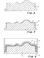
Figure 6 shows a sectional view of a master model structure, more particularly of a so-called ureol model; -
Figure 7 shows the ureol model illustrated inFigure 6 having applied thereon the textured elastic sheet material to form the master model; -
Figure 8 illustrates the master model ofFigure 7 arranged together with a support shell in a mould to produce an intermediate silicone impression; -
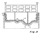
Figure 9 illustrates the silicone impression ofFigure 8 which is arranged, together with the support shell, in a reversed position in a further mould wherein a gel coat and a glass fibre-epoxy layer are moulded on top of the silicone impression to produce a so-called bath model; -
Figure 10 illustrates the bath model immersed in a nickel plating bath wherein a nickel shell is deposited by electric current onto the bath model, and -
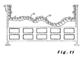
Figure 11 illustrates the nickel shell arranged on a supporting mould structure to produce the mould. - In the method according to the invention illustrated in the figures a desired texture is first of all cut in a
starting material 1. Thestarting material 1 is for example a silicone rubber sleeve or a "Novotek" sleeve which is applied onto aroll 2. By means of a mechanical milling device, but preferably by means of alaser 3 with laser beam 4, the desired texture is cut in thestarting material 1. The laser cutting technique is already known per se and disclosed for example inUS-A-5 759 473 so that it will not be described in great detail. Theroll 2 is for example rotated while the laser beam 4 is guided over the peripheral surface parallel to the axis of rotation in such a manner that essentially the entire peripheral surface is treated. During this movement of the laser beam 4 relative to the surface of theroll 2, the intensity of the laser beam 4 is controlled as a function of a control signal which may be obtained by scanning the surface of a patterned original or an artificially designed texture can be developed. In case of an existing texture, for example a leather, wood, stone or any other texture, the surface may be scanned optically or mechanically, and an electric signal is generated in accordance with the scanning results and may be used directly to control the position and intensity of the laser. A preferred alternative consists however in temporarily storing the electric signal obtained by scanning the patterned original. In this way the scanned texture can be processed to modify it. - In the prior art method, the laser cut roll is used to emboss a thermoplastic PVC film at a relatively high output by a continuous calendering process.
- In the method according to the present invention, at the most a few impressions have to be made of the starting
material 1, but these impressions have to be of a better quality. As illustrated inFigure 2 , the sleeve of startingmaterial 1 can be removed from theroll 2 and positioned in a flat state on a vacuum table 5. This vacuum table 5 has aflat bottom 6 provided with holes 7 ending in achamber 8 wherein a vacuum is created by means of a vacuum pump 9 so that the sheet of starting material is kept in a flat position. Referring toFigure 3 , aflowable impression material 10 is poured in a next step onto the startingmaterial 1 and is scraped off by means of ascraper 11. After having allowed theimpression material 10 to set, thesheet material 12 produced thereby is demoulded. This sheet material has for example an average thickness (calculated by dividing its volume by its surface area) of between 20 µm and 5 mm, and preferably between 0.5 mm and 2 mm, and is illustrated inFigure 4 . - As impression material for producing the
sheet material 12, use is made of a material which produces an elastic sheet material, showing in particular an elongation at break, measured according to ISO 527-3/2/100, of at least 20%, preferably of at least 50% and more preferably of at least 100%. Such an impression material may be a thermoplastic material such as PVC, TPO or TPU, a flowable silicone rubber or a reactive mixture such as a polyurethane reaction mixture composed of an isocyanate and a compound, in particular a polyalcohol or a polyamine, comprising groups which are reactive to the isocyanate compound. An essential feature of the impression material is that, at the temperature at which It is applied onto the starting material, it should have a Brookfield viscosity smaller than 100 Pa.s, in particular smaller than 50 Pa.s, so that it can copy the texture of the starting material sufficiently accurately. The thermoplastic materials should therefore be heated to a sufficiently high temperature and/or contain a sufficient amount of plasticizers in order to be suited for use as impression material. It should be noted that materials with the highest viscosities are in the form of a paste which requires some smearing action and/or some pressure in order to fill the surface relief of the starting material sufficiently completely. The term "flowable material" is therefore to be understood in the present specification as embracing not only materials which can be poured simply by gravity out of a container but also materials to which some pressure has to be applied in order to flow. The impression materials used in the method according to the invention for producing the elastic sheet material should however have such a Brookfield viscosity that they can be poured by gravity out of a container. In the method according to the invention, preference is given to materials which have even a lower viscosity at application temperature, more particularly a Brookfield viscosity smaller than 30 Pa.s, preferably smaller than 20 Pa.s and more preferably smaller than 10 Pa.s. Silicone rubbers, having a viscosity of for example 20 to 25 Pa.s, but especially polyurethane reaction mixtures, having an initial viscosity which is smaller than 10 Pa.s, or even smaller than 5 Pa.s, are preferred. - Examples of suitable polyurethane reaction mixtures can be found in
EP-B-0 379 246 , especially in Examples 1 to 18 thereof. For the present invention, some modifications can be applied to these examples. In view of the fact that for the present invention the curing time is of minor importance, the catalysts could for example be omitted or reduced and less reactive compounds could be used, for example a longer polyol and/or a polyol having a lower functionality, for example a minimum functionality of two, so as to achieve an even more elastic polyurethane. Instead of an aliphatic isocyanate, it is on the other hand possible to use a more reactive aromatic isocyanate. - The advantage of the use of a low viscous impression material, in particular a low viscous reaction mixture, is illustrated in
Figure 5 . This Figure illustrates the profile of the desired texture cut in the startingmaterial 1 and the profile of the resulting texture on the elastic sheet material moulded on top of the starting material. With a low viscous material less than 5% more particularly only 1 to 3 % of the quality, especially of the maximum peak to valley heights Rz, will be lost by making the impression due to the fact that the small recesses of the fine texture will usually not be filled completely. With the existing mechanical embossing process on the contrary, even the larger recesses of the coarse texture will not be completely filled resulting in a considerable loss of quality. In the example illustrated inFigure 5 , the fine texture superimposed onto the basic coarser texture is for example completely lost. - In the method according to the invention, a more uniform elastic sheet material can be made on the basis of the laser cut starting material than in the existing calendering process. In case a repeating pattern is provided on the
elastic sheet material 12, the maximum peak to valley heights Rz (measured as an average in accordance with ISO 4287-1997 andISO 11 562 over a sampling length λc determined in accordance with ISO 4288-1996) measured in the same location (where the elastic sheet material shows the same surface profile) in the different areas with repeating pattern vary for example within a range of less than 15%, in particular even less than 10%, above and below the average of the measured peak to valley heights in the different areas. When using such high quality textured sheet materials for making mould for adjoining trim parts, for example for a dash board and for a glove compartment cover or for an air bag, there will be no noticeable contrast between the texture qualities of these parts. - For making the
elastic sheet material 12 theflowable impression material 10 can be poured onto the startingmaterial 1 as described hereabove. Instead of pouring theimpression material 10, it could also be sprayed, for example by applying the technique disclosed for a polyurethane reaction mixture inEP-B-0 303 305 . The impression material could even be sprayed directly onto theroll 2, i.e. without removing the starting material therefrom, so that no vacuum table would be required. The impression material can also be smeared onto the textured surface. Moreover, it is possible to exert a pressure onto the impression material so that it penetrates even better in the smallest recesses of the textured surface, for example by injecting the flowable material under pressure in a closed mould cavity. Of course, the applied pressure should not be too large to avoid deformations of the textured surface. In practice, a RIM (reaction injection moulding) process should for example be suitable, in particular a polyurethane RIM process. - In the method illustrated in the figures, the
elastic sheet material 12 is made as a direct impression of the startingmaterial 1. In a variant embodiment, one or more intermediate impressions could be made by means of impression materials showing the same properties as described hereabove so that the quality of the texture is very little affected by making the different intermediate impressions. Instead of using a startingmaterial 1 wherein the desired texture is cut, it is also possible to start from an existing, in particular natural textured material, such a for example natural leather, a wooden panel, a piece of stone, a solidified sand surface, a metal piece, etc. This textured material can be applied onto the vacuum table or onto another moulding device so that theelastic sheet material 12 can be moulded directly onto this textured material. - In the method illustrated in the figures, the
elastic sheet material 12 is used to cover or wrap at least portions of amaster model structure 13 in order to achieve amaster model 14. If necessary two or moreelastic sheets 12 can be made by successive mouldings starting from a same starting material. Themaster model 14 shows a surface having a size and a shape corresponding to the size and the shape of the surface of the mould to be produced. By a corresponding size and shape is meant in the present specification a size and a shape which are substantially identical to the size and the shape of the mould surface or a size and a shape which are substantially identical to the size and the shape of a negative impression of the mould surface. Consequently, when making the further impressions to achieve the mould surface, no deformations will occur. - When applying the
elastic sheet material 12 onto themaster model structure 14, it has to be stretched to conform to the shape of this structure, which is possible due to the elastic nature of theelastic sheet material 12. - In a next step, illustrated in
Figure 8 , an intermediate impression is made, more particularly asilicon model 15. Themaster model 14 is placed in this step in amould 16 and asupport shell 17 is positioned on top of themaster model 14 so that a mould cavity is formed. This mould is filled with a silicone composition to produce thesilicon model 15. As illustrated inFigure 9 , thissilicon model 15 is used to produce, as a further intermediate impression, abath model 18. For making thisbath model 18, thesilicon model 15 is positioned together with thesupport shell 17 in afurther mould 19 and agel coat layer 20 and a glass fibre reinforcedepoxy layer 21 are moulded on top of thesilicon model 15. - As illustrated in
Figure 10 , the thus producedbath model 18 is subsequently immersed in anelectrolytic bath 22, more particularly in a nickel plating bath or galvanic cell. Thisbath 22 is filled with an electrolyte solution and twoanodes 23 are arranged in the bath. By applying a voltage between thebath model 18 and theanodes 23 an electric current flows in the bath and ametal layer 24, in particular a nickel shell, is gradually deposited onto thebath model 18. Thisnickel shell 24, showing an imprint of the original desired texture, forms a liner structure which is arranged in a last step onto a supporting mould structure 25 to produce amould 26, the mould surface of which is formed by theliner structure 24. Instead of using a nickel plating bath, it is also possible to deposit the metal layer onto the bath model by means of a metal vapour deposition process, more particularly by a nickel vapour deposition process. Since such vapour deposition processes are known per se, they will not be described in further detail in the present specification. - In the above described process, the different impressions can be made starting from the
master model 14 with such an accuracy that when the master model is provided with a texture showing a repeating pattern, the maximum peak to valley heights Rz (measured as an average in accordance with ISO 4287-1997 andISO 11 562 over a sampling length λc determined in accordance with ISO 4288-1996) measured in the same location in the different areas with repeating pattern vary within a range of less than 15%, preferably less than 10%, above and below the average of the measured peak to valley heights in the different areas. When the master model is made starting from an elastic sheet which is stretched in certain areas, the maximum peak to valley heights Rz have of course to be determined in areas of the mould surface where the elastic sheet was not, or substantially not stretched, since the stretching of the elastic sheet will have an effect on this value. The materials used for making the different intermediate impressions will normally have a viscosity in the same range as the viscosities described hereabove for the impression materials for making theelastic sheet material 12, unless a higher pressure can be used to mould these intermediate impressions. Also the electrolytic or vapour deposition processes produce only a negligible loss of texture quality. - Instead of a metal liner structure, it is also possible to make the liner structure from an elastic material. Such an elastic liner is preferably preshaped so that it has a shape and a size corresponding substantially to the shape and the size of the mould surface of the mould obtained when arranging the liner structure onto the mould structure. The liner structure may consist in particular of a rubber membrane, more particularly of a silicone rubber membrane, moulded in accordance with the shape of the mould surface.
- The moulds made in accordance with the methods described hereabove are used to produce an elastomeric skin by a method wherein a flowable skin material is applied onto the mould surface so that a predetermined texture is formed on the front side of the skin. Examples of such methods are spray processes, RIM processes and powder or liquid slush moulding processes. In the method according to the invention preference is given to a spray or a RIM process wherein a liquid polyurethane reaction mixture is applied onto the mould surface. Compared to slush moulding processes wherein the thermoplastic moulding material has to be heated to a temperature which is generally higher than 200°C and wherein the molten material has subsequently to be cooled down rather quickly, a spray or RIM mould is usually heated to a much lower temperature and does not need to be cooled down so that it is less subjected to thermal stresses. In practice, the mould surface of such moulds can therefore be made of materials which can be given a more accurate or a finer texture.
Claims (7)
- A method for making a mould (26) for producing at least an elastomeric skin in particular by a spray, RIM or slush moulding process, which skin shows a front surface having a predetermined texture being an impression of a desired texture, which method comprises the steps of :- providing a mould structure (25); and- arranging a liner structure (24) on the mould structure (25) to provide a mould surface having a size and a shape corresponding to the size and the shape of the front surface of the elastomeric skin and showing a texture which is a negative of said predetermined texture, the liner structure (24) being provided with said negative texture by applying an elastic sheet material (12) onto a master model structure (13) to provide a master model (14) showing a surface formed by the elastic sheet material (12) and having a size and a shape corresponding to the size and the shape of said mould surface, the elastic sheet material (12) being stretched when applying it onto the master model structure (13), and by making the liner structure (24) as a direct impression of the master model (14) or as an impression of one or more intermediate impressions (15, 18) of the master model (14), said direct impression or respectively said impression and said intermediate impressions being made by gradually depositing impression material on the master model (14) or on any intermediate impression (15, 18) or by a moulding process wherein a flowable impression material is applied onto the master model (14) or onto one of said intermediate impressions (15, 18) and wherein the flowable impression material is allowed to set to produce the impression; andwherein the elastic sheet material (12) is made as a direct impression of a starting material (1) or as an impression of one or more intermediate impressions of a starting material (1), which starting material (1) shows the desired texture or the desired texture being cut in the starting material (1), said direct impression or respectively said impression and said intermediate impressions being made by a further moulding process wherein a flowable impression material (10) having a Brookfield viscosity at application temperature smaller than 100 Pa.s, preferably smaller than 50 Pa.s, is applied in a layer onto the starting material (1) or on one of said intermediate impressions and wherein the impression material (10) is allowed to set to produce the impression, upon being applied onto the starting material (1) or onto one of said intermediate impressions the flowable impression material (10) or materials used in said further moulding process having such a Brookfield viscosity at the application temperature that they can be poured by gravity out of a container.
- A method according to claim 1, characterised in that the desired texture is cut by means of a laser beam (4) in the starting material.
- A method according to claim 1 or 2, characterised in that said elastic sheet (12) is made by moulding said impression material (10) by spraying, pouring, injecting or smearing it in a layer onto the starting material (1), the impression material (10) being preferably flowable molten PVC, flowable silicone rubber or a liquid polyurethane reaction mixture, preference being more particularly given to the use of a liquid polyurethane reaction mixture.
- A method according to any one of the claims 1 to 3, characterised in that the liner structure (24) is made of a metal or metal alloy which is gradually deposited on the master model (14) or on one of said intermediate impressions (15, 18), in particular by metal plating in an electrolytic cell or by a metal vapour deposition process, the metal being preferably nickel.
- A method according to any one of the claims 1 to 4, characterised in that said elastic sheet (12) shows an elongation at break, measured according to ISO 527-3/2/100, of at least 20%, preferably at least 50% and more preferably at least 100%.
- A method according to any one of the claims 1 to 5, characterised in that it comprises the further step of using the mould (26) to produce elastomeric skins by a spray, RIM or slush moulding process against said mould surface.
- A method according to claim 6, characterised in that the elastomeric skins are produced by applying a polyurethane reaction mixture either by a spray or a RIM process against the mould surface and by allowing the reaction mixture to cure, an in-mould coating, in particular an in-mould paint being optionally first applied against the mould surface.
Priority Applications (1)
| Application Number | Priority Date | Filing Date | Title |
|---|---|---|---|
| EP03714561A EP1490201B1 (en) | 2002-03-25 | 2003-03-25 | Method for making a mould for producing an elastomeric skin |
Applications Claiming Priority (4)
| Application Number | Priority Date | Filing Date | Title |
|---|---|---|---|
| EP02447044A EP1348529A1 (en) | 2002-03-25 | 2002-03-25 | Method for making a mould and for producing an elastomeric skin |
| EP02447044 | 2002-03-25 | ||
| EP03714561A EP1490201B1 (en) | 2002-03-25 | 2003-03-25 | Method for making a mould for producing an elastomeric skin |
| PCT/BE2003/000053 WO2003080309A1 (en) | 2002-03-25 | 2003-03-25 | Method for making a mould and for producing an elastomeric skin |
Publications (2)
| Publication Number | Publication Date |
|---|---|
| EP1490201A1 EP1490201A1 (en) | 2004-12-29 |
| EP1490201B1 true EP1490201B1 (en) | 2008-07-30 |
Family
ID=27798977
Family Applications (2)
| Application Number | Title | Priority Date | Filing Date |
|---|---|---|---|
| EP02447044A Withdrawn EP1348529A1 (en) | 2002-03-25 | 2002-03-25 | Method for making a mould and for producing an elastomeric skin |
| EP03714561A Expired - Lifetime EP1490201B1 (en) | 2002-03-25 | 2003-03-25 | Method for making a mould for producing an elastomeric skin |
Family Applications Before (1)
| Application Number | Title | Priority Date | Filing Date |
|---|---|---|---|
| EP02447044A Withdrawn EP1348529A1 (en) | 2002-03-25 | 2002-03-25 | Method for making a mould and for producing an elastomeric skin |
Country Status (16)
| Country | Link |
|---|---|
| US (1) | US20050218555A1 (en) |
| EP (2) | EP1348529A1 (en) |
| JP (1) | JP2005520713A (en) |
| CN (1) | CN1642705A (en) |
| AT (1) | ATE402799T1 (en) |
| AU (1) | AU2003218920A1 (en) |
| BR (1) | BR0308628A (en) |
| CA (1) | CA2478847A1 (en) |
| DE (1) | DE60322521D1 (en) |
| HR (1) | HRP20040997A2 (en) |
| MX (1) | MXPA04009323A (en) |
| PL (1) | PL371104A1 (en) |
| RS (1) | RS85204A (en) |
| RU (1) | RU2004130871A (en) |
| WO (1) | WO2003080309A1 (en) |
| ZA (1) | ZA200408276B (en) |
Families Citing this family (13)
| Publication number | Priority date | Publication date | Assignee | Title |
|---|---|---|---|---|
| JP4953420B2 (en) * | 2005-12-28 | 2012-06-13 | 日本プラスト株式会社 | Molded product and insert molding method |
| WO2007100922A2 (en) | 2006-02-28 | 2007-09-07 | Polyworks, Inc. | Methods of making polymeric articles and polymeric articles formed thereby |
| GB2447021B (en) * | 2007-02-27 | 2010-03-17 | Rolls Royce Plc | A mould lining |
| BRPI0809582A2 (en) * | 2007-04-12 | 2014-09-23 | Abb Technology Ag | EXTERNAL ELECTRICAL DEVICE WITH A RESIN INSULATION SYSTEM |
| US8871328B2 (en) | 2007-04-13 | 2014-10-28 | Daniel M. Wyner | Impact and vibration absorbing body-contacting medallions, methods of using and methods of making |
| CN100478120C (en) * | 2007-08-30 | 2009-04-15 | 广东星联精密机械有限公司 | Method for ensuring the axiality of the injection molding cooling deep borehole and the external-molding surface |
| CN102046365A (en) | 2008-04-14 | 2011-05-04 | 宝立沃克斯公司 | Deep drawing method for making shock and vibration absorbing articles and articles formed therefrom |
| US20100102478A1 (en) * | 2008-10-23 | 2010-04-29 | Flavio Maschera | Method of fabricating bath-models for nickel shells |
| IT1395673B1 (en) * | 2009-08-25 | 2012-10-16 | Cielle S R L | MATRIX FOR THE MANUFACTURE OF MOLDS FOR THE PRODUCTION OF TILES AND TO ITS MANUFACTURING PROCEDURE |
| US20120121871A1 (en) * | 2010-11-17 | 2012-05-17 | Ming-Hung Huang | In-mold roller manufacturing method and casing product made thereby |
| CN108025494B (en) * | 2015-11-26 | 2020-03-10 | 瓦克化学股份公司 | High-viscosity silicone composition for producing elastomeric molded parts by ballistic generating method |
| DE102016207605A1 (en) * | 2016-05-03 | 2017-11-09 | Volkswagen Aktiengesellschaft | Method and device for injection molding a curved glass body |
| JP7662461B2 (en) | 2021-09-13 | 2025-04-15 | トヨタ自動車株式会社 | Tank entry model |
Family Cites Families (7)
| Publication number | Priority date | Publication date | Assignee | Title |
|---|---|---|---|---|
| JPH0641149B2 (en) * | 1986-07-21 | 1994-06-01 | 三ツ星ベルト株式会社 | Epidermis manufacturing method |
| DE3913157A1 (en) * | 1988-05-14 | 1990-01-04 | Guenther Troester Fa | METHOD FOR THE PRODUCTION OF ELASTOMER SKINS AS A CLADDING MATERIAL FOR PLASTIC MOLDED BODIES, e.g. MOTOR VEHICLE FITTING PANELS |
| US5538674A (en) * | 1993-11-19 | 1996-07-23 | Donnelly Corporation | Method for reproducing holograms, kinoforms, diffractive optical elements and microstructures |
| US5492663A (en) * | 1994-06-20 | 1996-02-20 | General Motors Corporation | Coordinated texture harmony between formed material and molded components |
| DE4441216C2 (en) * | 1994-11-19 | 2000-10-26 | Benecke Kaliko Ag | Process for producing an embossing roller for continuously embossing the surface of a thermoplastic film |
| US6558496B1 (en) * | 1997-11-28 | 2003-05-06 | Eschmann-Stahl Gmbh & Co., Kg | Rapid texture prototyping |
| GB9907273D0 (en) * | 1999-03-31 | 1999-05-26 | Gravutex Eschmann Internationa | Rapid texture prototyping |
-
2002
- 2002-03-25 EP EP02447044A patent/EP1348529A1/en not_active Withdrawn
-
2003
- 2003-03-25 EP EP03714561A patent/EP1490201B1/en not_active Expired - Lifetime
- 2003-03-25 RS YUP-852/04A patent/RS85204A/en unknown
- 2003-03-25 AU AU2003218920A patent/AU2003218920A1/en not_active Abandoned
- 2003-03-25 CA CA002478847A patent/CA2478847A1/en not_active Abandoned
- 2003-03-25 US US10/507,745 patent/US20050218555A1/en not_active Abandoned
- 2003-03-25 WO PCT/BE2003/000053 patent/WO2003080309A1/en not_active Ceased
- 2003-03-25 DE DE60322521T patent/DE60322521D1/en not_active Expired - Lifetime
- 2003-03-25 PL PL03371104A patent/PL371104A1/en unknown
- 2003-03-25 MX MXPA04009323A patent/MXPA04009323A/en unknown
- 2003-03-25 CN CN03806976.8A patent/CN1642705A/en active Pending
- 2003-03-25 JP JP2003578118A patent/JP2005520713A/en active Pending
- 2003-03-25 RU RU2004130871/12A patent/RU2004130871A/en not_active Application Discontinuation
- 2003-03-25 BR BR0308628-3A patent/BR0308628A/en not_active IP Right Cessation
- 2003-03-25 AT AT03714561T patent/ATE402799T1/en not_active IP Right Cessation
- 2003-03-25 HR HRP20040997 patent/HRP20040997A2/en not_active Application Discontinuation
-
2004
- 2004-10-13 ZA ZA200408276A patent/ZA200408276B/en unknown
Also Published As
| Publication number | Publication date |
|---|---|
| BR0308628A (en) | 2005-02-15 |
| EP1490201A1 (en) | 2004-12-29 |
| PL371104A1 (en) | 2005-06-13 |
| ATE402799T1 (en) | 2008-08-15 |
| RU2004130871A (en) | 2005-05-20 |
| ZA200408276B (en) | 2006-07-26 |
| HRP20040997A2 (en) | 2004-12-31 |
| CN1642705A (en) | 2005-07-20 |
| CA2478847A1 (en) | 2003-10-02 |
| DE60322521D1 (en) | 2008-09-11 |
| JP2005520713A (en) | 2005-07-14 |
| AU2003218920A1 (en) | 2003-10-08 |
| WO2003080309A1 (en) | 2003-10-02 |
| EP1348529A1 (en) | 2003-10-01 |
| RS85204A (en) | 2007-02-05 |
| US20050218555A1 (en) | 2005-10-06 |
| MXPA04009323A (en) | 2005-01-25 |
Similar Documents
| Publication | Publication Date | Title |
|---|---|---|
| EP1348529A1 (en) | Method for making a mould and for producing an elastomeric skin | |
| EP1355776B1 (en) | Process and mould for the production of a layer shaped part, in particular a reaction injection moulding process for the production of a polyurethane skin layer | |
| EP1126958B1 (en) | Method for manufacturing a multi-layered moulded synthetic part and thus obtained part | |
| US5013508A (en) | Method for producing elastomer skins as lining material for plastic molded articles such as automobile dashboards | |
| RU2340452C2 (en) | Method of production of composite part of automotive vehicle interior finish | |
| CA2182971C (en) | Nickel shell door molds | |
| MXPA03010496A (en) | Method for the manufacture of a molded body firmly bonded to a grained or structured molded skin and a device for performing the method. | |
| HUT71501A (en) | Method for manufacturing self-supporting synthetic trim parts and thus manufactured trim parts | |
| JPS63500365A (en) | Method of manufacturing molded layer by spray gun painting | |
| BG63040B1 (en) | Method for forming of components having controllable width layers | |
| EP2448738B1 (en) | Method of making an elastomeric skin | |
| EP1169166B1 (en) | Rapid texture prototyping | |
| KR20050020766A (en) | Method for making a mould and for producing an elastomeric skin | |
| CN213471924U (en) | Mold for manufacturing formed shell of vehicle interior lining | |
| US20030201561A1 (en) | Heating and particulate drawing process and assembly for aggregating plasticized granules in adhering fashion to an exposed face of a heated tool or part | |
| GB2401574A (en) | Making a skin of an interior trim part | |
| HK1039298B (en) | Method for manufacturing a multi-layered moulded synthetic part and thus obtained part | |
| JPH0633290A (en) | Matrix for electroforming and its production |
Legal Events
| Date | Code | Title | Description |
|---|---|---|---|
| PUAI | Public reference made under article 153(3) epc to a published international application that has entered the european phase |
Free format text: ORIGINAL CODE: 0009012 |
|
| 17P | Request for examination filed |
Effective date: 20041021 |
|
| AK | Designated contracting states |
Kind code of ref document: A1 Designated state(s): AT BE BG CH CY CZ DE DK EE ES FI FR GB GR HU IE IT LI LU MC NL PT RO SE SI SK TR |
|
| AX | Request for extension of the european patent |
Extension state: AL LT LV MK |
|
| 17Q | First examination report despatched |
Effective date: 20050114 |
|
| RAP1 | Party data changed (applicant data changed or rights of an application transferred) |
Owner name: RECTICEL |
|
| GRAP | Despatch of communication of intention to grant a patent |
Free format text: ORIGINAL CODE: EPIDOSNIGR1 |
|
| RTI1 | Title (correction) |
Free format text: METHOD FOR MAKING A MOULD FOR PRODUCING AN ELASTOMERIC SKIN |
|
| GRAS | Grant fee paid |
Free format text: ORIGINAL CODE: EPIDOSNIGR3 |
|
| GRAA | (expected) grant |
Free format text: ORIGINAL CODE: 0009210 |
|
| AK | Designated contracting states |
Kind code of ref document: B1 Designated state(s): AT BE BG CH CY CZ DE DK EE ES FI FR GB GR HU IE IT LI LU MC NL PT RO SE SI SK TR |
|
| REG | Reference to a national code |
Ref country code: GB Ref legal event code: FG4D |
|
| REG | Reference to a national code |
Ref country code: CH Ref legal event code: EP |
|
| RAP2 | Party data changed (patent owner data changed or rights of a patent transferred) |
Owner name: RECTICEL AUTOMOBILSYSTEME GMBH |
|
| REF | Corresponds to: |
Ref document number: 60322521 Country of ref document: DE Date of ref document: 20080911 Kind code of ref document: P |
|
| REG | Reference to a national code |
Ref country code: IE Ref legal event code: FG4D |
|
| NLT2 | Nl: modifications (of names), taken from the european patent patent bulletin |
Owner name: RECTICEL AUTOMOBILSYSTEME GMBH Effective date: 20080910 |
|
| PG25 | Lapsed in a contracting state [announced via postgrant information from national office to epo] |
Ref country code: ES Free format text: LAPSE BECAUSE OF FAILURE TO SUBMIT A TRANSLATION OF THE DESCRIPTION OR TO PAY THE FEE WITHIN THE PRESCRIBED TIME-LIMIT Effective date: 20081110 Ref country code: NL Free format text: LAPSE BECAUSE OF FAILURE TO SUBMIT A TRANSLATION OF THE DESCRIPTION OR TO PAY THE FEE WITHIN THE PRESCRIBED TIME-LIMIT Effective date: 20080730 Ref country code: PT Free format text: LAPSE BECAUSE OF FAILURE TO SUBMIT A TRANSLATION OF THE DESCRIPTION OR TO PAY THE FEE WITHIN THE PRESCRIBED TIME-LIMIT Effective date: 20081230 |
|
| PG25 | Lapsed in a contracting state [announced via postgrant information from national office to epo] |
Ref country code: FI Free format text: LAPSE BECAUSE OF FAILURE TO SUBMIT A TRANSLATION OF THE DESCRIPTION OR TO PAY THE FEE WITHIN THE PRESCRIBED TIME-LIMIT Effective date: 20080730 Ref country code: BG Free format text: LAPSE BECAUSE OF FAILURE TO SUBMIT A TRANSLATION OF THE DESCRIPTION OR TO PAY THE FEE WITHIN THE PRESCRIBED TIME-LIMIT Effective date: 20081030 Ref country code: SI Free format text: LAPSE BECAUSE OF FAILURE TO SUBMIT A TRANSLATION OF THE DESCRIPTION OR TO PAY THE FEE WITHIN THE PRESCRIBED TIME-LIMIT Effective date: 20080730 Ref country code: AT Free format text: LAPSE BECAUSE OF FAILURE TO SUBMIT A TRANSLATION OF THE DESCRIPTION OR TO PAY THE FEE WITHIN THE PRESCRIBED TIME-LIMIT Effective date: 20080730 |
|
| PG25 | Lapsed in a contracting state [announced via postgrant information from national office to epo] |
Ref country code: DK Free format text: LAPSE BECAUSE OF FAILURE TO SUBMIT A TRANSLATION OF THE DESCRIPTION OR TO PAY THE FEE WITHIN THE PRESCRIBED TIME-LIMIT Effective date: 20080730 Ref country code: EE Free format text: LAPSE BECAUSE OF FAILURE TO SUBMIT A TRANSLATION OF THE DESCRIPTION OR TO PAY THE FEE WITHIN THE PRESCRIBED TIME-LIMIT Effective date: 20080730 |
|
| PG25 | Lapsed in a contracting state [announced via postgrant information from national office to epo] |
Ref country code: SK Free format text: LAPSE BECAUSE OF FAILURE TO SUBMIT A TRANSLATION OF THE DESCRIPTION OR TO PAY THE FEE WITHIN THE PRESCRIBED TIME-LIMIT Effective date: 20080730 Ref country code: RO Free format text: LAPSE BECAUSE OF FAILURE TO SUBMIT A TRANSLATION OF THE DESCRIPTION OR TO PAY THE FEE WITHIN THE PRESCRIBED TIME-LIMIT Effective date: 20080730 Ref country code: CZ Free format text: LAPSE BECAUSE OF FAILURE TO SUBMIT A TRANSLATION OF THE DESCRIPTION OR TO PAY THE FEE WITHIN THE PRESCRIBED TIME-LIMIT Effective date: 20080730 |
|
| PLBE | No opposition filed within time limit |
Free format text: ORIGINAL CODE: 0009261 |
|
| STAA | Information on the status of an ep patent application or granted ep patent |
Free format text: STATUS: NO OPPOSITION FILED WITHIN TIME LIMIT |
|
| 26N | No opposition filed |
Effective date: 20090506 |
|
| PG25 | Lapsed in a contracting state [announced via postgrant information from national office to epo] |
Ref country code: IT Free format text: LAPSE BECAUSE OF FAILURE TO SUBMIT A TRANSLATION OF THE DESCRIPTION OR TO PAY THE FEE WITHIN THE PRESCRIBED TIME-LIMIT Effective date: 20080730 |
|
| PG25 | Lapsed in a contracting state [announced via postgrant information from national office to epo] |
Ref country code: MC Free format text: LAPSE BECAUSE OF NON-PAYMENT OF DUE FEES Effective date: 20090331 |
|
| REG | Reference to a national code |
Ref country code: CH Ref legal event code: PL |
|
| GBPC | Gb: european patent ceased through non-payment of renewal fee |
Effective date: 20090325 |
|
| REG | Reference to a national code |
Ref country code: FR Ref legal event code: ST Effective date: 20091130 |
|
| PG25 | Lapsed in a contracting state [announced via postgrant information from national office to epo] |
Ref country code: SE Free format text: LAPSE BECAUSE OF FAILURE TO SUBMIT A TRANSLATION OF THE DESCRIPTION OR TO PAY THE FEE WITHIN THE PRESCRIBED TIME-LIMIT Effective date: 20081030 Ref country code: LI Free format text: LAPSE BECAUSE OF NON-PAYMENT OF DUE FEES Effective date: 20090331 Ref country code: IE Free format text: LAPSE BECAUSE OF NON-PAYMENT OF DUE FEES Effective date: 20090325 Ref country code: CH Free format text: LAPSE BECAUSE OF NON-PAYMENT OF DUE FEES Effective date: 20090331 |
|
| PG25 | Lapsed in a contracting state [announced via postgrant information from national office to epo] |
Ref country code: FR Free format text: LAPSE BECAUSE OF NON-PAYMENT OF DUE FEES Effective date: 20091123 Ref country code: GB Free format text: LAPSE BECAUSE OF NON-PAYMENT OF DUE FEES Effective date: 20090325 |
|
| PG25 | Lapsed in a contracting state [announced via postgrant information from national office to epo] |
Ref country code: GR Free format text: LAPSE BECAUSE OF FAILURE TO SUBMIT A TRANSLATION OF THE DESCRIPTION OR TO PAY THE FEE WITHIN THE PRESCRIBED TIME-LIMIT Effective date: 20081031 |
|
| PG25 | Lapsed in a contracting state [announced via postgrant information from national office to epo] |
Ref country code: LU Free format text: LAPSE BECAUSE OF NON-PAYMENT OF DUE FEES Effective date: 20090325 |
|
| PG25 | Lapsed in a contracting state [announced via postgrant information from national office to epo] |
Ref country code: HU Free format text: LAPSE BECAUSE OF FAILURE TO SUBMIT A TRANSLATION OF THE DESCRIPTION OR TO PAY THE FEE WITHIN THE PRESCRIBED TIME-LIMIT Effective date: 20090131 |
|
| PG25 | Lapsed in a contracting state [announced via postgrant information from national office to epo] |
Ref country code: TR Free format text: LAPSE BECAUSE OF FAILURE TO SUBMIT A TRANSLATION OF THE DESCRIPTION OR TO PAY THE FEE WITHIN THE PRESCRIBED TIME-LIMIT Effective date: 20080730 |
|
| PG25 | Lapsed in a contracting state [announced via postgrant information from national office to epo] |
Ref country code: CY Free format text: LAPSE BECAUSE OF FAILURE TO SUBMIT A TRANSLATION OF THE DESCRIPTION OR TO PAY THE FEE WITHIN THE PRESCRIBED TIME-LIMIT Effective date: 20080730 |
|
| PGFP | Annual fee paid to national office [announced via postgrant information from national office to epo] |
Ref country code: DE Payment date: 20200320 Year of fee payment: 18 |
|
| PGFP | Annual fee paid to national office [announced via postgrant information from national office to epo] |
Ref country code: BE Payment date: 20200319 Year of fee payment: 18 |
|
| REG | Reference to a national code |
Ref country code: DE Ref legal event code: R119 Ref document number: 60322521 Country of ref document: DE |
|
| REG | Reference to a national code |
Ref country code: BE Ref legal event code: MM Effective date: 20210331 |
|
| PG25 | Lapsed in a contracting state [announced via postgrant information from national office to epo] |
Ref country code: DE Free format text: LAPSE BECAUSE OF NON-PAYMENT OF DUE FEES Effective date: 20211001 |
|
| PG25 | Lapsed in a contracting state [announced via postgrant information from national office to epo] |
Ref country code: BE Free format text: LAPSE BECAUSE OF NON-PAYMENT OF DUE FEES Effective date: 20210331 |