EP1490176B1 - Bottle with evaporation limitation - Google Patents
Bottle with evaporation limitation Download PDFInfo
- Publication number
- EP1490176B1 EP1490176B1 EP03746073A EP03746073A EP1490176B1 EP 1490176 B1 EP1490176 B1 EP 1490176B1 EP 03746073 A EP03746073 A EP 03746073A EP 03746073 A EP03746073 A EP 03746073A EP 1490176 B1 EP1490176 B1 EP 1490176B1
- Authority
- EP
- European Patent Office
- Prior art keywords
- bottle
- fluid
- evaporation
- straw
- diameter
- Prior art date
- Legal status (The legal status is an assumption and is not a legal conclusion. Google has not performed a legal analysis and makes no representation as to the accuracy of the status listed.)
- Expired - Lifetime
Links
- 230000008020 evaporation Effects 0.000 title abstract description 69
- 238000001704 evaporation Methods 0.000 title abstract description 69
- 239000012530 fluid Substances 0.000 claims abstract description 98
- 238000009792 diffusion process Methods 0.000 claims abstract description 11
- 239000010902 straw Substances 0.000 abstract description 46
- 239000003153 chemical reaction reagent Substances 0.000 description 32
- 238000012360 testing method Methods 0.000 description 13
- 230000000694 effects Effects 0.000 description 11
- 238000013461 design Methods 0.000 description 8
- 238000000034 method Methods 0.000 description 8
- 238000002835 absorbance Methods 0.000 description 5
- 238000010276 construction Methods 0.000 description 5
- 239000011888 foil Substances 0.000 description 5
- 230000009467 reduction Effects 0.000 description 5
- 238000005259 measurement Methods 0.000 description 3
- 238000003556 assay Methods 0.000 description 2
- 230000007613 environmental effect Effects 0.000 description 2
- 238000003018 immunoassay Methods 0.000 description 2
- 239000007788 liquid Substances 0.000 description 2
- 239000000463 material Substances 0.000 description 2
- 210000003739 neck Anatomy 0.000 description 2
- XLYOFNOQVPJJNP-UHFFFAOYSA-N water Substances O XLYOFNOQVPJJNP-UHFFFAOYSA-N 0.000 description 2
- 241001474791 Proboscis Species 0.000 description 1
- 238000011481 absorbance measurement Methods 0.000 description 1
- 230000000052 comparative effect Effects 0.000 description 1
- 238000003780 insertion Methods 0.000 description 1
- 230000037431 insertion Effects 0.000 description 1
- 230000007774 longterm Effects 0.000 description 1
- 239000002184 metal Substances 0.000 description 1
- 230000035945 sensitivity Effects 0.000 description 1
- 239000003447 supported reagent Substances 0.000 description 1
- 239000002699 waste material Substances 0.000 description 1
- 238000007704 wet chemistry method Methods 0.000 description 1
Images


Classifications
-
- B—PERFORMING OPERATIONS; TRANSPORTING
- B01—PHYSICAL OR CHEMICAL PROCESSES OR APPARATUS IN GENERAL
- B01L—CHEMICAL OR PHYSICAL LABORATORY APPARATUS FOR GENERAL USE
- B01L3/00—Containers or dishes for laboratory use, e.g. laboratory glassware; Droppers
- B01L3/08—Flasks
-
- B—PERFORMING OPERATIONS; TRANSPORTING
- B01—PHYSICAL OR CHEMICAL PROCESSES OR APPARATUS IN GENERAL
- B01L—CHEMICAL OR PHYSICAL LABORATORY APPARATUS FOR GENERAL USE
- B01L2200/00—Solutions for specific problems relating to chemical or physical laboratory apparatus
- B01L2200/02—Adapting objects or devices to another
- B01L2200/026—Fluid interfacing between devices or objects, e.g. connectors, inlet details
-
- B—PERFORMING OPERATIONS; TRANSPORTING
- B01—PHYSICAL OR CHEMICAL PROCESSES OR APPARATUS IN GENERAL
- B01L—CHEMICAL OR PHYSICAL LABORATORY APPARATUS FOR GENERAL USE
- B01L2200/00—Solutions for specific problems relating to chemical or physical laboratory apparatus
- B01L2200/14—Process control and prevention of errors
- B01L2200/142—Preventing evaporation
-
- B—PERFORMING OPERATIONS; TRANSPORTING
- B01—PHYSICAL OR CHEMICAL PROCESSES OR APPARATUS IN GENERAL
- B01L—CHEMICAL OR PHYSICAL LABORATORY APPARATUS FOR GENERAL USE
- B01L2200/00—Solutions for specific problems relating to chemical or physical laboratory apparatus
- B01L2200/16—Reagents, handling or storing thereof
-
- G—PHYSICS
- G01—MEASURING; TESTING
- G01N—INVESTIGATING OR ANALYSING MATERIALS BY DETERMINING THEIR CHEMICAL OR PHYSICAL PROPERTIES
- G01N35/00—Automatic analysis not limited to methods or materials provided for in any single one of groups G01N1/00 - G01N33/00; Handling materials therefor
- G01N2035/00178—Special arrangements of analysers
- G01N2035/00277—Special precautions to avoid contamination (e.g. enclosures, glove- boxes, sealed sample carriers, disposal of contaminated material)
- G01N2035/00287—Special precautions to avoid contamination (e.g. enclosures, glove- boxes, sealed sample carriers, disposal of contaminated material) movable lid/cover for sample or reaction tubes
-
- Y—GENERAL TAGGING OF NEW TECHNOLOGICAL DEVELOPMENTS; GENERAL TAGGING OF CROSS-SECTIONAL TECHNOLOGIES SPANNING OVER SEVERAL SECTIONS OF THE IPC; TECHNICAL SUBJECTS COVERED BY FORMER USPC CROSS-REFERENCE ART COLLECTIONS [XRACs] AND DIGESTS
- Y10—TECHNICAL SUBJECTS COVERED BY FORMER USPC
- Y10T—TECHNICAL SUBJECTS COVERED BY FORMER US CLASSIFICATION
- Y10T436/00—Chemistry: analytical and immunological testing
- Y10T436/25—Chemistry: analytical and immunological testing including sample preparation
- Y10T436/2575—Volumetric liquid transfer
Definitions
- This invention relates generally to the field of clinical chemistry, and more particularly to a fluid supply apparatus for a clinical analyzer or similar apparatus having improved features for controlling evaporation.
- Clinical chemistry analyzers such as those manufactured by Abbott Laboratories and the Johnson and Johnson Company, among others, having reagent supplies on board for use in preparing wet immunoassays are sensitive to the effect of reagent evaporation, thereby causing prediction shifts with storage time:
- the change in the concentration of reagents that occurs with evaporation causes the reaction concentrations in a reaction vessel, such as a cuvette, to change, thereby causing the prediction shifts.
- Assay systems with a large reagent concentration sensitivity such as EMIT TDM assays, for example, need effective evaporation control to achieve acceptable onboard stability times. Stability goals require that reagents be stable for 2 or more weeks onboard a clinical analyzer.
- Most known "wet" analyzer systems use one of three methods to control such evaporation effects, as found with reagent supplies containing a plurality of bottles of at least one reagent.
- the first method is to package large volume reagent bottles on board and to use relatively large amounts of fluid in each test. This method does not reduce evaporation, but the effect is spread across a large fluid volume so that the effect on reagent concentration is minimized.
- This method of control requires a large reagent storage area within the analyzer and increases the cost per test as more fluid is used in each test.
- a second method of evaporation control is to cap the reagent bottles between each use. This method does reduce evaporation effects, but only while the bottles are capped, and further requires a cap opening mechanism which must be disposed within the analyzer to open and close the caps between uses. This mechanism and its associated control adds significantly to the overall cost and complexity of the analyzer. In addition, evaporation still occurs as each bottle opening operation tends to flush out air contained in the bottle and in fact, actually increases or promotes evaporation. A more expensive bottle design is also needed using this method, as the bottle caps that are used during long-term storage must be compatible with the bottle opening mechanism.
- a third known evaporation control method is to restrict the size of the metering access hole in the top of the reagent supply bottle.
- the bottles are stored uncapped within the reagent supply and using a small diameter hole reduces evaporation out of the reagent supply.
- This form of control works well with syringe metering systems that utilize relatively narrow metal tubes ( ⁇ 2 mm in diameter), but a metering system using disposable metering tips having larger diameters on the order of about 10 mm or more requires a reagent bottle(s) having a relatively large accommodating metering access hole or opening which does not control evaporation acceptably.
- the diameter of the necks of the larger diameter reagent bottles must also be large enough to accept a relatively large metering tip and associated mechanism which passes into the bottle interior in order to aspirate fluid therefrom.
- US-A-5102631 discloses an evaporation reduction apparatus for open mouth liquid containers, comprising an elongated tube having an upper end portion of such outside dimension in relationship to the inside container mouth dimension to form a press fit upon insertion of the tube into the container.
- the present invention provides a bottle for use in a clinical analyzer, said bottle having an interior sized for retaining a predetermined quantity of fluid and for receiving a fluid aspirating element for periodically removing a portion of said quantity of fluid, said bottle including an upper portion, an intermediate portion and a lower fluid retaining portion; characterised in that the diameter of the interior of the upper portion (124) tapers inwardly to a minimum inner diameter at the intermediate portion which is disposed immediately above the fluid retaining portion, and in that the inner diameter of the fluid retaining portion is substantially larger than the minimum inner diameter so as ; to produce a stagnant diffusion zone extending from immediately above said fluid retaining portion.
- FIG. 1 is a side elevational view, shown in section, of a fluid supply which is not within the scope of the present invention
- FIG. 2 is a side elevational view of an evaporation control element that is inserted into the fluid supply of Fig. 1;
- FIG. 3 is a rotated perspective view of the evaporation control element depicted in Figs. 1 and 2;
- FIG. 4 is an enlarged view of the top of the fluid supply of Fig. 1;
- FIG. 5 is an enlarged view of the bottom of the fluid supply of Fig. 1;
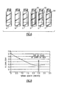
- FIG. 6 is a front view of a first plurality of fluid supply designs having varying evaporative control features
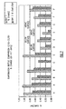
- FIG. 7 is a pictorial view of the amount of evaporation rate change over time relative to the fluid supplies depicted in Fig. 6;
- FIG. 8 is a graphical illustration of the effects of tube/diffusion length relative to evaporation control for the bottles depicted in Fig. 6;
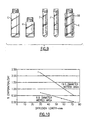
- FIG. 9 is a front view of a second plurality of fluid bottles used for comparative testing.
- FIG. 10 is a graphical illustration of the effects of tube/diffusion length and exposed fluid surface area relative to the fluid supplies of Fig. 9;
- FIG. 12 is a side perspective view of a fluid supply made in accordance with a preferred embodiment of the invention.
- FIG. 13 is a side view taken in section of the fluid supply of Fig. 12.
- Fig. 1 depicts a reagent pack 10 which does not form part of the present invention that is sized to be fitted into a rotatable wheel of a reagent supply (not shown) of a clinical analyzer.
- the reagent pack 10 is made from an moldable bio-compatible plastic material and comprises a support 14 that includes an integral bottle 20:
- the bottle 20 includes a top opening 24, shown in Fig. 4, extending into a hollow interior 28 for retaining a volume of fluid, such as a reagent used in preparing immunoassays.
- An evaporation control element 32 is sized to be fitted into the bottle interior 28.
- the bottle 20 has a total height of approximately 85 mm and an inside diameter of approximately 19.5 mm.
- the bottle 20 includes a cylindrical wall 36 that extends from a tapered bottom 40 to a top necked portion 44, Fig. 4, having exterior cap threads 48, Fig. 4.
- the reagent supply includes a cover that includes a metering opening which permits the passage of a fluid aspirating/dispensing member, such as a disposable metering tip 52.
- a "metering tip” refers to a fluid aspirating/dispensing member that can be attached to a proboscis as used in a metering mechanism (not shown) as described for example, in commonly owned U.S. Patent No. US 2003022380, filed June 28, 2002.
- the disposable metering tip 52 includes an open upper end and a lower dispense end and is capable of retaining a volumetric or micro-volumetric quantity of fluid.
- Metering tips in and of themselves are repletely well known in the field and do not form a specific part of the present invention.
- the metering tip 52 described herein is a disposable plastic member manufactured by Ortho Clinical Diagnostics, Inc. under the trade name of Vitros TM , though it will be apparent that other suitable fluid dispensing/aspirating members can be substituted.
- Temperature and humidity control systems are also provided within the reagent supply for maintaining a relatively constant environment for a plurality of supported reagent packs 10.
- the clinical analyzer rotates the wheel of the reagent supply until the top opening 24 is aligned with the metering opening and a metering mechanism raises and lowers the disposable metering tip into the confines of the bottle interior 28. A predetermined volume of fluid is then aspirated into the metering tip 52 and the tip is withdrawn by the metering mechanism.
- the evaporation control element hereinafter synonymously referred to as an evaporation straw, is inserted into the bottle interior 28.
- the evaporation straw 32 which includes a pair of open ends and is essentially hollow, is preferably made from a plastic molded material and includes an upper end 33 which when inserted into the bottle 20 creates an interference fit with the inside of the top necked portion 44 and is suspended into the bottle.
- the upper end 33 of the evaporation straw 32 includes an annular tab 76 that engages a circumferential slot 80 provided in the top necked portion 44 of the bottle 20.
- the inside diameter of the evaporation straw 32 has a narrowed tubular construction which tapers down, according to this arrangement, from a diameter of approximately 13 mm at the upper end 33 of the straw to a diameter of approximately 5 mm at an opposing bottom end 35.
- the overall length of the evaporation straw 32 used according to this arrangement is approximately 72 mm and therefore the bottom of the straw reaches to within approximately 1.5 mm of the bottom of the bottle interior 28.
- the evaporation straw 32 can also touch the bottom of the bottle if need be, as aligned cutouts 68 allow fluid movement around the end of the evaporation straw 32.
- the bottom end 35 of the evaporation straw 32 includes a narrowed bottom section 64 including a stepped portion 66 that permits the straw to be inserted into the bottle 20 initially.
- the narrowed bottom section 64 of the evaporation straw includes a pair of aligned cutouts 68 which provide a path for air to circulate out of the bottle interior 28 when the evaporation straw 32 is first inserted, the straw further including at least one intermediate vent hole 72 adjacent the top thereof.
- vent hole 72 permits quicker filling of the bottles after the straw has been inserted, the vent hole allowing the fluid levels to equilibrate between the inner and outer areas of the straw without significantly adding to evaporative effects.
- a suitable vent hole area is less than 4 square millimeters.
- Fluid fill levels of greater than 100 ⁇ L will touch the bottom of the evaporation straw 32 so that a large fraction of the fluid's top surface is not exposed to the top opening 28 (e.g., the fluid is outside of the straw and inside the outer walls of the bottle and is thus effectively "capped”).
- the bottom of the bottle 20 can be tapered as shown to minimize the amount of fluid waste that would occur in use by maximizing the fluid height in the bottle at low total volumes to allow metering to occur.
- the straw can assume alternate constructions.
- the straw can have a narrow tubular construction having as narrow a diameter as needed to permit a metering element to pass therethrough or at a minimum for the distal tip thereof to reach the fluid surface for aspiration.
- a typical metering element, as described herein has a maximum diameter of about 8 mm.
- some widening of the diameter is provided at the top thereof to account for steering and locating of the metering element by the metering mechanism of the analyzer.
- This solution produces a measurable absorbance of roughly 2 AU at a wavelength of 540 nanometers.
- Fig. 6 six (6) bottle designs were tested and compared. These bottles are shown in Fig. 6 and included the following: a standard open bottle, herein designated A, a bottle having a plastic pierceable cap with flexible flaps, herein designated B, a bottle having a foil pierceable cap, herein designated C, and three open top bottles, identical to those represented as A, but each having evaporation straws 90, 92, 94 similar in construction to that shown in Figs. 1-3, but having various lengths depending on the bottle, herein designated D, E, and F, respectively.
- A a standard open bottle
- B a bottle having a plastic pierceable cap with flexible flaps
- C a bottle having a foil pierceable cap
- D, E, and F three open top bottles
- each of the plurality of bottles was identical having a total height of approximately 85 mm, of which approximately 13 mm comprises a top necked portion with the remaining 72 mm extending along a vertical cylindrical wall, the bottle having an overall interior diameter of 19.5 mm.
- the evaporation straw lengths used for this background example were approximately 76 mm (3 inches) for bottle D, the evaporation straw 90 extending below the fluid surface to within about 2 mm of the bottom of the bottle, approximately 51 mm (2 inches) for bottle E, or in which the bottom of the straw 92 extended to approximately 8 mm above the top of the fluid level, and approximately 13 mm (0.5 inches) for bottle F, or in which the bottom of the straw 94 extended about 10 mm below the necked portion of the bottle.
- Each of the evaporation straws 90, 92, 94 were identical in construction with the exception of the length thereof and are defined by a plastic cylindrical hollow open-ended member that was inserted into the top opening of each corresponding bottle. That is, the straws 90, 92 and 94 have diameters sized to fit within the entirety of the open end of the bottles D, E and F, respectively.
- the pierceable cap of bottle B includes six slits in its top defining a plurality of flaps which open and close in a valve-like manner to permit the passage of a metering element, such as a metering tip.
- a metering element such as a metering tip.
- Two replicate bottles were run for each of the above noted conditions.
- the bottles were placed in a reagent supply in relation to a metering opening and 100 microliter amounts of sample were aspirated from each of the bottles using a 10 mm diameter disposable metering tip, such as the one previously shown in Fig. 1.
- the reagent supply (not shown) was placed in an environmental chamber at 70F/15%RH in order to maximize the amount of potential evaporation.
- Six replicate measurements were taken from each bottle initially (e.g., time zero) and after 3 days and 7 days, respectively.
- the aspirated sample was dispensed into a reaction cuvette having a plurality of transparent wells, such as that described in U.S. Patent Application No. US 2003003591, where the absorbance of the sample was measured using a spectrophotometer (not shown). It should be readily apparent, however, that other testing apparatus can be utilized. None of the samples were mixed with any other fluid either prior to or during testing. The results of these tests is summarized in the following Table I.
- the evaporation rates for the day 7 measurements is greater than that for day 3 due in part to the smaller amount of fluid which is remaining in the bottle in that each preceding test removes a quantity of fluid in order to make the absorbance measurements.
- bottles B and C did have a reduced evaporation rate in comparison to bottle A, which had no evaporation control, of only about 20 percent.
- Bottles D, E, and F each having an evaporation straw and an open top opening, each were more effective in reducing evaporation.
- the diffusion length that is, the length of the tube
- the diffusion length does not need to extend entirely or nearly entirely to the fluid surface in order to provide a degree of evaporation control which is superior to that of the pierceable and foil cap versions. It is equally clear, however, that having extending the diffusion length can further improve evaporation control dramatically, as is more clearly shown in Fig. 8.
- sample fluid 4 mL of sample fluid was placed into another plurality of bottles as shown in Fig. 9.
- the sample fluid for purposes of this example was an identical solution, as defined in background Example A, of 0.004% Magenta dye in water.
- different bottle types each having open ends, but different geometries, were compared.
- the first bottle, herein designated as G is similar to the bottle A from the preceding background example.
- This bottle is an open top bottle having a height of 85 mm, an inside diameter of 19.5 mm and a top neck portion.
- the second bottle, herein designated H has an inside diameter of 19.5 mm, but the total height of the bottle is only approximately 45 mm.
- the third and fourth bottles herein designated I and J, respectively, were 85 mm in height but had a reduced (9.8 mm) inside diameter.
- Bottle J was further distinguished in that only 2 mL of fluid were used in order to increase the distance between the fluid surface and the opening at the top of the bottle as is clearly discerned from Fig. 9.
- the fifth bottle herein designated as K, includes the same dimensions as bottle G, but also includes an evaporation straw 98, similar to those described above, which is inserted into the bottle interior.
- the straw 98 used in this background example has a length which extends to within about 3 mm of the bottom of the bottle.
- Bottles G, H, and K include the same wetted surface area except that the inserted evaporation straw 98 of bottle K, extending well into the fluid surface, essentially caps the contained fluid which is on the outside of the tube and produces a drastic reduction of about 75 percent of exposed wetted surface area.
- a reduction in the amount of exposed fluid surface area produces an expected change (decrease) in evaporation rate.
- this testing further confirms that nearly similar or improved reductions can occur by increasing the distance of the fluid surface from the mouth of the bottle opening (e.g., the diffusion length). For example and using the above bottle designs, an increase of 42 mm of vertical distance can compensate for having an exposed fluid surface that is 4 times larger in area.
- a bottle 120 is herein described having a design which mimics aspects of the above described evaporation straw concept.
- the upper end 124 of the bottle 120 contains an open mouth having an inner diameter, the diameter of the interior of the bottle having an inward taper extending from an upper portion extending to a narrowed minimum inner diameter in an intermediate portion thereby defining a diffusion length to the level of fluid contained therein immediately preceding a substantially wider lower fluid retaining section 128.
- the narrowed diameter of the intermediate portion of the bottle immediately over the lower fluid retaining portion 128 creates an extended "stagnant" diffusion area that provides adequate evaporation control.
- the herein described bottle 120 has an overall height of about 83 mm, wherein the diameter of the bottle at the mouth is approximately 13 mm and narrows to about 10 mm at its narrowest point to permit the passage therethrough of a metering element 52 of about 10.5 mm.
- the bottle could preferably made with the substantially narrow diameter over the entire length of the upper and intermediate portions, in this instance about 54 mm, wherein the inner diameter of the fluid retaining portion immediately beneath the narrowed inner diameter in the intermediate portion expands to about 25 mm.
Abstract
Description
- This invention relates generally to the field of clinical chemistry, and more particularly to a fluid supply apparatus for a clinical analyzer or similar apparatus having improved features for controlling evaporation.
- Clinical chemistry analyzers, such as those manufactured by Abbott Laboratories and the Johnson and Johnson Company, among others, having reagent supplies on board for use in preparing wet immunoassays are sensitive to the effect of reagent evaporation, thereby causing prediction shifts with storage time: The change in the concentration of reagents that occurs with evaporation causes the reaction concentrations in a reaction vessel, such as a cuvette, to change, thereby causing the prediction shifts. Assay systems with a large reagent concentration sensitivity, such as EMIT TDM assays, for example, need effective evaporation control to achieve acceptable onboard stability times. Stability goals require that reagents be stable for 2 or more weeks onboard a clinical analyzer.
- Most known "wet" analyzer systems use one of three methods to control such evaporation effects, as found with reagent supplies containing a plurality of bottles of at least one reagent. The first method is to package large volume reagent bottles on board and to use relatively large amounts of fluid in each test. This method does not reduce evaporation, but the effect is spread across a large fluid volume so that the effect on reagent concentration is minimized. This method of control requires a large reagent storage area within the analyzer and increases the cost per test as more fluid is used in each test.
- A second method of evaporation control is to cap the reagent bottles between each use. This method does reduce evaporation effects, but only while the bottles are capped, and further requires a cap opening mechanism which must be disposed within the analyzer to open and close the caps between uses. This mechanism and its associated control adds significantly to the overall cost and complexity of the analyzer. In addition, evaporation still occurs as each bottle opening operation tends to flush out air contained in the bottle and in fact, actually increases or promotes evaporation. A more expensive bottle design is also needed using this method, as the bottle caps that are used during long-term storage must be compatible with the bottle opening mechanism.
- A third known evaporation control method is to restrict the size of the metering access hole in the top of the reagent supply bottle. The bottles are stored uncapped within the reagent supply and using a small diameter hole reduces evaporation out of the reagent supply. This form of control works well with syringe metering systems that utilize relatively narrow metal tubes (~ 2 mm in diameter), but a metering system using disposable metering tips having larger diameters on the order of about 10 mm or more requires a reagent bottle(s) having a relatively large accommodating metering access hole or opening which does not control evaporation acceptably. In addition, the diameter of the necks of the larger diameter reagent bottles must also be large enough to accept a relatively large metering tip and associated mechanism which passes into the bottle interior in order to aspirate fluid therefrom.
- US-A-5102631 discloses an evaporation reduction apparatus for open mouth liquid containers, comprising an elongated tube having an upper end portion of such outside dimension in relationship to the inside container mouth dimension to form a press fit upon insertion of the tube into the container.
- The present invention provides a bottle for use in a clinical analyzer, said bottle having an interior sized for retaining a predetermined quantity of fluid and for receiving a fluid aspirating element for periodically removing a portion of said quantity of fluid, said bottle including an upper portion, an intermediate portion and a lower fluid retaining portion;
characterised in that the diameter of the interior of the upper portion (124) tapers inwardly to a minimum inner diameter at the intermediate portion which is disposed immediately above the fluid retaining portion, and in that the inner diameter of the fluid retaining portion is substantially larger than the minimum inner diameter so as ; to produce a stagnant diffusion zone extending from immediately above said fluid retaining portion. - FIG. 1 is a side elevational view, shown in section, of a fluid supply which is not within the scope of the present invention;
- FIG. 2 is a side elevational view of an evaporation control element that is inserted into the fluid supply of Fig. 1;
- FIG. 3 is a rotated perspective view of the evaporation control element depicted in Figs. 1 and 2;
- FIG. 4 is an enlarged view of the top of the fluid supply of Fig. 1;
- FIG. 5 is an enlarged view of the bottom of the fluid supply of Fig. 1;
- FIG. 6 is a front view of a first plurality of fluid supply designs having varying evaporative control features;
- FIG. 7 is a pictorial view of the amount of evaporation rate change over time relative to the fluid supplies depicted in Fig. 6;
- FIG. 8 is a graphical illustration of the effects of tube/diffusion length relative to evaporation control for the bottles depicted in Fig. 6;
- FIG. 9 is a front view of a second plurality of fluid bottles used for comparative testing;
- FIG. 10 is a graphical illustration of the effects of tube/diffusion length and exposed fluid surface area relative to the fluid supplies of Fig. 9;
- FIG. 12 is a side perspective view of a fluid supply made in accordance with a preferred embodiment of the invention; and
- FIG. 13 is a side view taken in section of the fluid supply of Fig. 12.
- Fig. 1 depicts a
reagent pack 10 which does not form part of the present invention that is sized to be fitted into a rotatable wheel of a reagent supply (not shown) of a clinical analyzer. Thereagent pack 10 is made from an moldable bio-compatible plastic material and comprises asupport 14 that includes an integral bottle 20: Thebottle 20 includes a top opening 24, shown in Fig. 4, extending into ahollow interior 28 for retaining a volume of fluid, such as a reagent used in preparing immunoassays. Anevaporation control element 32 is sized to be fitted into thebottle interior 28. According to this arrangement, thebottle 20 has a total height of approximately 85 mm and an inside diameter of approximately 19.5 mm. - The
bottle 20 includes acylindrical wall 36 that extends from atapered bottom 40 to a topnecked portion 44, Fig. 4, havingexterior cap threads 48, Fig. 4. Though not shown, the reagent supply includes a cover that includes a metering opening which permits the passage of a fluid aspirating/dispensing member, such as adisposable metering tip 52. For purposes of this description, a "metering tip" refers to a fluid aspirating/dispensing member that can be attached to a proboscis as used in a metering mechanism (not shown) as described for example, in commonly owned U.S. Patent No. US 2003022380, filed June 28, 2002. Thedisposable metering tip 52 includes an open upper end and a lower dispense end and is capable of retaining a volumetric or micro-volumetric quantity of fluid. Metering tips in and of themselves are repletely well known in the field and do not form a specific part of the present invention. For the sake of this arrangement, themetering tip 52 described herein is a disposable plastic member manufactured by Ortho Clinical Diagnostics, Inc. under the trade name of Vitros™, though it will be apparent that other suitable fluid dispensing/aspirating members can be substituted. - Temperature and humidity control systems are also provided within the reagent supply for maintaining a relatively constant environment for a plurality of supported
reagent packs 10. In use, the clinical analyzer rotates the wheel of the reagent supply until the top opening 24 is aligned with the metering opening and a metering mechanism raises and lowers the disposable metering tip into the confines of thebottle interior 28. A predetermined volume of fluid is then aspirated into themetering tip 52 and the tip is withdrawn by the metering mechanism. - The functions and structure of the reagent wheel and reagent supply and the metering mechanism for a wet chemistry clinical analyzer are commonly known and are not considered part of the invention. Therefore, discussion of same is not required except as required in order to understand the invention. It should also be pointed out that though a single bottle reagent pack is illustrated in Fig. 1, it should be readily apparent that can these packs can include two or more bottles, either integrally molded with the support or releasably attachable thereto.
- As shown in Figs. 1-4, the evaporation control element, hereinafter synonymously referred to as an evaporation straw, is inserted into the
bottle interior 28. Theevaporation straw 32 which includes a pair of open ends and is essentially hollow, is preferably made from a plastic molded material and includes anupper end 33 which when inserted into thebottle 20 creates an interference fit with the inside of the topnecked portion 44 and is suspended into the bottle. According to this arrangement, theupper end 33 of theevaporation straw 32 includes anannular tab 76 that engages acircumferential slot 80 provided in the topnecked portion 44 of thebottle 20. The inside diameter of theevaporation straw 32 has a narrowed tubular construction which tapers down, according to this arrangement, from a diameter of approximately 13 mm at theupper end 33 of the straw to a diameter of approximately 5 mm at anopposing bottom end 35. The overall length of theevaporation straw 32 used according to this arrangement is approximately 72 mm and therefore the bottom of the straw reaches to within approximately 1.5 mm of the bottom of thebottle interior 28. Theevaporation straw 32 can also touch the bottom of the bottle if need be, as alignedcutouts 68 allow fluid movement around the end of theevaporation straw 32. - Referring to Figs. 1-3, the
bottom end 35 of theevaporation straw 32 includes a narrowedbottom section 64 including astepped portion 66 that permits the straw to be inserted into thebottle 20 initially. In order to release air which might otherwise remain trapped within thebottle 20 when theevaporation straw 32 is first inserted, the narrowedbottom section 64 of the evaporation straw includes a pair of alignedcutouts 68 which provide a path for air to circulate out of thebottle interior 28 when theevaporation straw 32 is first inserted, the straw further including at least oneintermediate vent hole 72 adjacent the top thereof. Thevent hole 72 permits quicker filling of the bottles after the straw has been inserted, the vent hole allowing the fluid levels to equilibrate between the inner and outer areas of the straw without significantly adding to evaporative effects. Preferably and according to this example, a suitable vent hole area is less than 4 square millimeters. - Fluid fill levels of greater than 100 µL will touch the bottom of the
evaporation straw 32 so that a large fraction of the fluid's top surface is not exposed to the top opening 28 (e.g., the fluid is outside of the straw and inside the outer walls of the bottle and is thus effectively "capped"). The bottom of thebottle 20 can be tapered as shown to minimize the amount of fluid waste that would occur in use by maximizing the fluid height in the bottle at low total volumes to allow metering to occur. - In passing, it should be noted that the straw can assume alternate constructions. According to another possible design, the straw can have a narrow tubular construction having as narrow a diameter as needed to permit a metering element to pass therethrough or at a minimum for the distal tip thereof to reach the fluid surface for aspiration. A typical metering element, as described herein has a maximum diameter of about 8 mm. Preferably, some widening of the diameter is provided at the top thereof to account for steering and locating of the metering element by the metering mechanism of the analyzer.
- As a prologue to the fluid supply illustrated in Figs. 1-5, and to further point out the inventive concepts achieved by the evaporation control member, a first plurality of different 20 mL bottles, see Fig. 6, were each filled, with 4 mL each of a solution of 0.004 % Magenta dye in water. This solution produces a measurable absorbance of roughly 2 AU at a wavelength of 540 nanometers. By tracking changes in the absorbance of the solution over time using a spectrophotometer or similar apparatus, changes in the absorbance of the solution and effectively, evaporation rates can be extrapolated which provides a basis for tangible comparison.
- In this background example, six (6) bottle designs were tested and compared. These bottles are shown in Fig. 6 and included the following: a standard open bottle, herein designated A, a bottle having a plastic pierceable cap with flexible flaps, herein designated B, a bottle having a foil pierceable cap, herein designated C, and three open top bottles, identical to those represented as A, but each having
evaporation straws - With the exception of the evaporation control used, each of the plurality of bottles was identical having a total height of approximately 85 mm, of which approximately 13 mm comprises a top necked portion with the remaining 72 mm extending along a vertical cylindrical wall, the bottle having an overall interior diameter of 19.5 mm. The evaporation straw lengths used for this background example were approximately 76 mm (3 inches) for bottle D, the
evaporation straw 90 extending below the fluid surface to within about 2 mm of the bottom of the bottle, approximately 51 mm (2 inches) for bottle E, or in which the bottom of thestraw 92 extended to approximately 8 mm above the top of the fluid level, and approximately 13 mm (0.5 inches) for bottle F, or in which the bottom of thestraw 94 extended about 10 mm below the necked portion of the bottle. Each of theevaporation straws straws - Though not shown, the pierceable cap of bottle B, includes six slits in its top defining a plurality of flaps which open and close in a valve-like manner to permit the passage of a metering element, such as a metering tip. A number of small gaps exist between each of the flaps and the pierceable foil formed a 10 mm diameter hole which remained for the duration of the herein described test.
- Two replicate bottles were run for each of the above noted conditions. The bottles were placed in a reagent supply in relation to a metering opening and 100 microliter amounts of sample were aspirated from each of the bottles using a 10 mm diameter disposable metering tip, such as the one previously shown in Fig. 1. In terms of exterior environment, the reagent supply (not shown) was placed in an environmental chamber at 70F/15%RH in order to maximize the amount of potential evaporation. Six replicate measurements were taken from each bottle initially (e.g., time zero) and after 3 days and 7 days, respectively.
- According to this arrangement, the aspirated sample was dispensed into a reaction cuvette having a plurality of transparent wells, such as that described in U.S. Patent Application No. US 2003003591, where the absorbance of the sample was measured using a spectrophotometer (not shown). It should be readily apparent, however, that other testing apparatus can be utilized. None of the samples were mixed with any other fluid either prior to or during testing. The results of these tests is summarized in the following Table I.
TABLE I Bottle Type Fluid Level Bottle bottle Type Day 0 au's Day 3 au's Day 3 % change Day 3 % evap/ day Day 7 au's Day 7% change Day 7% evap/ day A 20 mL open end-no evaporation control 1.913 1.953 2.09 0.70 2.050 7.17 1.02 A 20 mL open end-no evaporation control 1.916 1.958 2.19 0.73 2.060 7.51 1.07 B 20 mL pierceable cap 1.915 1.945 1.57 0.52 2.014 5.15 0.74 B 20mL pierceable cap 1.911 1.948 1.94 0.65 2.031 6.26 0.89 C 20 mL foil cap 1.902 1.929 1.42 0.47 n/a n/a n/a C 20 mL foil cap 1.904 1.938 1.79 0.60 2.044 7.37 1.05 D 20 mL 3" straw into fluid 1.906 1.917 0.58 0.19 1.960 2.83 0.40 D 20 mL 3" straw into fluid 1.900 1.923 1.21 0.40 1.969 3.61 0.52 E 20 mL 2" straw above fluid 1.901 1.907 0.32 0.11 1.943 2.18 0.31 E 20 mL 2" straw above fluid 1.912 1.936 1.26 0.42 1.980 3.54 0.51 F 20 mL 0.5" straw above fluid 1.910 1.937 1.41 0.47 1.997 4.57 0.65 F 20 mL 0.5" straw above fluid 1.910 1.950 2.09 0.70 2.018 5.65 0.81 - Referring to Fig. 7, the rate of evaporation for each bottle variation above is shown at day 3 and
day 7 for each bottle tested. - It should be noted that the evaporation rates for the
day 7 measurements is greater than that for day 3 due in part to the smaller amount of fluid which is remaining in the bottle in that each preceding test removes a quantity of fluid in order to make the absorbance measurements. - In terms of an overall comparison, it can be seen that the pierceable and foil caps (bottles B and C) did have a reduced evaporation rate in comparison to bottle A, which had no evaporation control, of only about 20 percent. Bottles D, E, and F, however, each having an evaporation straw and an open top opening, each were more effective in reducing evaporation. As is clear from comparing bottles B, C, and F, however, the diffusion length (that is, the length of the tube) does not need to extend entirely or nearly entirely to the fluid surface in order to provide a degree of evaporation control which is superior to that of the pierceable and foil cap versions. It is equally clear, however, that having extending the diffusion length can further improve evaporation control dramatically, as is more clearly shown in Fig. 8.
- As a further background example, 4 mL of sample fluid was placed into another plurality of bottles as shown in Fig. 9. The sample fluid for purposes of this example was an identical solution, as defined in background Example A, of 0.004% Magenta dye in water. For purposes of this background example, different bottle types, each having open ends, but different geometries, were compared. The first bottle, herein designated as G, is similar to the bottle A from the preceding background example. This bottle is an open top bottle having a height of 85 mm, an inside diameter of 19.5 mm and a top neck portion. The second bottle, herein designated H, has an inside diameter of 19.5 mm, but the total height of the bottle is only approximately 45 mm. The third and fourth bottles, herein designated I and J, respectively, were 85 mm in height but had a reduced (9.8 mm) inside diameter. Bottle J was further distinguished in that only 2 mL of fluid were used in order to increase the distance between the fluid surface and the opening at the top of the bottle as is clearly discerned from Fig. 9. Finally, the fifth bottle, herein designated as K, includes the same dimensions as bottle G, but also includes an
evaporation straw 98, similar to those described above, which is inserted into the bottle interior. Thestraw 98 used in this background example has a length which extends to within about 3 mm of the bottom of the bottle. - Six (6) replicate measurements were taken from each of the bottles initially (e.g., time zero) and after five days. For each test sample, 100 microliters of fluid was removed by conventional means from each bottle. As in the preceding, the absorbance of the fluid removed was measured using a spectrophotometer and the sample was not mixed with any other fluid during or prior to testing.
- Two replicate bottles were run for each condition, wherein the bottles were contained within a reagent supply (not shown) and in relation to a metering opening within the cover thereof. As in the preceding background example, the reagent supply was placed in an environmental chamber at 70F/15%RH to maximize the amount of potential evaporation.
- The results of this testing is shown in the following Table II:
TABLE II Wet Surface Area - mm2 Distance Fluid Surface to Bottle Opening - mm %Evaporation/Day 4 mL in Std Bottle (19.5 mm Diameter) - Bottle G 298 72 0.52 4 mL in Short version of Std Bottle (19.5 mm Diameter)-Bottle H 298 27 2.30 4 mL in Narrow Bottle (9.8 mm Diameter) Bottle I 75 30 0.73 2 mL in Narrow Bottle (9.8 mm Diameter) Bottle J 75 57 0.27 4 mL in Std Bottle w/Straw Tube (9.8 mm Diameter Inserted)- Bottle K 75 72 0.04 - Bottles G, H, and K include the same wetted surface area except that the inserted
evaporation straw 98 of bottle K, extending well into the fluid surface, essentially caps the contained fluid which is on the outside of the tube and produces a drastic reduction of about 75 percent of exposed wetted surface area. A reduction in the amount of exposed fluid surface area produces an expected change (decrease) in evaporation rate. However, this testing further confirms that nearly similar or improved reductions can occur by increasing the distance of the fluid surface from the mouth of the bottle opening (e.g., the diffusion length). For example and using the above bottle designs, an increase of 42 mm of vertical distance can compensate for having an exposed fluid surface that is 4 times larger in area. The relative relationships of wet surface area and distance of the fluid distance on evaporation rates are further shown graphically in Fig. 10 which illustrates that diffusion length can have a more profound effect on larger diameter areas. It is submitted, however, that this relationship is limited to creating or defining a stagnant zone; that is, one which is not subjected to convective or other similar effects that will effectively negate the relationships herein described. - Utilizing the above data, it can be shown that effective evaporation control can be achieved without requiring a bottle having an inserted evaporation control element as previously described above.
- Referring to Figs. 12 and 13, a
bottle 120 is herein described having a design which mimics aspects of the above described evaporation straw concept. According to this embodiment, theupper end 124 of thebottle 120 contains an open mouth having an inner diameter, the diameter of the interior of the bottle having an inward taper extending from an upper portion extending to a narrowed minimum inner diameter in an intermediate portion thereby defining a diffusion length to the level of fluid contained therein immediately preceding a substantially wider lowerfluid retaining section 128. Though this design does not address a reduction of wetted exposed fluid surface area as accomplished directly by the straw concept described above, the reduced diameter in the intermediate portion of the bottle, which is reduced sufficiently to permit ametering tip 52 to pass therethrough and the increased diffusion length, provides substantial evaporative controls. - That is, the narrowed diameter of the intermediate portion of the bottle immediately over the lower
fluid retaining portion 128 creates an extended "stagnant" diffusion area that provides adequate evaporation control. Dimensionally, the herein describedbottle 120 has an overall height of about 83 mm, wherein the diameter of the bottle at the mouth is approximately 13 mm and narrows to about 10 mm at its narrowest point to permit the passage therethrough of ametering element 52 of about 10.5 mm. It should be noted that the bottle could preferably made with the substantially narrow diameter over the entire length of the upper and intermediate portions, in this instance about 54 mm, wherein the inner diameter of the fluid retaining portion immediately beneath the narrowed inner diameter in the intermediate portion expands to about 25 mm. It has been observed as from the preceding data that providing a bottle design with a minimum diameter immediately prior to the fluid retaining portion of the bottle produces significantly better evaporation control than attempting to control the exposed wetted area and as shown in Fig. 10, increasing the distance between the mouth of the bottle (e.g. the environment) and particularly providing a narrowed diameter above or preferably immediately above the exposed fluid to creating a stagnant zone above the fluid produces larger evaporation controls even if wetted fluid areas are increased. -
- 10
- reagent pack
- 14
- support
- 20
- bottle
- 24
- top opening
- 28
- hollow interior
- 32
- evaporation control element
- 33
- upper end
- 35
- bottom end
- 36
- cylindrical wall
- 40
- tapered bottom
- 44
- top necked portion
- 48
- exterior cap threads
- 52
- disposable metering tip
- 64
- narrowed bottom portion
- 66
- stepped portion
- 68
- aligned cutouts
- 72
- vent hole
- 76
- annular tab
- 80
- circumferential slot
- 90
- evaporation straw
- 92
- evaporation straw
- 94
- evaporation straw
- 98
- evaporation straw
- 120
- bottle
- 124
- upper end
- 128
- fluid retaining section
- A
- bottle
- B
- bottle
- C
- bottle
- D
- bottle
- E
- bottle
- F
- bottle
- G
- bottle
- H
- bottle
- I
- bottle
- J
- bottle
- K
- bottle
- For example, and though the present invention related mainly to a discussion of reagent containing vessels, it should be contemplated that other fluid containing vessels, such as those containing calibration liquids or other sample fluids can utilize the concepts described herein.
Claims (7)
- A bottle (120) for use in a clinical analyzer, said bottle (120) having an interior sized for retaining a predetermined quantity of fluid and for receiving a fluid aspirating element (52) for periodically removing a portion of said quantity of fluid, said bottle (120) including an upper portion (124), an intermediate portion and a lower fluid retaining portion (128);
characterised in that the diameter of the interior of the upper portion (124) tapers inwardly to a minimum inner diameter at the intermediate portion which is disposed immediately above the fluid retaining portion (128) and in that the inner diameter of the fluid retaining portion (128) is substantially larger than said minimum inner diameter so as to produce a stagnant diffusion zone extending from immediately above said fluid retaining portion (128). - A bottle (120) according to claim 1, wherein the minimum diameter of said bottle (120) is sized to permit the passage of said fluid aspirating element (52) to permit aspiration of fluid from the lower fluid-retaining portion (128) of said bottle (120).
- A bottle (120) according to claim 1 or 2, wherein said fluid aspirating element (52) is a disposable metering tip.
- A fluid supply apparatus for use in a clinical analyzer, said fluid supply apparatus comprising a support (14) and an integral bottle (120) as claimed in any preceding claim.
- A fluid supply apparatus as claimed in claim 4, wherein the inner diameter of said fluid retaining portion (128) substantially outwardly expands immediately below the minimum inner diameter of the intermediate portion.
- A fluid supply apparatus as claimed in claim 5, wherein the inner diameter of said intermediate portion is sized to permit passage of a fluid aspirating element (52).
- A fluid supply apparatus as claimed in claim 5 or claim 6, wherein the inner diameter of said fluid retaining portion (128) inwardly tapers below the expanded diameter.
Applications Claiming Priority (5)
| Application Number | Priority Date | Filing Date | Title |
|---|---|---|---|
| US36922002P | 2002-04-01 | 2002-04-01 | |
| US369220 | 2002-04-01 | ||
| US10/394,825 US7378057B2 (en) | 2002-04-01 | 2003-03-21 | Evaporation control for a fluid supply |
| US394825 | 2003-03-21 | ||
| PCT/US2003/009654 WO2003084664A1 (en) | 2002-04-01 | 2003-03-31 | Evaporation control for a fluid supply |
Publications (2)
| Publication Number | Publication Date |
|---|---|
| EP1490176A1 EP1490176A1 (en) | 2004-12-29 |
| EP1490176B1 true EP1490176B1 (en) | 2007-03-14 |
Family
ID=29586809
Family Applications (1)
| Application Number | Title | Priority Date | Filing Date |
|---|---|---|---|
| EP03746073A Expired - Lifetime EP1490176B1 (en) | 2002-04-01 | 2003-03-31 | Bottle with evaporation limitation |
Country Status (6)
| Country | Link |
|---|---|
| US (1) | US7378057B2 (en) |
| EP (1) | EP1490176B1 (en) |
| AT (1) | ATE356665T1 (en) |
| CA (1) | CA2448803C (en) |
| DE (1) | DE60312496T2 (en) |
| WO (1) | WO2003084664A1 (en) |
Cited By (1)
| Publication number | Priority date | Publication date | Assignee | Title |
|---|---|---|---|---|
| US9527080B2 (en) | 2013-03-14 | 2016-12-27 | Gen-Probe Incorporated | Fluid cartridge |
Families Citing this family (9)
| Publication number | Priority date | Publication date | Assignee | Title |
|---|---|---|---|---|
| US20060286004A1 (en) * | 2005-06-15 | 2006-12-21 | Jacobs Merrit N | Containers for reducing or eliminating foaming |
| US20070116608A1 (en) * | 2005-11-23 | 2007-05-24 | Birdsell Michael P | Vented ceramic tip arrangement for use with a microarray |
| CN101792105B (en) * | 2009-02-04 | 2012-09-26 | 刘伟耀 | Quantitative liquid getting device |
| ES2569220T3 (en) * | 2010-06-22 | 2016-05-09 | F. Hoffmann-La Roche Ag | Suspension container for binding particles for the isolation of biological material |
| US20130071946A1 (en) | 2011-09-21 | 2013-03-21 | Roche Molecular Systems, Inc. | Suspension Container For Binding Particles For The Isolation Of Biological Material |
| WO2015069549A1 (en) * | 2013-11-05 | 2015-05-14 | Siemens Healthcare Diagnostics Inc. | Reagent container anti-evaporation tube |
| US10308474B2 (en) | 2015-03-31 | 2019-06-04 | Inteplast Group Corporation | Film dispenser |
| USD844037S1 (en) * | 2016-11-30 | 2019-03-26 | Inteplast Group Corporation | Film dispenser for use with coreless film roll |
| USD833492S1 (en) * | 2017-03-31 | 2018-11-13 | Inteplast Group Corporation | Film dispenser for use with coreless film roll |
Family Cites Families (14)
| Publication number | Priority date | Publication date | Assignee | Title |
|---|---|---|---|---|
| US512874A (en) * | 1894-01-16 | Horatio n | ||
| US380553A (en) * | 1888-04-03 | Anthony daul | ||
| FR1404672A (en) | 1964-04-17 | 1965-07-02 | Bouchage Mecanique | Pipette spreader cap |
| US3680330A (en) * | 1971-04-27 | 1972-08-01 | Joseph Francis Canosa | Cooling vessel for beverages |
| US3853217A (en) | 1972-08-09 | 1974-12-10 | Medical Laboratory Automation | Pipette tip package |
| US4130978A (en) | 1975-11-12 | 1978-12-26 | Medical Laboratory Automation, Inc. | Method of assembling disposable pipette tips for shipment to users thereof |
| US4055273A (en) * | 1976-06-04 | 1977-10-25 | Tumble Not Tumbler, Inc. | Spill-resistant container |
| US4220258A (en) * | 1978-08-04 | 1980-09-02 | Gruenewald Manufacturing Company, Inc. | Dispensing device |
| US5102631A (en) | 1989-12-18 | 1992-04-07 | Abbott Laboratories | Evaporation chimney |
| USD380553S (en) | 1994-04-21 | 1997-07-01 | Kone Instruments Oy | Reagent container |
| FI95541C (en) | 1994-04-21 | 1996-02-26 | Kone Oy | Reagenskar |
| JP3387649B2 (en) | 1994-09-16 | 2003-03-17 | 富士写真フイルム株式会社 | Spotted tip |
| DE19536789A1 (en) | 1995-10-02 | 1997-04-03 | Boehringer Mannheim Gmbh | Vessel for liquids |
| US6145688A (en) * | 1996-07-17 | 2000-11-14 | Smith; James C. | Closure device for containers |
-
2003
- 2003-03-21 US US10/394,825 patent/US7378057B2/en not_active Expired - Fee Related
- 2003-03-31 EP EP03746073A patent/EP1490176B1/en not_active Expired - Lifetime
- 2003-03-31 DE DE60312496T patent/DE60312496T2/en not_active Expired - Fee Related
- 2003-03-31 AT AT03746073T patent/ATE356665T1/en not_active IP Right Cessation
- 2003-03-31 CA CA2448803A patent/CA2448803C/en not_active Expired - Fee Related
- 2003-03-31 WO PCT/US2003/009654 patent/WO2003084664A1/en active IP Right Grant
Cited By (2)
| Publication number | Priority date | Publication date | Assignee | Title |
|---|---|---|---|---|
| US9527080B2 (en) | 2013-03-14 | 2016-12-27 | Gen-Probe Incorporated | Fluid cartridge |
| US9630179B2 (en) | 2013-03-14 | 2017-04-25 | Gen-Probe Incorporated | Fluid cartridge |
Also Published As
| Publication number | Publication date |
|---|---|
| EP1490176A1 (en) | 2004-12-29 |
| DE60312496D1 (en) | 2007-04-26 |
| WO2003084664B1 (en) | 2004-02-19 |
| WO2003084664A1 (en) | 2003-10-16 |
| CA2448803C (en) | 2011-02-01 |
| US20030223914A1 (en) | 2003-12-04 |
| DE60312496T2 (en) | 2007-11-29 |
| CA2448803A1 (en) | 2003-10-16 |
| US7378057B2 (en) | 2008-05-27 |
| ATE356665T1 (en) | 2007-04-15 |
Similar Documents
| Publication | Publication Date | Title |
|---|---|---|
| FI80151C (en) | REAGENTS AND CHECKS. | |
| ES2269803T3 (en) | SET OF STACKABLE ALICUOT CONTAINERS. | |
| US5260030A (en) | Calibrated pipette tip and method | |
| US4347875A (en) | Self-cleaning nozzle construction for aspirators | |
| EP1490176B1 (en) | Bottle with evaporation limitation | |
| EP0701865A1 (en) | Spotting tip | |
| US5462881A (en) | Temporary liquid storage cavities in a centrifuge tube | |
| US5102631A (en) | Evaporation chimney | |
| JPH04315946A (en) | Apparatus and method for demarcating sample into many aliquots | |
| US7569190B2 (en) | Micro-sample cup rack adapter | |
| US4925065A (en) | Dispensing apparatus | |
| WO2006036163A2 (en) | Oral fluid sampling device and method | |
| US20040072367A1 (en) | Metering tip with internal features to control fluid meniscus and oscillation | |
| EP0262194A1 (en) | Modular reservoir system | |
| US20090101681A1 (en) | Liquid Dispensing Tip With Reservoir | |
| US20060073072A1 (en) | Reagent carrier | |
| US20210008561A1 (en) | Evaporation-limiting inserts for reagent containers and related methods of use | |
| US20020155515A1 (en) | Method for maintaining test integrity within a microbiological test array | |
| WO1999006149A1 (en) | Pipetting devices preloaded with standardized control sample materials | |
| CA2610629A1 (en) | Liquid sampling apparatus and method of using same | |
| JPH01111656A (en) | Container for standard liquid etc. | |
| JPH11264827A (en) | Reagent bottle | |
| JPS61231460A (en) | Apparatus for mounting dripping cup |
Legal Events
| Date | Code | Title | Description |
|---|---|---|---|
| PUAI | Public reference made under article 153(3) epc to a published international application that has entered the european phase |
Free format text: ORIGINAL CODE: 0009012 |
|
| 17P | Request for examination filed |
Effective date: 20031204 |
|
| AK | Designated contracting states |
Kind code of ref document: A1 Designated state(s): AT BE BG CH CY CZ DE DK EE ES FI FR GB GR HU IE IT LI LU MC NL PT RO SE SI SK TR |
|
| 17Q | First examination report despatched |
Effective date: 20050224 |
|
| GRAP | Despatch of communication of intention to grant a patent |
Free format text: ORIGINAL CODE: EPIDOSNIGR1 |
|
| RTI1 | Title (correction) |
Free format text: BOTTLE WITH EVAPORATION LIMITATION |
|
| GRAS | Grant fee paid |
Free format text: ORIGINAL CODE: EPIDOSNIGR3 |
|
| RIN1 | Information on inventor provided before grant (corrected) |
Inventor name: HASSETT, JAMES Inventor name: LOVE, JAMES Inventor name: SCHWALLIE, SCOTT Inventor name: MCFEATERS, MALINDA L., Inventor name: SHAW, JAMES D., Inventor name: WITKOWSKI, ROBERT T. Inventor name: MORAN, JR., DONALD J., Inventor name: ARTER, THOMAS, C. |
|
| GRAA | (expected) grant |
Free format text: ORIGINAL CODE: 0009210 |
|
| AK | Designated contracting states |
Kind code of ref document: B1 Designated state(s): AT BE BG CH CY CZ DE DK EE ES FI FR GB GR HU IE IT LI LU MC NL PT RO SE SI SK TR |
|
| PG25 | Lapsed in a contracting state [announced via postgrant information from national office to epo] |
Ref country code: SI Free format text: LAPSE BECAUSE OF FAILURE TO SUBMIT A TRANSLATION OF THE DESCRIPTION OR TO PAY THE FEE WITHIN THE PRESCRIBED TIME-LIMIT Effective date: 20070314 Ref country code: BE Free format text: LAPSE BECAUSE OF FAILURE TO SUBMIT A TRANSLATION OF THE DESCRIPTION OR TO PAY THE FEE WITHIN THE PRESCRIBED TIME-LIMIT Effective date: 20070314 Ref country code: NL Free format text: LAPSE BECAUSE OF FAILURE TO SUBMIT A TRANSLATION OF THE DESCRIPTION OR TO PAY THE FEE WITHIN THE PRESCRIBED TIME-LIMIT Effective date: 20070314 Ref country code: FI Free format text: LAPSE BECAUSE OF FAILURE TO SUBMIT A TRANSLATION OF THE DESCRIPTION OR TO PAY THE FEE WITHIN THE PRESCRIBED TIME-LIMIT Effective date: 20070314 Ref country code: AT Free format text: LAPSE BECAUSE OF FAILURE TO SUBMIT A TRANSLATION OF THE DESCRIPTION OR TO PAY THE FEE WITHIN THE PRESCRIBED TIME-LIMIT Effective date: 20070314 |
|
| REG | Reference to a national code |
Ref country code: GB Ref legal event code: FG4D |
|
| REG | Reference to a national code |
Ref country code: CH Ref legal event code: NV Representative=s name: KIRKER & CIE S.A. Ref country code: CH Ref legal event code: EP |
|
| REF | Corresponds to: |
Ref document number: 60312496 Country of ref document: DE Date of ref document: 20070426 Kind code of ref document: P |
|
| PGFP | Annual fee paid to national office [announced via postgrant information from national office to epo] |
Ref country code: BE Payment date: 20070502 Year of fee payment: 5 |
|
| REG | Reference to a national code |
Ref country code: IE Ref legal event code: FG4D |
|
| PGFP | Annual fee paid to national office [announced via postgrant information from national office to epo] |
Ref country code: NL Payment date: 20070503 Year of fee payment: 5 |
|
| PGFP | Annual fee paid to national office [announced via postgrant information from national office to epo] |
Ref country code: MC Payment date: 20070510 Year of fee payment: 5 |
|
| PGFP | Annual fee paid to national office [announced via postgrant information from national office to epo] |
Ref country code: IE Payment date: 20070514 Year of fee payment: 5 |
|
| PGFP | Annual fee paid to national office [announced via postgrant information from national office to epo] |
Ref country code: DK Payment date: 20070515 Year of fee payment: 5 |
|
| PGFP | Annual fee paid to national office [announced via postgrant information from national office to epo] |
Ref country code: ES Payment date: 20070517 Year of fee payment: 5 |
|
| PGFP | Annual fee paid to national office [announced via postgrant information from national office to epo] |
Ref country code: LU Payment date: 20070524 Year of fee payment: 5 |
|
| PG25 | Lapsed in a contracting state [announced via postgrant information from national office to epo] |
Ref country code: SE Free format text: LAPSE BECAUSE OF FAILURE TO SUBMIT A TRANSLATION OF THE DESCRIPTION OR TO PAY THE FEE WITHIN THE PRESCRIBED TIME-LIMIT Effective date: 20070614 |
|
| PG25 | Lapsed in a contracting state [announced via postgrant information from national office to epo] |
Ref country code: ES Free format text: LAPSE BECAUSE OF FAILURE TO SUBMIT A TRANSLATION OF THE DESCRIPTION OR TO PAY THE FEE WITHIN THE PRESCRIBED TIME-LIMIT Effective date: 20070625 |
|
| ET | Fr: translation filed | ||
| PG25 | Lapsed in a contracting state [announced via postgrant information from national office to epo] |
Ref country code: PT Free format text: LAPSE BECAUSE OF FAILURE TO SUBMIT A TRANSLATION OF THE DESCRIPTION OR TO PAY THE FEE WITHIN THE PRESCRIBED TIME-LIMIT Effective date: 20070814 |
|
| NLV1 | Nl: lapsed or annulled due to failure to fulfill the requirements of art. 29p and 29m of the patents act | ||
| PG25 | Lapsed in a contracting state [announced via postgrant information from national office to epo] |
Ref country code: SK Free format text: LAPSE BECAUSE OF FAILURE TO SUBMIT A TRANSLATION OF THE DESCRIPTION OR TO PAY THE FEE WITHIN THE PRESCRIBED TIME-LIMIT Effective date: 20070314 |
|
| PG25 | Lapsed in a contracting state [announced via postgrant information from national office to epo] |
Ref country code: CZ Free format text: LAPSE BECAUSE OF FAILURE TO SUBMIT A TRANSLATION OF THE DESCRIPTION OR TO PAY THE FEE WITHIN THE PRESCRIBED TIME-LIMIT Effective date: 20070314 Ref country code: RO Free format text: LAPSE BECAUSE OF FAILURE TO SUBMIT A TRANSLATION OF THE DESCRIPTION OR TO PAY THE FEE WITHIN THE PRESCRIBED TIME-LIMIT Effective date: 20070314 |
|
| PLBE | No opposition filed within time limit |
Free format text: ORIGINAL CODE: 0009261 |
|
| STAA | Information on the status of an ep patent application or granted ep patent |
Free format text: STATUS: NO OPPOSITION FILED WITHIN TIME LIMIT |
|
| PG25 | Lapsed in a contracting state [announced via postgrant information from national office to epo] |
Ref country code: DK Free format text: LAPSE BECAUSE OF FAILURE TO SUBMIT A TRANSLATION OF THE DESCRIPTION OR TO PAY THE FEE WITHIN THE PRESCRIBED TIME-LIMIT Effective date: 20070314 |
|
| 26N | No opposition filed |
Effective date: 20071217 |
|
| PG25 | Lapsed in a contracting state [announced via postgrant information from national office to epo] |
Ref country code: GR Free format text: LAPSE BECAUSE OF FAILURE TO SUBMIT A TRANSLATION OF THE DESCRIPTION OR TO PAY THE FEE WITHIN THE PRESCRIBED TIME-LIMIT Effective date: 20070615 |
|
| PGFP | Annual fee paid to national office [announced via postgrant information from national office to epo] |
Ref country code: CH Payment date: 20080326 Year of fee payment: 6 |
|
| PGFP | Annual fee paid to national office [announced via postgrant information from national office to epo] |
Ref country code: DE Payment date: 20080407 Year of fee payment: 6 Ref country code: FR Payment date: 20080311 Year of fee payment: 6 |
|
| PG25 | Lapsed in a contracting state [announced via postgrant information from national office to epo] |
Ref country code: MC Free format text: LAPSE BECAUSE OF NON-PAYMENT OF DUE FEES Effective date: 20080331 |
|
| PGFP | Annual fee paid to national office [announced via postgrant information from national office to epo] |
Ref country code: GB Payment date: 20080402 Year of fee payment: 6 |
|
| PG25 | Lapsed in a contracting state [announced via postgrant information from national office to epo] |
Ref country code: IE Free format text: LAPSE BECAUSE OF NON-PAYMENT OF DUE FEES Effective date: 20080331 Ref country code: EE Free format text: LAPSE BECAUSE OF FAILURE TO SUBMIT A TRANSLATION OF THE DESCRIPTION OR TO PAY THE FEE WITHIN THE PRESCRIBED TIME-LIMIT Effective date: 20070314 |
|
| PG25 | Lapsed in a contracting state [announced via postgrant information from national office to epo] |
Ref country code: CY Free format text: LAPSE BECAUSE OF FAILURE TO SUBMIT A TRANSLATION OF THE DESCRIPTION OR TO PAY THE FEE WITHIN THE PRESCRIBED TIME-LIMIT Effective date: 20070314 |
|
| PG25 | Lapsed in a contracting state [announced via postgrant information from national office to epo] |
Ref country code: BG Free format text: LAPSE BECAUSE OF FAILURE TO SUBMIT A TRANSLATION OF THE DESCRIPTION OR TO PAY THE FEE WITHIN THE PRESCRIBED TIME-LIMIT Effective date: 20070614 |
|
| PG25 | Lapsed in a contracting state [announced via postgrant information from national office to epo] |
Ref country code: TR Free format text: LAPSE BECAUSE OF FAILURE TO SUBMIT A TRANSLATION OF THE DESCRIPTION OR TO PAY THE FEE WITHIN THE PRESCRIBED TIME-LIMIT Effective date: 20070314 Ref country code: HU Free format text: LAPSE BECAUSE OF FAILURE TO SUBMIT A TRANSLATION OF THE DESCRIPTION OR TO PAY THE FEE WITHIN THE PRESCRIBED TIME-LIMIT Effective date: 20070915 |
|
| REG | Reference to a national code |
Ref country code: CH Ref legal event code: PL |
|
| GBPC | Gb: european patent ceased through non-payment of renewal fee |
Effective date: 20090331 |
|
| REG | Reference to a national code |
Ref country code: FR Ref legal event code: ST Effective date: 20091130 |
|
| PG25 | Lapsed in a contracting state [announced via postgrant information from national office to epo] |
Ref country code: LI Free format text: LAPSE BECAUSE OF NON-PAYMENT OF DUE FEES Effective date: 20090331 Ref country code: DE Free format text: LAPSE BECAUSE OF NON-PAYMENT OF DUE FEES Effective date: 20091001 Ref country code: CH Free format text: LAPSE BECAUSE OF NON-PAYMENT OF DUE FEES Effective date: 20090331 |
|
| PG25 | Lapsed in a contracting state [announced via postgrant information from national office to epo] |
Ref country code: GB Free format text: LAPSE BECAUSE OF NON-PAYMENT OF DUE FEES Effective date: 20090331 Ref country code: FR Free format text: LAPSE BECAUSE OF NON-PAYMENT OF DUE FEES Effective date: 20091123 |
|
| PG25 | Lapsed in a contracting state [announced via postgrant information from national office to epo] |
Ref country code: LU Free format text: LAPSE BECAUSE OF NON-PAYMENT OF DUE FEES Effective date: 20080331 |
|
| PGFP | Annual fee paid to national office [announced via postgrant information from national office to epo] |
Ref country code: IT Payment date: 20110324 Year of fee payment: 9 |
|
| PG25 | Lapsed in a contracting state [announced via postgrant information from national office to epo] |
Ref country code: IT Free format text: LAPSE BECAUSE OF NON-PAYMENT OF DUE FEES Effective date: 20120331 |