EP1489700B1 - Safety connector arrangement - Google Patents
Safety connector arrangement Download PDFInfo
- Publication number
- EP1489700B1 EP1489700B1 EP04425430.8A EP04425430A EP1489700B1 EP 1489700 B1 EP1489700 B1 EP 1489700B1 EP 04425430 A EP04425430 A EP 04425430A EP 1489700 B1 EP1489700 B1 EP 1489700B1
- Authority
- EP
- European Patent Office
- Prior art keywords
- electrical connector
- safety
- protection
- elastic means
- cavity
- Prior art date
- Legal status (The legal status is an assumption and is not a legal conclusion. Google has not performed a legal analysis and makes no representation as to the accuracy of the status listed.)
- Expired - Lifetime
Links
- 230000004224 protection Effects 0.000 claims description 47
- 230000008878 coupling Effects 0.000 claims description 8
- 238000010168 coupling process Methods 0.000 claims description 8
- 238000005859 coupling reaction Methods 0.000 claims description 8
- 230000001154 acute effect Effects 0.000 claims description 2
- 230000004913 activation Effects 0.000 description 1
- 230000001413 cellular effect Effects 0.000 description 1
- 239000011248 coating agent Substances 0.000 description 1
- 238000000576 coating method Methods 0.000 description 1
- 239000004020 conductor Substances 0.000 description 1
- 210000003195 fascia Anatomy 0.000 description 1
- 239000000463 material Substances 0.000 description 1
- 239000007769 metal material Substances 0.000 description 1
- 238000012986 modification Methods 0.000 description 1
- 230000004048 modification Effects 0.000 description 1
- 239000007787 solid Substances 0.000 description 1
Images





Classifications
-
- H—ELECTRICITY
- H01—ELECTRIC ELEMENTS
- H01R—ELECTRICALLY-CONDUCTIVE CONNECTIONS; STRUCTURAL ASSOCIATIONS OF A PLURALITY OF MUTUALLY-INSULATED ELECTRICAL CONNECTING ELEMENTS; COUPLING DEVICES; CURRENT COLLECTORS
- H01R13/00—Details of coupling devices of the kinds covered by groups H01R12/70 or H01R24/00 - H01R33/00
- H01R13/44—Means for preventing access to live contacts
- H01R13/447—Shutter or cover plate
- H01R13/453—Shutter or cover plate opened by engagement of counterpart
- H01R13/4538—Covers sliding or withdrawing in the direction of engagement
-
- H—ELECTRICITY
- H01—ELECTRIC ELEMENTS
- H01R—ELECTRICALLY-CONDUCTIVE CONNECTIONS; STRUCTURAL ASSOCIATIONS OF A PLURALITY OF MUTUALLY-INSULATED ELECTRICAL CONNECTING ELEMENTS; COUPLING DEVICES; CURRENT COLLECTORS
- H01R4/00—Electrically-conductive connections between two or more conductive members in direct contact, i.e. touching one another; Means for effecting or maintaining such contact; Electrically-conductive connections having two or more spaced connecting locations for conductors and using contact members penetrating insulation
- H01R4/24—Connections using contact members penetrating or cutting insulation or cable strands
- H01R4/2475—Connections using contact members penetrating or cutting insulation or cable strands the contact members penetrating the insulation being actuated by screws, nuts or bolts
- H01R4/2483—Connections using contact members penetrating or cutting insulation or cable strands the contact members penetrating the insulation being actuated by screws, nuts or bolts penetrating the area under the screw tip
Definitions
- the present invention relates to a male-female electrical connector device provided with security device.
- the male-female electrical connector device provided with security device according to the invention as claimed is suitable to reduce the possibility of unintentional intrusion within the same electric contact, but the introduction of the male electrical contact, thanks to the use of an innovative safety device and to the use of a corresponding female electrical contact.
- Male-female kind electric connector devices are universally known, such as the connector device comprised of the jack for numerous acoustic apparatuses, or those used to load numerous electronic devices, such as the cellular phone.
- Male electric contact is usually comprised of a cylinder, or of a cylindrical crown, covered outside by metallic material.
- Female contact is a hollow cylinder having dimensions corresponding to those of the male contact, and provided inside with a conductive surface, suitable to contact the corresponding surface of the male contact as soon as the latter is properly introduced within the same female contact.
- the device described in the US patent n° 5,921,823 comprises a piston pushed by a spring inside the female contact.
- US patent n° 5,175,493 further describes a piston device released by a spring to make current tests for single elements of a circuit.
- US patent n° 5,118,301 describes a device similar to the one according to US patent n° 4,652,067 , with a piston pushed by a spring, said spring, once pushed from outside, contacts a conductive surface within the female contact.
- the Italian Patent Application n° RM99A000137 discloses a female contact provided with a safety device able to prevent unintentional introductions, but it provides that it is necessary to unlock the safety device pushing some buttons projecting out of the connector device. Said buttons are automatically pushed by the insulating female housing of the male contact. It is in any case necessary providing said buttons on the outer wall of the female contact, this requiring a particular working.
- said shoulders are cavities realised in the wall and the side of which faced toward the bottom of the cavity is oblique toward said bottom, i.e. the angle between the vertical profile of the wall and said oblique side is an obtuse angle.
- the wall just under said oblique side can preferably be, at least for a part of it, thinner than the wall just above said cavity, the profile of the side of the wall outward most with respect to the cavity not being modified.
- said obtuse angle is between 110° and 160° sexagesimal, still more preferably between 125° and 145° sexagesimal.
- said lower ends of the first protection have the side faced toward inside, opposite to the side faced toward the wall and parallel to the same, oblique, in such a way that the thickness of the lower ends reduces close to the bottom of the cavity.
- the second protection is provided with an upper end so shaped to partially penetrate within said opening of the upper base of the first protection.
- check elastic means are comprised of an arc spring, the arc being opened toward the cavity bottom, or of two elements joined by a spring, or of one or more lugs, laterally joined with the second protection and provided with elastic means, tending to open the same, said lugs realising, when their ends are engaged with said shoulders, in the direction of the inner part of the cavity, an acute angle with respect to the lateral profile of the second protection.
- the electric contact comprises buckling elastic means of the safety device, always pushing said safety device toward the inlet of the female electrical contact.
- said buckling elastic means comprise first and second buckling means, said first buckling elastic means acting on the first protection, said second buckling means acting on the second protection.
- said buckling elastic means comprise helicoidal springs.
- the above electric connector device preferably comprises a first stop shoulder element, integrally joined with the second protection, to make contact, at the end of stroke of the safety device within the female contact, with a corresponding second stop shoulder element joined with the bottom of said cavity.
- male contact and female contact can be each one provided with an insulating female casing and with an insulating male casing, said insulating casings being provided with coupling and locking means, and coupling and locking involving the introduction of the male electrical contact within the female electrical contact.
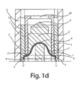
- the female contact 100 is provided with a male insulating envelope 3, 11, and an inner wall 12, said wall 12 being at least partially conductive.
- Female electrical contact 100 is provided with a safety device essentially comprised of a first protection 1 and a second protection 2, check elastic means 4 (arc or " ⁇ " spring) and two helicoidal springs 8 and 9.
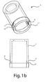
- the first protection 1 can be observed in a perspective view in figure 1b .
- it is comprised of a hollow cylinder, a fascia of its lower part, provided inside the female contact in the rest position shown in figure 1a , has a progressively reduced thickness until its truncated lower end, so as its section is trapezoidal, as it can be observed in figure 1b (part 1'). It provides notches 1" to let the ends 4' of the check elastic means passing, as it will described in the following.
- the protection 1 is not completely solid.
- the second protection 2 is of the "cylindrical type".
- it is comprised of two cylinders and of a conical tip 2'. Tip 2' partially projects with respect to the upper base of the cavity 14 of the contact 100.
- FIG 1c it is shown a preferred embodiment of the second protection, with the curved housing 2" to introduce the check means 4. It must be noted that a second part of the second protection (not shown) can be restrained in such a way to limit the movement of the check means 4, or even to block the same.
- the second protection 2 is lower than the upper base of the first protection 1.
- spring can be integral with the second protection 2, for example obtained by a single die and comprised of plastic material.
- Ends 4' of the spring engage with the two shoulders 5 of the wall 12, e.g. notches.
- Said wall 12 has a different thickness between the upper part and the lower part (lower than the spring in the rest position of the safety device).
- a part of the end 4' engages with notches 5 and another part of the ends engages with the tip 1' of the first protection 1.
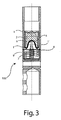
- check elastic means 4 are provided with a "cylindrical" element 6, having base 7 lower than the same check means contacting a corresponding cylindrical element 10 raising on the base 13 of the cavity 14 of the female contact, thus realising the stop of the safety device, in the position of figure 3 . It is clear that the dimensions of the parts can be chosen so as the base 7 directly contacts the bottom 13 of the cavity 14, thus eliminating the need of the presence of the cylindrical element 10.
- Cylindrical element 6 is preferably integral with the second protection 2.
- This locking can occur thanks to coupling and locking means provided on the same electrical contacts, but it is more convenient coating the same before the coupling and thus using the insulating envelopes provided with similar coupling and locking means.
- Said coupling and locking means also allow the releasing of the elements.
- said check elastic means 4 are comprised of two elements 15, joined horizontally by a spring 16. Ends of said means are engaged with the same shoulders 5 when the safety device is in the rest position and are disengaged by the first protection in the same way of the arc spring, when the male electric contact 300 is introduced within the female contact.
- the second protection 2 of figure 5 is laterally provided with said check elastic means, being the latter comprised of two lugs 17, for example returned by a spring (not shown).
- said check elastic means being the latter comprised of two lugs 17, for example returned by a spring (not shown).
- the ends of the two lugs are engaged in said shoulders 5 and are disengaged from the first protection 1.
- Buckling elastic means 23 e.g. springs
- the safety device according to the present invention particularly suitable for high power electrical contacts, it is reduced the risk of unintentional introduction of conductive materials within the female contact.
- pressure surface useful to release the safety device according to the present invention as claimed is minimum, it substantially being the section of a hollow cylinder.
- the pressure surface can be further reduced to one or two very small areas, providing the hollow cylinder with two linear projections.
Landscapes
- Details Of Connecting Devices For Male And Female Coupling (AREA)
Description
- The present invention relates to a male-female electrical connector device provided with security device.
- More specifically, the male-female electrical connector device provided with security device according to the invention as claimed is suitable to reduce the possibility of unintentional intrusion within the same electric contact, but the introduction of the male electrical contact, thanks to the use of an innovative safety device and to the use of a corresponding female electrical contact.
- Male-female kind electric connector devices are universally known, such as the connector device comprised of the jack for numerous acoustic apparatuses, or those used to load numerous electronic devices, such as the cellular phone.
- Male electric contact is usually comprised of a cylinder, or of a cylindrical crown, covered outside by metallic material.
- Female contact is a hollow cylinder having dimensions corresponding to those of the male contact, and provided inside with a conductive surface, suitable to contact the corresponding surface of the male contact as soon as the latter is properly introduced within the same female contact.
- However, for some electrical connector devices, these kind of connector devices, even working properly, are very dangerous.
- In fact, in case of high power electrical connector devices, is there a serious risk of unintentionally touching the inner conductive surface of the female contact, e.g. by the tip of a screwdriver.
- To overcome this drawback, different female contacts provided with safety devices have been proposed.
- For example, the device described in the
US patent n° 5,921,823 comprises a piston pushed by a spring inside the female contact. - In this way, when the male contact is not inserted as yet, cavity of the female contact would be protected by the piston. Unintentional contact with a conductive tip would be consequently less probable.
- However, it is to be noted that this solution according to the
US patent n° 5,921,823 is not particularly efficient. - In fact, as to the inventiveness, spring systems (or similar elastic means) for electrical connector devices were already known before the filing date of the above patent.
- For example, we can mention the
US patent n° 4,652,067 , describing an electrical connector device the female contact of which comprises a piston pushed by a spring. Said piston projects within the spring and contacts an inner conductive surface once the male contact is inserted. -
US patent n° 5,175,493 further describes a piston device released by a spring to make current tests for single elements of a circuit. -
US patent n° 5,118,301 describes a device similar to the one according toUS patent n° 4,652,067 , with a piston pushed by a spring, said spring, once pushed from outside, contacts a conductive surface within the female contact. - One skilled in the art, being aware of the male-female contacts similar to the jack type, and knowing the last three US patents, would have surely conformed the existing solutions to put the conductive surface within the female contact on the inner wall of a hollow cylinder and at the same time would have had used a piston for safety reasons, as in the first mentioned
US patent n°5,921,823 . - It is well clear that this last patent claims also particular arrangements, providing corresponding more or less innovative solutions.
- Furthermore, and in any case, the solution of this patent is not so efficient as it would seem.
- In fact, if on one side the inlet of the female contact is protected by the piston, on the other side it is not possible to use too stiff or too pre-loaded springs, otherwise it would be difficult the introduction of the male contact.
- Not being possible loading too much the springs, an unintentional movement of a conductive tip could in any case pushing the piston, contacting the inner surface of the female contact, with high risks for the device connected with the tip or, even worse, for the operator.
- Still, the Italian Patent Application n°
RM99A000137 ITRM990137 A1 - Always exploiting the principle of the piston and spring arrangement, even if in a very specific way for a particular application, device disclosed in
US patent n° 6,275,054 allows a contact between at least a pair of male-female contacts. - It is object of the present invention that of providing a male-female electrical connector device, wherein the female contact is provided with a safety device and is suitable to receive and electrically connect a male contact, solving the drawbacks and overcoming the limitations mentioned in the above.
- It is object of the present invention a safety electrical connector device as defined in
claim 1. - Preferably, according to the invention, said shoulders are cavities realised in the wall and the side of which faced toward the bottom of the cavity is oblique toward said bottom, i.e. the angle between the vertical profile of the wall and said oblique side is an obtuse angle.
- According to the invention, the wall just under said oblique side can preferably be, at least for a part of it, thinner than the wall just above said cavity, the profile of the side of the wall outward most with respect to the cavity not being modified.
- Preferably, according to the invention, said obtuse angle is between 110° and 160° sexagesimal, still more preferably between 125° and 145° sexagesimal.
- Preferably, according to the invention, said lower ends of the first protection have the side faced toward inside, opposite to the side faced toward the wall and parallel to the same, oblique, in such a way that the thickness of the lower ends reduces close to the bottom of the cavity.
- Preferably, according to the invention, the second protection is provided with an upper end so shaped to partially penetrate within said opening of the upper base of the first protection.
- Preferably, according to the invention, check elastic means are comprised of an arc spring, the arc being opened toward the cavity bottom, or of two elements joined by a spring, or of one or more lugs, laterally joined with the second protection and provided with elastic means, tending to open the same, said lugs realising, when their ends are engaged with said shoulders, in the direction of the inner part of the cavity, an acute angle with respect to the lateral profile of the second protection.
- According to the invention, it is preferable that the electric contact comprises buckling elastic means of the safety device, always pushing said safety device toward the inlet of the female electrical contact.
- Preferably, according to the invention, said buckling elastic means comprise first and second buckling means, said first buckling elastic means acting on the first protection, said second buckling means acting on the second protection.
- Preferably, according to the invention, said buckling elastic means comprise helicoidal springs.
- According to the invention, the above electric connector device preferably comprises a first stop shoulder element, integrally joined with the second protection, to make contact, at the end of stroke of the safety device within the female contact, with a corresponding second stop shoulder element joined with the bottom of said cavity.
- According to the invention, male contact and female contact can be each one provided with an insulating female casing and with an insulating male casing, said insulating casings being provided with coupling and locking means, and coupling and locking involving the introduction of the male electrical contact within the female electrical contact.
- The present invention will be now described, for illustrative but not limitative purposes, according to its preferred embodiments, with particular reference to the figures of the enclosed drawings, wherein:
-
Figure 1a is a longitudinal section of a female contact according to the invention, in the inactive configuration; -
Figure 1b is a perspective, section view of the first protection of the safety device according to the invention according tofigure 1a , projecting outside the female contact; -
Figure 1c shows two different sections and perspectives of the second protection of the safety device according to invention; -
Figure 1d shows an enlargement of a part of the female contact offigure 1a ; -
Figure 2 is a longitudinal section of the configuration of the female contact offigure 1 a when the male contact pushes the first protection for a part of its stroke, so as to release the second protection; -
Figure 3 is a longitudinal section of the piston stop and of the two protections, corresponding to the electric contact position between a male contact (not shown) and the female contact offigures 1 and2 ; -
Figure 4 shows a different embodiment of the electrical contact and of the safety device according to the invention; and -
Figure 5 shows a further different embodiment of the electrical contact and of the safety device according to the invention. - In the figures, the same reference numbers will be used for the same elements.
- Making reference to
figures 1 a and 1 d, thefemale contact 100 is provided with a male insulatingenvelope inner wall 12, saidwall 12 being at least partially conductive. Femaleelectrical contact 100 is provided with a safety device essentially comprised of afirst protection 1 and asecond protection 2, check elastic means 4 (arc or "Ω" spring) and twohelicoidal springs - The
first protection 1 can be observed in a perspective view infigure 1b . it is comprised of a hollow cylinder, a fascia of its lower part, provided inside the female contact in the rest position shown infigure 1a , has a progressively reduced thickness until its truncated lower end, so as its section is trapezoidal, as it can be observed infigure 1b (part 1'). It providesnotches 1" to let the ends 4' of the check elastic means passing, as it will described in the following. - It is also possible that the
protection 1 is not completely solid. - The
second protection 2 is of the "cylindrical type". For example, infigure 1a it is comprised of two cylinders and of a conical tip 2'. Tip 2' partially projects with respect to the upper base of thecavity 14 of thecontact 100. - In
figure 1c it is shown a preferred embodiment of the second protection, with thecurved housing 2" to introduce thecheck means 4. It must be noted that a second part of the second protection (not shown) can be restrained in such a way to limit the movement of thecheck means 4, or even to block the same. - The
second protection 2 is lower than the upper base of thefirst protection 1. -
Check means 4, that in the figure are comprised of the inverted "U" (or "Ω") spring, prevent the advancement of thesecond protection 2. - Really, spring can be integral with the
second protection 2, for example obtained by a single die and comprised of plastic material. - Ends 4' of the spring engage with the two
shoulders 5 of thewall 12, e.g. notches. Saidwall 12 has a different thickness between the upper part and the lower part (lower than the spring in the rest position of the safety device). - More specifically, in the example shown, a part of the end 4' engages with
notches 5 and another part of the ends engages with the tip 1' of thefirst protection 1. - In this way, when the
first protection 1 is pushed downward by the male contact, tips 1' push the check means 4, said check means contracting horizontally up to sliding along the oblique side of the trapezoidal section tips 1', as shown infigure 2 . - Now, prosecuting the pushing action on the
first protection 1 and on the conical tip 2' of thesecond protection 2, check means 4 and the safety device is moved downward, buckling the elastic force of the twosprings - In any case, check
elastic means 4 are provided with a "cylindrical"element 6, havingbase 7 lower than the same check means contacting a correspondingcylindrical element 10 raising on thebase 13 of thecavity 14 of the female contact, thus realising the stop of the safety device, in the position offigure 3 . It is clear that the dimensions of the parts can be chosen so as thebase 7 directly contacts the bottom 13 of thecavity 14, thus eliminating the need of the presence of thecylindrical element 10. -
Cylindrical element 6 is preferably integral with thesecond protection 2. - In correspondence of the stop position of the
element 6 against theelement 10, it is obtained the complete activation of the locking device of the male contact within the female contact. - This locking can occur thanks to coupling and locking means provided on the same electrical contacts, but it is more convenient coating the same before the coupling and thus using the insulating envelopes provided with similar coupling and locking means.
- Advantageously, it is possible to use a female insulating element for the male contact and a male insulating envelope for the female contact, as those disclosed in
US patent 5,685,730 . - Said coupling and locking means also allow the releasing of the elements.
- It is to be noted that according to the present invention as claimed it is possible to provide solutions for the check means 4 different with respect to the arc spring.
- As it appears from
figure 4 , said checkelastic means 4 are comprised of twoelements 15, joined horizontally by a spring 16. Ends of said means are engaged with thesame shoulders 5 when the safety device is in the rest position and are disengaged by the first protection in the same way of the arc spring, when the maleelectric contact 300 is introduced within the female contact. - As further example, the
second protection 2 offigure 5 is laterally provided with said check elastic means, being the latter comprised of twolugs 17, for example returned by a spring (not shown). In this case too, the ends of the two lugs are engaged in saidshoulders 5 and are disengaged from thefirst protection 1. Buckling elastic means 23 (e.g. springs) are laterally provided between the first 1 and the second 2 protection. - In all the previous embodiments, in the female contact there are distingushed the
part 100, with thecavity 14, from thepart 200, containing afurther cavity 20, within which the electrical wires are inserted and fixed by suitable fixing means, even through theopenings 21. - In this way, the above different embodiments are interchangeable with respect to the
same part 200. - Thanks to the safety device according to the present invention, particularly suitable for high power electrical contacts, it is reduced the risk of unintentional introduction of conductive materials within the female contact.
- In fact, pressure surface useful to release the safety device according to the present invention as claimed is minimum, it substantially being the section of a hollow cylinder. However, the pressure surface can be further reduced to one or two very small areas, providing the hollow cylinder with two linear projections.
- The present invention has been described for illustrative but not limitative purposes, according to its preferred embodiments, but it is to be understood that modifications and/or changes can be introduced by those skilled in the art without departing from the relevant scope as defined in the enclosed claims.
Claims (15)
- Safety electrical connector device, comprising a male electrical connector (300) and a female electrical connector (100) both having a longitudinal extension axis and being coaxial with respect to said longitudinal extension axis, wherein- the female electrical connector being provided with a cavity (14) having a cavity opening and a cavity closed end (13) opposite to the opening along said longitudinal extension axis,- said cavity (14) being delimited laterally with respect to said longitudinal extension axis by an at least partly electrically conductive wall (12),- the female electrical connector being further provided with a coaxial safety device,
said safety electrical connector device being characterised in that the coaxial safety device comprises:- a first protection (1) extended along said longitudinal extension axis and having first end towards said cavity opening and second end towards said cavity closed end (13), the first and second ends being open, and- a second protection (2) extended along said longitudinal extension axis and provided inside the first protection (1),
said safety device further comprising check elastic means (4), diametrically occupying all the cavity (14), and fixed to said second protection (2), said elastic means being provided with ends (4') that are, in a rest position, partially engaged with shoulders (5) realised on the inner side of the wall (12) and partially contacting said second end (1') of the first protection (1), the check elastic means (4) exerting an elastic force against the wall (12) in correspondence of said shoulders (5), so that, when the first protection (1) is pushed inward the cavity (14) along said longitudinal extension axis by the male electrical connector, check elastic means (4) engage with said second end (1') and are consequently disengaged from said shoulders (5), and the safety device is integrally moved toward said cavity closed end (13). - Safety electrical connector device according to claim 1, characterised in that it comprises buckling elastic means (8, 9) for the safety device, pushing said safety device always toward said cavity opening of the female electrical connector (100).
- Safety electrical connector device according to claim 2, characterised in that said buckling elastic means (8, 9) comprise a first and a second buckling elastic means, said first buckling elastic means (8) acting on the first protection (1), said second buckling elastic means (9) acting on the second protection (2).
- Safety electrical connector device according to claim 2 or 3, characterised in that said buckling elastic means (8, 9) comprise helicoidal springs.
- Safety electrical connector device according to any of claims 1 to 4, characterised in that said shoulders (5) are cavities realised in the wall (12) and have a last portion (5') toward said cavity closed end (13) that presents an obtuse angle with respect to the profile of the wall (12) parallel to said longitudinal extension axis.
- Safety electrical connector device according to claim 5, characterised in that the wall (12) just after said last portion (5') toward said cavity closed end (13) is , at least partially, thinner than the wall (12) just before said last portion (5').
- Safety electrical connector device according to claim 5 or 6, characterised in that said obtuse angle is between 110° and 160° sexagesimal.
- Safety electrical connector device according to claim 6, characterised in that said obtuse angle is between 125° and 145° sexagesimal.
- Safety electrical connector device according to any of claims 1 to 8, characterised in that said second end (1') of the first protection (1) is wedge-shaped, in such a way that the thickness of the lower ends (1') reduces towards said cavity closed end (13).
- Safety electrical connector device according to claim 1, characterised in that the second protection (2) is provided with a first end (2') towards said cavity opening that is so shaped to partially penetrate within said first end of the first protection (1), when the male electrical connector is not inserted in the female electrical connector.
- Safety electrical connector device according to any of claims 1 to 10, characterised in that said check elastic means (4) are comprised of an arc spring, the arc being opened toward the cavity closed end (13).
- Safety electrical connector device according to any of claims 1 to 10, characterised in that said check elastic means (4) are comprised of two elements (15) joined by a spring (16).
- Safety electrical connector device according to any of claims 1 to 10, characterised in that said check elastic means (4) are comprised of one or more lugs (17), laterally joined with the second protection (2) and provided with elastic means, tending to open the same with respect to the second protection (2), said lugs (17) realising, when their ends are engaged with said shoulders (5), towards said cavity closed end (13), an acute angle with respect to said longitudinal extension axis.
- Safety electrical connector device according to any of claims 1 to 13, characterised in that it comprises a first stop shoulder element (6), integrally joined with the second protection, to make contact, at the end of stroke of the safety device within the female connector (100), with a corresponding second stop shoulder element (10) joined with the bottom (13) of said cavity (14) at said cavity closed end (13).
- Safety electrical connector device according to any of the preceding claims, characterised in that the male electrical connector and the female electrical connector are respectively provided with an insulating female casing and with an insulating male casing, said insulating casings being provided with coupling and locking means, and coupling and locking involving the introduction of the male electrical connector within the female electrical connector.
Applications Claiming Priority (2)
| Application Number | Priority Date | Filing Date | Title |
|---|---|---|---|
| ITRM20030306 | 2003-06-20 | ||
| IT000306A ITRM20030306A1 (en) | 2003-06-20 | 2003-06-20 | MALE-FEMALE ELECTRIC CONTACT WITH SAFETY DEVICE, SAFETY DEVICE AND FEMALE ELECTRIC CONTACT TO BE USED |
Publications (2)
| Publication Number | Publication Date |
|---|---|
| EP1489700A1 EP1489700A1 (en) | 2004-12-22 |
| EP1489700B1 true EP1489700B1 (en) | 2013-09-04 |
Family
ID=29765879
Family Applications (1)
| Application Number | Title | Priority Date | Filing Date |
|---|---|---|---|
| EP04425430.8A Expired - Lifetime EP1489700B1 (en) | 2003-06-20 | 2004-06-11 | Safety connector arrangement |
Country Status (2)
| Country | Link |
|---|---|
| EP (1) | EP1489700B1 (en) |
| IT (1) | ITRM20030306A1 (en) |
Families Citing this family (3)
| Publication number | Priority date | Publication date | Assignee | Title |
|---|---|---|---|---|
| EP2696446B1 (en) | 2012-08-09 | 2015-04-15 | Valentini S.N.C. Di Badella R. & Creazzo S. | Improved female contact for electric safety connector |
| JP6355155B2 (en) * | 2014-04-24 | 2018-07-11 | 株式会社オーディオテクニカ | Condenser microphone |
| CN107819215B (en) * | 2016-09-14 | 2024-04-09 | 泰科电子(上海)有限公司 | Connector |
Family Cites Families (8)
| Publication number | Priority date | Publication date | Assignee | Title |
|---|---|---|---|---|
| US4652067A (en) | 1985-12-06 | 1987-03-24 | Switchcraft, Inc. | Electrical connector with an internal switch |
| US5118301A (en) | 1991-05-02 | 1992-06-02 | Valentino Bentivolio | Electrical connector device |
| US5175493A (en) | 1991-10-11 | 1992-12-29 | Interconnect Devices, Inc. | Shielded electrical contact spring probe assembly |
| GB2308244B (en) * | 1992-09-02 | 1997-08-20 | Otter Controls Ltd | Improvements relating to electrical appliances and connectors therefor |
| US5685730A (en) | 1996-03-15 | 1997-11-11 | Litton Precision Products International, Inc. | Power connector set with secondary lock |
| US5921823A (en) | 1997-08-01 | 1999-07-13 | Litton Systems, Inc. | Dead-front high current female power contact |
| AU1820900A (en) | 1998-11-25 | 2000-06-13 | Rika Electronics International, Inc. | Electrical contact system |
| IT1306794B1 (en) | 1999-03-03 | 2001-10-02 | Link S R L | SAFETY DEVICE FOR MALE CONNECTOR PROVIDED WITH FEMALE CONTACT. |
-
2003
- 2003-06-20 IT IT000306A patent/ITRM20030306A1/en unknown
-
2004
- 2004-06-11 EP EP04425430.8A patent/EP1489700B1/en not_active Expired - Lifetime
Also Published As
| Publication number | Publication date |
|---|---|
| ITRM20030306A0 (en) | 2003-06-20 |
| ITRM20030306A1 (en) | 2004-12-21 |
| EP1489700A1 (en) | 2004-12-22 |
Similar Documents
| Publication | Publication Date | Title |
|---|---|---|
| CN101325298B (en) | Connector plug | |
| US9368897B2 (en) | Electrical connector | |
| US5505631A (en) | Device to connect an explosive charge with an electric current source | |
| CN101218714B (en) | Connector Assemblies with Terminal Position Assurance Devices | |
| JP2009544127A (en) | Plug-in type surge protection combination device | |
| CN106463882B (en) | Cable strain relief | |
| CN102237231A (en) | Device for holding a fuse and switching device | |
| CN100413156C (en) | Connector | |
| US8944836B2 (en) | Wire line connector | |
| EP0999952B1 (en) | Squib connector | |
| EP3376609B1 (en) | Female connector and connection structure of female connector and male connector | |
| EP1489700A1 (en) | Safety connector arrangement | |
| EP2240983B1 (en) | Locking electrical receptacle | |
| CN106953214B (en) | Connector plug with two groups of different current pin groups | |
| EP1225656A3 (en) | Electrical connector assembly | |
| EP2360794B1 (en) | Connector | |
| CN103715028A (en) | Connector and method for connecting installation switching devices | |
| CN102694306A (en) | Pluggable modules having latch mechanisms for gripping receptacle assemblies | |
| WO2008084339A1 (en) | Electrical connector assembly with improved locking means | |
| CN210692846U (en) | Terminal sheath structure | |
| US5605478A (en) | Means for attaching a connector body to an electric device | |
| CN206774597U (en) | Battery fastening structure | |
| US6488518B2 (en) | Squibb electronic connector | |
| CN209929208U (en) | Fuse type isolating switch | |
| AU6968900A (en) | Safety device for a contact strip |
Legal Events
| Date | Code | Title | Description |
|---|---|---|---|
| PUAI | Public reference made under article 153(3) epc to a published international application that has entered the european phase |
Free format text: ORIGINAL CODE: 0009012 |
|
| AK | Designated contracting states |
Kind code of ref document: A1 Designated state(s): AT BE BG CH CY CZ DE DK EE ES FI FR GB GR HU IE IT LI LU MC NL PL PT RO SE SI SK TR |
|
| AX | Request for extension of the european patent |
Extension state: AL HR LT LV MK |
|
| 17P | Request for examination filed |
Effective date: 20050524 |
|
| AKX | Designation fees paid |
Designated state(s): AT BE BG CH CY CZ DE DK EE ES FI FR GB GR HU IE IT LI LU MC NL PL PT RO SE SI SK TR |
|
| 17Q | First examination report despatched |
Effective date: 20120801 |
|
| GRAP | Despatch of communication of intention to grant a patent |
Free format text: ORIGINAL CODE: EPIDOSNIGR1 |
|
| INTG | Intention to grant announced |
Effective date: 20130404 |
|
| RIN1 | Information on inventor provided before grant (corrected) |
Inventor name: NISI, ANDREA, Inventor name: PRIORI, CLAUDIO, Inventor name: PIROMALLI, MARCO, |
|
| GRAS | Grant fee paid |
Free format text: ORIGINAL CODE: EPIDOSNIGR3 |
|
| GRAA | (expected) grant |
Free format text: ORIGINAL CODE: 0009210 |
|
| AK | Designated contracting states |
Kind code of ref document: B1 Designated state(s): AT BE BG CH CY CZ DE DK EE ES FI FR GB GR HU IE IT LI LU MC NL PL PT RO SE SI SK TR |
|
| REG | Reference to a national code |
Ref country code: GB Ref legal event code: FG4D |
|
| REG | Reference to a national code |
Ref country code: CH Ref legal event code: EP |
|
| REG | Reference to a national code |
Ref country code: AT Ref legal event code: REF Ref document number: 630942 Country of ref document: AT Kind code of ref document: T Effective date: 20130915 |
|
| REG | Reference to a national code |
Ref country code: IE Ref legal event code: FG4D |
|
| REG | Reference to a national code |
Ref country code: DE Ref legal event code: R096 Ref document number: 602004043225 Country of ref document: DE Effective date: 20131031 |
|
| REG | Reference to a national code |
Ref country code: AT Ref legal event code: MK05 Ref document number: 630942 Country of ref document: AT Kind code of ref document: T Effective date: 20130904 |
|
| REG | Reference to a national code |
Ref country code: NL Ref legal event code: VDEP Effective date: 20130904 |
|
| PG25 | Lapsed in a contracting state [announced via postgrant information from national office to epo] |
Ref country code: SE Free format text: LAPSE BECAUSE OF FAILURE TO SUBMIT A TRANSLATION OF THE DESCRIPTION OR TO PAY THE FEE WITHIN THE PRESCRIBED TIME-LIMIT Effective date: 20130904 Ref country code: CY Free format text: LAPSE BECAUSE OF FAILURE TO SUBMIT A TRANSLATION OF THE DESCRIPTION OR TO PAY THE FEE WITHIN THE PRESCRIBED TIME-LIMIT Effective date: 20130703 Ref country code: AT Free format text: LAPSE BECAUSE OF FAILURE TO SUBMIT A TRANSLATION OF THE DESCRIPTION OR TO PAY THE FEE WITHIN THE PRESCRIBED TIME-LIMIT Effective date: 20130904 |
|
| REG | Reference to a national code |
Ref country code: NL Ref legal event code: VDEP Effective date: 20130904 |
|
| PG25 | Lapsed in a contracting state [announced via postgrant information from national office to epo] |
Ref country code: GR Free format text: LAPSE BECAUSE OF FAILURE TO SUBMIT A TRANSLATION OF THE DESCRIPTION OR TO PAY THE FEE WITHIN THE PRESCRIBED TIME-LIMIT Effective date: 20131205 Ref country code: PL Free format text: LAPSE BECAUSE OF FAILURE TO SUBMIT A TRANSLATION OF THE DESCRIPTION OR TO PAY THE FEE WITHIN THE PRESCRIBED TIME-LIMIT Effective date: 20130904 Ref country code: FI Free format text: LAPSE BECAUSE OF FAILURE TO SUBMIT A TRANSLATION OF THE DESCRIPTION OR TO PAY THE FEE WITHIN THE PRESCRIBED TIME-LIMIT Effective date: 20130904 Ref country code: SI Free format text: LAPSE BECAUSE OF FAILURE TO SUBMIT A TRANSLATION OF THE DESCRIPTION OR TO PAY THE FEE WITHIN THE PRESCRIBED TIME-LIMIT Effective date: 20130904 |
|
| PG25 | Lapsed in a contracting state [announced via postgrant information from national office to epo] |
Ref country code: CY Free format text: LAPSE BECAUSE OF FAILURE TO SUBMIT A TRANSLATION OF THE DESCRIPTION OR TO PAY THE FEE WITHIN THE PRESCRIBED TIME-LIMIT Effective date: 20130904 Ref country code: BE Free format text: LAPSE BECAUSE OF FAILURE TO SUBMIT A TRANSLATION OF THE DESCRIPTION OR TO PAY THE FEE WITHIN THE PRESCRIBED TIME-LIMIT Effective date: 20130904 |
|
| PG25 | Lapsed in a contracting state [announced via postgrant information from national office to epo] |
Ref country code: EE Free format text: LAPSE BECAUSE OF FAILURE TO SUBMIT A TRANSLATION OF THE DESCRIPTION OR TO PAY THE FEE WITHIN THE PRESCRIBED TIME-LIMIT Effective date: 20130904 Ref country code: NL Free format text: LAPSE BECAUSE OF FAILURE TO SUBMIT A TRANSLATION OF THE DESCRIPTION OR TO PAY THE FEE WITHIN THE PRESCRIBED TIME-LIMIT Effective date: 20130904 Ref country code: SK Free format text: LAPSE BECAUSE OF FAILURE TO SUBMIT A TRANSLATION OF THE DESCRIPTION OR TO PAY THE FEE WITHIN THE PRESCRIBED TIME-LIMIT Effective date: 20130904 Ref country code: CZ Free format text: LAPSE BECAUSE OF FAILURE TO SUBMIT A TRANSLATION OF THE DESCRIPTION OR TO PAY THE FEE WITHIN THE PRESCRIBED TIME-LIMIT Effective date: 20130904 Ref country code: RO Free format text: LAPSE BECAUSE OF FAILURE TO SUBMIT A TRANSLATION OF THE DESCRIPTION OR TO PAY THE FEE WITHIN THE PRESCRIBED TIME-LIMIT Effective date: 20130904 |
|
| PG25 | Lapsed in a contracting state [announced via postgrant information from national office to epo] |
Ref country code: ES Free format text: LAPSE BECAUSE OF FAILURE TO SUBMIT A TRANSLATION OF THE DESCRIPTION OR TO PAY THE FEE WITHIN THE PRESCRIBED TIME-LIMIT Effective date: 20130904 |
|
| REG | Reference to a national code |
Ref country code: DE Ref legal event code: R097 Ref document number: 602004043225 Country of ref document: DE |
|
| PG25 | Lapsed in a contracting state [announced via postgrant information from national office to epo] |
Ref country code: PT Free format text: LAPSE BECAUSE OF FAILURE TO SUBMIT A TRANSLATION OF THE DESCRIPTION OR TO PAY THE FEE WITHIN THE PRESCRIBED TIME-LIMIT Effective date: 20140106 |
|
| PLBE | No opposition filed within time limit |
Free format text: ORIGINAL CODE: 0009261 |
|
| STAA | Information on the status of an ep patent application or granted ep patent |
Free format text: STATUS: NO OPPOSITION FILED WITHIN TIME LIMIT |
|
| 26N | No opposition filed |
Effective date: 20140605 |
|
| REG | Reference to a national code |
Ref country code: DE Ref legal event code: R097 Ref document number: 602004043225 Country of ref document: DE Effective date: 20140605 |
|
| PG25 | Lapsed in a contracting state [announced via postgrant information from national office to epo] |
Ref country code: DK Free format text: LAPSE BECAUSE OF FAILURE TO SUBMIT A TRANSLATION OF THE DESCRIPTION OR TO PAY THE FEE WITHIN THE PRESCRIBED TIME-LIMIT Effective date: 20130904 |
|
| PG25 | Lapsed in a contracting state [announced via postgrant information from national office to epo] |
Ref country code: LU Free format text: LAPSE BECAUSE OF FAILURE TO SUBMIT A TRANSLATION OF THE DESCRIPTION OR TO PAY THE FEE WITHIN THE PRESCRIBED TIME-LIMIT Effective date: 20140611 Ref country code: MC Free format text: LAPSE BECAUSE OF FAILURE TO SUBMIT A TRANSLATION OF THE DESCRIPTION OR TO PAY THE FEE WITHIN THE PRESCRIBED TIME-LIMIT Effective date: 20130904 |
|
| REG | Reference to a national code |
Ref country code: CH Ref legal event code: PL |
|
| REG | Reference to a national code |
Ref country code: IE Ref legal event code: MM4A |
|
| PG25 | Lapsed in a contracting state [announced via postgrant information from national office to epo] |
Ref country code: LI Free format text: LAPSE BECAUSE OF NON-PAYMENT OF DUE FEES Effective date: 20140630 Ref country code: CH Free format text: LAPSE BECAUSE OF NON-PAYMENT OF DUE FEES Effective date: 20140630 Ref country code: IE Free format text: LAPSE BECAUSE OF NON-PAYMENT OF DUE FEES Effective date: 20140611 |
|
| REG | Reference to a national code |
Ref country code: FR Ref legal event code: PLFP Year of fee payment: 13 |
|
| PG25 | Lapsed in a contracting state [announced via postgrant information from national office to epo] |
Ref country code: BG Free format text: LAPSE BECAUSE OF FAILURE TO SUBMIT A TRANSLATION OF THE DESCRIPTION OR TO PAY THE FEE WITHIN THE PRESCRIBED TIME-LIMIT Effective date: 20130904 |
|
| PG25 | Lapsed in a contracting state [announced via postgrant information from national office to epo] |
Ref country code: TR Free format text: LAPSE BECAUSE OF FAILURE TO SUBMIT A TRANSLATION OF THE DESCRIPTION OR TO PAY THE FEE WITHIN THE PRESCRIBED TIME-LIMIT Effective date: 20130904 Ref country code: HU Free format text: LAPSE BECAUSE OF FAILURE TO SUBMIT A TRANSLATION OF THE DESCRIPTION OR TO PAY THE FEE WITHIN THE PRESCRIBED TIME-LIMIT; INVALID AB INITIO Effective date: 20040611 |
|
| REG | Reference to a national code |
Ref country code: FR Ref legal event code: PLFP Year of fee payment: 14 |
|
| REG | Reference to a national code |
Ref country code: FR Ref legal event code: PLFP Year of fee payment: 15 |
|
| REG | Reference to a national code |
Ref country code: FR Ref legal event code: PLFP Year of fee payment: 20 |
|
| REG | Reference to a national code |
Ref country code: DE Ref legal event code: R081 Ref document number: 602004043225 Country of ref document: DE Owner name: LINK SRL, IT Free format text: FORMER OWNER: LINK SRL, ROMA, IT |
|
| PGFP | Annual fee paid to national office [announced via postgrant information from national office to epo] |
Ref country code: IT Payment date: 20230615 Year of fee payment: 20 Ref country code: FR Payment date: 20230411 Year of fee payment: 20 Ref country code: DE Payment date: 20230418 Year of fee payment: 20 |
|
| PGFP | Annual fee paid to national office [announced via postgrant information from national office to epo] |
Ref country code: GB Payment date: 20230420 Year of fee payment: 20 |
|
| REG | Reference to a national code |
Ref country code: DE Ref legal event code: R071 Ref document number: 602004043225 Country of ref document: DE |
|
| PG25 | Lapsed in a contracting state [announced via postgrant information from national office to epo] |
Ref country code: GB Free format text: LAPSE BECAUSE OF EXPIRATION OF PROTECTION Effective date: 20240610 |
|
| PG25 | Lapsed in a contracting state [announced via postgrant information from national office to epo] |
Ref country code: GB Free format text: LAPSE BECAUSE OF EXPIRATION OF PROTECTION Effective date: 20240610 |