EP1489611A1 - Wobble demodulation for high density optical recording media - Google Patents
Wobble demodulation for high density optical recording media Download PDFInfo
- Publication number
- EP1489611A1 EP1489611A1 EP03013620A EP03013620A EP1489611A1 EP 1489611 A1 EP1489611 A1 EP 1489611A1 EP 03013620 A EP03013620 A EP 03013620A EP 03013620 A EP03013620 A EP 03013620A EP 1489611 A1 EP1489611 A1 EP 1489611A1
- Authority
- EP
- European Patent Office
- Prior art keywords
- msk
- wobble signal
- wobble
- demodulation
- carrier
- Prior art date
- Legal status (The legal status is an assumption and is not a legal conclusion. Google has not performed a legal analysis and makes no representation as to the accuracy of the status listed.)
- Withdrawn
Links
- 230000003287 optical effect Effects 0.000 title claims abstract description 16
- 102100031830 Afadin- and alpha-actinin-binding protein Human genes 0.000 claims abstract description 39
- 101710182459 Afadin- and alpha-actinin-binding protein Proteins 0.000 claims abstract description 39
- 238000000034 method Methods 0.000 claims abstract description 39
- 238000001514 detection method Methods 0.000 description 11
- 230000001427 coherent effect Effects 0.000 description 7
- 238000007476 Maximum Likelihood Methods 0.000 description 3
- XUIMIQQOPSSXEZ-UHFFFAOYSA-N Silicon Chemical compound [Si] XUIMIQQOPSSXEZ-UHFFFAOYSA-N 0.000 description 3
- 230000036316 preload Effects 0.000 description 3
- 229910052710 silicon Inorganic materials 0.000 description 3
- 239000010703 silicon Substances 0.000 description 3
- WYTGDNHDOZPMIW-RCBQFDQVSA-N alstonine Natural products C1=CC2=C3C=CC=CC3=NC2=C2N1C[C@H]1[C@H](C)OC=C(C(=O)OC)[C@H]1C2 WYTGDNHDOZPMIW-RCBQFDQVSA-N 0.000 description 2
- 230000015556 catabolic process Effects 0.000 description 2
- 238000006731 degradation reaction Methods 0.000 description 2
- 238000001914 filtration Methods 0.000 description 2
- 230000006872 improvement Effects 0.000 description 2
- 230000010363 phase shift Effects 0.000 description 2
- 230000008569 process Effects 0.000 description 2
- 230000009467 reduction Effects 0.000 description 2
- LKJPSUCKSLORMF-UHFFFAOYSA-N Monolinuron Chemical compound CON(C)C(=O)NC1=CC=C(Cl)C=C1 LKJPSUCKSLORMF-UHFFFAOYSA-N 0.000 description 1
- 238000004458 analytical method Methods 0.000 description 1
- 230000008859 change Effects 0.000 description 1
- 238000010586 diagram Methods 0.000 description 1
- 230000000694 effects Effects 0.000 description 1
- 238000005259 measurement Methods 0.000 description 1
Images


Classifications
-
- G—PHYSICS
- G11—INFORMATION STORAGE
- G11B—INFORMATION STORAGE BASED ON RELATIVE MOVEMENT BETWEEN RECORD CARRIER AND TRANSDUCER
- G11B20/00—Signal processing not specific to the method of recording or reproducing; Circuits therefor
- G11B20/10—Digital recording or reproducing
-
- G—PHYSICS
- G11—INFORMATION STORAGE
- G11B—INFORMATION STORAGE BASED ON RELATIVE MOVEMENT BETWEEN RECORD CARRIER AND TRANSDUCER
- G11B27/00—Editing; Indexing; Addressing; Timing or synchronising; Monitoring; Measuring tape travel
- G11B27/10—Indexing; Addressing; Timing or synchronising; Measuring tape travel
- G11B27/19—Indexing; Addressing; Timing or synchronising; Measuring tape travel by using information detectable on the record carrier
-
- G—PHYSICS
- G11—INFORMATION STORAGE
- G11B—INFORMATION STORAGE BASED ON RELATIVE MOVEMENT BETWEEN RECORD CARRIER AND TRANSDUCER
- G11B27/00—Editing; Indexing; Addressing; Timing or synchronising; Monitoring; Measuring tape travel
- G11B27/10—Indexing; Addressing; Timing or synchronising; Measuring tape travel
- G11B27/19—Indexing; Addressing; Timing or synchronising; Measuring tape travel by using information detectable on the record carrier
- G11B27/24—Indexing; Addressing; Timing or synchronising; Measuring tape travel by using information detectable on the record carrier by sensing features on the record carrier other than the transducing track ; sensing signals or marks recorded by another method than the main recording
-
- G—PHYSICS
- G11—INFORMATION STORAGE
- G11B—INFORMATION STORAGE BASED ON RELATIVE MOVEMENT BETWEEN RECORD CARRIER AND TRANSDUCER
- G11B27/00—Editing; Indexing; Addressing; Timing or synchronising; Monitoring; Measuring tape travel
- G11B27/10—Indexing; Addressing; Timing or synchronising; Measuring tape travel
- G11B27/19—Indexing; Addressing; Timing or synchronising; Measuring tape travel by using information detectable on the record carrier
- G11B27/28—Indexing; Addressing; Timing or synchronising; Measuring tape travel by using information detectable on the record carrier by using information signals recorded by the same method as the main recording
- G11B27/30—Indexing; Addressing; Timing or synchronising; Measuring tape travel by using information detectable on the record carrier by using information signals recorded by the same method as the main recording on the same track as the main recording
- G11B27/3027—Indexing; Addressing; Timing or synchronising; Measuring tape travel by using information detectable on the record carrier by using information signals recorded by the same method as the main recording on the same track as the main recording used signal is digitally coded
Definitions
- the present invention relates to a method for the demodulation of the ADIP data of a wobble signal of an optical recording medium, and to an apparatus for reading from and/or writing to optical recording media using such method.
- Methods such as these are used, for example, in an apparatus for reading from and/or writing to optical recording media having wobbled tracks, in order to obtain address information from the wobbled tracks (ADIP information, address in pregroove) or to use the wobble frequency to produce a write clock.
- ADIP information address information from the wobbled tracks
- wobble frequency to produce a write clock.
- the tracks are formed such that they represent an interleaved spiral or concentric circles.
- the tracks additionally are wobbled in a specific form, in order to find specific positions on the medium.
- the track is not an approximately straight line, but a serpentine line.
- the shape of this serpentine line can contain address information, which is used for identifying a specific position on this optical recording medium.
- Various methods are used for coding, examples of which include frequency modulation or phase modulation.
- the wobble signal may also be used for rotation speed information or for presetting a write data rate.
- the two methods are not used separately for synchronization and ADIP information, as illustrated in the Fig. 3, which shows the different units ocurring in an ADIP word.
- the ADIP word another MSK mark is added at different locations, for the data_0 unit at the wobble periods 14,15, and 16, and for the data_1 unit at the wobble periods 12,13, and 14. Therefore, MSK marks could be used also for ADIP data demodulation.
- some ADIP units, the so-called reference units also have the second harmonic wobble frequency. In this case, the second harmonic has a fixed phase shift, so the reference unit could be used for the synchronization of the ADIP nibble.
- a method for the demodulation of the ADIP data of a wobble signal of an optical recording medium, whereby the wobble signal is modulated using two different methods comprises the steps of
- the method is applied to a wobble signal which is modulated using the methods of minimum shift keying (MSK) and harmonic modulated wave (HMW). Since such a wobble modulation has been proposed for high density optical recording media, a method capable of demodulating this type of wobble signal will become important.
- MSK minimum shift keying
- HMW harmonic modulated wave
- a combination of MSK demodulation and HMW demodulation is used for demodulating the down-converted data, the combination being based on the locations of the MSK marks.
- the detection can either use the location of the MSK mark or the phase of the second harmonic. The best result, however, is achieved by using both demodulations.
- the sampled output of an MSK filter detector and the sampled output of an HMW accumulator are properly mixed.
- the step of down-converting the modulated data to the base band comprises using three distinct correlation paths. Two correlation paths are used for generating signals necessary for the detection of MSK marks. The third correlation path generates a signal which allows to detect a modulation in accordance with the HMW method.
- the three distinct correlation paths correlate to the in-phase carrier, the second harmonic of the carrier, and the 1.5 frequency of the carrier, respectively. These are the frequencies which are necessary in order to detect wobbles modulated in accordance with the proposed MSK and the HMW methods. Of course, depending on the specific modulation, other frequencies are also suitable.
- At least two of the correlation paths share components. This leads to a reduction of the implementation cost (in terms of silicon area) .
- Possible shared components are sin/cos generators, multipliers and integrate & dumps.
- a device for demodulating the ADIP data of a wobble signal of an optical recording medium, whereby the wobble signal is modulated using two different methods performs a method according to the invention.
- a method according to the invention is performed by an apparatus for reading from and/or writing to optical recording media for wobble demodulation.
- Such an apparatus has an increased performance compared with an apparatus using only pure frequency demodulation or pure phase demodulation, since hardly any signal energy is lost.
- Fig. 4 a coherent demodulator 1 according to the invention is shown.
- the demodulator 1 it is worth to consider that:
- the block diagram in Fig. 4 represents the demodulator 1, which includes the PLL 2, a down-converter 3 and a base band demodulator 4.
- the down-converter 3 converts the modulated data to the base-band. It includes three sub-paths 31, 32, 33. Each one is a correlator over the wobble periods.
- the first sub-path 31 correlates the in-phase carrier, the second one 32 correlates the second harmonic frequency and the third one 33 correlates the 1.5 frequency of the MSK mark.
- the expression ⁇ t represents 2 ⁇ f wob t.
- a digital controlled oscillator (DCO) 21 is used instead of a voltage controlled oscillator (VCO).
- the in-phase and the quadrature sinusoidal waveforms are generated by means of computations (for example through a Cordic algorithm) or look-up tables.
- the integrate & dump blocks 34, 35, 36 are resettable accumulators with a sample and hold. The data rate of the output of each correlator is equal to the frequency of the wobble.
- the behaviour of the down-converter 3 can be easily analysed.
- the wobble period is normalized to 1, that the wobble amplitude is equal to 1, and that the amplitude of the sinusoidal waveforms (fundamental frequency and 1.5 frequency) generated in the demodulator 1 is equal to 2 and the amplitude of the second harmonic generated in the demodulator 1 is equal to 0.5, i.e. 4 times smaller than the amplitude of the fundamental frequency. All following numbers are based on this exemplary values. Using other values, different numbers are obtained.
- the output of the correlators is equal to 1 when the same frequency is received with the same phase, -1 when the same frequency is received with a 180° phase shift, and 0 otherwise.
- the signals I1 and I1h are given by the streams in the following Table 1 : MW MW MW MSK MSK MSK MW MW MW I1 1 1 1 0 -1 0 1 1 1 I1h 0 0 0 1 0 -1 0 0 0 0 0 0 0 0 0 0 0
- FIG. 5 shows a scheme of the base band demodulator 4, which processes the base band signal to detect the proper data synchronization and to recognize the bit values of the ADIP words.
- the base band demodulator 4 includes the following functional blocks:
- the MSK filter 5 applies a proper filtering to the signals I1 and I1h for improving the detection of the MSK phase for the wobble periods 0-55 within the ADIP unit, considering the degradation due to the input noise.
- the HMW accumulator 6 improves the noise rejection of HMW demodulation by integrating the base band signal over several wobble periods, precisely the wobble periods 18-54. For this purpose it needs a proper timing.
- the time generator 7 includes two counters, namely a wobble counter [0-55] locked to the ADIP unit and an ADIP unit counter [0-82] locked to the ADIP word. Moreover, the time generator 7 provides all timing signals which are necessary for other parts. These signals are proper Boolean combinations of the abovementioned counters.
- the Sync detector 8 performs the synchronization process in order to lock the time generator 7 to the ADIP unit and the ADIP word.
- the ADIP bit detector 9 samples the output of the MSK filter 5 and the HMW accumulator 6 to obtain the amplitude of the MSK mark and the amplitude of the harmonic.
- the filter 5 has six possible values of input signals I1 and I1h. They are:
- the filter 5 should distinguish as much as possible W from M0. Therefore, the maximum likelihood MSK Mark detector should decide W or M0 by measuring the Euclidean distance of the received signal R from W and from M0. The decision is based on the minimum distance. The decision is equivalent to the measurement of the correlation with the difference value M0-W, so the best filter MF should match to the difference of the two values: where tr stands for "time reversed". Considering the input stream of Table 1, this matched filter gives the following results as summarized in Table 2 : MW MW MW MSK MSK MSK MW MW MW MF out 4 4 4 4 4 0 -4 0 4 4
- the peak at -4 corresponds to the end of the MSK mark. It is apparent that the location of the MSK mark can be detected by searching the peak at -4.
- the output of the above filter 5 minimizes the probability of detecting W instead of M0 and vice versa.
- the signal looks like the MSK mark in Figure 3. Where there is a MSK mark the signal is 0 -4 0, with a delay of a wobble period, otherwise it is equal to 4.
- the Sync detector 8 receives the output of the MSK filter 5 and manages two counters of the time generator 7 by preloading them in the proper way.
- the Sync detector 8 is a state machine combined with an MSK mark detector.
- the MSK mark detector is a threshold detector, which detects an MSK mark when the signal is under the threshold -2.
- the inputs of the state machine are the addresses of the time generator counters and the detected MSK mark.
- the main states of the state machine are:
- the detection can either use the location of the MSK mark or the phase of the second harmonic.
- the best detector uses both by properly mixing the sampled output of the MSK filter 5 at the wobbles number 14 and 16 and the sampled output of the HMW accumulator 6 at the location 54.
- the amplitude of the signals from the MSK filter 5 and the HMW accumulator 6 must be balanced, normalizing the effect of the MSK filter 5 and the HMW accumulator 6.
- the MSK filter 5 the square sum of the coefficients gives a value of 8.
- the HMW accumulator 6 the length of the integrator gives a value of 37. Therefore, the signals are divided by 8 and 37 , respectively.
- the energy of the full detector is distributed among the three paths according to the following weights: 32 for each MSK path and 37 for the HMW path. Finally, to minimize the error rate an adder 10 combines the three paths in an optimised way.
- a reduction of implementation cost is achieved with a coherent demodulator as shown in Fig. 6.
- the sin/cos generator, the multiplier and the integrate & dump are the same for the two paths.
- the time generator generates a proper signal to switch between two different functions: a unique generator can be used for the two functions if the input is multiplied by 1.5 or 2 and it is translated by ⁇ and the output is multiplied by 2 or 0.5.
- this solution implies that ADIP word synchronization is available. So at the start-up 2 ⁇ cos1.5 is selected for the MSK mark search and then, after ADIP word synchronization, the switch is used.
Landscapes
- Engineering & Computer Science (AREA)
- Signal Processing (AREA)
- Optical Recording Or Reproduction (AREA)
- Signal Processing For Digital Recording And Reproducing (AREA)
- Digital Transmission Methods That Use Modulated Carrier Waves (AREA)
Abstract
Disclosed is a method for the demodulation of the ADIP data of a
wobble signal of an optical recording medium, whereby the wobble signal
is modulated using two different methods, and an apparatus for reading
from and/or writing to optical recording media using such method.
The method comprises the steps of
The method comprises the steps of
- recovering the carrier of the wobble signal,
- demodulating the wobble signal based on the recovered carrier, and
- providing a two-dimensional MSK filter for detecting MSK marks in the wobble signal.
Description
- The present invention relates to a method for the demodulation of the ADIP data of a wobble signal of an optical recording medium, and to an apparatus for reading from and/or writing to optical recording media using such method.
- Methods such as these are used, for example, in an apparatus for reading from and/or writing to optical recording media having wobbled tracks, in order to obtain address information from the wobbled tracks (ADIP information, address in pregroove) or to use the wobble frequency to produce a write clock.
- In general, in optical recording media, which are in the form of discs and are suitable for reading from and/or writing to, the tracks are formed such that they represent an interleaved spiral or concentric circles. Especially in the case of optical recording media which are suitable for writing to, the tracks additionally are wobbled in a specific form, in order to find specific positions on the medium. This means that the track is not an approximately straight line, but a serpentine line. By way of example, the shape of this serpentine line can contain address information, which is used for identifying a specific position on this optical recording medium. Various methods are used for coding, examples of which include frequency modulation or phase modulation. Furthermore, the wobble signal may also be used for rotation speed information or for presetting a write data rate.
- For high density optical recording media, it has been proposed to modulate the wobble signal using two methods in an intermixed manner: Minimum Shift Keying cosine variant (MSK-cos) and Harmonic Modulated Wave (HMW). Only some of the wobble periods are modulated. Most of the wobble periods are monotone wobbles (MW). The MSK-cos method is mainly adopted for the ADIP unit synchronization, replacing three wobble periods by one MSK mark. This is illustrated in Fig. 1. The MSK mark indicates the start of the ADIP unit or is used for synchronisation or data recognition. The HMW method is mainly employed for the ADIP data. The second harmonic of the fundamental wobble frequency is added to the wobble with a lower amplitude level. Its phase is in quadrature with the fundamental wobble frequency and it is bi-phase modulated according to the ADIP bit, which is illustrated in Fig. 2.
- The two methods are not used separately for synchronization and ADIP information, as illustrated in the Fig. 3, which shows the different units ocurring in an ADIP word. On the one hand, in the ADIP word another MSK mark is added at different locations, for the data_0 unit at the
wobble periods wobble periods - Since the above described modulation of the wobble signal is quite new, solutions for a reliable wobble demodulation are hardly known. Typical schemes known from prior art for frequency or phase demodulation could be used, but it is difficult to apply the proper combination of both schemes. If only pure frequency demodulation or pure phase demodulation are used, a significant part of the signal energy is lost. This results in an undesirable performance degradation.
- Kobayashi et al. in Jpn. J. Appl. Phys Vol. 42 (2003), pp 915-918, propose a method for detecting the MSK marks and the HMW sawtooth wobble. A heterodyne circuit consisting of a carrier multiplier, an integrator and a sample and hold element is used for this purpose. The wobble signal is multiplied by the cosine carrier of the fundamental frequency for detecting the MSK marks in the multiplier. On the other hand it is multiplied by the sine carrier of the second harmonic frequency for detecting the HMW sawtooth wobble. However, the proposed method does only use a fraction of the available signal energy.
- It is, therefore, an object of the invention to propose a method for a reliable wobble demodulation, which overcomes the above mentioned problems.
- According to the invention a method for the demodulation of the ADIP data of a wobble signal of an optical recording medium, whereby the wobble signal is modulated using two different methods, comprises the steps of
- recovering the carrier frequency of the wobble signal,
- demodulating the wobble signal based on the recovered carrier frequency, and
- providing a two-dimensional MSK filter for detecting MSK marks in the wobble signal.
- Advantageously, the method is applied to a wobble signal which is modulated using the methods of minimum shift keying (MSK) and harmonic modulated wave (HMW). Since such a wobble modulation has been proposed for high density optical recording media, a method capable of demodulating this type of wobble signal will become important.
- Favourably, a combination of MSK demodulation and HMW demodulation is used for demodulating the down-converted data, the combination being based on the locations of the MSK marks. For the minimization of the error rate it is worth to use as much energy of the signal as possible for the detection of ADIP data bits. The detection can either use the location of the MSK mark or the phase of the second harmonic. The best result, however, is achieved by using both demodulations. For this purpose, the sampled output of an MSK filter detector and the sampled output of an HMW accumulator are properly mixed.
- According to another aspect of the invention the step of down-converting the modulated data to the base band comprises using three distinct correlation paths. Two correlation paths are used for generating signals necessary for the detection of MSK marks. The third correlation path generates a signal which allows to detect a modulation in accordance with the HMW method.
- Preferably the three distinct correlation paths correlate to the in-phase carrier, the second harmonic of the carrier, and the 1.5 frequency of the carrier, respectively. These are the frequencies which are necessary in order to detect wobbles modulated in accordance with the proposed MSK and the HMW methods. Of course, depending on the specific modulation, other frequencies are also suitable.
- Advantageously, at least two of the correlation paths share components. This leads to a reduction of the implementation cost (in terms of silicon area) . Possible shared components are sin/cos generators, multipliers and integrate & dumps.
- Favourably, a device for demodulating the ADIP data of a wobble signal of an optical recording medium, whereby the wobble signal is modulated using two different methods, performs a method according to the invention.
- Advantageously, a method according to the invention is performed by an apparatus for reading from and/or writing to optical recording media for wobble demodulation. Such an apparatus has an increased performance compared with an apparatus using only pure frequency demodulation or pure phase demodulation, since hardly any signal energy is lost.
- For a better understanding of the invention, an exemplary embodiment is specified in the following description with reference to the figures. It is understood that the invention is not limited to this exemplary embodiment and that specified features can also expediently be combined and/or modified without departing from the scope of the present invention. In the figures:
- Fig. 1
- shows an MSK mark in a wobble signal;
- Fig. 2
- shows HMW sawtooth wobbles in a wobble signal;
- Fig. 3
- depicts the simultaneous use of MSK marks and HMW sawtooth wobbles in the different ADIP units;
- Fig. 4
- schematically shows a coherent demodulator according to the present invention;
- Fig. 5
- shows a scheme of the base band demodulator; and
- Fig. 6
- shows a simplified coherent demodulator.
- In Fig. 4 a
coherent demodulator 1 according to the invention is shown. For the design of thedemodulator 1 it is worth to consider that: - a) The MSK mark only takes a small part of the time multiplex. For the given example a maximum of nine wobble periods over the total 56 wobble periods of the ADIP unit is taken by the MSK marks.
- b) The HMW modulation does not change the phase of the fundamental frequency of the wobble and allocates only a small part of the energy to the second harmonic frequency.
-
- Therefore, it is possible to recover the phase of the fundamental carrier and to use it for the coherent demodulation of the ADIP data. This gives an improvement of 3 dB in comparison with incoherent demodulation schemes based on frequency detection. The carrier is favourably recovered by means of a
PLL 2 and its phase used for the demodulation. - Of course, the problem of interference of the data modulation into the
PLL loop 2 limits the performances of the coherent demodulator. However, this limitation is not severe. Moreover, this problem can be overcome by means of proper narrow-band filtering in the PLL loop or other feasible expedients. - The block diagram in Fig. 4 represents the
demodulator 1, which includes thePLL 2, a down-converter 3 and abase band demodulator 4. The down-converter 3 converts the modulated data to the base-band. It includes three sub-paths 31, 32, 33. Each one is a correlator over the wobble periods. The first sub-path 31 correlates the in-phase carrier, thesecond one 32 correlates the second harmonic frequency and thethird one 33 correlates the 1.5 frequency of the MSK mark. In the figure, the expression ωt represents 2πfwobt. - Considering a digital implementation, a digital controlled oscillator (DCO) 21 is used instead of a voltage controlled oscillator (VCO). The in-phase and the quadrature sinusoidal waveforms are generated by means of computations (for example through a Cordic algorithm) or look-up tables. The integrate & dump blocks 34, 35, 36 are resettable accumulators with a sample and hold. The data rate of the output of each correlator is equal to the frequency of the wobble.
- Assuming that the delay of the
PLL 2 can be neglected, i.e. the recovered frequency generated at the output of the cos is exactly in phase with the fundamental frequency of the input wobble signal, the behaviour of the down-converter 3 can be easily analysed. As an example, it is also assumed that the wobble period is normalized to 1, that the wobble amplitude is equal to 1, and that the amplitude of the sinusoidal waveforms (fundamental frequency and 1.5 frequency) generated in thedemodulator 1 is equal to 2 and the amplitude of the second harmonic generated in thedemodulator 1 is equal to 0.5, i.e. 4 times smaller than the amplitude of the fundamental frequency. All following numbers are based on this exemplary values. Using other values, different numbers are obtained. As a consequence, ideally the output of the correlators is equal to 1 when the same frequency is received with the same phase, -1 when the same frequency is received with a 180° phase shift, and 0 otherwise. Of course, under real conditions interim values are obtained.
When an MSK mark arrives, the signals I1 and I1h are given by the streams in the following Table 1:MW MW MW MSK MSK MSK MW MW MW I1 1 1 1 0 -1 0 1 1 1 I1h 0 0 0 1 0 -1 0 0 0 - When an HMW arrives, 12 is equal to 1/16, otherwise it is always 0.
- Figure 5 shows a scheme of the
base band demodulator 4, which processes the base band signal to detect the proper data synchronization and to recognize the bit values of the ADIP words. Thebase band demodulator 4 includes the following functional blocks: - 1.
MSK filter 5 - 2.
HMW accumulator 6 - 3.
Time generator 7 - 4.
Sync detector 8 - 5.
ADIP bit detector 9 -
- The
MSK filter 5 applies a proper filtering to the signals I1 and I1h for improving the detection of the MSK phase for the wobble periods 0-55 within the ADIP unit, considering the degradation due to the input noise.
TheHMW accumulator 6 improves the noise rejection of HMW demodulation by integrating the base band signal over several wobble periods, precisely the wobble periods 18-54. For this purpose it needs a proper timing.
Thetime generator 7 includes two counters, namely a wobble counter [0-55] locked to the ADIP unit and an ADIP unit counter [0-82] locked to the ADIP word. Moreover, thetime generator 7 provides all timing signals which are necessary for other parts. These signals are proper Boolean combinations of the abovementioned counters.
TheSync detector 8 performs the synchronization process in order to lock thetime generator 7 to the ADIP unit and the ADIP word.
TheADIP bit detector 9 samples the output of theMSK filter 5 and theHMW accumulator 6 to obtain the amplitude of the MSK mark and the amplitude of the harmonic. - For the proper detection of an MSK mark a
proper filter 5 improves the performance significantly. Without thisfilter 5, as a trivial solution, the ADIPunit sync detector 8 would recognize the MSK mark by analysing the negative peaks of the signal I1. In practice, considering the limitations of thePLL 2 and the noise at the input, this solution is improved by using also the signal I1h, because the energy of the useful signal is increased (doubled) in comparison with the above mentioned trivial solution.
Limiting the filter length to three wobble periods, a general two-dimensional filter has the following form:h - The problem of the optimum choice of filter coefficients in order to obtain the maximum signal to noise ratio can be solved adopting ML (Maximum-likelihood) detection.
- Considering the above streams shown in Table 1, the
filter 5 has six possible values of input signals I1 and I1h. They are:
- Due to noise the received wobble signal R can be described as R=S+N, where
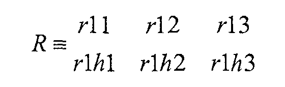

M - Neglecting M1P, M1M, M2P and M2M, the
filter 5 should distinguish as much as possible W from M0. Therefore, the maximum likelihood MSK Mark detector should decide W or M0 by measuring the Euclidean distance of the received signal R from W and from M0. The decision is based on the minimum distance. The decision is equivalent to the measurement of the correlation with the difference value M0-W, so the best filter MF should match to the difference of the two values:where tr stands for "time reversed". Considering the input stream of Table 1, this matched filter gives the following results as summarized in Table 2:
MW MW MW MSK MSK MSK MW MW MW MF out 4 4 4 4 0 -4 0 4 4 - The peak at -4 corresponds to the end of the MSK mark. It is apparent that the location of the MSK mark can be detected by searching the peak at -4.
The output of theabove filter 5 minimizes the probability of detecting W instead of M0 and vice versa. At the output of thefilter 5 the signal looks like the MSK mark in Figure 3. Where there is a MSK mark the signal is 0 -4 0, with a delay of a wobble period, otherwise it is equal to 4. - The
Sync detector 8 receives the output of theMSK filter 5 and manages two counters of thetime generator 7 by preloading them in the proper way.
Several solutions of different complexity can be envisaged for theSync detector 8. Fundamentally it is a state machine combined with an MSK mark detector. The MSK mark detector is a threshold detector, which detects an MSK mark when the signal is under the threshold -2. The inputs of the state machine are the addresses of the time generator counters and the detected MSK mark. The main states of the state machine are: - Reset: when an MSK mark is found it preloads 2 into the wobble counter and jumps to the ADIP unit lock state
- ADIP unit lock: when the next MSK comes, it analyses the
wobble counter address
- If the address is 12 or 14 or 2 it simply confirms the state
- If the address is 16 or 18 or 20 or 22 it properly preloads the ADIP unit counter
- Otherwise it preloads 2 into the wobble counter
- ADIP word lock: checks that MSK marks happen at the expected time.
- More complex solutions are possible to avoid false MSK mark detection, but they require a higher implementation cost in terms of silicon area.
- For the minimization of the error rate it is worth to use as much energy of the signal as possible for the detection of ADIP data bits. The detection can either use the location of the MSK mark or the phase of the second harmonic. The best detector uses both by properly mixing the sampled output of the
MSK filter 5 at thewobbles number HMW accumulator 6 at thelocation 54. The amplitude of the signals from theMSK filter 5 and theHMW accumulator 6 must be balanced, normalizing the effect of theMSK filter 5 and theHMW accumulator 6. For theMSK filter 5, the square sum of the coefficients gives a value of 8. For theHMW accumulator 6 the length of the integrator gives a value of 37. Therefore, the signals are divided byadder 10 combines the three paths in an optimised way. - Considering that the second I-path (1.5) and the third path (2) are not used at the same time, in an advantageous embodiment a reduction of implementation cost (in terms of silicon area) is achieved with a coherent demodulator as shown in Fig. 6. In this embodiment, the sin/cos generator, the multiplier and the integrate & dump are the same for the two paths. The time generator generates a proper signal to switch between two different functions: a unique generator can be used for the two functions if the input is multiplied by 1.5 or 2 and it is translated by π and the output is multiplied by 2 or 0.5. Of course this solution implies that ADIP word synchronization is available. So at the start-
up 2·cos1.5 is selected for the MSK mark search and then, after ADIP word synchronization, the switch is used.
Claims (9)
- Method for the demodulation of the ADIP data of a wobble signal of an optical recording medium, whereby the wobble signal is modulated using two different methods, comprising the steps ofrecovering the carrier of the wobble signal,demodulating the wobble signal based on the recovered carrier, andproviding a two-dimensional MSK filter for detecting MSK marks in the wobble signal.
- Method according to claim 1, characterized in that the step of demodulating the wobble signal based on the recovered carrier comprises down-converting the modulated data to the base band and demodulating the down-converted data.
- Method according to claims 1 or 2, characterized in it is applied to a wobble signal which is modulated using the methods of minimum shift keying (MSK) and harmonic modulated wave (HMW).
- Method according to claim 3, characterized in that a combination of MSK demodulation and HMW demodulation is used for demodulating the down-converted data, the combination being based on the locations of the MSK marks.
- Method according to one of claims 3 or 4, characterized in that the step of down-converting the modulated data to the base band comprises using three distinct correlation paths (31, 32, 33).
- Method according to claim 5, characterized in that the three distinct correlation paths (31, 32, 33) correlate to the in-phase carrier, the second harmonic of the carrier, and the 1.5 frequency of the carrier, respectively.
- Method according to claim 5 or 6, characterized in that at least two of the correlation paths (31, 32, 33) share components.
- Device for demodulating the ADIP data of a wobble signal of an optical recording medium, whereby the wobble signal is modulated using two different methods, characterized in that it performs a method according to one of claims 1 to 7.
- Apparatus for reading from and/or writing to recording media, characterized in that it uses a method according to anyone of claims 1 to 7 or comprises a device according to claim 8 for wobble demodulation.
Priority Applications (8)
| Application Number | Priority Date | Filing Date | Title |
|---|---|---|---|
| EP03013620A EP1489611A1 (en) | 2003-06-16 | 2003-06-16 | Wobble demodulation for high density optical recording media |
| EP04300148.6A EP1489612B1 (en) | 2003-06-16 | 2004-03-17 | Wobble demodulation for high density optical recording media |
| US10/853,679 US7529162B2 (en) | 2003-06-16 | 2004-05-25 | Wobble demodulation for high density optical recording media |
| TW093115209A TWI338292B (en) | 2003-06-16 | 2004-05-28 | Wobble demodulation for high density optical recording media |
| JP2004167235A JP4928716B2 (en) | 2003-06-16 | 2004-06-04 | Wobble demodulation method, device and apparatus for high density optical recording medium |
| MYPI20042288A MY143989A (en) | 2003-06-16 | 2004-06-15 | Wobble demodulation for high density optical recording media |
| KR1020040043834A KR101051451B1 (en) | 2003-06-16 | 2004-06-15 | Wobble Demodulation for High Density Optical Recording Media |
| CNB2004100495335A CN100468559C (en) | 2003-06-16 | 2004-06-16 | Demodulation of Wobble Signal in High Density Optical Recording Medium |
Applications Claiming Priority (1)
| Application Number | Priority Date | Filing Date | Title |
|---|---|---|---|
| EP03013620A EP1489611A1 (en) | 2003-06-16 | 2003-06-16 | Wobble demodulation for high density optical recording media |
Publications (1)
| Publication Number | Publication Date |
|---|---|
| EP1489611A1 true EP1489611A1 (en) | 2004-12-22 |
Family
ID=33395803
Family Applications (1)
| Application Number | Title | Priority Date | Filing Date |
|---|---|---|---|
| EP03013620A Withdrawn EP1489611A1 (en) | 2003-06-16 | 2003-06-16 | Wobble demodulation for high density optical recording media |
Country Status (7)
| Country | Link |
|---|---|
| US (1) | US7529162B2 (en) |
| EP (1) | EP1489611A1 (en) |
| JP (1) | JP4928716B2 (en) |
| KR (1) | KR101051451B1 (en) |
| CN (1) | CN100468559C (en) |
| MY (1) | MY143989A (en) |
| TW (1) | TWI338292B (en) |
Families Citing this family (10)
| Publication number | Priority date | Publication date | Assignee | Title |
|---|---|---|---|---|
| KR100574027B1 (en) * | 2004-12-17 | 2006-04-26 | 삼성전자주식회사 | Optical disc wobble information detection device and method |
| KR100615617B1 (en) | 2004-12-17 | 2006-08-25 | 삼성전자주식회사 | Optical disc wobble information detection device and method |
| TW200623045A (en) | 2004-12-21 | 2006-07-01 | Mediatek Inc | Device for accessing address information in optical disc |
| KR100636350B1 (en) | 2005-02-18 | 2006-10-19 | 엘지전자 주식회사 | Method for determining the position of the MS mark constituting the APD unit during reproduction of the wobble signal |
| CN100389460C (en) * | 2005-06-01 | 2008-05-21 | 上海乐金广电电子有限公司 | Jitter address error correction device for optical recording medium |
| KR100640658B1 (en) | 2005-07-29 | 2006-11-01 | 삼성전자주식회사 | Apparatus and method for detecting HMB signal using time variation in Blu-ray disc drive |
| TWI347596B (en) * | 2007-01-11 | 2011-08-21 | Ind Tech Res Inst | Optical recording carrier, signal generating apparatus, information recording method, and information reading apparatus |
| US8634283B1 (en) | 2011-08-08 | 2014-01-21 | Western Digital Technologies, Inc. | Disk drive performing in-drive spiral track writing |
| US8917474B1 (en) | 2011-08-08 | 2014-12-23 | Western Digital Technologies, Inc. | Disk drive calibrating a velocity profile prior to writing a spiral track |
| US8634154B1 (en) * | 2011-08-08 | 2014-01-21 | Western Digital Technologies, Inc. | Disk drive writing a sync mark seam in a bootstrap spiral track |
Citations (5)
| Publication number | Priority date | Publication date | Assignee | Title |
|---|---|---|---|---|
| WO2002073607A1 (en) * | 2001-03-12 | 2002-09-19 | Sony Corporation | Disc-shaped recording medium, disc-state recording medium cutting apparatus, and disc drive apparatus |
| WO2003005350A1 (en) * | 2001-07-02 | 2003-01-16 | Koninklijke Philips Electronics N.V. | Record carrier and apparatus for scanning the record carrier |
| WO2003034414A1 (en) * | 2001-10-16 | 2003-04-24 | Koninklijke Philips Electronics N.V. | Disc-shaped recording medium disc driving device and method and apparatus for producing disc |
| WO2003034413A1 (en) * | 2001-10-16 | 2003-04-24 | Koninklijke Philips Electronics N.V. | Disc driving device and wobble information detection method |
| US20030099180A1 (en) * | 2001-11-17 | 2003-05-29 | Park Jung Bae | Apparatus and method for encoding wobble signal to be recorded on optical disc, and apparatus and method for decoding wobble signal read from optical disc |
Family Cites Families (1)
| Publication number | Priority date | Publication date | Assignee | Title |
|---|---|---|---|---|
| KR100727916B1 (en) * | 2001-05-02 | 2007-06-13 | 삼성전자주식회사 | Optical disc |
-
2003
- 2003-06-16 EP EP03013620A patent/EP1489611A1/en not_active Withdrawn
-
2004
- 2004-05-25 US US10/853,679 patent/US7529162B2/en active Active
- 2004-05-28 TW TW093115209A patent/TWI338292B/en not_active IP Right Cessation
- 2004-06-04 JP JP2004167235A patent/JP4928716B2/en not_active Expired - Fee Related
- 2004-06-15 KR KR1020040043834A patent/KR101051451B1/en not_active Expired - Fee Related
- 2004-06-15 MY MYPI20042288A patent/MY143989A/en unknown
- 2004-06-16 CN CNB2004100495335A patent/CN100468559C/en not_active Expired - Lifetime
Patent Citations (6)
| Publication number | Priority date | Publication date | Assignee | Title |
|---|---|---|---|---|
| WO2002073607A1 (en) * | 2001-03-12 | 2002-09-19 | Sony Corporation | Disc-shaped recording medium, disc-state recording medium cutting apparatus, and disc drive apparatus |
| US20030165095A1 (en) * | 2001-03-12 | 2003-09-04 | Shinichiro Iimura | Disc-shaped recording medium, disc-state recording medium cutting apparatus, and disc drive apparatus |
| WO2003005350A1 (en) * | 2001-07-02 | 2003-01-16 | Koninklijke Philips Electronics N.V. | Record carrier and apparatus for scanning the record carrier |
| WO2003034414A1 (en) * | 2001-10-16 | 2003-04-24 | Koninklijke Philips Electronics N.V. | Disc-shaped recording medium disc driving device and method and apparatus for producing disc |
| WO2003034413A1 (en) * | 2001-10-16 | 2003-04-24 | Koninklijke Philips Electronics N.V. | Disc driving device and wobble information detection method |
| US20030099180A1 (en) * | 2001-11-17 | 2003-05-29 | Park Jung Bae | Apparatus and method for encoding wobble signal to be recorded on optical disc, and apparatus and method for decoding wobble signal read from optical disc |
Non-Patent Citations (1)
| Title |
|---|
| JUNG-BAE PARK ET AL: "A new address decoder using digital msk demodulation technique for the HD-DVD system", 2002 INTERNATIONAL SYMPOSIUM ON OPTICAL MEMORY AND OPTICAL DATA STORAGE, 7 July 2002 (2002-07-07) - 11 July 2002 (2002-07-11), pages 114 - 116, XP010600145 * |
Also Published As
| Publication number | Publication date |
|---|---|
| MY143989A (en) | 2011-07-29 |
| TWI338292B (en) | 2011-03-01 |
| CN1574046A (en) | 2005-02-02 |
| KR101051451B1 (en) | 2011-07-25 |
| JP4928716B2 (en) | 2012-05-09 |
| TW200504702A (en) | 2005-02-01 |
| CN100468559C (en) | 2009-03-11 |
| US7529162B2 (en) | 2009-05-05 |
| KR20040111044A (en) | 2004-12-31 |
| JP2005018968A (en) | 2005-01-20 |
| US20040252602A1 (en) | 2004-12-16 |
Similar Documents
| Publication | Publication Date | Title |
|---|---|---|
| Bernier et al. | Low complexity LoRa frame synchronization for ultra-low power software-defined radios | |
| US7433277B2 (en) | Wobble demodulator and wobble demodulation method | |
| US9906263B2 (en) | Method and system for information transmission | |
| USRE39513E1 (en) | Demodulation circuit for demodulating wobbling signal | |
| US7529162B2 (en) | Wobble demodulation for high density optical recording media | |
| EP1098302A2 (en) | Physical identification data addressing method using wobble signal, wobble address encoding circuit, method and circuit for detecting wobble address, and recording medium | |
| KR100301407B1 (en) | Manchester - Modulated FM signal modulator | |
| EP1320098A2 (en) | Apparatus and method for encoding wobble signal to be recorded on optical disc, and apparatus and method for decoding wobble signal read from optical disc | |
| EP1489612A1 (en) | Wobble demodulation for high density optical recording media | |
| TW200415619A (en) | Apparatus and method for recovering synchronization signals extracted from prerecorded information in optical storage devices | |
| CN100485791C (en) | Recording medium, wobble cycle detection method, wobble information detection method and circuit | |
| EP1511018A1 (en) | Wobble demodulation for high density optical recording media | |
| Patel et al. | Faster methods for GPS signal acquisition in frequency domain | |
| Whaits et al. | Phase errors in the coherent demodulation of VPSK and a solution using DSSS modulation | |
| WO2004061833A1 (en) | Recording medium, wobble cycle detection method, wobble information detection method, wobble information detection circuit, and information recording/reproduction device | |
| EP1585131A1 (en) | Circuit for wobble demodulation | |
| JPH07283762A (en) | Spread spectrum communication device | |
| JP2000040309A (en) | Clock reproduction device and address reproduction device | |
| JP2650556B2 (en) | Synchronous spread spectrum modulation demodulator | |
| JP3578575B2 (en) | Two-phase phase modulation transceiver | |
| EP1511019A1 (en) | Wobble demodulation for high density optical recording media | |
| Ko et al. | Wobble addressing method for land and groove structured optical storage | |
| JPH0795255A (en) | Psk demodulator | |
| Jeon et al. | QPSK wobble addressing method for rewritable land/groove optical disks | |
| Whaits | Investigation into variable shift keying using direct sequence spread spectrum techniques |
Legal Events
| Date | Code | Title | Description |
|---|---|---|---|
| PUAI | Public reference made under article 153(3) epc to a published international application that has entered the european phase |
Free format text: ORIGINAL CODE: 0009012 |
|
| AK | Designated contracting states |
Kind code of ref document: A1 Designated state(s): AT BE BG CH CY CZ DE DK EE ES FI FR GB GR HU IE IT LI LU MC NL PT RO SE SI SK TR |
|
| AX | Request for extension of the european patent |
Extension state: AL LT LV MK |
|
| AKX | Designation fees paid | ||
| REG | Reference to a national code |
Ref country code: DE Ref legal event code: 8566 |
|
| STAA | Information on the status of an ep patent application or granted ep patent |
Free format text: STATUS: THE APPLICATION IS DEEMED TO BE WITHDRAWN |
|
| 18D | Application deemed to be withdrawn |
Effective date: 20050623 |