EP1489478A2 - Method and apparatus for humidity control within a housing - Google Patents
Method and apparatus for humidity control within a housing Download PDFInfo
- Publication number
- EP1489478A2 EP1489478A2 EP04253615A EP04253615A EP1489478A2 EP 1489478 A2 EP1489478 A2 EP 1489478A2 EP 04253615 A EP04253615 A EP 04253615A EP 04253615 A EP04253615 A EP 04253615A EP 1489478 A2 EP1489478 A2 EP 1489478A2
- Authority
- EP
- European Patent Office
- Prior art keywords
- chamber
- humidity
- housing
- excess
- control circuitry
- Prior art date
- Legal status (The legal status is an assumption and is not a legal conclusion. Google has not performed a legal analysis and makes no representation as to the accuracy of the status listed.)
- Granted
Links
Images

Classifications
-
- G—PHYSICS
- G05—CONTROLLING; REGULATING
- G05D—SYSTEMS FOR CONTROLLING OR REGULATING NON-ELECTRIC VARIABLES
- G05D22/00—Control of humidity
- G05D22/02—Control of humidity characterised by the use of electric means
Definitions
- This invention relates in general to humidity control and, more particularly, to humidity control within a housing.
- Phased array antenna systems often involve the use of RF MMIC devices.
- an antenna array which is often referred to in the art as an active electronically scanned array (AESA)
- the spacing between antenna elements is determined by the operational frequency of the system. Consequently, as the operational frequency increases, the inter-element spacing between adjacent antenna elements decreases, which in turn decreases the size of the array and the amount of space available for the circuitry associated with each antenna element.
- the array In a traditional low-frequency antenna array, the array is relatively large, and there is a fair amount of space available in association with each antenna element. Due in part to the amount of available space, each MMIC is typically disposed within its own separate hermetic package. However, as the operating frequency increases, the use of a separate hermetic package for separate components becomes difficult or impossible.
- AESA active electronically scanned array
- the spacing between adjacent antenna elements will typically be about one-half of a wavelength, or in other words only about 0.175 inch.
- Permeation refers to the passage of a molecule through a solid barrier, and is different from leakage. In particular, permeation occurs when gas molecules dissolve into one side of a material such as a housing wall, diffuse through that material, and then evaporate from the far side of the material. In an AESA having a housing which includes a radome, the radome is often made from a material which is more susceptible to moisture permeation that other portions of the housing.
- an apparatus includes a housing which has a chamber, a replaceable part which has a moisture adsorption characteristic and which is in communication with the chamber, and a humidity monitoring section which is responsive to the humidity within the chamber.
- a method of controlling humidity within a chamber in a housing includes: providing a replaceable part which has a moisture adsorption characteristic and which is in communication with the chamber, and monitoring the humidity within the chamber using a humidity monitoring section which is responsive to the humidity within the chamber.
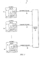
- FIGURE 1 is a block diagram of a system 10 which embodies aspects of the present invention.
- the system 10 includes a plurality of assemblies, three of which are shown at 12-14.
- the assemblies 12-14 each have a housing with a chamber therein, and each chamber contains a respective electronic circuit 16-18.
- the electronic circuit 16 includes the electrical function of a phased array antenna of a known type, which operates in the Ka frequency band at a frequency of approximately 35 GHz, and which thus has its adjacent antenna elements spaced by only about 0.175 inch.
- the electronic circuits 17-18 may also include the electrical function of a phased array antenna, or may be some other type of electronic circuit.
- Electronic circuits 16-18 each include a respective electronic humidity sensor 21-23, which can sense the relative humidity within the associated chamber.
- One suitable humidity sensor is available commercially as part number SHT11 from Sensirion AG of Switzerland. This particular humidity sensor can determine and report the actual humidity level, as opposed to just determining and reporting whether or not the humidity level is above a predetermined threshold.
- any other suitable electronic humidity sensor including a sensor of the type which simply indicates whether or not the ambient humidity is above a threshold, but cannot indicate the actual humidity level.
- Each of the assemblies 12-14 has therein a respective desiccant 26-28, which adsorbs moisture within the chamber in that assembly.
- Each desiccant 26-28 will adsorb moisture over time, until it has expended its moisture-adsorbing ability and needs to be replaced. Accordingly, the desiccants 26-28 can each be replaced, in a manner described in more detail later.
- the circuits 16-18 are each coupled to a central control circuit 31 by a respective communication link 36-38.
- Each communication link 36-38 can involve one or more different types of links that each support communication, such as cables, wireless links, and so forth.
- the control circuit 31 may be in a physical location which is very remote from one or more of the assemblies 12-14.
- the assembly 12 could be provided on some type of mobile military vehicle such as a tank, and the control circuit 31 could be disposed in a command headquarters which is located many miles from the tank. In that situation, at least a portion of the communication link 36 between the tank and headquarters would be implemented with a wireless link which involves the transmission of radio-frequency signals, either directly or through a satellite.
- the humidity sensors 21-23 each monitor the humidity level within the chamber of a respective assembly 12-14.
- the desiccants 26-28 each adsorb moisture in order to keep the humidity levels relatively low within each chamber, until the time when the desiccant has adsorbed so much moisture that it cannot continue to efficiently adsorb more moisture, and therefore experiences a progressive reduction in its capability to adsorb further moisture.
- the humidity in the associated chamber will begin to rise.
- the control circuit 31 can monitor the humidity within each chamber, and determine whether the humidity in any chamber has exceeded a predetermined threshold level.
- control circuit 31 When the humidity in any given chamber exceeds the threshold, it will typically be because the desiccant in that chamber needs to be replaced. In that event, the control circuit 31 will provide a service crew with a list of the specific assemblies in which the desiccant needs to be replaced, and the current locations of those assemblies.
- control circuit 31 also evaluates the extent to which the humidity in each chamber is in excess of the specified threshold, and prioritizes assemblies in the list given to the service crew, so that the assemblies appear in an order running from those with the largest degree of excess humidity to those with the smallest degree of excess humidity.
- This prioritization can also take one or more other factors into account, such as the current operational context of a given assembly. For example, if an assembly with a lower degree of excess humidity is currently in a combat situation, it could be assigned a higher level of priority than another assembly which has a higher degree of excess humidity but is not currently in a combat situation.
- the service crew would service the assemblies in approximately the same order in which they appear on the list, so that assemblies assigned the highest priority would be serviced first.
- the control circuit 31 could output a list of all assemblies in which the detected humidity is in excess of a predetermined threshold. This list could be produced with no prioritization of the assemblies in the list, or with a prioritization based on one or more criteria other than humidity, such as the current operational context of each assembly.
- FIGURE 2 is a diagrammatic fragmentary perspective view which shows in greater detail the assembly 12 of FIGURE 1, and which also shows the control circuit 31 and communication link 36 of FIGURE 1.
- the assembly 12 has a housing with a chamber therein.
- the housing is defined by a bottom part 101, a central part 102, and a top part 103.
- the central part 102 has a rectangular opening which extends vertically through it, and which effectively serves as the chamber in that assembly.
- the bottom part 101 is fixedly secured to the central part 102 by a plurality of bolts 106
- the top part 103 is fixedly secured to the central part 102 by a plurality of bolts 107.
- a not-illustrated O-ring is provided between the parts 101 and 102, and another not-illustrated O-ring is provided between the parts 102 and 103, in order to resist the entry of moisture into the housing.
- the top part 103 includes a frame 111, and a radome 112 which is fixedly and sealingly mounted within the frame 111.
- the circuit 16 within the assembly 12 includes a phased array antenna of a known type. The antenna elements transmit and/or receive radiation through the radome 112, in a manner which is known in the art.
- each connector would include some form of moisture seal, such as an appropriate O-ring.
- the communication link 36 is coupled to the connector 123, in order to operationally couple the control circuit 31 to the circuit disposed within the assembly 12.
- the central part 102 has, on one side thereof, a projection 141 of approximately semi-cylindrical shape, which extends the full length of the central part 102.
- a cylindrical opening 142 opens into the projection 141 from one end thereof, and extends most of the length of the projection 141.
- the central part 102 of the housing has a wall portion 146, which is disposed between the opening 142 and the chamber within the assembly 12.
- the wall portion 146 has a plurality of openings 147 through it, which provide communication between the opening 142 and the chamber.
- the outer surface of the projection 141 has a groove which concentrically encircles the open end of the opening 142, and an O-ring 151 is seated within the groove.
- the assembly 12 also includes a replaceable cartridge 171.
- the cartridge 171 has a cylindrical portion, which is the desiccant 26.
- the desiccant 26 is a molecular sieve desiccant of a known type.
- the desiccant 26 has a uniform network of synthetic zeolite crystalline pores and cavities. This desiccant will not give up previously-adsorbed moisture as readily as other desiccants (such as a silica gel), and has a higher adsorption equilibrium capacity for water vapor under low humidity conditions than other desiccants (such as a silica gel).
- the pore size in the desiccant 26 of the disclosed embodiment is about 4 Angstroms.
- the desiccant 26 could be implemented with some other suitable moisture-adsorbing material, such a silica gel.
- the size and composition of the desiccant 26 have been selected so that, under normal conditions, the desiccant 26 should keep the humidity within the assembly 12 below a selected threshold for at least a year.
- the cartridge 171 has an end portion which includes a threaded cylindrical portion 181 and a hexagonal flange 182.
- the cylindrical portion 181 is provided between and is fixedly coupled to each of the desiccant 26 and the flange 182.
- a unidirectional check valve 186 is installed in the center of the end portion of the cartridge 171, and communicates with the desiccant 26. The valve 186 will permit a pressurized gas to flow into the assembly 12 through the desiccant 26, but resists any gas flow in the opposite direction.
- a unidirectional relief valve 187 is installed in a wall of the central part 102. In response to excess gas pressure within the chamber in the assembly 12, the relief valve 187 permits gas to flow out of the chamber through the valve 187 to the exterior of the assembly 12. However, the valve 187 resists any gas flow in the opposite direction.
- the relief valve 187 in the disclosed embodiment is a unidirectional valve, it could alternatively be a bidirectional valve.
- the cartridge 171 is shown in a partly withdrawn state, for the purpose of clarity.
- the desiccant 26 of the cartridge 171 would be disposed completely within the opening 142 in the projection 141, and the threaded cylindrical portion 181 would be engaged with the not-illustrated internal threads at the end of the opening 142.
- the hexagonal flange 182 would have one side surface firmly and sealingly engaging the O-ring 151, in order to provide a seal which resists the entry of moisture into the opening 141 from externally of the assembly 12.
- the cartridge 171 in the disclosed embodiment is held in place by cooperation of the external threads on the cylindrical portion 181 and the not-illustrated internal threads at the end of the opening 142, it would alternatively be possible to omit both sets of threads and to secure the cartridge in place in some other manner.
- the flange 182 could have several circumferentially spaced holes extending through it
- the projection 141 could have several threaded holes provided at circumferentially spaced locations around the open end of the opening 142
- several bolts could each extend through a respective hole in the flange 182 and threadedly engage a respective threaded hole in the projection 141.
- permeation is different from leakage, and refers to the passage of a molecule through a solid barrier.
- permeation occurs when gas molecules dissolve into one side of a material such as a housing wall, diffuse through that material, and then evaporate from the far side of the material.
- the desiccant 26 can adsorb small amounts of moisture which manage to enter the chamber due to leakage or permeation. After at least a year of normal operation, however, the desiccant 26 will reach a point where it has adsorbed so much moisture that it cannot continue to efficiently adsorb additional moisture, and therefore experiences a reduction in its ability to adsorb further moisture. As a result, the humidity level within the assembly 12 will begin to slowly and progressively increase, and this rising humidity level will be detected by the humidity sensor 21 and relayed to the control circuit 31.
- the detection of the humidity level by the humidity sensor may be carried out by periodically executing some form of built-in test (BIT) routine that interrogates the sensor.
- BIT built-in test
- This test routine may be carried out independently within each assembly at the assembly level, or may be part of a system-level test that includes a number of assemblies and also the control circuit.
- this information is relayed to the control circuit 31, along with a unique identification code assigned to that particular assembly.
- each humidity sensor determines the actual humidity level, and this information is sent to the control circuit 31.
- the control circuit would simply be notified that the humidity had exceeded the threshold.
- the control circuit 31 will then notify a service crew that the cartridge 171 in a specified assembly needs to be replaced.
- the control circuit 31 can prioritize the assemblies in the list, based on one or more criteria. For example, if the control circuit 31 has been provided with information indicating the actual humidity level in each assembly, the control circuit can determine the extent to which the actual humidity level exceeds a threshold in each assembly, and higher degree of priority can be given to assemblies in which this difference is larger.
- Another criteria which can be used for prioritization is the current operational context of each assembly needing service. For example, in a military context, if some of the assemblies are currently in a combat situation and others are not, a higher degree of priority can be given to the assemblies involved in the combat situation.
- the service crew will then select from the list an assembly which has a relatively high priority, and will go to that assembly with a service kit containing a replacement cartridge 171 and also a charge bottle 191 filled with pressurized dry nitrogen.
- the service crew will use a wrench to rotate the hexagonal flange 182 on the previously-installed cartridge 171, in order to disengage the threads 181 from the internal threads of the opening 142.
- the original cartridge 171 is then extracted from the assembly, and either discarded or saved for recycling.
- the replacement cartridge 171 is inserted into the opening 141, and is rotated so as to engage its threads 181 with the internal threads of the opening 142.
- the wrench is then engaged with the hexagonal flange 182, and is used to rotate the replacement cartridge 171 until a surface on one side of the flange 182 is firmly and sealingly engaging the O-ring 151, in order to provide a moisture-resistant seal.
- the service crew couples to the valve 186 a fitting on the dry nitrogen charge bottle 191.
- a valve within the fitting is physically opened, and permits the pressurized nitrogen within the bottle 191 to reach the valve 186.
- the pressure of the dry nitrogen opens the valve 186, and causes a quantity of the dry nitrogen gas from the bottle 191 to flow through the valve 186, the desiccant 26, the opening 141, and the openings 147, and into the chamber within the assembly 12.
- moisture-laden air which may have entered the opening 141 during the cartridge replacement procedure is forced through the openings 147 and into the chamber, and is then forced out of the chamber through the relief valve 187.
- valve 186 When the pressure within the bottle 191 decreases to a point where it is no longer sufficient to keep the valve 186 open, the valve 186 will automatically close. By this point in time, the opening 142 and the chamber in the assembly 12 will both have been substantially filled with dry nitrogen gas from the bottle 191, with little residual air or water vapor.
- the present invention provides a number of advantages.
- One such advantage results from the provision of a low permeability housing containing a desiccant to adsorb moisture, along with electronic sensing and monitoring of humidity within the housing.
- This approach provides a non-hermetic solution to humidity control, which can provide a level of humidity control satisfactory for applications that would otherwise need a hermetic solution, and which is particularly advantageous in certain applications where a hermetic approach is difficult or impossible, such as a package for a very high frequency antenna array.
- By electronically monitoring humidity a central facility can efficiently monitor hundreds of similar devices, and can easily identify those in which humidity levels have become problematic. A service crew is dispatched to service specific devices in which the desiccant needs to be replaced.
- the desiccant is configured as a cartridge that can be replaced in the field.
- humidity control is effected at the assembly level, in contrast to the traditional approach of providing separate hermetic packages for each of a number of components within each assembly. This is particularly advantageous in systems such as those with high-frequency antenna arrays, where dense packaging requirements make it difficult to use traditional hermetic packages for each of a number of separate system components.
- Still another advantage results from the provision of the capability to carry out a dry nitrogen purge of an assembly after replacement of the desiccant, in order to substantially expel any free moisture which may have entered the enclosure with external air as the desiccant was replaced. This purge helps to maximize the efficiency and operational lifetime of the replacement desiccant.
Landscapes
- Physics & Mathematics (AREA)
- General Physics & Mathematics (AREA)
- Engineering & Computer Science (AREA)
- Automation & Control Theory (AREA)
- Drying Of Gases (AREA)
- Control Of Non-Electrical Variables (AREA)
Abstract
Description
Claims (20)
- An apparatus, comprising:a housing having a chamber therein;a replaceable part (171) which has a moisture adsorption characteristic and which is in communication with said chamber; anda humidity monitoring section which is responsive to the humidity within said chamber.
- An apparatus according to claim 1, wherein said humidity monitoring section includes a humidity sensor (21, 22, 23) disposed within said chamber, and control circuitry (31) coupled to said humidity sensor for determining the humidity within said chamber.
- An apparatus according to claim 2, wherein said control circuitry (31) determines whether the humidity within said chamber is in excess of a selected threshold.
- An apparatus according to claim 2 or claim 3,
including a plurality of further housings which each have therein a respective further chamber;
including a plurality of further replaceable parts (171) which each have a moisture adsorption characteristic and which are each in communication with a respective said further chamber;
wherein said humidity monitoring section includes a plurality of further humidity sensors (21, 22, 23) which are each disposed in a respective said further chamber; and
wherein said control circuitry (31) is coupled to each of said further humidity sensors (21, 22, 23) for determining the humidity within each of said further chambers. - An apparatus according to claim 4, wherein said control circuitry (31) determines whether the humidity within each of said chambers is in excess of a selected threshold, and provides an identification of those chambers in which the humidity is in excess of the selected threshold, prioritized by the degree of excess humidity in each such chamber.
- An apparatus according to any preceding claim,
wherein said housing has an opening (142) through which said replaceable part (171) can be inserted and removed; and
including sealing structure (182) which can selectively sealingly close said opening (142). - An apparatus according to claim 6, wherein said sealing structure (182) includes a portion of said replaceable part (171).
- An apparatus according to any preceding claim, wherein said replaceable part (171) includes a portion (26, 27, 28) which is one of a molecular sieve desiccant and a silica gel.
- An apparatus according to any preceding claim, wherein said housing includes structure (186) for facilitating introduction of a dry gas into said chamber.
- An apparatus according to claim 9, wherein said dry gas is dry nitrogen.
- An apparatus according to claim 9 or claim 10,
including a first valve (186) which is provided through said housing at a first location, which has a closed state that prevents a flow of gas between said chamber and a location external to said housing, and which has an open state that permits a flow of gas into said chamber;
including a second valve (187) which is provided through said housing at a second location spaced from first location, which has a closed state that prevents a flow of gas between said chamber and a location external to said housing, and which has an open state that permits a flow of gas out of said chamber; and
including a source of dry gas (191) which can be selectively coupled to said first valve (186). - An apparatus according to claim 11, wherein said source of dry gas (191) includes a container having therein a quantity of said dry gas which is pressurized, and includes a fitting which facilitates a releasable coupling of said container to said first valve (186).
- An apparatus according to any preceding claim,
wherein said housing includes a wall portion which is a radome (112) having on one side thereof a surface which is a portion of an exterior surface of said housing and having on the other side thereof a surface which bounds a portion of said chamber; and
including a phased array antenna system which is disposed within said chamber. - A method of controlling humidity within a chamber in a housing, comprising:providing a replaceable part (171) which has a moisture adsorption characteristic and which is in communication with said chamber; andmonitoring the humidity within said chamber using a humidity monitoring section (10) which is responsive to the humidity within said chamber.
- The method according to claim 14, wherein said humidity monitoring section includes a humidity sensor (21, 22, 23) within said chamber and control circuitry (31) coupled to said humidity sensor; and
wherein said monitoring includes determining the humidity within said chamber using said control circuitry and said humidity sensor. - The method according to claim 15, wherein said determining includes determining whether the humidity within said chamber is in excess of a selected threshold.
- The method according to claim 15,
including providing a plurality of further housings which each have therein a respective further chamber, a plurality of further humidity sensors (21, 22, 23) which are each coupled to said control circuitry (31) and are each disposed in a respective said further chamber, and a plurality of further replaceable parts (171) which each have a moisture adsorption characteristic and which are each in communication with a respective said further chamber; and
wherein said monitoring includes determining the humidity within each of said further chambers using said control circuitry (31) and said further humidity sensors (21, 22, 23). - The method according to claim 17, wherein said monitoring includes:determining whether the humidity within each of said chambers is in excess of a selected threshold; andproviding an identification of those chambers in which the humidity is in excess of the selected threshold, prioritized by the degree of excess humidity in each such chamber.
- A method according to any of claims 14 to 18, including:determining whether the humidity within said chamber, or a said chamber, is in excess of a predetermined threshold;responding to a determination that the humidity is in excess of said selected threshold by replacing said replaceable part (171); andthereafter introducing a quantity of a dry gas into said chamber, or a said chamber.
- A method according to claim 19, including selecting dry nitrogen for use as said dry gas.
Applications Claiming Priority (2)
| Application Number | Priority Date | Filing Date | Title |
|---|---|---|---|
| US10/465,115 US7195177B2 (en) | 2003-06-18 | 2003-06-18 | Method and apparatus for humidity control within a housing |
| US465115 | 2003-06-18 |
Publications (3)
| Publication Number | Publication Date |
|---|---|
| EP1489478A2 true EP1489478A2 (en) | 2004-12-22 |
| EP1489478A3 EP1489478A3 (en) | 2005-11-23 |
| EP1489478B1 EP1489478B1 (en) | 2015-04-22 |
Family
ID=33418183
Family Applications (1)
| Application Number | Title | Priority Date | Filing Date |
|---|---|---|---|
| EP20040253615 Expired - Lifetime EP1489478B1 (en) | 2003-06-18 | 2004-06-17 | Method and apparatus for humidity control within a housing |
Country Status (2)
| Country | Link |
|---|---|
| US (1) | US7195177B2 (en) |
| EP (1) | EP1489478B1 (en) |
Cited By (1)
| Publication number | Priority date | Publication date | Assignee | Title |
|---|---|---|---|---|
| EP3279437A1 (en) * | 2016-08-03 | 2018-02-07 | United Technologies Corporation | Localized engine protection from corrosion and contamination |
Families Citing this family (10)
| Publication number | Priority date | Publication date | Assignee | Title |
|---|---|---|---|---|
| US7454920B2 (en) * | 2004-11-04 | 2008-11-25 | Raytheon Company | Method and apparatus for moisture control within a phased array |
| DE102009016848B4 (en) * | 2009-04-08 | 2011-12-01 | Siemens Aktiengesellschaft | Gas analyzer with a combination of gas dehumidifier and gas converter |
| US20110212677A1 (en) * | 2010-02-26 | 2011-09-01 | Pratt & Whitney Canada Corp. | Housing assembly for an electrical device |
| US20140026600A1 (en) * | 2012-07-25 | 2014-01-30 | Erik A. Wippler | Hvac system of an automotive vehicle and method of operating the same |
| US9506887B2 (en) | 2014-12-08 | 2016-11-29 | Symbol Technologies, Llc | Field replaceable desiccant cartridge and device, method and system therefor |
| JP6499532B2 (en) * | 2015-06-30 | 2019-04-10 | ファナック株式会社 | A rotary encoder with a function to obtain the moisture absorption amount of the moisture absorbent |
| US10876446B2 (en) | 2018-05-14 | 2020-12-29 | Des-Case Corporation | System and apparatus for a diagnostic breather dryer having a coupleable expansion pack |
| US10621851B1 (en) | 2018-06-18 | 2020-04-14 | Waymo Llc | Humidity control system |
| US11102588B2 (en) * | 2019-08-06 | 2021-08-24 | Daniel R. Schumaier | Hearing aid dryer and disinfection kit |
| US11266757B2 (en) | 2019-08-06 | 2022-03-08 | Daniel R. Schumaier | Hearing aid dryer and disinfection kit with UV-reflective drying tray |
Family Cites Families (7)
| Publication number | Priority date | Publication date | Assignee | Title |
|---|---|---|---|---|
| AT260577B (en) | 1965-09-17 | 1968-03-11 | Voest Ag | Device for determining the moisture content of adsorptive air drying devices, in particular gel dryers |
| US3796615A (en) * | 1971-06-23 | 1974-03-12 | Hayes Inc C I | Method of vacuum carburizing |
| US4642715A (en) * | 1984-11-01 | 1987-02-10 | Miltope Corporation | Environmental conditioning and safety system for disk-type mass memories |
| US4755031A (en) * | 1987-07-20 | 1988-07-05 | Daviau Christopher A | Optical apparatus dehydrator |
| JPH03165812A (en) | 1989-11-27 | 1991-07-17 | Matsushita Electric Works Ltd | Dehumidifier |
| US5257008A (en) * | 1991-09-26 | 1993-10-26 | Allied-Signal Inc. | Compressed air system with warning mechanism for air dryer service life indication |
| US6654573B2 (en) * | 2002-02-21 | 2003-11-25 | Hewlett-Packard Development Company, Lp. | Paper tray moisture control |
-
2003
- 2003-06-18 US US10/465,115 patent/US7195177B2/en not_active Expired - Lifetime
-
2004
- 2004-06-17 EP EP20040253615 patent/EP1489478B1/en not_active Expired - Lifetime
Cited By (3)
| Publication number | Priority date | Publication date | Assignee | Title |
|---|---|---|---|---|
| EP3279437A1 (en) * | 2016-08-03 | 2018-02-07 | United Technologies Corporation | Localized engine protection from corrosion and contamination |
| US20180038242A1 (en) * | 2016-08-03 | 2018-02-08 | United Technologies Corporation | Localized engine protection from corrosion and contamination |
| US10450891B2 (en) * | 2016-08-03 | 2019-10-22 | United Technologies Corporation | Localized engine protection from corrosion and contamination |
Also Published As
| Publication number | Publication date |
|---|---|
| EP1489478A3 (en) | 2005-11-23 |
| US7195177B2 (en) | 2007-03-27 |
| US20040255598A1 (en) | 2004-12-23 |
| EP1489478B1 (en) | 2015-04-22 |
Similar Documents
| Publication | Publication Date | Title |
|---|---|---|
| EP1489478B1 (en) | Method and apparatus for humidity control within a housing | |
| EP2036413B1 (en) | Housing and method for keeping dry an electronic circuit | |
| US7332015B2 (en) | Automatic dehydrating breather apparatus and method | |
| US8657939B2 (en) | Air dryer cartridge for a compressed air treatment system of a vehicle | |
| US6878194B2 (en) | Remote purge drying unit for compressed gas | |
| US4594082A (en) | Dehydrating air-filtering apparatus | |
| US6797037B2 (en) | Dehydrating breather apparatus and method | |
| US7847189B2 (en) | Electrical Component | |
| US5665146A (en) | Dehumidifier | |
| US7160368B1 (en) | System and method for gettering gas-phase contaminants within a sealed enclosure | |
| CN107046784A (en) | Electronic and electrical equipment storing apparatus and electronic and electrical equipment | |
| EP1659842B1 (en) | Method and apparatus for moisture control within a phased array | |
| US6254258B1 (en) | Sealed light fixture | |
| US7691163B2 (en) | Vehicle air dryer | |
| US7249867B2 (en) | Sealed lighting fixture having mechanisms for venting and equalizing interior air pressure | |
| EP3243677A1 (en) | Oil refill container | |
| CN210440967U (en) | Adsorbent device and storage and transportation tank | |
| US6273941B1 (en) | Desiccant package having a controllable permeation rate for high reliability applications | |
| US20060033673A1 (en) | Integral sealed antenna mount for cellular based monitors | |
| CN114641604B (en) | Diagnostic Breather Dryer | |
| KR940000928Y1 (en) | Drying apparatus by the compressed air | |
| KR101774251B1 (en) | Humidity removal structure of electronic control unit and electronic control unit having the same | |
| KR102960404B1 (en) | Respirator for transformer | |
| CN220960155U (en) | Septic tank monitoring intelligent terminal all-in-one | |
| JP2025148255A (en) | Apparatus having an oil protection assembly, an oil protection vent valve, and an oil tank |
Legal Events
| Date | Code | Title | Description |
|---|---|---|---|
| PUAI | Public reference made under article 153(3) epc to a published international application that has entered the european phase |
Free format text: ORIGINAL CODE: 0009012 |
|
| AK | Designated contracting states |
Kind code of ref document: A2 Designated state(s): AT BE BG CH CY CZ DE DK EE ES FI FR GB GR HU IE IT LI LU MC NL PL PT RO SE SI SK TR |
|
| AX | Request for extension of the european patent |
Extension state: AL HR LT LV MK |
|
| PUAL | Search report despatched |
Free format text: ORIGINAL CODE: 0009013 |
|
| AK | Designated contracting states |
Kind code of ref document: A3 Designated state(s): AT BE BG CH CY CZ DE DK EE ES FI FR GB GR HU IE IT LI LU MC NL PL PT RO SE SI SK TR |
|
| AX | Request for extension of the european patent |
Extension state: AL HR LT LV MK |
|
| 17P | Request for examination filed |
Effective date: 20060329 |
|
| AKX | Designation fees paid |
Designated state(s): AT BE BG CH CY CZ DE DK EE ES FI FR GB GR HU IE IT LI LU MC NL PL PT RO SE SI SK TR |
|
| GRAP | Despatch of communication of intention to grant a patent |
Free format text: ORIGINAL CODE: EPIDOSNIGR1 |
|
| INTG | Intention to grant announced |
Effective date: 20141110 |
|
| GRAS | Grant fee paid |
Free format text: ORIGINAL CODE: EPIDOSNIGR3 |
|
| GRAA | (expected) grant |
Free format text: ORIGINAL CODE: 0009210 |
|
| AK | Designated contracting states |
Kind code of ref document: B1 Designated state(s): AT BE BG CH CY CZ DE DK EE ES FI FR GB GR HU IE IT LI LU MC NL PL PT RO SE SI SK TR |
|
| REG | Reference to a national code |
Ref country code: GB Ref legal event code: FG4D |
|
| REG | Reference to a national code |
Ref country code: CH Ref legal event code: EP |
|
| REG | Reference to a national code |
Ref country code: AT Ref legal event code: REF Ref document number: 723584 Country of ref document: AT Kind code of ref document: T Effective date: 20150515 |
|
| REG | Reference to a national code |
Ref country code: IE Ref legal event code: FG4D |
|
| REG | Reference to a national code |
Ref country code: DE Ref legal event code: R096 Ref document number: 602004047043 Country of ref document: DE Effective date: 20150603 |
|
| REG | Reference to a national code |
Ref country code: NL Ref legal event code: VDEP Effective date: 20150422 |
|
| REG | Reference to a national code |
Ref country code: AT Ref legal event code: MK05 Ref document number: 723584 Country of ref document: AT Kind code of ref document: T Effective date: 20150422 |
|
| PG25 | Lapsed in a contracting state [announced via postgrant information from national office to epo] |
Ref country code: NL Free format text: LAPSE BECAUSE OF FAILURE TO SUBMIT A TRANSLATION OF THE DESCRIPTION OR TO PAY THE FEE WITHIN THE PRESCRIBED TIME-LIMIT Effective date: 20150422 |
|
| PG25 | Lapsed in a contracting state [announced via postgrant information from national office to epo] |
Ref country code: FI Free format text: LAPSE BECAUSE OF FAILURE TO SUBMIT A TRANSLATION OF THE DESCRIPTION OR TO PAY THE FEE WITHIN THE PRESCRIBED TIME-LIMIT Effective date: 20150422 Ref country code: PT Free format text: LAPSE BECAUSE OF FAILURE TO SUBMIT A TRANSLATION OF THE DESCRIPTION OR TO PAY THE FEE WITHIN THE PRESCRIBED TIME-LIMIT Effective date: 20150824 Ref country code: ES Free format text: LAPSE BECAUSE OF FAILURE TO SUBMIT A TRANSLATION OF THE DESCRIPTION OR TO PAY THE FEE WITHIN THE PRESCRIBED TIME-LIMIT Effective date: 20150422 |
|
| PG25 | Lapsed in a contracting state [announced via postgrant information from national office to epo] |
Ref country code: GR Free format text: LAPSE BECAUSE OF FAILURE TO SUBMIT A TRANSLATION OF THE DESCRIPTION OR TO PAY THE FEE WITHIN THE PRESCRIBED TIME-LIMIT Effective date: 20150723 Ref country code: AT Free format text: LAPSE BECAUSE OF FAILURE TO SUBMIT A TRANSLATION OF THE DESCRIPTION OR TO PAY THE FEE WITHIN THE PRESCRIBED TIME-LIMIT Effective date: 20150422 |
|
| REG | Reference to a national code |
Ref country code: DE Ref legal event code: R097 Ref document number: 602004047043 Country of ref document: DE |
|
| PG25 | Lapsed in a contracting state [announced via postgrant information from national office to epo] |
Ref country code: EE Free format text: LAPSE BECAUSE OF FAILURE TO SUBMIT A TRANSLATION OF THE DESCRIPTION OR TO PAY THE FEE WITHIN THE PRESCRIBED TIME-LIMIT Effective date: 20150422 Ref country code: DK Free format text: LAPSE BECAUSE OF FAILURE TO SUBMIT A TRANSLATION OF THE DESCRIPTION OR TO PAY THE FEE WITHIN THE PRESCRIBED TIME-LIMIT Effective date: 20150422 Ref country code: MC Free format text: LAPSE BECAUSE OF FAILURE TO SUBMIT A TRANSLATION OF THE DESCRIPTION OR TO PAY THE FEE WITHIN THE PRESCRIBED TIME-LIMIT Effective date: 20150422 Ref country code: IT Free format text: LAPSE BECAUSE OF FAILURE TO SUBMIT A TRANSLATION OF THE DESCRIPTION OR TO PAY THE FEE WITHIN THE PRESCRIBED TIME-LIMIT Effective date: 20150422 |
|
| REG | Reference to a national code |
Ref country code: CH Ref legal event code: PL |
|
| PLBE | No opposition filed within time limit |
Free format text: ORIGINAL CODE: 0009261 |
|
| STAA | Information on the status of an ep patent application or granted ep patent |
Free format text: STATUS: NO OPPOSITION FILED WITHIN TIME LIMIT |
|
| PG25 | Lapsed in a contracting state [announced via postgrant information from national office to epo] |
Ref country code: SK Free format text: LAPSE BECAUSE OF FAILURE TO SUBMIT A TRANSLATION OF THE DESCRIPTION OR TO PAY THE FEE WITHIN THE PRESCRIBED TIME-LIMIT Effective date: 20150422 Ref country code: CZ Free format text: LAPSE BECAUSE OF FAILURE TO SUBMIT A TRANSLATION OF THE DESCRIPTION OR TO PAY THE FEE WITHIN THE PRESCRIBED TIME-LIMIT Effective date: 20150422 Ref country code: LU Free format text: LAPSE BECAUSE OF FAILURE TO SUBMIT A TRANSLATION OF THE DESCRIPTION OR TO PAY THE FEE WITHIN THE PRESCRIBED TIME-LIMIT Effective date: 20150617 Ref country code: RO Free format text: LAPSE BECAUSE OF NON-PAYMENT OF DUE FEES Effective date: 20150422 Ref country code: PL Free format text: LAPSE BECAUSE OF FAILURE TO SUBMIT A TRANSLATION OF THE DESCRIPTION OR TO PAY THE FEE WITHIN THE PRESCRIBED TIME-LIMIT Effective date: 20150422 |
|
| REG | Reference to a national code |
Ref country code: IE Ref legal event code: MM4A |
|
| 26N | No opposition filed |
Effective date: 20160125 |
|
| PG25 | Lapsed in a contracting state [announced via postgrant information from national office to epo] |
Ref country code: IE Free format text: LAPSE BECAUSE OF NON-PAYMENT OF DUE FEES Effective date: 20150617 Ref country code: CH Free format text: LAPSE BECAUSE OF NON-PAYMENT OF DUE FEES Effective date: 20150630 Ref country code: LI Free format text: LAPSE BECAUSE OF NON-PAYMENT OF DUE FEES Effective date: 20150630 |
|
| REG | Reference to a national code |
Ref country code: FR Ref legal event code: PLFP Year of fee payment: 13 |
|
| PG25 | Lapsed in a contracting state [announced via postgrant information from national office to epo] |
Ref country code: SI Free format text: LAPSE BECAUSE OF FAILURE TO SUBMIT A TRANSLATION OF THE DESCRIPTION OR TO PAY THE FEE WITHIN THE PRESCRIBED TIME-LIMIT Effective date: 20150422 |
|
| PG25 | Lapsed in a contracting state [announced via postgrant information from national office to epo] |
Ref country code: BE Free format text: LAPSE BECAUSE OF FAILURE TO SUBMIT A TRANSLATION OF THE DESCRIPTION OR TO PAY THE FEE WITHIN THE PRESCRIBED TIME-LIMIT Effective date: 20150422 |
|
| REG | Reference to a national code |
Ref country code: FR Ref legal event code: PLFP Year of fee payment: 14 |
|
| PG25 | Lapsed in a contracting state [announced via postgrant information from national office to epo] |
Ref country code: HU Free format text: LAPSE BECAUSE OF FAILURE TO SUBMIT A TRANSLATION OF THE DESCRIPTION OR TO PAY THE FEE WITHIN THE PRESCRIBED TIME-LIMIT; INVALID AB INITIO Effective date: 20040617 Ref country code: BG Free format text: LAPSE BECAUSE OF FAILURE TO SUBMIT A TRANSLATION OF THE DESCRIPTION OR TO PAY THE FEE WITHIN THE PRESCRIBED TIME-LIMIT Effective date: 20150422 |
|
| PG25 | Lapsed in a contracting state [announced via postgrant information from national office to epo] |
Ref country code: CY Free format text: LAPSE BECAUSE OF FAILURE TO SUBMIT A TRANSLATION OF THE DESCRIPTION OR TO PAY THE FEE WITHIN THE PRESCRIBED TIME-LIMIT Effective date: 20150422 Ref country code: SE Free format text: LAPSE BECAUSE OF FAILURE TO SUBMIT A TRANSLATION OF THE DESCRIPTION OR TO PAY THE FEE WITHIN THE PRESCRIBED TIME-LIMIT Effective date: 20150422 |
|
| PG25 | Lapsed in a contracting state [announced via postgrant information from national office to epo] |
Ref country code: TR Free format text: LAPSE BECAUSE OF FAILURE TO SUBMIT A TRANSLATION OF THE DESCRIPTION OR TO PAY THE FEE WITHIN THE PRESCRIBED TIME-LIMIT Effective date: 20150422 |
|
| REG | Reference to a national code |
Ref country code: FR Ref legal event code: PLFP Year of fee payment: 15 |
|
| PGFP | Annual fee paid to national office [announced via postgrant information from national office to epo] |
Ref country code: FR Payment date: 20230523 Year of fee payment: 20 Ref country code: DE Payment date: 20230523 Year of fee payment: 20 |
|
| P01 | Opt-out of the competence of the unified patent court (upc) registered |
Effective date: 20230630 |
|
| PGFP | Annual fee paid to national office [announced via postgrant information from national office to epo] |
Ref country code: GB Payment date: 20230523 Year of fee payment: 20 |
|
| REG | Reference to a national code |
Ref country code: DE Ref legal event code: R071 Ref document number: 602004047043 Country of ref document: DE |
|
| PG25 | Lapsed in a contracting state [announced via postgrant information from national office to epo] |
Ref country code: GB Free format text: LAPSE BECAUSE OF EXPIRATION OF PROTECTION Effective date: 20240616 |
|
| PG25 | Lapsed in a contracting state [announced via postgrant information from national office to epo] |
Ref country code: GB Free format text: LAPSE BECAUSE OF EXPIRATION OF PROTECTION Effective date: 20240616 |