EP1489465A1 - Determining a charging device pre-fault status - Google Patents
Determining a charging device pre-fault status Download PDFInfo
- Publication number
- EP1489465A1 EP1489465A1 EP04253374A EP04253374A EP1489465A1 EP 1489465 A1 EP1489465 A1 EP 1489465A1 EP 04253374 A EP04253374 A EP 04253374A EP 04253374 A EP04253374 A EP 04253374A EP 1489465 A1 EP1489465 A1 EP 1489465A1
- Authority
- EP
- European Patent Office
- Prior art keywords
- charging device
- operating voltage
- forming
- fault status
- values
- Prior art date
- Legal status (The legal status is an assumption and is not a legal conclusion. Google has not performed a legal analysis and makes no representation as to the accuracy of the status listed.)
- Granted
Links
- 238000004140 cleaning Methods 0.000 claims abstract description 33
- 238000005070 sampling Methods 0.000 claims abstract description 15
- 238000000034 method Methods 0.000 claims description 63
- 238000004891 communication Methods 0.000 description 15
- 238000011109 contamination Methods 0.000 description 6
- 238000010586 diagram Methods 0.000 description 3
- VYPSYNLAJGMNEJ-UHFFFAOYSA-N Silicium dioxide Chemical compound O=[Si]=O VYPSYNLAJGMNEJ-UHFFFAOYSA-N 0.000 description 2
- 239000000654 additive Substances 0.000 description 1
- 230000003466 anti-cipated effect Effects 0.000 description 1
- 230000003247 decreasing effect Effects 0.000 description 1
- 210000001787 dendrite Anatomy 0.000 description 1
- 239000000428 dust Substances 0.000 description 1
- 238000009434 installation Methods 0.000 description 1
- 238000012544 monitoring process Methods 0.000 description 1
- 230000003287 optical effect Effects 0.000 description 1
- 239000000377 silicon dioxide Substances 0.000 description 1
- 229920002545 silicone oil Polymers 0.000 description 1
- 230000001960 triggered effect Effects 0.000 description 1
Images


Classifications
-
- G—PHYSICS
- G03—PHOTOGRAPHY; CINEMATOGRAPHY; ANALOGOUS TECHNIQUES USING WAVES OTHER THAN OPTICAL WAVES; ELECTROGRAPHY; HOLOGRAPHY
- G03G—ELECTROGRAPHY; ELECTROPHOTOGRAPHY; MAGNETOGRAPHY
- G03G15/00—Apparatus for electrographic processes using a charge pattern
- G03G15/50—Machine control of apparatus for electrographic processes using a charge pattern, e.g. regulating differents parts of the machine, multimode copiers, microprocessor control
-
- G—PHYSICS
- G03—PHOTOGRAPHY; CINEMATOGRAPHY; ANALOGOUS TECHNIQUES USING WAVES OTHER THAN OPTICAL WAVES; ELECTROGRAPHY; HOLOGRAPHY
- G03G—ELECTROGRAPHY; ELECTROPHOTOGRAPHY; MAGNETOGRAPHY
- G03G15/00—Apparatus for electrographic processes using a charge pattern
- G03G15/02—Apparatus for electrographic processes using a charge pattern for laying down a uniform charge, e.g. for sensitising; Corona discharge devices
- G03G15/0258—Apparatus for electrographic processes using a charge pattern for laying down a uniform charge, e.g. for sensitising; Corona discharge devices provided with means for the maintenance of the charging apparatus, e.g. cleaning devices, ozone removing devices G03G15/0225, G03G15/0291 takes precedence
-
- G—PHYSICS
- G03—PHOTOGRAPHY; CINEMATOGRAPHY; ANALOGOUS TECHNIQUES USING WAVES OTHER THAN OPTICAL WAVES; ELECTROGRAPHY; HOLOGRAPHY
- G03G—ELECTROGRAPHY; ELECTROPHOTOGRAPHY; MAGNETOGRAPHY
- G03G15/00—Apparatus for electrographic processes using a charge pattern
- G03G15/50—Machine control of apparatus for electrographic processes using a charge pattern, e.g. regulating differents parts of the machine, multimode copiers, microprocessor control
- G03G15/5075—Remote control machines, e.g. by a host
- G03G15/5079—Remote control machines, e.g. by a host for maintenance
-
- G—PHYSICS
- G03—PHOTOGRAPHY; CINEMATOGRAPHY; ANALOGOUS TECHNIQUES USING WAVES OTHER THAN OPTICAL WAVES; ELECTROGRAPHY; HOLOGRAPHY
- G03G—ELECTROGRAPHY; ELECTROPHOTOGRAPHY; MAGNETOGRAPHY
- G03G2215/00—Apparatus for electrophotographic processes
- G03G2215/00025—Machine control, e.g. regulating different parts of the machine
- G03G2215/00109—Remote control of apparatus, e.g. by a host
Definitions
- Pin scorotrons are typically operated under closed loop feedback control with a constant current maintained between the pins and grid. The voltage required to maintain this constant current is called the "operating voltage”. Pin and/or grid contamination will cause a variation in this operating voltage. Furthermore the contamination can vary in its electrical conductivity as a function device operation history (powered/unpowered). This contamination conductivity variation is likely the root cause of the operating voltage variation.
- the print engine When a pin to grid arc occurs, the print engine does an immediate hard-down, requiring clearing of the paper path, a time consuming job.
- the arc energy is high enough to disrupt communications, which can require a re-boot to restore the machine to operation. Regardless of the mature machine interval between arcs, it is advantageous to predict when a pin arc is likely to occur.
- a method of determining a charging device pre-fault status the charging device forming a charging device operating voltage that varies with time, the charging device comprising an included printing machine, the method comprising sampling the charging device operating voltage, forming a slope value based on a charging device operating voltage rate of change per unit time, and determining when the slope value falls in a charging device pre-fault status range of values.
- a printing machine comprising a charging device, the charging device forming a charging device operating voltage that varies with time, the printing machine arranged to determine a charging device pre-fault status in accordance with a method, the method comprising sampling the charging device operating voltage, forming a slope value based on an charging device operating voltage rate of change per unit time, and determining when the slope value falls in a charging device pre-fault status range of values.
- a charging device service message based on a charging device operating voltage that varies with time, the charging device comprising an included printing machine, the method comprising sampling the charging device operating voltage, forming a slope value based on a charging device operating voltage rate of change per unit time, and forming a charging device service message when the slope value falls in a charging device pre-fault status range of values.
- a method of triggering a cleaning cycle based on a charging device operating voltage that varies with time the charging device comprising an included printing machine, the method comprising sampling the charging device operating voltage, forming a slope value based on a charging device operating voltage rate of change per unit time, and triggering a cleaning cycle in an included automatic cleaning system when the slope value falls in a charging device pre-fault status range of values.
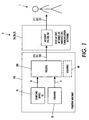
- Figure 1 depicts a printing machine 100.
- An included charging device 10 forms a charging device operating voltage 11.
- the printing machine 100 determines a charging device 10 pre-fault status condition based on an included method 200.
- Messages 110, 120 and 130 are sent to a user or operator 1 by means of any of an included display unit 2a, internet communication network 2b, or wireless or radio frequency communication network 2c.
- the printing machine 100 optionally includes an automatic cleaning system 30.
- a printing machine comprises a charging device that forms a variable charging device operating voltage.
- a charging device pre-fault status condition indicates that a charging device fault condition is likely to occur.
- the printing machine determines the charging device pre-fault status condition by a method comprising sampling the operating voltage; forming a slope value based on a charging device operating voltage rate of change per unit time; and determining when the slope value falls in a charging device pre-fault status range of values.
- the charging device pre-fault status determination is made, one of several messages is formed based on a current print count value. This message is then sent to a user or operator by means of an included display unit, internal communication network, or wireless or radio frequency communication network.
- a replacement message is sent to inform the user or operator that the charging device needs to be replaced. Otherwise, when the print count value does not fall in this range of values, a cleaning message is sent to inform the user or operator that the charging device needs to be cleaned.
- monitoring of the charging device pin to grid voltage time track enables the machine control system to anticipate an upcoming pin arc event. The operator can then be notified (before an arc occurs) to clean or replace the charging device.
- the pin scorotron charging device operates on a constant current of 2.085mA.
- the power supply output voltage varies to maintain this constant pin current.
- a pin voltage monitor signal is available to the machine control system along with the grid voltage.
- the pin to grid voltage can be calculated. Data show the pattern of decreasing pin to grid voltage and more voltage swinging before an arc occurs. New or well-cleaned charging devices do not exhibit this decrease in pin to grid voltages.
- the pin to grid voltage signature is used as a fault trigger.
- the fault is used to instruct the operator to clean the device before an arc occurs.
- the fault can be triggered if the pin to grid voltage variation is more than 100 volts in the last 60 seconds of operation.
- the fault can look at the High Frequency Service Interval cleaning interval remaining on the faulted charging device and instruct the operator to clean or replace the charging device depending on the run time since the last cleaning.
- a charging device that trips the "Anticipated Arc Soon" fault shortly after a previous cleaning would be replaced.
- a fault that occurs close to the cleaning interval would instruct the operator to clean the device.
- FIG. 1 there is depicted a printing machine 100 coupled to any of a display unit 2a, internet communication network 2b, or wireless or radio frequency communication network 2c. Items 2a, 2b and 2c are collectively designated reference number 2.
- the printing machine 100 comprises a copier.
- the printing machine 100 comprises a network printer.
- the printing machine 100 comprises a facsimile machine.
- Printing machine 100 includes a charging device 10 that forms a charging device operating voltage 11 that varies with time.
- the operating voltage 11 is based on a charging device 10 pin to grid differential voltage that results from constant pin to grid current operation.
- the printing machine 100 includes a counter 20 that forms a print count value 21.
- the print count value 21 is based on a total number of copies made using the charging device 10 since a first event of the charging device 10's installation or a second event of the charging device 10's most-recent cleaning, whichever event occurred last.
- the printing machine 100 determines a charging device 10 pre-fault status condition in accordance with an included method 200.
- the charging device 10 pre-fault status indicates that a changing device fault condition is likely to occur.
- the charging device 10 fault condition comprises a pin to grid arcing.
- various messages 110, 120 and 130 are formed and sent 211, 221 and 231 to a user or operator 1 by means of any of the items 2.
- FIGS 2A and 2B depict the method 200.
- the method begins with starting a print job, step 201. The method then goes to step 202.
- step 202 charging power is applied to the charging device 10. The method then goes to step 203.
- step 203 the charging device operating voltage 11 is sampled. The method then goes to step 204.
- step 204 a slope value is formed based on a charging device operating voltage 11 rate of change per unit time.
- step 204 the slope value is formed based on the optional steps 301, 302 and 303 that are described below in connection with Figure 3.
- step 204 the slope value is formed based on any suitable process.
- step 204 After forming the slope value in step 204, the process goes to step 205.
- step 205 it is determined when the slope value falls in a charging device pre-fault status range of values.
- the charging device pre-fault status range of values comprise slope values greater than a first threshold.
- the charging device pre-fault status range of values comprise slope values less than a second threshold.
- the charging device pre-fault status range of values comprise slope values greater than a first threshold and slope values less than a second threshold.
- the first threshold equals the absolute value of the second threshold.
- step 205 when the slope value falls in the charging device pre-fault status range of values, the step 205 determination is positive.
- step 205 positive determination the process goes in sequence to steps 210 and 211, depicted in Figure 2A, and then to step 217, depicted in Figure 2B. However, in another embodiment, after this step 205 positive determination the process goes directly to step 217, depicted in Figure 2B.
- step 205 when the slope value does not fall in the charging device pre-fault status range of values, the step 205 determination is negative and the process goes to step 206.
- step 206 the process determines when to continue the current printing job.
- step 290 charging power is removed from the charging device 10. The process then goes to step 299.
- step 299 the current printing job stops.
- Steps 210 and 211 are now described.
- step 210 a charging device pre-fault status message 110 is formed.
- the message 110 indicates that a charging device 10 fault condition is likely to occur. The process then goes to step 211.
- step 211 the charging device pre-fault status message 110 is sent to the user or operator 1 by means of any of the display unit 2a, the internet communication network 2b or the wireless or radio frequency communication network 2c. The process then goes to step 217, depicted in Figure 2B.
- step 217 a current print count value 21 is formed.
- the current print count value 21 is formed by an included counter 20.
- the print count value 21 is formed by any suitable means.
- step 218 it is determined when the print count value 21 falls in a charging device replacement range of values.
- step 218 when the print count value 21 falls in the charging device replacement range of values, the step 218 determination is positive and the process goes in sequence to steps 220 and 221.
- step 220 a charging device replacement message 120 is formed.
- the charging device replacement message 120 indicates that the charging device 10 needs to be replaced. The process then goes to step 221.
- step 221 the charging device replacement message 120 is sent to the user or operator 1 by means of any of the display unit 2a, the internet communication network 2b or the wireless or radio frequency communication network 2c.
- step 218 when the print count value 21 does not fall in the charging device replacement range of values, the step 218 determination is negative and the process goes in sequence to steps 230 and 231.
- step 230 a charging device cleaning message 130 is formed.
- the charging device cleaning message 130 indicates that the charging device 10 needs to be cleaned. The process then goes to step 231.
- step 231 the charging device cleaning message 130 is sent to the user or operator 1 by means of any of the display unit 2a, the internet communication network 2b or the wireless or radio frequency communication network 2c.
- step 204 of Figure 2A there is depicted an optional embodiment of the step 204 of Figure 2A.
- steps 301, 302 and 303 comprise one possible method to form the slope value in step 204 of Figure 2A.
- step 301 in one embodiment, the process forms a first charging device operating voltage 11 value, V1, at a first time, T1. (Note that an alternate embodiment of step 301 is described below.) The process then goes to step 302.
- step 302 the process forms a second charging device operating voltage 11 value, V2, at a second time, T2. The process then goes to step 303.
- step 303 the process forms a slope value equal to a ratio of a difference of the second charging device operating voltage 11 value, V2, and the first charging device operating voltage 11 value, V1 and a difference of the second time, T2, and the first time, T1.
- the process forms a slope value equal to (V2-V1) divided by (T2-T1) .
- step 301 the first charging device operating voltage 11 value, V1 is set to the value of the second charging device operating voltage 11 value, V2, that was formed in the prior step 302 in the prior iteration of the sequence of steps 301-303, and the first operating time, T1, is set to the second time, T2, that was formed during the same prior step 302 in the same prior iteration of the sequence of steps 301-303.
- the charging device replacement range of values is based on a charging device 10 target cleaning interval.
- the target cleaning interval is 1,000 copies and the charging device replacement range of values is less than 500 copies.
- step 218 determines that the print count value (490 copies) falls in the replacement range of values (less than 500 copies). As a result, the step 218 determination is positive, and so a charging device replacement message 120 is formed by step 220 and sent by step 221 to the user or operator 1.
- step 218 determines that the print count value (910 copies) does not fall in the replacement range of values (less than 500 copies) . As a result, the step 218 determination is negative, and so a charging device cleaning message 130 is formed by step 230 and sent by step 231 to the user or operator 1.
- the printing machine 100 comprises an automatic cleaning system 30.
- the pre-fault status determining step 205 depicted in Figure 2A, is used to trigger the cleaning cycle on the next cycle down, this triggering depicted as step 401 in Figure 4.
- a method 200 of determining a charging device 10 pre-fault status the charging device 10 forming a charging device operating voltage 11 that varies with time, the charging device 10 comprising an included printing machine 100, the method 200 comprising sampling (step 203) the charging device operating voltage 11, forming (step 204) a slope value based on a charging device operating voltage 11 rate of change per unit time, and determining (step 205) when the slope value falls in a charging device pre-fault status range of values.
- a printing machine 100 comprising a charging device 10, the charging device 10 forming a charging device operating voltage 11 that varies with time, the printing machine 100 arranged to determine a charging device 10 pre-fault status in accordance with a method 200, the method 200 comprising sampling (step 203) the charging device operating voltage 11, forming (step 204) a slope value based on an charging device operating voltage 11 rate of change per unit time, and determining (step 205) when the slope value falls in a charging device pre-fault status range of values.
- a method 200 of forming a charging device 10 service message (the charging device replacement message 120 and the charging device cleaning message 130) based on a charging device 10 operating voltage 11 that varies with time, the charging device 10 comprising an included printing machine 100, the method 200 comprising sampling (step 203) the charging device operating voltage 11, forming (step 204) a slope value based on a charging device operating voltage 11 rate of change per unit time, and forming (step 220 and step 230) a charging device service message (the charging device replacement message 120 and the charging device cleaning message 130) when (step 205 determines that) the slope value falls in a charging device pre-fault status range of values.
- a method 200 of triggering 401 a cleaning cycle based on a charging device 10 operating voltage 11 that varies with time the charging device 10 comprising an included printing machine 100, the method 200 comprising sampling (step 203) the charging device operating voltage 11, forming (step 204) a slope value based on a charging device operating voltage 11 rate of change per unit time, and triggering 401 a cleaning cycle in an included automatic cleaning system 30 when (step 205 determines that) the slope value falls in a charging device pre-fault status range of values.
- a printing machine comprises a charging device that forms a variable operating voltage.
- a charging device pre-fault status condition is determined by sampling the charging device operating voltage, forming a slope value based on a charging device operating voltage rate of change per unit time, and determining when the slope value falls in a charging device pre-fault status range of values.
- a message is formed based on a current print count value. This message is then sent to a user or operator.
- a replacement message is sent to inform that the charging device needs to be replaced. Otherwise, when the print count value does not fall in this range of values, a cleaning message is sent to inform that the charging device needs to be cleaned.
Landscapes
- Physics & Mathematics (AREA)
- Engineering & Computer Science (AREA)
- General Physics & Mathematics (AREA)
- Microelectronics & Electronic Packaging (AREA)
- Plasma & Fusion (AREA)
- Control Or Security For Electrophotography (AREA)
- Charge And Discharge Circuits For Batteries Or The Like (AREA)
- Electrostatic Charge, Transfer And Separation In Electrography (AREA)
- Accessory Devices And Overall Control Thereof (AREA)
Abstract
Description
- It is known that some xerographic engines have a problem with frequent DC pin scorotron "pin arcs". The root cause is believed to be as a result of pin and/or grid contamination. Contamination can be the result of fuser silicone oil volitles getting into the xerographic cavity, which form silica dendrites on the pins and/or grids of charging devices. There is also the possibility of pin and/or grid contamination with paper dust, toner and or toner additives. Pin scorotrons are typically operated under closed loop feedback control with a constant current maintained between the pins and grid. The voltage required to maintain this constant current is called the "operating voltage". Pin and/or grid contamination will cause a variation in this operating voltage. Furthermore the contamination can vary in its electrical conductivity as a function device operation history (powered/unpowered). This contamination conductivity variation is likely the root cause of the operating voltage variation.
- When a pin to grid arc occurs, the print engine does an immediate hard-down, requiring clearing of the paper path, a time consuming job. The arc energy is high enough to disrupt communications, which can require a re-boot to restore the machine to operation. Regardless of the mature machine interval between arcs, it is advantageous to predict when a pin arc is likely to occur.
- In a first aspect of the invention, there is described a method of determining a charging device pre-fault status, the charging device forming a charging device operating voltage that varies with time, the charging device comprising an included printing machine, the method comprising sampling the charging device operating voltage, forming a slope value based on a charging device operating voltage rate of change per unit time, and determining when the slope value falls in a charging device pre-fault status range of values.
- In a second aspect of the invention, there is described a printing machine comprising a charging device, the charging device forming a charging device operating voltage that varies with time, the printing machine arranged to determine a charging device pre-fault status in accordance with a method, the method comprising sampling the charging device operating voltage, forming a slope value based on an charging device operating voltage rate of change per unit time, and determining when the slope value falls in a charging device pre-fault status range of values.
- In a third aspect of the invention, there is described a method of forming a charging device service message based on a charging device operating voltage that varies with time, the charging device comprising an included printing machine, the method comprising sampling the charging device operating voltage, forming a slope value based on a charging device operating voltage rate of change per unit time, and forming a charging device service message when the slope value falls in a charging device pre-fault status range of values.
- In a fourth aspect of the invention, there is described a method of triggering a cleaning cycle based on a charging device operating voltage that varies with time, the charging device comprising an included printing machine, the method comprising sampling the charging device operating voltage, forming a slope value based on a charging device operating voltage rate of change per unit time, and triggering a cleaning cycle in an included automatic cleaning system when the slope value falls in a charging device pre-fault status range of values.
- A particular embodiment will now be described with reference to the accompanying drawings, in which:-
- Figure 1 is a block diagram of a printing machine;
- Figures 2A and B join together to form a flow diagram of a method of detecting a charging device pre-fault status;
- Figure 3 is a flow diagram of
step 204 shown in Figure 2A; and, - Figure 4 is an optical embodiment of
step 204 in Figure 2A. -
- Figure 1 depicts a
printing machine 100. An includedcharging device 10 forms a charging device operating voltage 11. Theprinting machine 100 determines acharging device 10 pre-fault status condition based on an includedmethod 200.Messages operator 1 by means of any of an includeddisplay unit 2a,internet communication network 2b, or wireless or radiofrequency communication network 2c. Theprinting machine 100 optionally includes anautomatic cleaning system 30. - Briefly, a printing machine comprises a charging device that forms a variable charging device operating voltage. A charging device pre-fault status condition indicates that a charging device fault condition is likely to occur. The printing machine determines the charging device pre-fault status condition by a method comprising sampling the operating voltage; forming a slope value based on a charging device operating voltage rate of change per unit time; and determining when the slope value falls in a charging device pre-fault status range of values. When the charging device pre-fault status determination is made, one of several messages is formed based on a current print count value. This message is then sent to a user or operator by means of an included display unit, internal communication network, or wireless or radio frequency communication network. When the print count value falls in a charging device replacement range of values, a replacement message is sent to inform the user or operator that the charging device needs to be replaced. Otherwise, when the print count value does not fall in this range of values, a cleaning message is sent to inform the user or operator that the charging device needs to be cleaned.
- As a result of the present invention, monitoring of the charging device pin to grid voltage time track enables the machine control system to anticipate an upcoming pin arc event. The operator can then be notified (before an arc occurs) to clean or replace the charging device.
- In one typical printing machine, the pin scorotron charging device operates on a constant current of 2.085mA. The power supply output voltage varies to maintain this constant pin current. A pin voltage monitor signal is available to the machine control system along with the grid voltage. The pin to grid voltage can be calculated. Data show the pattern of decreasing pin to grid voltage and more voltage swinging before an arc occurs. New or well-cleaned charging devices do not exhibit this decrease in pin to grid voltages.
- In accordance with the present invention, the pin to grid voltage signature is used as a fault trigger. The fault is used to instruct the operator to clean the device before an arc occurs. For example, the fault can be triggered if the pin to grid voltage variation is more than 100 volts in the last 60 seconds of operation.
- Alternatively, the fault can look at the High Frequency Service Interval cleaning interval remaining on the faulted charging device and instruct the operator to clean or replace the charging device depending on the run time since the last cleaning. A charging device that trips the "Anticipated Arc Soon" fault shortly after a previous cleaning would be replaced. A fault that occurs close to the cleaning interval would instruct the operator to clean the device.
- Referring now to Figure 1, there is depicted a
printing machine 100 coupled to any of adisplay unit 2a,internet communication network 2b, or wireless or radiofrequency communication network 2c.Items reference number 2. - In a first embodiment, the
printing machine 100 comprises a copier. - In a second embodiment, the
printing machine 100 comprises a network printer. - In a third embodiment, the
printing machine 100 comprises a facsimile machine. -
Printing machine 100 includes acharging device 10 that forms a charging device operating voltage 11 that varies with time. - In one embodiment, the operating voltage 11 is based on a
charging device 10 pin to grid differential voltage that results from constant pin to grid current operation. - In one embodiment, the
printing machine 100 includes acounter 20 that forms aprint count value 21. - In one embodiment, the
print count value 21 is based on a total number of copies made using thecharging device 10 since a first event of thecharging device 10's installation or a second event of thecharging device 10's most-recent cleaning, whichever event occurred last. - The
printing machine 100 determines acharging device 10 pre-fault status condition in accordance with an includedmethod 200. Thecharging device 10 pre-fault status indicates that a changing device fault condition is likely to occur. - In one embodiment, the
charging device 10 fault condition comprises a pin to grid arcing. - In accordance with the
method 200,various messages operator 1 by means of any of theitems 2. - Figures 2A and 2B depict the
method 200. - Referring now to Figure 2A, the method begins with starting a print job,
step 201. The method then goes tostep 202. - In
step 202 charging power is applied to thecharging device 10. The method then goes tostep 203. - In
step 203 the charging device operating voltage 11 is sampled. The method then goes to step 204. - In step 204 a slope value is formed based on a charging device operating voltage 11 rate of change per unit time.
- In one embodiment, in
step 204 the slope value is formed based on theoptional steps - In another embodiment, in
step 204 the slope value is formed based on any suitable process. - After forming the slope value in
step 204, the process goes to step 205. - In
step 205 it is determined when the slope value falls in a charging device pre-fault status range of values. - In one embodiment, the charging device pre-fault status range of values comprise slope values greater than a first threshold.
- In another embodiment, the charging device pre-fault status range of values comprise slope values less than a second threshold.
- In still another embodiment, the charging device pre-fault status range of values comprise slope values greater than a first threshold and slope values less than a second threshold. Optionally, in one embodiment, the first threshold equals the absolute value of the second threshold.
- Still referring to step 205, when the slope value falls in the charging device pre-fault status range of values, the
step 205 determination is positive. - In one embodiment, after this
step 205 positive determination the process goes in sequence tosteps step 205 positive determination the process goes directly to step 217, depicted in Figure 2B. - Still referring to step 205, when the slope value does not fall in the charging device pre-fault status range of values, the
step 205 determination is negative and the process goes to step 206. - In
step 206, the process determines when to continue the current printing job. - When the current printing job continues, the
determination 206 is positive and the process returns to step 203. - Otherwise, when the current printing job does not continue, the
determination 206 is negative and the process goes to step 290. - In
step 290 charging power is removed from the chargingdevice 10. The process then goes to step 299. - In
step 299 the current printing job stops. -
Steps - In step 210 a charging device pre-fault status message 110 is formed. The message 110 indicates that a charging
device 10 fault condition is likely to occur. The process then goes to step 211. - In
step 211 the charging device pre-fault status message 110 is sent to the user oroperator 1 by means of any of thedisplay unit 2a, theinternet communication network 2b or the wireless or radiofrequency communication network 2c. The process then goes to step 217, depicted in Figure 2B. - Referring now to Figure 2B, in step 217 a current
print count value 21 is formed. - In one embodiment, the current
print count value 21 is formed by an includedcounter 20. - In another embodiment, the
print count value 21 is formed by any suitable means. - The process then goes to step 218.
- In
step 218 it is determined when theprint count value 21 falls in a charging device replacement range of values. - Still referring to step 218, when the
print count value 21 falls in the charging device replacement range of values, thestep 218 determination is positive and the process goes in sequence tosteps - In step 220 a charging
device replacement message 120 is formed. The chargingdevice replacement message 120 indicates that the chargingdevice 10 needs to be replaced. The process then goes to step 221. - In
step 221 the chargingdevice replacement message 120 is sent to the user oroperator 1 by means of any of thedisplay unit 2a, theinternet communication network 2b or the wireless or radiofrequency communication network 2c. - Still referring to step 218, when the
print count value 21 does not fall in the charging device replacement range of values, thestep 218 determination is negative and the process goes in sequence tosteps - In step 230 a charging
device cleaning message 130 is formed. The chargingdevice cleaning message 130 indicates that the chargingdevice 10 needs to be cleaned. The process then goes to step 231. - In
step 231 the chargingdevice cleaning message 130 is sent to the user oroperator 1 by means of any of thedisplay unit 2a, theinternet communication network 2b or the wireless or radiofrequency communication network 2c. - Referring to Figure 3 there is depicted an optional embodiment of the
step 204 of Figure 2A. Thus, the depictedsteps step 204 of Figure 2A. - Referring to step 301, in one embodiment, the process forms a first charging device operating voltage 11 value, V1, at a first time, T1. (Note that an alternate embodiment of
step 301 is described below.) The process then goes to step 302. - In
step 302 the process forms a second charging device operating voltage 11 value, V2, at a second time, T2. The process then goes to step 303. - In
step 303 the process forms a slope value equal to a ratio of a difference of the second charging device operating voltage 11 value, V2, and the first charging device operating voltage 11 value, V1 and a difference of the second time, T2, and the first time, T1. Thus, instep 303 the process forms a slope value equal to (V2-V1) divided by (T2-T1) . - Referring still to Figure 3, with momentary cross-reference back to Figure 2A, it will be understood that the sequence of steps 301-303 is repeatedly performed while the current printing job continues to run. Hence, in an alternate embodiment, in
step 301 the first charging device operating voltage 11 value, V1, is set to the value of the second charging device operating voltage 11 value, V2, that was formed in theprior step 302 in the prior iteration of the sequence of steps 301-303, and the first operating time, T1, is set to the second time, T2, that was formed during the sameprior step 302 in the same prior iteration of the sequence of steps 301-303. - Referring again to
steps 218, in one embodiment, the charging device replacement range of values is based on acharging device 10 target cleaning interval. - For example, in one embodiment the target cleaning interval is 1,000 copies and the charging device replacement range of values is less than 500 copies.
- In this example, first assume that when the charging device pre-fault status is determined to exist by
step 205, the corresponding print count value determined bystep 217 is 490 copies. In this case,step 218 determines that the print count value (490 copies) falls in the replacement range of values (less than 500 copies). As a result, thestep 218 determination is positive, and so a chargingdevice replacement message 120 is formed bystep 220 and sent bystep 221 to the user oroperator 1. - In this same example, now second assume that when the charging device pre-fault status is determined to exist by
step 205, the corresponding print count value determined bystep 217 is 910 copies. In this case,step 218 determines that the print count value (910 copies) does not fall in the replacement range of values (less than 500 copies) . As a result, thestep 218 determination is negative, and so a chargingdevice cleaning message 130 is formed bystep 230 and sent bystep 231 to the user oroperator 1. - Referring again to Figure 1, in one embodiment, the
printing machine 100 comprises anautomatic cleaning system 30. In this embodiment, the pre-faultstatus determining step 205, depicted in Figure 2A, is used to trigger the cleaning cycle on the next cycle down, this triggering depicted asstep 401 in Figure 4. - Thus, there has been described a
method 200 of determining a chargingdevice 10 pre-fault status, the chargingdevice 10 forming a charging device operating voltage 11 that varies with time, the chargingdevice 10 comprising an includedprinting machine 100, themethod 200 comprising sampling (step 203) the charging device operating voltage 11, forming (step 204) a slope value based on a charging device operating voltage 11 rate of change per unit time, and determining (step 205) when the slope value falls in a charging device pre-fault status range of values. - Further, there has been described a
printing machine 100 comprising a chargingdevice 10, the chargingdevice 10 forming a charging device operating voltage 11 that varies with time, theprinting machine 100 arranged to determine acharging device 10 pre-fault status in accordance with amethod 200, themethod 200 comprising sampling (step 203) the charging device operating voltage 11, forming (step 204) a slope value based on an charging device operating voltage 11 rate of change per unit time, and determining (step 205) when the slope value falls in a charging device pre-fault status range of values. - Further, there has been described a
method 200 of forming a chargingdevice 10 service message (the chargingdevice replacement message 120 and the charging device cleaning message 130) based on acharging device 10 operating voltage 11 that varies with time, the chargingdevice 10 comprising an includedprinting machine 100, themethod 200 comprising sampling (step 203) the charging device operating voltage 11, forming (step 204) a slope value based on a charging device operating voltage 11 rate of change per unit time, and forming (step 220 and step 230) a charging device service message (the chargingdevice replacement message 120 and the charging device cleaning message 130) when (step 205 determines that) the slope value falls in a charging device pre-fault status range of values. - Further, there has been described a
method 200 of triggering 401 a cleaning cycle based on acharging device 10 operating voltage 11 that varies with time, the chargingdevice 10 comprising an includedprinting machine 100, themethod 200 comprising sampling (step 203) the charging device operating voltage 11, forming (step 204) a slope value based on a charging device operating voltage 11 rate of change per unit time, and triggering 401 a cleaning cycle in an includedautomatic cleaning system 30 when (step 205 determines that) the slope value falls in a charging device pre-fault status range of values. - The table below lists the drawing element reference numbers together with their corresponding written description:
Number: Description: 1 operator or user 2a display unit 2b internet communication network 2c wireless or radio frequency communication network 2 any of 2a, 2b and 2c 10 charging device 11 operating voltage 12 charging device pin to grid differential voltage 20 print counter 21 print count value 30 optional automatic cleaning system 100 printing machine (copier, network printer or facsimile) 110 charging device pre-fault status message 120 charging device replacement message 130 charging device cleaning message 200 method of determining a charging device pre-fault status 201 start print job 202 charging device power = on 203 sampling the charging device operating voltage 204 forming a slope value 301 forming a first charging device operating voltage value at a first time 302 forming a second charging device operating voltage value at a second time 303 forming a ratio of the difference of the second and first charging device operating voltage values and a difference of the second and first times 205 determining when the slope value falls in a charging device pre-fault status range of values 206 continue job? 207 forming a print count value 208 determining when the print count value falls in a charging device replacement range of values 210 forming a charging device pre-fault status message 211 sending the charging device pre-fault status message 220 forming a charging device replacement message 221 sending the charging device replacement message 230 forming a charging device cleaning message 231 sending the charging device cleaning message 290 charging device power = off 299 stop print job 401 trigger the cleaning cycle on the next cycle down - A printing machine comprises a charging device that forms a variable operating voltage. A charging device pre-fault status condition is determined by sampling the charging device operating voltage, forming a slope value based on a charging device operating voltage rate of change per unit time, and determining when the slope value falls in a charging device pre-fault status range of values. When the pre-fault status determination is made, a message is formed based on a current print count value. This message is then sent to a user or operator. When the print count value falls in a charging device replacement range of values, a replacement message is sent to inform that the charging device needs to be replaced. Otherwise, when the print count value does not fall in this range of values, a cleaning message is sent to inform that the charging device needs to be cleaned.
Claims (10)
- A method of determining a charging device pre-fault status, the charging device forming a charging device operating voltage that varies with time, the charging device comprising an included printing machine, the method comprising:sampling the charging device operating voltage;forming a slope value based on a charging device operating voltage rate of change per unit time; anddetermining when the slope value falls in a charging device pre-fault status range of values.
- The method according to claim 1, wherein the charging device operating voltage based on a charging device pin to grid differential voltage.
- The method according to claim 1 or 2, wherein the charging device pre-fault status range of values comprises slope values greater than a first threshold and less than a second threshold.
- A method according to any of the preceding claims, including generating a charging device pre-fault status message indicating that a charging device fault condition is likely to occur.
- A method according to any of the preceding claims, wherein the slope value is based on forming a first charging device operating voltage value at a first time, forming a second charging device operating voltage value at a second time and forming a ratio of a difference of the second and first charging device operating voltage values and a difference of the second and first times.
- A method of according to claim 5, including generating a charging device pre-fault status message when the slope value falls in the charging device pre-fault status range of values.
- A method of according to any one of the preceding claims, wherein the fault condition comprises pin to grid arcing.
- A method of forming a charging device service message based on a charging device operating voltage that varies with time, the charging device comprising an included printing machine, the method comprising:sampling the charging device operating voltage;forming a slope value based on a charging device operating voltage rate of change per unit time; andforming a charging device service message when the slope value falls in a charging device pre-fault status range of values.
- A method according to claim 8, including forming a print count value and forming the charging device service message based on the print count value.
- A method of triggering a cleaning cycle based on a charging device operating voltage that varies with time, the charging device comprising an included printing machine, the method comprising:sampling the charging device operating voltage;forming a slope value based on a charging device operating voltage rate of change per unit time; andtriggering a cleaning cycle in an included automatic cleaning system when the slope value falls in a charging device pre-fault status range of values.
Applications Claiming Priority (2)
| Application Number | Priority Date | Filing Date | Title |
|---|---|---|---|
| US462329 | 2003-06-16 | ||
| US10/462,329 US6711363B1 (en) | 2003-06-16 | 2003-06-16 | Method of determining a charging device pre-fault status, a printing machine arranged with the same method, a method of forming a charging device service message and a method of triggering a cleaning cycle |
Publications (2)
| Publication Number | Publication Date |
|---|---|
| EP1489465A1 true EP1489465A1 (en) | 2004-12-22 |
| EP1489465B1 EP1489465B1 (en) | 2013-03-06 |
Family
ID=31978870
Family Applications (1)
| Application Number | Title | Priority Date | Filing Date |
|---|---|---|---|
| EP04253374A Expired - Lifetime EP1489465B1 (en) | 2003-06-16 | 2004-06-07 | Determining a charging device pre-fault status |
Country Status (6)
| Country | Link |
|---|---|
| US (1) | US6711363B1 (en) |
| EP (1) | EP1489465B1 (en) |
| JP (1) | JP2005031650A (en) |
| CN (1) | CN100454159C (en) |
| BR (1) | BRPI0402222A (en) |
| CA (1) | CA2470688C (en) |
Families Citing this family (6)
| Publication number | Priority date | Publication date | Assignee | Title |
|---|---|---|---|---|
| US20060045559A1 (en) * | 2004-08-31 | 2006-03-02 | Xerox Corporation | Method of actuating a cleaning system and a printing machine including the same |
| US7664423B2 (en) * | 2004-10-29 | 2010-02-16 | Murata Machinery, Ltd. | Image forming device including a cleaning member |
| JP7020768B2 (en) * | 2016-05-27 | 2022-02-16 | シャープ株式会社 | Image forming device and notification method of guidance display |
| JP6797700B2 (en) * | 2017-01-18 | 2020-12-09 | キヤノン株式会社 | Image forming device |
| CN111624428B (en) * | 2020-06-10 | 2021-11-26 | 南方电网科学研究院有限责任公司 | Fault diagnosis device of alternating-current charging pile supporting remote cloud service |
| JP2024098578A (en) * | 2023-01-11 | 2024-07-24 | 東芝テック株式会社 | Image forming apparatus and program |
Citations (2)
| Publication number | Priority date | Publication date | Assignee | Title |
|---|---|---|---|---|
| US4777554A (en) * | 1982-10-18 | 1988-10-11 | Tokyo Shibaura Denki Kabushiki Kaisha | Method and apparatus for detecting charger abnormality |
| US6449447B1 (en) * | 2000-08-01 | 2002-09-10 | Heidelberger Druckmaschinen Ag | Image-forming machine having charger cleaning activation after an arcing fault and related method |
Family Cites Families (7)
| Publication number | Priority date | Publication date | Assignee | Title |
|---|---|---|---|---|
| JP2685814B2 (en) * | 1988-06-23 | 1997-12-03 | 株式会社リコー | Image forming device |
| US5191293A (en) * | 1991-08-30 | 1993-03-02 | Xerox Corporation | Park and ride method for determining photoreceptor potentials |
| EP0698831B1 (en) * | 1994-08-22 | 2003-04-16 | Canon Kabushiki Kaisha | Method for controlling an image formation condition in an image forming apparatus |
| JPH09211938A (en) * | 1996-01-29 | 1997-08-15 | Canon Inc | Image forming device |
| JPH10260591A (en) * | 1997-03-19 | 1998-09-29 | Toshiba Corp | Image forming apparatus and adjustment method thereof |
| US6459273B1 (en) * | 1998-11-23 | 2002-10-01 | Siemens Energy & Automation, Inc. | Arc fault detector method |
| JP2000206769A (en) * | 1999-01-19 | 2000-07-28 | Fujitsu Ltd | Image forming device |
-
2003
- 2003-06-16 US US10/462,329 patent/US6711363B1/en not_active Expired - Fee Related
-
2004
- 2004-06-07 EP EP04253374A patent/EP1489465B1/en not_active Expired - Lifetime
- 2004-06-10 CA CA002470688A patent/CA2470688C/en not_active Expired - Fee Related
- 2004-06-15 CN CNB2004100592547A patent/CN100454159C/en not_active Expired - Fee Related
- 2004-06-15 JP JP2004177423A patent/JP2005031650A/en active Pending
- 2004-06-15 BR BR0402222-0A patent/BRPI0402222A/en not_active IP Right Cessation
Patent Citations (2)
| Publication number | Priority date | Publication date | Assignee | Title |
|---|---|---|---|---|
| US4777554A (en) * | 1982-10-18 | 1988-10-11 | Tokyo Shibaura Denki Kabushiki Kaisha | Method and apparatus for detecting charger abnormality |
| US6449447B1 (en) * | 2000-08-01 | 2002-09-10 | Heidelberger Druckmaschinen Ag | Image-forming machine having charger cleaning activation after an arcing fault and related method |
Also Published As
| Publication number | Publication date |
|---|---|
| EP1489465B1 (en) | 2013-03-06 |
| CA2470688C (en) | 2008-01-15 |
| CN100454159C (en) | 2009-01-21 |
| CN1584754A (en) | 2005-02-23 |
| US6711363B1 (en) | 2004-03-23 |
| BRPI0402222A (en) | 2005-01-25 |
| CA2470688A1 (en) | 2004-12-16 |
| JP2005031650A (en) | 2005-02-03 |
Similar Documents
| Publication | Publication Date | Title |
|---|---|---|
| EP1489465B1 (en) | Determining a charging device pre-fault status | |
| EP0898212B1 (en) | Method and apparatus for monitoring the cleaning performance to predict cleaner life | |
| JP6452548B2 (en) | Power supply apparatus and control method | |
| JP4867366B2 (en) | Life prediction system | |
| JP2017181991A (en) | Image forming device | |
| JP2013210622A (en) | Image forming apparatus | |
| JP2004264859A (en) | Electrophotographic measurement system | |
| US7116922B2 (en) | Charging apparatus | |
| JP2008077315A (en) | Information processing apparatus and information processing method | |
| US6370340B1 (en) | Method and apparatus for monitoring parameters corresponding to operation of an electrophotographic marking machine | |
| JP2018536538A (en) | Method and system for data acquisition for electrostatic precipitator control | |
| JP2009063780A (en) | Consumption power management system | |
| CN110007575B (en) | Image forming apparatus, control method thereof, and recording medium | |
| JP3610830B2 (en) | Power supply | |
| US20120078389A1 (en) | Communication system and control method therefor | |
| JP3216103B2 (en) | Life detection method for contact charging members | |
| US20060045559A1 (en) | Method of actuating a cleaning system and a printing machine including the same | |
| JP2006301367A (en) | Image forming apparatus | |
| EP1543385B1 (en) | ELECTROPHOTOGRAPHIC COLOR PRINTING APPARATUS with belt bias means | |
| KR102017061B1 (en) | Electric Precipitator using Load Balancing Control Process | |
| JP2004085721A (en) | Image forming apparatus | |
| US20040165900A1 (en) | Image forming apparatus | |
| JP6175884B2 (en) | Power supply monitoring device, image processing device | |
| JP5998898B2 (en) | Image forming apparatus | |
| JP2006349764A (en) | Image forming apparatus |
Legal Events
| Date | Code | Title | Description |
|---|---|---|---|
| PUAI | Public reference made under article 153(3) epc to a published international application that has entered the european phase |
Free format text: ORIGINAL CODE: 0009012 |
|
| AK | Designated contracting states |
Kind code of ref document: A1 Designated state(s): AT BE BG CH CY CZ DE DK EE ES FI FR GB GR HU IE IT LI LU MC NL PL PT RO SE SI SK TR |
|
| AX | Request for extension of the european patent |
Extension state: AL HR LT LV MK |
|
| 17P | Request for examination filed |
Effective date: 20050622 |
|
| AKX | Designation fees paid |
Designated state(s): DE FR GB |
|
| GRAP | Despatch of communication of intention to grant a patent |
Free format text: ORIGINAL CODE: EPIDOSNIGR1 |
|
| GRAS | Grant fee paid |
Free format text: ORIGINAL CODE: EPIDOSNIGR3 |
|
| GRAA | (expected) grant |
Free format text: ORIGINAL CODE: 0009210 |
|
| AK | Designated contracting states |
Kind code of ref document: B1 Designated state(s): DE FR GB |
|
| REG | Reference to a national code |
Ref country code: GB Ref legal event code: FG4D |
|
| REG | Reference to a national code |
Ref country code: DE Ref legal event code: R096 Ref document number: 602004041216 Country of ref document: DE Effective date: 20130502 |
|
| PLBE | No opposition filed within time limit |
Free format text: ORIGINAL CODE: 0009261 |
|
| STAA | Information on the status of an ep patent application or granted ep patent |
Free format text: STATUS: NO OPPOSITION FILED WITHIN TIME LIMIT |
|
| 26N | No opposition filed |
Effective date: 20131209 |
|
| REG | Reference to a national code |
Ref country code: DE Ref legal event code: R097 Ref document number: 602004041216 Country of ref document: DE Effective date: 20131209 |
|
| PGFP | Annual fee paid to national office [announced via postgrant information from national office to epo] |
Ref country code: GB Payment date: 20140527 Year of fee payment: 11 |
|
| PGFP | Annual fee paid to national office [announced via postgrant information from national office to epo] |
Ref country code: DE Payment date: 20140523 Year of fee payment: 11 |
|
| PGFP | Annual fee paid to national office [announced via postgrant information from national office to epo] |
Ref country code: FR Payment date: 20140620 Year of fee payment: 11 |
|
| REG | Reference to a national code |
Ref country code: DE Ref legal event code: R119 Ref document number: 602004041216 Country of ref document: DE |
|
| GBPC | Gb: european patent ceased through non-payment of renewal fee |
Effective date: 20150607 |
|
| REG | Reference to a national code |
Ref country code: FR Ref legal event code: ST Effective date: 20160229 |
|
| PG25 | Lapsed in a contracting state [announced via postgrant information from national office to epo] |
Ref country code: GB Free format text: LAPSE BECAUSE OF NON-PAYMENT OF DUE FEES Effective date: 20150607 Ref country code: DE Free format text: LAPSE BECAUSE OF NON-PAYMENT OF DUE FEES Effective date: 20160101 |
|
| PG25 | Lapsed in a contracting state [announced via postgrant information from national office to epo] |
Ref country code: FR Free format text: LAPSE BECAUSE OF NON-PAYMENT OF DUE FEES Effective date: 20150630 |