EP1489399A1 - Hierarchical lossless encoding/decoding method, hierarchical lossless encoding method, hierarchical lossless decoding method, its apparatus, and program - Google Patents
Hierarchical lossless encoding/decoding method, hierarchical lossless encoding method, hierarchical lossless decoding method, its apparatus, and program Download PDFInfo
- Publication number
- EP1489399A1 EP1489399A1 EP03710460A EP03710460A EP1489399A1 EP 1489399 A1 EP1489399 A1 EP 1489399A1 EP 03710460 A EP03710460 A EP 03710460A EP 03710460 A EP03710460 A EP 03710460A EP 1489399 A1 EP1489399 A1 EP 1489399A1
- Authority
- EP
- European Patent Office
- Prior art keywords
- low
- bit
- rate
- lossless
- encoded data
- Prior art date
- Legal status (The legal status is an assumption and is not a legal conclusion. Google has not performed a legal analysis and makes no representation as to the accuracy of the status listed.)
- Withdrawn
Links
Images




Classifications
-
- G—PHYSICS
- G10—MUSICAL INSTRUMENTS; ACOUSTICS
- G10L—SPEECH ANALYSIS TECHNIQUES OR SPEECH SYNTHESIS; SPEECH RECOGNITION; SPEECH OR VOICE PROCESSING TECHNIQUES; SPEECH OR AUDIO CODING OR DECODING
- G10L19/00—Speech or audio signals analysis-synthesis techniques for redundancy reduction, e.g. in vocoders; Coding or decoding of speech or audio signals, using source filter models or psychoacoustic analysis
-
- G—PHYSICS
- G10—MUSICAL INSTRUMENTS; ACOUSTICS
- G10L—SPEECH ANALYSIS TECHNIQUES OR SPEECH SYNTHESIS; SPEECH RECOGNITION; SPEECH OR VOICE PROCESSING TECHNIQUES; SPEECH OR AUDIO CODING OR DECODING
- G10L19/00—Speech or audio signals analysis-synthesis techniques for redundancy reduction, e.g. in vocoders; Coding or decoding of speech or audio signals, using source filter models or psychoacoustic analysis
- G10L19/0017—Lossless audio signal coding; Perfect reconstruction of coded audio signal by transmission of coding error
-
- G—PHYSICS
- G11—INFORMATION STORAGE
- G11B—INFORMATION STORAGE BASED ON RELATIVE MOVEMENT BETWEEN RECORD CARRIER AND TRANSDUCER
- G11B20/00—Signal processing not specific to the method of recording or reproducing; Circuits therefor
- G11B20/10—Digital recording or reproducing
-
- H—ELECTRICITY
- H03—ELECTRONIC CIRCUITRY
- H03M—CODING; DECODING; CODE CONVERSION IN GENERAL
- H03M7/00—Conversion of a code where information is represented by a given sequence or number of digits to a code where the same, similar or subset of information is represented by a different sequence or number of digits
- H03M7/30—Compression; Expansion; Suppression of unnecessary data, e.g. redundancy reduction
Definitions
- the present invention relates to a hierarchical lossless encoding and decoding technology for digital signals such as of music data, audio data, or the like.
- One process for lossless encoding of audio signals such as music signals is a hierarchical lossless encoding process.
- Data encoded by the hierarchical lossless encoding process is characterized in that it includes low-bit-rate non-lossless encoded data hierarchically as part thereof.
- a summary of the hierarchical lossless encoding process is described in IEEE Signal Processing Magazine, pp. 21 - 32, July 2001.
- the conventional hierarchical lossless encoding and decoding technology will briefly be described below with reference to Figs. 1 and 2 of the accompanying drawings which show a conventional hierarchical lossless encoding apparatus and a conventional hierarchical lossless decoding apparatus, respectively.
- an input signal from input terminal 100 is supplied to low-bit-rate encoder 101 and delay compensator 102.
- the input signal supplied to low-bit-rate encoder 101 is encoded thereby and is output as low-bit-rate encoded data to output terminal 105 and low-bit-rate decoder 103.
- Low-bit-rate decoder 103 decodes the supplied low-bit-rate encoded data into a low-bit-rate decoded signal.
- the input signal supplied to delay compensator 102 is delayed by a time corresponding to a delay caused by the low-bit-rate encoding and decoding process (a processing time required by low-bit-rate encoder 101 and low-bit-rate decoder 103), and thereafter output as a delayed input signal.
- Lossless encoder 104 encodes a differential signal, which is produced by subtracting the low-bit-rate decoded signal from the delayed input signal, according to a lossless encoding process, and outputs lossless encoded data to output terminal 106.
- low-bit-rate encoded data from input terminal 200 is decoded into a low-bit-rate decoded signal by low-bit-rate decoder 201.
- Lossless encoded data from input terminal 202 is decoded into a differential signal by lossless decoder 203.
- the low-bit-rate decoded signal is output to output terminal 204, and added to the differential signal from lossless decoder 203, producing a sum signal that is output as a lossless reproduced signal to output terminal 205.
- the lossless reproduced signal is the same as the input signal insofar as the low-bit-rate decoded signal in the decoding apparatus is identical to the low-bit-rate decoded signal in the encoding apparatus.
- the low-bit-rate encoding and decoding process may be a transform encoding and decoding process or a CELP (Code Excited Linear Prediction) encoding and decoding process.
- the transform encoding and decoding process will not be described in detail below as reference can be made to Proceedings on ICASSP, pp. 1093 - 1096, Apr. 1990 for details of the transform encoding and decoding process.
- the CELP encoding and decoding process will not be described in detail below as reference can be made to Proceedings on ICASSP, pp. 937 - 940, Mar. 1985 for details of the CELP encoding and decoding process.
- the lossless encoding and decoding process will not be described in detail below as reference can be made to IEEE Signal Processing Magazine, pp. 21 - 32, July 2001 for details of the lossless encoding and decoding process.
- the conventional hierarchical lossless encoding and decoding process is problematic in that if the low-bit-rate decoded signal in the decoding apparatus is not identical to the low-bit-rate decoded signal in the encoding apparatus, then the lossless reproduced signal is not the same as the input signal. This problem occurs primarily when the processing accuracy in the low-bit-rate decoder in the encoding apparatus and the processing accuracy in the low-bit-rate decoder in the decoding apparatus are different from each other.
- each of the low-bit-rate decoded signals in the encoding apparatus and the decoding apparatus may possibly have a decoding error of ⁇ 1 at maximum with respect to the reference decoded signal, and hence the total error of the low-bit-rate decoded signals in the encoding apparatus and the decoding apparatus may possibly reach ⁇ 2 at maximum.
- the lossless reproduced signal derived from the low-bit-rate decoded signal may not be identical to the input signal.
- a corrective information extractor in an encoding apparatus extracts corrective information from a low-bit-rate decoded signal in view of a maximum value that can occur in a low-bit-rate decoder, and a corrector in a decoding apparatus corrects a low-bit-rate decoded signal based on the corrective information. Since the low-bit-rate decoded signal in the encoding apparatus and the low-bit-rate decoded signal in the decoding apparatus are thus made identical to each other, the lossless reproduced signal is made identical to the input signal.
- Fig. 3 is a block diagram of hierarchical lossless encoding apparatus 1 according to a first embodiment of the present invention
- Fig. 4 is a block diagram of hierarchical lossless decoding apparatus 2 according to the first embodiment of the present invention.
- hierarchical lossless encoding apparatus 1 comprises input terminal 100, low-bit-rate encoder 101, delay compensator 102, low-bit-rate decoder 103, lossless encoder 104, corrective information extractor 107, adder ADD1, output terminals 105, 106, 108, and recording medium K1.
- Hierarchical lossless encoding apparatus 1 according to the present embodiment differs from the conventional apparatus shown in Fig. 1 in that corrective information extractor 107, output terminal 108, and recording medium K1 are added to the conventional apparatus.
- Recording medium K1 comprises a disk, a semiconductor memory, or another recording medium, and stores a program for enabling a computer to function as hierarchical lossless encoding apparatus 1.
- the program is read by the computer and controls its operation to realize low-bit-rate encoder 101, delay compensator 102, low-bit-rate decoder 103, lossless encoder 104, corrective information extractor 107, and adder ADD1 on the computer.
- Hierarchical lossless decoding apparatus 2 comprises input terminals 200, 202, 206, low-bit-rate decoder 201, lossless decoder 203, corrector 207, adder ADD2, output terminals 204, 205, and recording medium K2.
- Hierarchical lossless decoding apparatus 2 according to the present embodiment differs from the conventional apparatus shown in Fig. 2 in that corrector 207, input terminal 206, and recording medium K2 added to the conventional apparatus.
- Recording medium K1 comprises a disk, a semiconductor memory, or another recording medium, and stores a program for enabling a computer to function as hierarchical lossless decoding apparatus 2. The program is read by the computer and controls its operation to realize low-bit-rate decoder 201, lossless decoder 203, corrector 207, and adder ADD2 on the computer.
- Corrective information extractor 107 in hierarchical lossless encoding apparatus 1 extracts corrective information rx in view of a maximum error of low-bit-rate decoder 103 from a low-bit-rate decoded signal that has been calculated by low-bit-rate decoder 103 in the same manner as heretofore, and outputs corrective information rx to output terminal 108.
- Corrective information rx may employ a value represented by low-order M bits of a sampled value of a low-bit-rate decoded signal.
- the absolute value E of maximum errors is preset in the present embodiment, the absolute value E may be variable depending on the amplitude of the input signal. If the absolute value E is variable, then the setting information of the absolute value needs to be indicated to the decoding apparatus through a transmitting means or a recording medium.
- the number M of bits of corrective information rx can be smaller as E is smaller as can be understood from the formula (1). Therefore, the number of transmitted bits can be reduced by making E variable depending on the amplitude of the input signal and transmitting corrective information rx having the number of bits depending on E to the decoding apparatus.
- Low-bit-rate encoded data, lossless encoded data, and corrective information rx that are output from respective output terminals 105, 106, 108 of hierarchical lossless encoding apparatus 1 are inputted respectively to input terminals 200, 202, 206 of hierarchical lossless decoding apparatus 2.
- Corrector 207 of hierarchical lossless decoding apparatus 2 corrects a low-bit-rate decoded signal calculated by low-bit-rate decoder 201 in the same manner as heretofore, based on corrective information rx inputted from input terminal 206, and outputs the corrected low-bit-rate decoded signal.
- the corrected low-bit-rate decoded signal and a differential signal calculated by lossless decoder in the same manner as heretofore are added to each other by adder ADD2, and the sum is output as a lossless reproduced signal to output terminal 205.
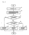
- Corrector 207 operates per sample of the low-bit-rate decoded signal. An example of operation of corrector 207 will be described in detail below with reference to a flowchart shown in Fig. 5.
- mt 2 M
- step A3 Value xlow of low-order M bits of the low-bit-rate decoded signal output from low-bit-rate decoder 201 and corrective information rx inputted from input terminal 206 are compared with each other to check if the inequality (7) shown below is satisfied or not (step A3). Specifically, in step A3, it is checked whether or not a carry occurs on the low-order (M+1)th bit of the low-bit-rate decoded signal due to an error.
- step A3 If the inequality (7) is not satisfied (No in step A3), then it is checked whether the inequality (9) shown below is satisfied or not (step A4). Specifically, in step A4, it is checked whether or not a borrow occurs on the low-order (M+1)th bit due to an error. rx ⁇ xlow - E
- the low-order M bits of the low-bit-rate decoded signal are set to corrective information rx, making output value y identical to the low-bit-rate decoded signal in the encoding apparatus.
- Output value y thus calculated is inputted to one of the input terminals of adder ADD2. Operation of corrector 207 has been described above with reference to Fig. 5.
- the high-order (N-M) bit value xhigh of the low-bit-rate decoded signal in the decoding apparatus is not identical to the high-order (N-M) bit value of the low-bit-rate decoded signal in the encoding apparatus due to the effect of an error ⁇ E.
- the high-order (N-M) bit value xhigh needs to be corrected (xhigh-mt, xhigh+m) according to the equation (8) or the equation (10).
- corrective information rx represents the low-order M bit value of the low-bit-rate decoded signal in the encoding apparatus and the corrected high-order (N-M) bit value is the same as the high-order (N-M) bit value of the low-bit-rate decoded signal in the encoding apparatus
- a signal which is the same as the low-bit-rate decoded signal in the encoding apparatus can be reproduced in the decoding apparatus, using corrective information and the corrected high-order (N-M) bit value.
- the present correcting process makes the low-bit-rate decoded signals in the encoding apparatus and the decoding apparatus identical to each other, thus making the lossless reproduced signal identical to the input signal.
- FIG. 6 is a block diagram of a hierarchical lossless encoding apparatus according to a second embodiment of the present invention
- Fig. 7 is a block diagram of a hierarchical lossless decoding apparatus according to the second embodiment of the present invention.
- Hierarchical lossless encoding apparatus 1 a shown in Fig. 6 differs from hierarchical lossless encoding apparatus 1 shown in Fig. 3 in that the input applied to corrective information extractor 107 is a delayed input signal output from delay compensator 102 and recording medium K1a is employed instead of recording medium K1.
- Recording medium K1a stores a program for enabling a computer to function as hierarchical lossless encoding apparatus 1a. The program is read by the computer and controls its operation to realize low-bit-rate encoder 101, delay compensator 102, low-bit-rate decoder 103, lossless encoder 104, corrective information extractor 107, and adder ADD1 on the computer.
- Hierarchical lossless decoding apparatus 2a shown in Fig. 7 differs from hierarchical lossless decoding apparatus 2 shown in Fig. 4 in that the input applied to corrector 207 is an output from adder ADD2a which adds the output of low-bit-rate decoder 201 and the output of lossless decoder 203 to each other, and recording medium K2a is employed instead of recording medium K2.
- Recording medium K2a stores a program for enabling a computer to function as hierarchical lossless decoding apparatus 2a. The program is read by the computer and controls its operation to realize low-bit-rate decoder 201, lossless decoder 203, corrector 207, and adder ADD2a on the computer.
- corrective information extractor 107 has it input supplied as a delayed input signal calculated by delay compensator 102. Corrective information extractor 107 extracts corrective information (e.g., a value represented by the low-order M bits of the delayed input signal) from the delayed input signal in view of a maximum error that can occur in the low-bit-rate decoded signal calculated by low-bit-rate decoder 103, and outputs the corrective information to output terminal 108.
- corrective information e.g., a value represented by the low-order M bits of the delayed input signal
- corrector 207 corrects a lossless reproduced signal, which is produced by adding the low-bit-rate decoded signal calculated by low-bit-rate decoder 201 and the differential signal calculated by lossless decoder 203, using corrective information supplied through input terminal 206, in the same manner as with the first embodiment, and outputs the corrected lossless reproduced signal. Since the error in the low-bit-rate decoded signal is the same as the error in the lossless reproduced signal, the lossless reproduced signal becomes identical to the input signal when the lossless reproduced signal is corrected.
- the second embodiment has been described above.
- FIG. 8 is a block diagram of hierarchical lossless encoding apparatus 1 b according to a third embodiment of the present invention
- Fig. 9 is a block diagram of hierarchical lossless decoding apparatus 2b according to the third embodiment of the present invention.
- Hierarchical lossless encoding apparatus 1 b shown in Fig. 8 differs from hierarchical lossless encoding apparatus 1 shown in Fig. 3 in that it has corrector 110, recording medium K1b is employed instead of recording medium K1, corrective information extractor 109 is employed instead of corrective information extractor 107, and adder ADD1 b is employed instead of adder 1.
- Recording medium K1 b stores a program for enabling a computer to function as hierarchical lossless encoding apparatus 1 b.
- the program is read by the computer and controls its operation to realize low-bit-rate encoder 101, delay compensator 102, low-bit-rate decoder 103, lossless encoder 104, corrective information extractor 109, corrector 110, and adder ADD1 b on the computer.
- Hierarchical lossless decoding apparatus 2b shown in Fig. 9 differs from hierarchical lossless decoding apparatus 2 shown in Fig. 4 in that corrector 208 is employed instead of corrector 207 and recording medium K2b is employed instead of recording medium K2.
- Recording medium K2b stores a program for enabling a computer to function as hierarchical lossless decoding apparatus 2b. The program is read by the computer and controls its operation to realize low-bit-rate decoder 201, lossless decoder 203, corrector 208, and adder ADD2a on the computer.
- corrective information extractor 109 extracts corrective information expressed by a single bit in view of a maximum error from the low-bit-rate decoded signal calculated by the low-bit-rate decoder 103 in the same manner as with the above embodiments, and outputs single-bit corrective information rb to output terminal 108.
- Single-bit corrective information rb may be, for example, a value represented by the single Mth bit counted from the low-order bit of a sampled value of the low-bit-rate decoded signal.
- the low-order bit comprises the first bit. M satisfies the above formula (1).
- Corrector 110 corrects the low-order M bits of the low-bit-rate decoded signal output from low-bit-rate decoder 103 by applying a 0 mask thereto, and outputs the corrected low-bit-rate decoded signal.
- Adder ADD1 b outputs a differential signal representing the difference between the delayed input signal and the corrected low-bit-rate decoded signal.
- the output differential signal is encoded by lossless encoder 104, which outputs lossless encoded data to output terminal 106.
- corrector 208 corrects the low-bit-rate decoded signal calculated by the low-bit-rate decoder 201 in the same manner as with the above embodiments, based on single-bit corrective information rb, and outputs the corrected low-bit-rate decoded signal.
- the corrected low-bit-rate decoded signal is added to a differential signal calculated by lossless decoder 203 in the same manner as with the above embodiments, and outputs the sum signal as a lossless reproduced signal to output terminal 205.
- corrector 208 An example of operation of corrector 208 will be described in detail below with reference to a flowchart shown in Fig. 10.
- mt 2 M
- t1 E - 1
- Value xhigh represented by high-order (N-M) bits of input value x and value xlow represented by low-order M bits of input value x are calculated in the same manner as in step A2 in the above embodiments (step B2).
- value xlow represented by low-order M bits is compared with threshold value t1 to check if the inequality (12) shown below is satisfied or not (step B3). Specifically, it is checked whether or not a carry occurs on the low-order (M+1)th bit due to an error. t1 ⁇ xlow
- step B8 a signal produced by setting all the low-order M bits of the low-bit-rate decoded signal output from low-bit-rate decoder 201 to "0" is output.
- y xhigh
- step B4 it is checked whether the inequality (15) shown below is satisfied or not (step B4). That is, it is checked whether or not there is a possibility that a borrow occurs on the low-order (M+1)th bit due to an error. xlow ⁇ th
- step B6 If single-bit corrective information rb is "1" (No in step B6), then it is judged that neither carry nor borrow occurs on the low-order (M+1)th bit, and output value y is calculated according to the equation (14) (step B8). Operation of corrector 208 has been described above with reference to Fig. 10.
- steps B7, B9, xhigh is corrected for the reasons that as with the first and second embodiments, the high-order (N-M) bit value xhigh of the corrected low-bit-rate decoded signal in the decoding apparatus is not identical to the high-order (N-M) bit value xhigh of the corrected low-bit-rate decoded signal in the encoding apparatus due to the effect of an error ⁇ E.
- the corrected low-bit-rate decoded signals in the encoding apparatus and the decoding apparatus are made identical to each other, thus making the lossless reproduced signal identical to the input signal.
- the number of bits of corrective information rx in the first and second embodiments varies depending on maximum error E.
- the number of bits of corrective information rx is 1 at all times independently of maximum error E, and hence the number of bits required for transmitting the corrective information is reduced.
- the corrective information extractor in the encoding apparatus extracts corrective information in view of a maximum error that can occur in the low-bit-rate decoder from the low-bit-rate decoded signal, and the corrector in the decoding apparatus corrects the low-bit-rate decoded signal based on the corrective information. Therefore, the low-bit-rate decoded signal in the encoding apparatus and the low-bit-rate decoded signal in the decoding apparatus are made identical to each other, thus making the lossless reproduced signal identical to the input signal.
Landscapes
- Engineering & Computer Science (AREA)
- Signal Processing (AREA)
- Computational Linguistics (AREA)
- Health & Medical Sciences (AREA)
- Audiology, Speech & Language Pathology (AREA)
- Human Computer Interaction (AREA)
- Physics & Mathematics (AREA)
- Acoustics & Sound (AREA)
- Multimedia (AREA)
- Theoretical Computer Science (AREA)
- Compression, Expansion, Code Conversion, And Decoders (AREA)
Abstract
A hierarchical lossless encoding and decoding technology for digital
signals such as of music data, audio data, or the like. A lossless reproduced
signal is made identical to an input signal even when the processing
accuracy in an encoding apparatus and the processing accuracy in a
decoding apparatus are different from each other. the encoding apparatus
transmits low-bit-rate encoded data produced by encoding an input signal,
lossless encoded data produced by effecting lossless encoding on a
differential signal between a low-bit-rate decoded signal decoded from the
low-bit-rate encoded data and the input signal, and corrective information
extracted from the low-bit-rate decoded signal to respective input terminals
of the decoding apparatus. A low-bit-rate decoder decodes the low-bit-rate
encoded data. A lossless decoder decodes the differential signal. A
corrector corrects the low-bit-rate decoded signal based on the corrective
information. An adder adds the differential signal and the corrected low-bit-rate
decoded signal into a lossless reproduced signal.
Description
The present invention relates to a hierarchical lossless encoding and
decoding technology for digital signals such as of music data, audio data, or
the like.
One process for lossless encoding of audio signals such as music
signals is a hierarchical lossless encoding process. Data encoded by the
hierarchical lossless encoding process is characterized in that it includes
low-bit-rate non-lossless encoded data hierarchically as part thereof. A
summary of the hierarchical lossless encoding process is described in IEEE
Signal Processing Magazine, pp. 21 - 32, July 2001. The conventional
hierarchical lossless encoding and decoding technology will briefly be
described below with reference to Figs. 1 and 2 of the accompanying
drawings which show a conventional hierarchical lossless encoding
apparatus and a conventional hierarchical lossless decoding apparatus,
respectively.
In the conventional hierarchical lossless encoding apparatus shown in
Fig. 1, an input signal from input terminal 100 is supplied to low-bit-rate
encoder 101 and delay compensator 102. The input signal supplied to low-bit-rate
encoder 101 is encoded thereby and is output as low-bit-rate
encoded data to output terminal 105 and low-bit-rate decoder 103. Low-bit-rate
decoder 103 decodes the supplied low-bit-rate encoded data into a low-bit-rate
decoded signal. The input signal supplied to delay compensator 102
is delayed by a time corresponding to a delay caused by the low-bit-rate
encoding and decoding process (a processing time required by low-bit-rate
encoder 101 and low-bit-rate decoder 103), and thereafter output as a
delayed input signal. Lossless encoder 104 encodes a differential signal,
which is produced by subtracting the low-bit-rate decoded signal from the
delayed input signal, according to a lossless encoding process, and outputs
lossless encoded data to output terminal 106.
In the conventional hierarchical lossless decoding apparatus shown in
Fig. 2, low-bit-rate encoded data from input terminal 200 is decoded into a
low-bit-rate decoded signal by low-bit-rate decoder 201. Lossless encoded
data from input terminal 202 is decoded into a differential signal by lossless
decoder 203. The low-bit-rate decoded signal is output to output terminal
204, and added to the differential signal from lossless decoder 203,
producing a sum signal that is output as a lossless reproduced signal to
output terminal 205. The lossless reproduced signal is the same as the input
signal insofar as the low-bit-rate decoded signal in the decoding apparatus is
identical to the low-bit-rate decoded signal in the encoding apparatus.
The low-bit-rate encoding and decoding process may be a transform
encoding and decoding process or a CELP (Code Excited Linear Prediction)
encoding and decoding process. The transform encoding and decoding
process will not be described in detail below as reference can be made to
Proceedings on ICASSP, pp. 1093 - 1096, Apr. 1990 for details of the
transform encoding and decoding process. The CELP encoding and
decoding process will not be described in detail below as reference can be
made to Proceedings on ICASSP, pp. 937 - 940, Mar. 1985 for details of the
CELP encoding and decoding process. The lossless encoding and decoding
process will not be described in detail below as reference can be made to
IEEE Signal Processing Magazine, pp. 21 - 32, July 2001 for details of the
lossless encoding and decoding process.
The conventional hierarchical lossless encoding and decoding
process is problematic in that if the low-bit-rate decoded signal in the
decoding apparatus is not identical to the low-bit-rate decoded signal in the
encoding apparatus, then the lossless reproduced signal is not the same as
the input signal. This problem occurs primarily when the processing
accuracy in the low-bit-rate decoder in the encoding apparatus and the
processing accuracy in the low-bit-rate decoder in the decoding apparatus
are different from each other. For example, if international standards
ISO/IEC 13818-7 (generally known as MPEG-2 AAC) for audio data
encoding are used as the low-bit-rate encoding and decoding process, then
the processing accuracy in the low-bit-rate decoder is allowed to be of such
a level that the decoded signal produced thereby has a decoding error of ± 1
at maximum with respect to a reference decoded signal. Therefore, each of
the low-bit-rate decoded signals in the encoding apparatus and the decoding
apparatus may possibly have a decoding error of ± 1 at maximum with
respect to the reference decoded signal, and hence the total error of the low-bit-rate
decoded signals in the encoding apparatus and the decoding
apparatus may possibly reach ± 2 at maximum. As a result, it is possible
that the lossless reproduced signal derived from the low-bit-rate decoded
signal may not be identical to the input signal.
It is an object of the present invention to make a lossless reproduced
signal identical to an input signal even when the processing accuracy in a
low-bit-rate decoder in an encoding apparatus and the processing accuracy
in a low-bit-rate decoder in a decoding apparatus are different from each
other.
According to the present invention, there is provided a means for
extracting corrective information from a low-bit-rate decoded signal in a
hierarchical lossless encoding method of encoding, into lossless encoded
data, a differential signal between a low-bit-rate decoded signal which has
been produced by encoding an input signal into low-bit-rate encoded data
and decoding the low-bit-rate encoded data, and an input signal. There is
also provided a means for correcting a low-bit-rate decoded signal based on
corrective information into a lossless reproduced signal in a hierarchical
lossless decoding method of decoding hierarchical lossless encoded data
which include low-bit-rate encoded data and lossless encoded data.
According to the present invention, a corrective information extractor
in an encoding apparatus extracts corrective information from a low-bit-rate
decoded signal in view of a maximum value that can occur in a low-bit-rate
decoder, and a corrector in a decoding apparatus corrects a low-bit-rate
decoded signal based on the corrective information. Since the low-bit-rate
decoded signal in the encoding apparatus and the low-bit-rate decoded
signal in the decoding apparatus are thus made identical to each other, the
lossless reproduced signal is made identical to the input signal.
Embodiments of the present invention will be described in detail
below with reference to the drawings. Fig. 3 is a block diagram of
hierarchical lossless encoding apparatus 1 according to a first embodiment
of the present invention, and Fig. 4 is a block diagram of hierarchical lossless
decoding apparatus 2 according to the first embodiment of the present
invention.
As shown in Fig. 3, hierarchical lossless encoding apparatus 1
comprises input terminal 100, low-bit-rate encoder 101, delay compensator
102, low-bit-rate decoder 103, lossless encoder 104, corrective information
extractor 107, adder ADD1, output terminals 105, 106, 108, and recording
medium K1. Hierarchical lossless encoding apparatus 1 according to the
present embodiment differs from the conventional apparatus shown in Fig. 1
in that corrective information extractor 107, output terminal 108, and
recording medium K1 are added to the conventional apparatus. Recording
medium K1 comprises a disk, a semiconductor memory, or another recording
medium, and stores a program for enabling a computer to function as
hierarchical lossless encoding apparatus 1. The program is read by the
computer and controls its operation to realize low-bit-rate encoder 101, delay
compensator 102, low-bit-rate decoder 103, lossless encoder 104, corrective
information extractor 107, and adder ADD1 on the computer.
As shown in Fig. 4, hierarchical lossless decoding apparatus 2
comprises input terminals 200, 202, 206, low-bit-rate decoder 201, lossless
decoder 203, corrector 207, adder ADD2, output terminals 204, 205, and
recording medium K2. Hierarchical lossless decoding apparatus 2 according
to the present embodiment differs from the conventional apparatus shown in
Fig. 2 in that corrector 207, input terminal 206, and recording medium K2
added to the conventional apparatus. Recording medium K1 comprises a
disk, a semiconductor memory, or another recording medium, and stores a
program for enabling a computer to function as hierarchical lossless
decoding apparatus 2. The program is read by the computer and controls its
operation to realize low-bit-rate decoder 201, lossless decoder 203, corrector
207, and adder ADD2 on the computer.
Operation of the present embodiment will be described below.
If the bit width of the sampled value of the low-bit-rate decoded signal
is N bits, then 0 < M < N. Though the absolute value E of maximum errors is
preset in the present embodiment, the absolute value E may be variable
depending on the amplitude of the input signal. If the absolute value E is
variable, then the setting information of the absolute value needs to be
indicated to the decoding apparatus through a transmitting means or a
recording medium. The number M of bits of corrective information rx can be
smaller as E is smaller as can be understood from the formula (1).
Therefore, the number of transmitted bits can be reduced by making E
variable depending on the amplitude of the input signal and transmitting
corrective information rx having the number of bits depending on E to the
decoding apparatus. Low-bit-rate encoded data, lossless encoded data, and
corrective information rx that are output from respective output terminals
105, 106, 108 of hierarchical lossless encoding apparatus 1 are inputted
respectively to input terminals 200, 202, 206 of hierarchical lossless
decoding apparatus 2.
As an initial setting, mt is calculated using the low-order bit number M
according to the following equation (2) (step A1):
mt = 2M
Value xhigh represented by high-order (N-M) bits of input value x and
value xlow represented by low-order M bits of input value x are calculated
according to the following equations (3), (4) (step A2):
xhigh = x & mhigh
xlow = x & mlow
where the symbol "&" represents a logical product for bits. mhigh and mlow
are mask patterns, and calculated according to the following equations (5),
(6):
mhigh = - mt
mlow = mt - 1
Value xlow of low-order M bits of the low-bit-rate decoded signal
output from low-bit-rate decoder 201 and corrective information rx inputted
from input terminal 206 are compared with each other to check if the
inequality (7) shown below is satisfied or not (step A3). Specifically, in step
A3, it is checked whether or not a carry occurs on the low-order (M+1)th bit
of the low-bit-rate decoded signal due to an error.
xlow + E < rx
If the inequality (7) is satisfied (Yes in step A3), then it is judged that a
carry occurs on the low-order (M+1)th bit due to an error, and output value y
is calculated according to the following equation (8) (step A5):
y = (xhigh - mt)|rx
where the symbol "|" represents a logical sum for bits. According to the
equation (8), the effect of the carry occurring on the low-order (M+1)th bit is
eliminated by xhigh - mt, and the low-order M bits are set to rx, making
output value y identical to the low-bit-rate decoded signal in the encoding
apparatus.
If the inequality (7) is not satisfied (No in step A3), then it is checked
whether the inequality (9) shown below is satisfied or not (step A4).
Specifically, in step A4, it is checked whether or not a borrow occurs on the
low-order (M+1)th bit due to an error.
rx < xlow - E
If the inequality (9) is satisfied (Yes in step A4), then it is judged that a
borrow occurs on the low-order (M+1)th bit due to an error, and output value
y is calculated according to the following equation (10) (step A7):
y = (xhigh + mt)|rx
According to the equation (10), the effect of the borrow occurring on
the low-order (M+1)th bit is eliminated by xhigh + mt, and the low-order M
bits are set to rx, making output value y identical to the low-bit-rate decoded
signal in the encoding apparatus.
If the inequality (9) is not satisfied (No in step A4), then it is judged
that neither carry nor borrow occurs on the low-order (M+1)th bit, and output
value y is calculated according to the following equation (11) (step A6):
y = xhigh|rx
According to the equation (11), the low-order M bits of the low-bit-rate
decoded signal are set to corrective information rx, making output value y
identical to the low-bit-rate decoded signal in the encoding apparatus.
Output value y thus calculated is inputted to one of the input terminals of
adder ADD2. Operation of corrector 207 has been described above with
reference to Fig. 5.
Using numerical examples of the above correcting process will be
described below in relation to corrections according to the equations (8) and
(10). If N = 16, M = 3, E = 2, for example, then xlow ranges from 0 to 7, and
rx can take 5 (= 2E + 1) types of values shown in the following table:
| xlow | rx |
| 0 | 0,1,2,6,7 |
| 1 | 0,1,2,3,7 |
| 2 | 0,1,2,3,4 |
| 3 | 1,2,3,4,5 |
| 4 | 2,3,4,5,6 |
| 5 | 3,4,5,6,7 |
| 6 | 0,4,5,6,7 |
| 7 | 0,1,5,6,7 |
For any of combinations of xlow and rx in the above table satisfy the
inequality (7) or (9), e.g., for xlow = 0, rx = 6 or xlow = 7, rx = 1, the high-order
(N-M) bit value xhigh of the low-bit-rate decoded signal in the decoding
apparatus is not identical to the high-order (N-M) bit value of the low-bit-rate
decoded signal in the encoding apparatus due to the effect of an error ± E.
In order to correct the error, the high-order (N-M) bit value xhigh needs to be
corrected (xhigh-mt, xhigh+m) according to the equation (8) or the equation
(10). Since corrective information rx represents the low-order M bit value of
the low-bit-rate decoded signal in the encoding apparatus and the corrected
high-order (N-M) bit value is the same as the high-order (N-M) bit value of
the low-bit-rate decoded signal in the encoding apparatus, a signal which is
the same as the low-bit-rate decoded signal in the encoding apparatus can
be reproduced in the decoding apparatus, using corrective information and
the corrected high-order (N-M) bit value. Accordingly, even when the
processing accuracy in the low-bit-rate decoder in the encoding apparatus
and the processing accuracy in the low-bit-rate decoder in the decoding
apparatus are different from each other, the present correcting process
makes the low-bit-rate decoded signals in the encoding apparatus and the
decoding apparatus identical to each other, thus making the lossless
reproduced signal identical to the input signal.
Another embodiment of the present invention will be described below
with reference to Figs. 6 and 7. Fig. 6 is a block diagram of a hierarchical
lossless encoding apparatus according to a second embodiment of the
present invention, and Fig. 7 is a block diagram of a hierarchical lossless
decoding apparatus according to the second embodiment of the present
invention.
Hierarchical lossless encoding apparatus 1 a shown in Fig. 6 differs
from hierarchical lossless encoding apparatus 1 shown in Fig. 3 in that the
input applied to corrective information extractor 107 is a delayed input signal
output from delay compensator 102 and recording medium K1a is employed
instead of recording medium K1. Recording medium K1a stores a program
for enabling a computer to function as hierarchical lossless encoding
apparatus 1a. The program is read by the computer and controls its
operation to realize low-bit-rate encoder 101, delay compensator 102, low-bit-rate
decoder 103, lossless encoder 104, corrective information extractor
107, and adder ADD1 on the computer.
Hierarchical lossless decoding apparatus 2a shown in Fig. 7 differs
from hierarchical lossless decoding apparatus 2 shown in Fig. 4 in that the
input applied to corrector 207 is an output from adder ADD2a which adds the
output of low-bit-rate decoder 201 and the output of lossless decoder 203 to
each other, and recording medium K2a is employed instead of recording
medium K2. Recording medium K2a stores a program for enabling a
computer to function as hierarchical lossless decoding apparatus 2a. The
program is read by the computer and controls its operation to realize low-bit-rate
decoder 201, lossless decoder 203, corrector 207, and adder ADD2a on
the computer.
In hierarchical lossless encoding apparatus 1a, corrective information
extractor 107 has it input supplied as a delayed input signal calculated by
delay compensator 102. Corrective information extractor 107 extracts
corrective information (e.g., a value represented by the low-order M bits of
the delayed input signal) from the delayed input signal in view of a maximum
error that can occur in the low-bit-rate decoded signal calculated by low-bit-rate
decoder 103, and outputs the corrective information to output terminal
108.
In hierarchical lossless decoding apparatus 2a, corrector 207 corrects
a lossless reproduced signal, which is produced by adding the low-bit-rate
decoded signal calculated by low-bit-rate decoder 201 and the differential
signal calculated by lossless decoder 203, using corrective information
supplied through input terminal 206, in the same manner as with the first
embodiment, and outputs the corrected lossless reproduced signal. Since
the error in the low-bit-rate decoded signal is the same as the error in the
lossless reproduced signal, the lossless reproduced signal becomes identical
to the input signal when the lossless reproduced signal is corrected. The
second embodiment has been described above.
A third embodiment of the present invention will be described in detail
below. Fig. 8 is a block diagram of hierarchical lossless encoding apparatus
1 b according to a third embodiment of the present invention, and Fig. 9 is a
block diagram of hierarchical lossless decoding apparatus 2b according to
the third embodiment of the present invention.
Hierarchical lossless encoding apparatus 1 b shown in Fig. 8 differs
from hierarchical lossless encoding apparatus 1 shown in Fig. 3 in that it has
corrector 110, recording medium K1b is employed instead of recording
medium K1, corrective information extractor 109 is employed instead of
corrective information extractor 107, and adder ADD1 b is employed instead
of adder 1. Recording medium K1 b stores a program for enabling a
computer to function as hierarchical lossless encoding apparatus 1 b. The
program is read by the computer and controls its operation to realize low-bit-rate
encoder 101, delay compensator 102, low-bit-rate decoder 103, lossless
encoder 104, corrective information extractor 109, corrector 110, and adder
ADD1 b on the computer.
Hierarchical lossless decoding apparatus 2b shown in Fig. 9 differs
from hierarchical lossless decoding apparatus 2 shown in Fig. 4 in that
corrector 208 is employed instead of corrector 207 and recording medium
K2b is employed instead of recording medium K2. Recording medium K2b
stores a program for enabling a computer to function as hierarchical lossless
decoding apparatus 2b. The program is read by the computer and controls
its operation to realize low-bit-rate decoder 201, lossless decoder 203,
corrector 208, and adder ADD2a on the computer.
In hierarchical lossless encoding apparatus 1b, corrective information
extractor 109 extracts corrective information expressed by a single bit in view
of a maximum error from the low-bit-rate decoded signal calculated by the
low-bit-rate decoder 103 in the same manner as with the above
embodiments, and outputs single-bit corrective information rb to output
terminal 108. Single-bit corrective information rb may be, for example, a
value represented by the single Mth bit counted from the low-order bit of a
sampled value of the low-bit-rate decoded signal. The low-order bit
comprises the first bit. M satisfies the above formula (1).
Adder ADD1 b outputs a differential signal representing the difference
between the delayed input signal and the corrected low-bit-rate decoded
signal. The output differential signal is encoded by lossless encoder 104,
which outputs lossless encoded data to output terminal 106.
In hierarchical lossless decoding apparatus 2b, corrector 208 corrects
the low-bit-rate decoded signal calculated by the low-bit-rate decoder 201 in
the same manner as with the above embodiments, based on single-bit
corrective information rb, and outputs the corrected low-bit-rate decoded
signal. The corrected low-bit-rate decoded signal is added to a differential
signal calculated by lossless decoder 203 in the same manner as with the
above embodiments, and outputs the sum signal as a lossless reproduced
signal to output terminal 205.
An example of operation of corrector 208 will be described in detail
below with reference to a flowchart shown in Fig. 10.
As initial settings,
mt = 2M,
t1 = E - 1, and
th = mt - E
are calculated using the low-order bit number M and the maximum error E (step B1).
mt = 2M,
t1 = E - 1, and
th = mt - E
are calculated using the low-order bit number M and the maximum error E (step B1).
Value xhigh represented by high-order (N-M) bits of input value x and
value xlow represented by low-order M bits of input value x are calculated in
the same manner as in step A2 in the above embodiments (step B2).
Then, value xlow represented by low-order M bits is compared with
threshold value t1 to check if the inequality (12) shown below is satisfied or
not (step B3). Specifically, it is checked whether or not a carry occurs on the
low-order (M+1)th bit due to an error.
t1 < xlow
If the inequality (12) is not satisfied, then since there is a possibility
that a carry occurs on the low-order (M+1 )th bit, it is checked whether single-bit
corrective information rb is an upper limit ("1") or not (step B5).
If single-bit corrective information rb is "1" (Yes in step B5), then it is
judged that a carry occurs on the low-order (M+1)th bit, and output value y is
calculated according to the equation (13) shown below (step B7).
Specifically, in step B7, the effect of the carry due to an error is eliminated.
y = xhigh - mt
If single-bit corrective information rb is "0" (No in step B5), then it is
judged that neither carry nor borrow occurs on the low-order (M+1)th bit, and
output value y is calculated according to the equation (14) shown below
(step B8). Specifically, in step B8, a signal produced by setting all the low-order
M bits of the low-bit-rate decoded signal output from low-bit-rate
decoder 201 to "0" is output.
y = xhigh
If the answer to step B3 is Yes, then it is checked whether the
inequality (15) shown below is satisfied or not (step B4). That is, it is
checked whether or not there is a possibility that a borrow occurs on the low-order
(M+1)th bit due to an error.
xlow < th
If the inequality (15) is not satisfied, then since there is a possibility
that a borrow occurs on the low-order (M+1)th bit, it is checked whether
single-bit corrective information rb is a lower limit ("0") or not (step B6).
If single-bit corrective information rb is "0"), then it is judged that a
borrow occurs, and output value y is calculated according to the equation
(16) shown below (step B9). Specifically, in step B9, the effect of the borrow
is eliminated.
y = xhigh + mt
If single-bit corrective information rb is "1" (No in step B6), then it is
judged that neither carry nor borrow occurs on the low-order (M+1)th bit, and
output value y is calculated according to the equation (14) (step B8).
Operation of corrector 208 has been described above with reference to Fig.
10.
In steps B7, B9, xhigh is corrected for the reasons that as with the first
and second embodiments, the high-order (N-M) bit value xhigh of the
corrected low-bit-rate decoded signal in the decoding apparatus is not
identical to the high-order (N-M) bit value xhigh of the corrected low-bit-rate
decoded signal in the encoding apparatus due to the effect of an error ± E.
According to the present correcting process, the corrected low-bit-rate
decoded signals in the encoding apparatus and the decoding apparatus are
made identical to each other, thus making the lossless reproduced signal
identical to the input signal.
The number of bits of corrective information rx in the first and second
embodiments, varies depending on maximum error E. According to the third
embodiment, the number of bits of corrective information rx is 1 at all times
independently of maximum error E, and hence the number of bits required
for transmitting the corrective information is reduced.
According to the present invention, as described in detail above, the
corrective information extractor in the encoding apparatus extracts corrective
information in view of a maximum error that can occur in the low-bit-rate
decoder from the low-bit-rate decoded signal, and the corrector in the
decoding apparatus corrects the low-bit-rate decoded signal based on the
corrective information. Therefore, the low-bit-rate decoded signal in the
encoding apparatus and the low-bit-rate decoded signal in the decoding
apparatus are made identical to each other, thus making the lossless
reproduced signal identical to the input signal.
Claims (24)
- A hierarchical lossless encoding and decoding method comprising the steps of:in an encoding apparatus,encoding an input signal into low-bit-rate encoded data and transmitting the low-bit-rate encoded data to a decoding apparatus;encoding a differential signal between a low-bit-rate decoded signal produced by decoding said low-bit-rate encoded data and said input signal, into lossless encoded data, and transmitting the lossless encoded data to the decoding apparatus; andextracting corrective information from said low-bit-rate decoded signal and transmitting the corrective information to the decoding apparatus;in the decoding apparatus,decoding the low-bit-rate encoded data transmitted from the encoding apparatus into a low-bit-rate decoded signal;decoding the lossless encoded data transmitted from the encoding apparatus into a differential signal; andcorrecting said low-bit-rate decoded signal based on the corrective information transmitted from said encoding apparatus, and adding the corrected low-bit-rate decoded signal and said differential signal into a lossless reproduced signal.
- A hierarchical lossless encoding and decoding method according to claim 1, wherein the corrective information extracted from said low-bit-rate decoded signal represents low-order M bits of said low-bit-rate decoded signal, and said step of correcting said low-bit-rate decoded signal comprises the steps of:determining whether a carry or a borrow occurs on a low-order (M+1)th bit of said low-bit-rate decoded signal based on said corrective information and said low-bit-rate decoded signal;if a carry occurs, subtracting "1" from the low-order (M+1)th bit of said low-bit-rate decoded signal and replacing the low-order M bits with said corrective information;if a borrow occurs, adding "1" to the low-order (M+1)th bit of said low-bit-rate decoded signal and replacing the low-order M bits with said corrective information; andif neither carry nor borrow occurs, replacing the low-order M bits of said low-bit-rate decoded signal with said corrective information.
- A hierarchical lossless encoding and decoding method comprising the steps of:in an encoding apparatus,encoding an input signal into low-bit-rate encoded data and transmitting the low-bit-rate encoded data to a decoding apparatus;encoding a differential signal between a low-bit-rate decoded signal produced by decoding said low-bit-rate encoded data and said input signal, into lossless encoded data, and transmitting the lossless encoded data to the decoding apparatus; andextracting corrective information from said input signal and transmitting the corrective information to the decoding apparatus;in the decoding apparatus,decoding the low-bit-rate encoded data transmitted from the encoding apparatus into a low-bit-rate decoded signal;decoding the lossless encoded data transmitted from the encoding apparatus into a differential signal;adding said low-bit-rate decoded signal and said differential signal into a lossless reproduced signal; andcorrecting said lossless reproduced signal based on said corrective information.
- A hierarchical lossless encoding and decoding method according to claim 3, wherein the corrective information extracted from said input signal represents low-order M bits of said input signal, and said step of correcting said lossless reproduced signal comprises the steps of:determining whether a carry or a borrow occurs on a low-order (M+1 )th bit of said lossless reproduced signal based on said corrective information and said lossless reproduced signal;if a carry occurs, subtracting "1" from the low-order (M+1 )th bit of said lossless reproduced signal and replacing the low-order M bits with said corrective information;if a borrow occurs, adding "1" to the low-order (M+1)th bit of said lossless reproduced signal and replacing the low-order M bits with said corrective information; andif neither carry nor borrow occurs, replacing the low-order M bits of said lossless reproduced signal with said corrective information.
- A hierarchical lossless encoding and decoding method comprising the steps of:in an encoding apparatus,encoding an input signal into low-bit-rate encoded data and transmitting the low-bit-rate encoded data to a decoding apparatus;decoding said low-bit-rate encoded data into a low-bit-rate decoded signal, extracting corrective information from said low-bit-rate decoded signal, and transmitting the corrective information to the decoding apparatus; andencoding a differential signal between a corrected low-bit-rate decoded signal produced by correcting said low-bit-rate decoded signal and said input signal, into lossless encoded data, and transmitting the lossless encoded data to the decoding apparatus;in the decoding apparatus,decoding the low-bit-rate encoded data transmitted from the encoding apparatus into a low-bit-rate decoded signal;decoding the lossless encoded data transmitted from the encoding apparatus into a differential signal; andcorrecting said low-bit-rate decoded signal based on said corrective information, and adding the corrected low-bit-rate decoded signal to said differential signal.
- A hierarchical lossless encoding and decoding method according to claim 5, wherein the corrective information extracted from said low-bit-rate decoded signal represents low-order M bits of said low-bit-rate decoded signal, said low-bit-rate decoded signal is corrected in said encoding apparatus by:applying a 0 mask to the low-order M bits; and said step of correcting said low-bit-rate decoded signal in said decoding apparatus comprises the steps of:determining whether a carry or a borrow occurs on a low-order (M+1)th bit of said low-bit-rate decoded signal based on said corrective information and said low-bit-rate decoded signal;if a carry occurs, subtracting "1" from the low-order (M+1)th bit of said low-bit-rate decoded signal and setting all the low-order M bits to "0";if a borrow occurs, adding "1" to the low-order (M+1)th bit of said low-bit-rate decoded signal and setting all the low-order M bits to "0"; andif neither carry nor borrow occurs, setting all the low-order M bits of said low-bit-rate decoded signal to "0".
- A hierarchical lossless encoding method comprising the steps of:encoding an input signal into low-bit-rate encoded data;decoding said low-bit-rate encoded data into a low-bit-rate decoded signal;encoding a differential signal between said low-bit-rate decoded signal and said input signal into lossless encoded data; andextracting corrective information from said low-bit-rate decoded signal.
- A hierarchical lossless encoding method comprising the steps of:encoding an input signal into low-bit-rate encoded data;decoding said low-bit-rate encoded data into a low-bit-rate decoded signal;encoding a differential signal between said low-bit-rate decoded signal and said input signal into lossless encoded data; andextracting corrective information from said input signal.
- A hierarchical lossless encoding method comprising the steps of:encoding an input signal into low-bit-rate encoded data;decoding said low-bit-rate encoded data into a low-bit-rate decoded signal;extracting corrective information from said low-bit-rate decoded signal; andencoding a differential signal between a corrected low-bit-rate decoded signal produced by correcting said low-bit-rate decoded signal and said input signal, into lossless encoded data.
- A hierarchical lossless decoding method comprising the steps of:inputting hierarchical lossless encoded data comprising low-bit-rate encoded data, lossless encoded data, and corrective information;decoding said low-bit-rate encoded data into a low-bit-rate decoded signal;decoding said lossless encoded data into a differential signal; andcorrecting said low-bit-rate decoded signal based on said corrective information, and thereafter adding the corrected low-bit-rate decoded signal and said differential signal into a lossless reproduced signal.
- A hierarchical lossless decoding method comprising the steps of:inputting hierarchical lossless encoded data comprising low-bit-rate encoded data, lossless encoded data, and corrective information;decoding said low-bit-rate encoded data into a low-bit-rate decoded signal;decoding said lossless encoded data into a differential signal;adding said low-bit-rate decoded signal and said differential signal into a lossless reproduced signal; andcorrecting said lossless reproduced signal based on said corrective information.
- A hierarchical lossless encoding and decoding apparatus comprising an encoding apparatus and a decoding apparatus, said encoding apparatus comprising:a low-bit-rate encoder for encoding an input signal into low-bit-rate encoded data and transmitting the low-bit-rate encoded data to the decoding apparatus;a low-bit-rate decoder for decoding said low-bit-rate encoded data into a low-bit-rate decoded signal and outputting the low-bit-rate decoded signal;a lossless encoder for encoding a differential signal between the low-bit-rate decoded signal output from said low-bit-rate decoder and said input signal, into lossless encoded data, and transmitting the lossless encoded data to the decoding apparatus; anda corrective information extractor for extracting corrective information from said low-bit-rate decoded signal and transmitting the corrective information to the decoding apparatus; said decoding apparatus comprising:a low-bit-rate decoder for decoding the low-bit-rate encoded data transmitted from said encoding apparatus into a low-bit-rate decoded signal;a lossless decoder for decoding the lossless encoded data transmitted from said encoding apparatus into a differential signal;a corrector for correcting said low-bit-rate decoded signal based on the corrective information transmitted from said encoding apparatus; andan adder for adding the low-bit-rate decoded signal corrected by said corrector and said differential signal into a lossless reproduced signal.
- A hierarchical lossless encoding and decoding apparatus comprising an encoding apparatus and a decoding apparatus, said encoding apparatus comprising:a low-bit-rate encoder for encoding an input signal into low-bit-rate encoded data and transmitting the low-bit-rate encoded data to the decoding apparatus;a low-bit-rate decoder for decoding said low-bit-rate encoded data into a low-bit-rate decoded signal and outputting the low-bit-rate decoded signal;a lossless encoder for encoding a differential signal between the low-bit-rate decoded signal output from said low-bit-rate decoder and said input signal, into lossless encoded data, and transmitting the lossless encoded data to the decoding apparatus; anda corrective information extractor for extracting corrective information from said input signal and transmitting the corrective information to the decoding apparatus;said decoding apparatus comprising:a low-bit-rate decoder for decoding the low-bit-rate encoded data transmitted from said encoding apparatus into a low-bit-rate decoded signal;a lossless decoder for decoding the lossless encoded data transmitted from said encoding apparatus into a differential signal;an adder for adding said low-bit-rate decoded signal and said differential signal into a lossless reproduced signal; anda corrector for correcting said lossless reproduced signal based on said corrective information.
- A hierarchical lossless encoding and decoding apparatus comprising an encoding apparatus and a decoding apparatus, said encoding apparatus comprising:a low-bit-rate encoder for encoding an input signal into low-bit-rate encoded data and transmitting the low-bit-rate encoded data to the decoding apparatus;a low-bit-rate decoder for decoding said low-bit-rate encoded data into a low-bit-rate decoded signal;a corrective information extractor for extracting corrective information from said low-bit-rate decoded signal and transmitting the corrective information to the decoding apparatus; anda lossless encoder for encoding a differential signal between a corrected low-bit-rate decoded signal produced by correcting the low-bit-rate decoded signal and said input signal, into lossless encoded data, and transmitting the lossless encoded data to the decoding apparatus; and said decoding apparatus comprising:a low-bit-rate decoder for decoding the low-bit-rate encoded data transmitted from said encoding apparatus into a low-bit-rate decoded signal;a lossless decoder for decoding the lossless encoded data transmitted from said encoding apparatus into a differential signal; anda corrector for correcting said low-bit-rate decoded signal based on said corrective information, and adding the corrected low-bit-rate decoded signal to said differential signal.
- A hierarchical lossless encoding apparatus comprising:a low-bit-rate encoder for encoding an input signal into low-bit-rate encoded data;a low-bit-rate decoder for decoding said low-bit-rate encoded data into a low-bit-rate decoded signal;a lossless encoder for encoding a differential signal between the low-bit-rate decoded signal and said input signal, into lossless encoded data; anda corrective information extractor for extracting corrective information from said low-bit-rate decoded signal.
- A hierarchical lossless encoding apparatus comprising:a low-bit-rate encoder for encoding an input signal into low-bit-rate encoded data;a low-bit-rate decoder for decoding said low-bit-rate encoded data into a low-bit-rate decoded signal;a lossless encoder for encoding a differential signal between the low-bit-rate decoded signal and said input signal, into lossless encoded data; anda corrective information extractor for extracting corrective information from said input signal.
- A hierarchical lossless encoding apparatus comprising:a low-bit-rate encoder for encoding an input signal into low-bit-rate encoded data;a low-bit-rate decoder for decoding said low-bit-rate encoded data into a low-bit-rate decoded signal;a corrective information extractor for extracting corrective information from said low-bit-rate decoded signal;a corrector for correcting said low-bit-rate decoded signal and outputting the corrected low-bit-rate decoded signal; anda lossless encoder for encoding a differential signal between the corrected low-bit-rate decoded signal and said input signal, into lossless encoded data.
- A hierarchical lossless decoding apparatus comprising:a low-bit-rate decoder for decoding low-bit-rate encoded data into a low-bit-rate decoded signal;a lossless decoder for decoding lossless encoded data into a differential signal;a corrector for correcting said low-bit-rate decoded signal based on corrective information; andan adder for adding the low-bit-rate decoded signal corrected by said corrector and said differential signal into a lossless reproduced signal.
- A hierarchical lossless decoding apparatus comprising:a low-bit-rate decoder for decoding low-bit-rate encoded data into a low-bit-rate decoded signal;a lossless decoder for decoding lossless encoded data into a differential signal;an adder for adding said low-bit-rate decoded signal and said differential signal into a lossless reproduced signal; anda corrector for correcting said lossless reproduced signal based on corrective information.
- A hierarchical lossless encoding apparatus having a program for enabling a computer to perform a process of:encoding an input signal into low-bit-rate encoded data;decoding said low-bit-rate encoded data into a low-bit-rate decoded signal;encoding a differential signal between said low-bit-rate decoded signal and said input signal into lossless encoded data; andextracting corrective information from said low-bit-rate decoded signal.
- A hierarchical lossless encoding apparatus having a program for enabling a computer to perform a process of:encoding an input signal into low-bit-rate encoded data;decoding said low-bit-rate encoded data into a low-bit-rate decoded signal;encoding a differential signal between said low-bit-rate decoded signal and said input signal into lossless encoded data; andextracting corrective information from said input signal.
- A hierarchical lossless encoding apparatus having a program for enabling a computer to perform a process of:encoding an input signal into low-bit-rate encoded data;decoding said low-bit-rate encoded data into a low-bit-rate decoded signal;extracting corrective information from said low-bit-rate decoded signal; andencoding a differential signal between a corrected low-bit-rate decoded signal produced by correcting said low-bit-rate decoded signal and said input signal, into lossless encoded data.
- A hierarchical lossless decoding apparatus having a program for enabling a computer to perform a process of:inputting hierarchical lossless encoded data comprising low-bit-rate encoded data, lossless encoded data, and corrective information;decoding said low-bit-rate encoded data into a low-bit-rate decoded signal;decoding said lossless encoded data into a differential signal; andcorrecting said low-bit-rate decoded signal based on said corrective information, and thereafter adding the corrected low-bit-rate decoded signal and said differential signal into a lossless reproduced signal.
- A hierarchical lossless decoding apparatus having a program for enabling a computer to perform a process of:inputting hierarchical lossless encoded data comprising low-bit-rate encoded data, lossless encoded data, and corrective information;decoding said low-bit-rate encoded data into a low-bit-rate decoded signal;decoding said lossless encoded data into a differential signal;adding said low-bit-rate decoded signal and said differential signal into a lossless reproduced signal; andcorrecting said lossless reproduced signal based on said corrective information.
Applications Claiming Priority (3)
| Application Number | Priority Date | Filing Date | Title |
|---|---|---|---|
| JP2002085705A JP2003280694A (en) | 2002-03-26 | 2002-03-26 | Hierarchical lossless coding and decoding method, hierarchical lossless coding method, hierarchical lossless decoding method and device therefor, and program |
| JP2002085705 | 2002-03-26 | ||
| PCT/JP2003/003513 WO2003081196A1 (en) | 2002-03-26 | 2003-03-24 | Hierarchical lossless encoding/decoding method, hierarchical lossless encoding method, hierarchical lossless decoding method, its apparatus, and program |
Publications (2)
| Publication Number | Publication Date |
|---|---|
| EP1489399A1 true EP1489399A1 (en) | 2004-12-22 |
| EP1489399A4 EP1489399A4 (en) | 2007-08-15 |
Family
ID=28449265
Family Applications (1)
| Application Number | Title | Priority Date | Filing Date |
|---|---|---|---|
| EP03710460A Withdrawn EP1489399A4 (en) | 2002-03-26 | 2003-03-24 | Hierarchical lossless encoding/decoding method, hierarchical lossless encoding method, hierarchical lossless decoding method, its apparatus, and program |
Country Status (7)
| Country | Link |
|---|---|
| US (1) | US7454354B2 (en) |
| EP (1) | EP1489399A4 (en) |
| JP (1) | JP2003280694A (en) |
| KR (1) | KR100618359B1 (en) |
| CN (1) | CN100419853C (en) |
| CA (1) | CA2449255C (en) |
| WO (1) | WO2003081196A1 (en) |
Cited By (1)
| Publication number | Priority date | Publication date | Assignee | Title |
|---|---|---|---|---|
| EP1736965A4 (en) * | 2004-04-28 | 2007-07-11 | Matsushita Electric Industrial Co Ltd | HIERARCHY ENCODING APPARATUS AND HIERARCHY ENCODING METHOD |
Families Citing this family (13)
| Publication number | Priority date | Publication date | Assignee | Title |
|---|---|---|---|---|
| JP4771674B2 (en) * | 2004-09-02 | 2011-09-14 | パナソニック株式会社 | Speech coding apparatus, speech decoding apparatus, and methods thereof |
| DE602006018129D1 (en) * | 2005-05-11 | 2010-12-23 | Panasonic Corp | CODIER, DECODER AND METHOD THEREFOR |
| JP4640020B2 (en) * | 2005-07-29 | 2011-03-02 | ソニー株式会社 | Speech coding apparatus and method, and speech decoding apparatus and method |
| JP4682752B2 (en) * | 2005-08-22 | 2011-05-11 | ソニー株式会社 | Speech coding and decoding apparatus and method, and speech decoding apparatus and method |
| US8055500B2 (en) | 2005-10-12 | 2011-11-08 | Samsung Electronics Co., Ltd. | Method, medium, and apparatus encoding/decoding audio data with extension data |
| EP1852849A1 (en) * | 2006-05-05 | 2007-11-07 | Deutsche Thomson-Brandt Gmbh | Method and apparatus for lossless encoding of a source signal, using a lossy encoded data stream and a lossless extension data stream |
| WO2010103854A2 (en) * | 2009-03-13 | 2010-09-16 | パナソニック株式会社 | Speech encoding device, speech decoding device, speech encoding method, and speech decoding method |
| CN101989429B (en) | 2009-07-31 | 2012-02-01 | 华为技术有限公司 | Transcoding method, device, equipment and system |
| US20140214431A1 (en) * | 2011-07-01 | 2014-07-31 | Dolby Laboratories Licensing Corporation | Sample rate scalable lossless audio coding |
| GB201210373D0 (en) * | 2012-06-12 | 2012-07-25 | Meridian Audio Ltd | Doubly compatible lossless audio sandwidth extension |
| KR102224299B1 (en) | 2018-02-21 | 2021-03-05 | 동의대학교 산학협력단 | Hierarchical Coding/decoding Method and device for Depth Video |
| JP7289642B2 (en) * | 2018-12-03 | 2023-06-12 | キヤノン株式会社 | IMAGE PROCESSING DEVICE, CONTROL METHOD FOR IMAGE PROCESSING DEVICE, AND PROGRAM |
| US20250078845A1 (en) * | 2023-08-29 | 2025-03-06 | Samsung Electronics Co., Ltd. | Lossless audio coding for multichannel hierarchical reconstruction |
Family Cites Families (14)
| Publication number | Priority date | Publication date | Assignee | Title |
|---|---|---|---|---|
| US3569934A (en) * | 1968-12-17 | 1971-03-09 | Petty Geophysical Eng Co | Method of detecting and correcting errors in multiplexed seismic data |
| US4803684A (en) * | 1984-02-07 | 1989-02-07 | Canon Kabushiki Kaisha | Apparatus for data error correction using rounding technique |
| JP2514181B2 (en) * | 1984-04-27 | 1996-07-10 | ソニー株式会社 | Error correction method for digital video data |
| JPS63168734A (en) * | 1987-01-07 | 1988-07-12 | Fuji Sangyo Kk | Error detecting and correcting method for digital computer |
| US5313472A (en) * | 1991-06-14 | 1994-05-17 | Sony Corporation | Bit detecting method and apparatus |
| JPH0715413A (en) * | 1993-06-25 | 1995-01-17 | Mitsubishi Electric Corp | Data error correction device |
| JPH0846517A (en) * | 1994-07-28 | 1996-02-16 | Sony Corp | High efficiency coding and decoding system |
| JPH0993132A (en) | 1995-09-27 | 1997-04-04 | Toshiba Corp | Encoding / decoding apparatus and method |
| US5781564A (en) * | 1996-06-05 | 1998-07-14 | Thomson Consumer Electronics, Inc. | Method and apparatus for detecting and concealing data errors in stored digital data |
| US6598197B1 (en) * | 1997-06-12 | 2003-07-22 | Thomson Licensing S.A. | Method and apparatus for detecting and concealing data errors in stored digital data |
| JPH11251917A (en) * | 1998-02-26 | 1999-09-17 | Sony Corp | Encoding device and method, decoding device and method, and recording medium |
| US6125348A (en) * | 1998-03-12 | 2000-09-26 | Liquid Audio Inc. | Lossless data compression with low complexity |
| WO1999053677A2 (en) | 1998-04-09 | 1999-10-21 | Koninklijke Philips Electronics N.V. | Lossless encoding/decoding in a transmission system |
| EP1139336A3 (en) | 2000-03-30 | 2004-01-02 | Matsushita Electric Industrial Co., Ltd. | Determination of quantizaion coefficients for a subband audio encoder |
-
2002
- 2002-03-26 JP JP2002085705A patent/JP2003280694A/en active Pending
-
2003
- 2003-03-24 KR KR1020037016541A patent/KR100618359B1/en not_active Expired - Fee Related
- 2003-03-24 US US10/478,905 patent/US7454354B2/en not_active Expired - Lifetime
- 2003-03-24 CA CA002449255A patent/CA2449255C/en not_active Expired - Fee Related
- 2003-03-24 WO PCT/JP2003/003513 patent/WO2003081196A1/en not_active Ceased
- 2003-03-24 EP EP03710460A patent/EP1489399A4/en not_active Withdrawn
- 2003-03-24 CN CNB038005778A patent/CN100419853C/en not_active Expired - Fee Related
Cited By (2)
| Publication number | Priority date | Publication date | Assignee | Title |
|---|---|---|---|---|
| EP1736965A4 (en) * | 2004-04-28 | 2007-07-11 | Matsushita Electric Industrial Co Ltd | HIERARCHY ENCODING APPARATUS AND HIERARCHY ENCODING METHOD |
| US7949518B2 (en) | 2004-04-28 | 2011-05-24 | Panasonic Corporation | Hierarchy encoding apparatus and hierarchy encoding method |
Also Published As
| Publication number | Publication date |
|---|---|
| CA2449255A1 (en) | 2003-10-02 |
| JP2003280694A (en) | 2003-10-02 |
| KR20040086154A (en) | 2004-10-08 |
| CN100419853C (en) | 2008-09-17 |
| CN1602417A (en) | 2005-03-30 |
| US7454354B2 (en) | 2008-11-18 |
| WO2003081196A1 (en) | 2003-10-02 |
| EP1489399A4 (en) | 2007-08-15 |
| KR100618359B1 (en) | 2006-08-30 |
| CA2449255C (en) | 2007-10-16 |
| US20040161043A1 (en) | 2004-08-19 |
Similar Documents
| Publication | Publication Date | Title |
|---|---|---|
| EP1489399A1 (en) | Hierarchical lossless encoding/decoding method, hierarchical lossless encoding method, hierarchical lossless decoding method, its apparatus, and program | |
| CA2177422C (en) | Voice/unvoiced classification of speech for use in speech decoding during frame erasures | |
| US7406411B2 (en) | Bit error concealment methods for speech coding | |
| EP0459358A2 (en) | Speech decoder | |
| KR20060088542A (en) | Method for Determining Window Type Based on MCD Data in Audio Encoding | |
| US8335684B2 (en) | Interchangeable noise feedback coding and code excited linear prediction encoders | |
| JPH0612099A (en) | Method for improving quality of speech signal in encoding system using linear estimation encoding | |
| US7191126B2 (en) | Sound encoder and sound decoder performing multiplexing and demultiplexing on main codes in an order determined by auxiliary codes | |
| JP2001265397A (en) | Method and device for vocoding input signal | |
| KR100703577B1 (en) | Connected Error Code Protection for Multi-Mode Vocoders | |
| US11302340B2 (en) | Pitch emphasis apparatus, method and program for the same | |
| US6765514B2 (en) | Method and apparatus for providing fast data recovery with adaptive pulse code modulation coding | |
| TWI907896B (en) | Error resilient tools for audio encoding/decoding | |
| US8160890B2 (en) | Audio signal coding method and decoding method | |
| JP2776474B2 (en) | Multi-stage vector quantization | |
| JP3102017B2 (en) | Audio coding method | |
| JPH08211900A (en) | Digital voice compression system | |
| Görtz | On the combination of redundant and zero-redundant channel error detection in CELP speech-coding | |
| KR0170205B1 (en) | Coding and decoding method and the circuit thereof | |
| JP3183743B2 (en) | Linear predictive analysis method for speech processing system | |
| JP2005316130A (en) | Voice-coder and voice coding system | |
| JPH0383421A (en) | Signal forecasting encoder and decoder | |
| JPH04149600A (en) | Voice decoding system | |
| JPH08101700A (en) | Vector quantizer | |
| JPS63261925A (en) | Decoder for adaptive predicting code signal |
Legal Events
| Date | Code | Title | Description |
|---|---|---|---|
| PUAI | Public reference made under article 153(3) epc to a published international application that has entered the european phase |
Free format text: ORIGINAL CODE: 0009012 |
|
| 17P | Request for examination filed |
Effective date: 20040109 |
|
| AK | Designated contracting states |
Kind code of ref document: A1 Designated state(s): AT BE BG CH CY CZ DE DK EE ES FI FR GB GR HU IE IT LI LU MC NL PT RO SE SI SK TR |
|
| A4 | Supplementary search report drawn up and despatched |
Effective date: 20070718 |
|
| 17Q | First examination report despatched |
Effective date: 20100329 |
|
| STAA | Information on the status of an ep patent application or granted ep patent |
Free format text: STATUS: THE APPLICATION IS DEEMED TO BE WITHDRAWN |
|
| 18D | Application deemed to be withdrawn |
Effective date: 20100810 |