EP1489386A1 - Rotary position sensor - Google Patents
Rotary position sensor Download PDFInfo
- Publication number
- EP1489386A1 EP1489386A1 EP03291444A EP03291444A EP1489386A1 EP 1489386 A1 EP1489386 A1 EP 1489386A1 EP 03291444 A EP03291444 A EP 03291444A EP 03291444 A EP03291444 A EP 03291444A EP 1489386 A1 EP1489386 A1 EP 1489386A1
- Authority
- EP
- European Patent Office
- Prior art keywords
- contact
- position sensor
- rotary position
- disk
- scraper
- Prior art date
- Legal status (The legal status is an assumption and is not a legal conclusion. Google has not performed a legal analysis and makes no representation as to the accuracy of the status listed.)
- Withdrawn
Links
- 239000004519 grease Substances 0.000 claims abstract description 21
- 230000000295 complement effect Effects 0.000 claims description 3
- 239000000463 material Substances 0.000 claims description 3
- 229920003023 plastic Polymers 0.000 claims description 3
- 239000004033 plastic Substances 0.000 claims description 3
- 239000002184 metal Substances 0.000 claims 3
- 230000002093 peripheral effect Effects 0.000 claims 1
- 230000009471 action Effects 0.000 abstract description 2
- 239000010409 thin film Substances 0.000 abstract description 2
- 238000011144 upstream manufacturing Methods 0.000 description 3
- 239000010408 film Substances 0.000 description 2
- 230000009467 reduction Effects 0.000 description 2
- 230000006872 improvement Effects 0.000 description 1
- 238000010348 incorporation Methods 0.000 description 1
- 238000007790 scraping Methods 0.000 description 1
- 239000000126 substance Substances 0.000 description 1
Images


Classifications
-
- G—PHYSICS
- G01—MEASURING; TESTING
- G01D—MEASURING NOT SPECIALLY ADAPTED FOR A SPECIFIC VARIABLE; ARRANGEMENTS FOR MEASURING TWO OR MORE VARIABLES NOT COVERED IN A SINGLE OTHER SUBCLASS; TARIFF METERING APPARATUS; MEASURING OR TESTING NOT OTHERWISE PROVIDED FOR
- G01D5/00—Mechanical means for transferring the output of a sensing member; Means for converting the output of a sensing member to another variable where the form or nature of the sensing member does not constrain the means for converting; Transducers not specially adapted for a specific variable
- G01D5/12—Mechanical means for transferring the output of a sensing member; Means for converting the output of a sensing member to another variable where the form or nature of the sensing member does not constrain the means for converting; Transducers not specially adapted for a specific variable using electric or magnetic means
- G01D5/25—Selecting one or more conductors or channels from a plurality of conductors or channels, e.g. by closing contacts
-
- H—ELECTRICITY
- H01—ELECTRIC ELEMENTS
- H01H—ELECTRIC SWITCHES; RELAYS; SELECTORS; EMERGENCY PROTECTIVE DEVICES
- H01H1/00—Contacts
- H01H1/60—Auxiliary means structurally associated with the switch for cleaning or lubricating contact-making surfaces
-
- H—ELECTRICITY
- H01—ELECTRIC ELEMENTS
- H01H—ELECTRIC SWITCHES; RELAYS; SELECTORS; EMERGENCY PROTECTIVE DEVICES
- H01H19/00—Switches operated by an operating part which is rotatable about a longitudinal axis thereof and which is acted upon directly by a solid body external to the switch, e.g. by a hand
- H01H19/54—Switches operated by an operating part which is rotatable about a longitudinal axis thereof and which is acted upon directly by a solid body external to the switch, e.g. by a hand the operating part having at least five or an unspecified number of operative positions
- H01H19/56—Angularly-movable actuating part carrying contacts, e.g. drum switch
- H01H19/58—Angularly-movable actuating part carrying contacts, e.g. drum switch having only axial contact pressure, e.g. disc switch, wafer switch
Definitions
- the present invention relates to a rotary position sensor associated with a contact disk driven in rotation about an axis, in particular for a vehicular wiper drive.
- a conventional wiper drive for vehicles comprises an electric motor with a reduction gear and an output shaft.
- the output shaft is connected to a gear wheel that carries a rotary contact disk.
- the contact disk has a face with plural concentric contact tracks thereon for cooperation with corresponding stationary sliding contact members.
- the contact disk in combination with the contact members provides sensor signals indicative of the current rotational positions of the output shaft and, in particular, of a rotational position corresponding to the wiper parking position.
- the use of a suitable contact grease may be contemplated. It has been found, however, that the contact grease may cause failure of contact making at very low temperatures due to its increasing viscosity.
- the present invention provides a rotary position sensor wherein contact grease may be used without the risk of failure in contact making.
- the rotary position sensor of the invention is associated with a contact disk driven in rotation about an axis.
- the sensor comprises a set of electrically conductive contact tracks extending concentrically the axis on a face of the contact disk.
- a set of contact members are held stationary opposite the contact disk face in sliding engagement with the contact tracks.
- the contact tracks are covered with a thin layer of contact grease, and a scraper member is slidingly engaged with the contact tracks. Due to the action of the scraper member, the contact tracks are only covered with a thin film of contact grease that is safely penetrated by the contact members even in a state of high viscosity.
- the scraper member may accumulate on its upstream flank an amount of grease sufficient to compensate for any loss of substance over the life of the sensor.
- the contact disk face is provided with a plurality of concentric circular grooves and the contact tracks are located at the bottoms of the grooves.
- a scraper finger is resiliently engaged in each groove.
- the contact members and the scraper fingers are arranged on a carrier wall facing the contact disk.
- the carrier wall has a plurality of concentric ribs substantially complementary in cross-sectional shape with the grooves of the contact disk, and the concentric ribs and the grooves of the contact disk are inter-engaged without contacting each other.
- an output shaft 10 of a vehicular wiper drive carries a drive wheel 12 which is part of a reduction gear of the wiper drive (not shown).
- Output shaft 10 and drive wheel 12 are accommodated within a gear box of which only a cover 14 is shown in Figure 1.
- a contact disk 16 is assembled with drive wheel 12 for joint rotation about the axis 18 of output shaft 10. The contact disk 16 is mounted on the face of drive wheel 12 opposite cover 14.
- contact disk 16 is provided with a plurality of concentric circular contact tracks 20, 22 and 24.
- Each contact track 20, 22, 24 is associated with a corresponding stationary contact member 26, 28, 30 shaped as a leaf spring.
- Contact members 26, 28, 30 are attached to cover 14 and have their free ends in sliding engagement with a corresponding one of the contact tracks 20, 22, 24.
- the contact tracks 20, 22, 24 are covered with a thin layer of a contact grease.
- a scraper blade 32 extends substantially radially across contact tracks 20, 22, 24 in sliding engagement with each of the tracks.
- Scraper blade 32 is also attached to cover 14.
- the thickness of the contact grease layer on the contact tracks is reduced to that of a film. Accordingly, the contact members 26, 28, 30 can easily penetrate the thin layer of contact grease to make a safe electrical contact with the corresponding contact track 20, 22, 24 even when the contact grease is in a condition of high viscosity due to very low temperatures such as -40°C, for example.
- On the upstream side of scraper blade 32 an amount of contact grease will accumulate. The accumulated amount of contact grease on the upstream side of scraper blade 32 constitutes a reserve to compensate for any loss of contact grease that might occur over the life of the wiper drive.
- the arrangement shown in Figures 1 and 2 constitutes a rotary position sensor for detecting particular rotational positions of the drive wheel 12.
- One of the rotational positions of drive wheel 12 that needs to be detected is the wiper parking position.
- the outer contact tracks 22, 24 have alternating conductive and non-conductive areas in the circumferential direction, and the inner contact track 20 is a continuous conductive ring.
- the conductive areas of all contact tracks 20, 22, 24 are all electrically connected with each other.
- a gear box (not shown) has a top cover 114 with concentric rib structures molded on the internal surface facing contact disk 116.
- four concentric ribs 140, 142, 144 and 146 are radially spaced from each other and extend in a circumferential direction across an angle of about 225°.
- Ribs 140, 142, 144 and 146 each have a substantially rectangular cross-sectional shape.
- a base member 150 with four scraper fingers 152, 154, 156 and 158 and a set of contact members 160, 162, 164 and 166 are inserted.
- Scraper fingers 152 to 158 extend from the bottoms of partial ribs formed with base member 150 and aligned with corresponding ones of the ribs 140 to 146. Scraper fingers 152 to 158 are also generally aligned with ribs 140 to 146 in the circumferential direction, but are slightly shifted radially outwardly. As seen in Fig. 4, the set of contact members 160 to 166 has a common contact holder 170 accommodated in a corresponding recess of cover 114, and the base member 150 is also matingly accommodated in a corresponding recess of cover 114.
- contact disk 116 on its side facing cover 114 has a groove structure generally complementary to the rib structure of cover 114.
- Each of the ribs 140 to 146 extends into a corresponding groove on the opposite face of contact disk 116, except for the circumferential area occupied by scraper fingers 152 to 158, by the partial ribs of base member 150 and by the contact members 160 to 166. In this area, the scraper fingers 152 to 158 and the contact members 160 to 166 extend into the grooves of contact disk 116.
- the free ends of scraper fingers 152 to 158 are resiliently engaged with the bottom surfaces of corresponding grooves of contact disk 116, and the contact members 160 to 166 are also slidingly and resiliently engaged with the bottom surfaces of corresponding grooves of contact disk 116.
- Contact disk 116 is formed by a punched or stamped metallic contact plate 170 over-molded with an insulating plastic material.
- An example of contact plate 170 is shown in Fig. 6.
- Contact plate 170 has a continuous annular central hub 170a, a number of arcuate recesses 170b, 170c and 170d and a pair of radial connecting arms 170e and 170f.
- the hub portion 170a has a central engagement opening 170g with a clip structure for attachment to drive wheel 112.
- Contact plate 170 has multiple radial streaks circumferentially spaced from each other by just a few degrees. The purpose of these radial streaks is to break any filament that could possibly be created by some sharp edge scraping over the contact surface.
- a thin layer of contact grease is provided over the contact tracks formed by contact plate 170.
- Scraper fingers 152 to 158 ensure that the thickness of the contact grease layer is reduced to that of a film. Since each contact track is located at the bottom of a groove and the associated contact member and scraper finger are also located in the same groove, each sensor contact pair is independent from all other contact pairs and the inter-engaging rib and wall structures of the contact disk 116 and of the cover 114 constitute an efficient bar against radial movement of any material, including contact grease and possible metallic filaments, so that reliable contact breaking and making functions are always ensured.
- a generally circular carrier disk 200 is integrally molded from plastics with two sets of scraper fingers, 202 and 204, aligned on a diametrical line.
- a contact carrier block 206 is also integrally molded with the carrier disk 200.
- a contact disk 210 similar to contact disk 116 in the former embodiment is mounted on drive wheel 212 for joint rotation but with a limited axial movement.
- a pressure spring 214 is mounted between drive wheel 212 and contact disk 210 to urge contact disk against carrier disk 200.
- Other arrangements are similar to the former embodiment.
Landscapes
- Physics & Mathematics (AREA)
- General Physics & Mathematics (AREA)
- Transmission And Conversion Of Sensor Element Output (AREA)
Abstract
Description
- The present invention relates to a rotary position sensor associated with a contact disk driven in rotation about an axis, in particular for a vehicular wiper drive.
- A conventional wiper drive for vehicles comprises an electric motor with a reduction gear and an output shaft. The output shaft is connected to a gear wheel that carries a rotary contact disk. The contact disk has a face with plural concentric contact tracks thereon for cooperation with corresponding stationary sliding contact members. The contact disk in combination with the contact members provides sensor signals indicative of the current rotational positions of the output shaft and, in particular, of a rotational position corresponding to the wiper parking position.
- To reduce wear of the contact tracks and of the contact members, the use of a suitable contact grease may be contemplated. It has been found, however, that the contact grease may cause failure of contact making at very low temperatures due to its increasing viscosity.
- The present invention provides a rotary position sensor wherein contact grease may be used without the risk of failure in contact making. Specifically, the rotary position sensor of the invention is associated with a contact disk driven in rotation about an axis. The sensor comprises a set of electrically conductive contact tracks extending concentrically the axis on a face of the contact disk. A set of contact members are held stationary opposite the contact disk face in sliding engagement with the contact tracks. The contact tracks are covered with a thin layer of contact grease, and a scraper member is slidingly engaged with the contact tracks. Due to the action of the scraper member, the contact tracks are only covered with a thin film of contact grease that is safely penetrated by the contact members even in a state of high viscosity. The scraper member may accumulate on its upstream flank an amount of grease sufficient to compensate for any loss of substance over the life of the sensor.
- In the preferred embodiment, the contact disk face is provided with a plurality of concentric circular grooves and the contact tracks are located at the bottoms of the grooves. A scraper finger is resiliently engaged in each groove. A further improvement is achieved in that the contact members and the scraper fingers are arranged on a carrier wall facing the contact disk. The carrier wall has a plurality of concentric ribs substantially complementary in cross-sectional shape with the grooves of the contact disk, and the concentric ribs and the grooves of the contact disk are inter-engaged without contacting each other. With this structure, each contact member with the associated contact track and scraper finger forms an independent sensor system with an amount of contact grease confined within a groove.
- Further advantages and features of the invention will become apparent from the following detailed description with reference to the appending drawings. In the drawings:
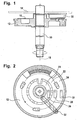
- Figure 1 is a sectional view of a contact disk in a first embodiment of a rotary position sensor;
- Figure 2 is a plan view of the contact disk;
- Figure 3 is a perspective view of a stationary contact arrangement in a second embodiment of a rotary position sensor;
- Figure 4 is an exploded view of the arrangement in Fig. 3; and
- Figure 5 is a sectional view of the rotary position sensor;
- Figure 6 is a plan view of a contact plate for incorporation into a contact disk;
- Figure 7 is a perspective view of a contact carrier disk with two sets of integrally molded scraper fingers in a further embodiment; and
- Figure 8 is a sectional view of the sensor according to the further embodiment.
- With reference to Fig. 1, an
output shaft 10 of a vehicular wiper drive carries adrive wheel 12 which is part of a reduction gear of the wiper drive (not shown).Output shaft 10 anddrive wheel 12 are accommodated within a gear box of which only acover 14 is shown in Figure 1. Acontact disk 16 is assembled withdrive wheel 12 for joint rotation about theaxis 18 ofoutput shaft 10. Thecontact disk 16 is mounted on the face ofdrive wheel 12opposite cover 14. - As seen in Fig. 2,
contact disk 16 is provided with a plurality of concentriccircular contact tracks contact track stationary contact member members contact tracks - Although not seen in the drawings, the
contact tracks scraper blade 32 extends substantially radially acrosscontact tracks Scraper blade 32 is also attached tocover 14. By the provision ofscraper blade 32, the thickness of the contact grease layer on the contact tracks is reduced to that of a film. Accordingly, thecontact members corresponding contact track scraper blade 32, an amount of contact grease will accumulate. The accumulated amount of contact grease on the upstream side ofscraper blade 32 constitutes a reserve to compensate for any loss of contact grease that might occur over the life of the wiper drive. - The arrangement shown in Figures 1 and 2 constitutes a rotary position sensor for detecting particular rotational positions of the
drive wheel 12. One of the rotational positions ofdrive wheel 12 that needs to be detected is the wiper parking position. In order to generate the appropriate sensor signals, theouter contact tracks inner contact track 20 is a continuous conductive ring. The conductive areas of allcontact tracks - In the embodiment shown in Figs. 3, 4 and 5, a gear box (not shown) has a
top cover 114 with concentric rib structures molded on the internal surface facingcontact disk 116. Specifically, as seen in Figs. 3 and 4, fourconcentric ribs Ribs base member 150 with fourscraper fingers contact members Scraper fingers 152 to 158 extend from the bottoms of partial ribs formed withbase member 150 and aligned with corresponding ones of theribs 140 to 146.Scraper fingers 152 to 158 are also generally aligned withribs 140 to 146 in the circumferential direction, but are slightly shifted radially outwardly. As seen in Fig. 4, the set ofcontact members 160 to 166 has acommon contact holder 170 accommodated in a corresponding recess ofcover 114, and thebase member 150 is also matingly accommodated in a corresponding recess ofcover 114. - With reference to Fig. 5,
contact disk 116 on itsside facing cover 114 has a groove structure generally complementary to the rib structure ofcover 114. Each of theribs 140 to 146 extends into a corresponding groove on the opposite face ofcontact disk 116, except for the circumferential area occupied byscraper fingers 152 to 158, by the partial ribs ofbase member 150 and by thecontact members 160 to 166. In this area, thescraper fingers 152 to 158 and thecontact members 160 to 166 extend into the grooves ofcontact disk 116. The free ends ofscraper fingers 152 to 158 are resiliently engaged with the bottom surfaces of corresponding grooves ofcontact disk 116, and thecontact members 160 to 166 are also slidingly and resiliently engaged with the bottom surfaces of corresponding grooves ofcontact disk 116. - Contact
disk 116 is formed by a punched or stampedmetallic contact plate 170 over-molded with an insulating plastic material. An example ofcontact plate 170 is shown in Fig. 6.Contact plate 170 has a continuous annularcentral hub 170a, a number ofarcuate recesses arms hub portion 170a has a central engagement opening 170g with a clip structure for attachment to drivewheel 112.Contact plate 170 has multiple radial streaks circumferentially spaced from each other by just a few degrees. The purpose of these radial streaks is to break any filament that could possibly be created by some sharp edge scraping over the contact surface. - As in the first embodiment, a thin layer of contact grease is provided over the contact tracks formed by
contact plate 170.Scraper fingers 152 to 158 ensure that the thickness of the contact grease layer is reduced to that of a film. Since each contact track is located at the bottom of a groove and the associated contact member and scraper finger are also located in the same groove, each sensor contact pair is independent from all other contact pairs and the inter-engaging rib and wall structures of thecontact disk 116 and of thecover 114 constitute an efficient bar against radial movement of any material, including contact grease and possible metallic filaments, so that reliable contact breaking and making functions are always ensured. - In a further embodiment, as shown in Figs. 7 and 8, a generally
circular carrier disk 200 is integrally molded from plastics with two sets of scraper fingers, 202 and 204, aligned on a diametrical line. Acontact carrier block 206 is also integrally molded with thecarrier disk 200. - With reference to Fig. 8, a
contact disk 210 similar tocontact disk 116 in the former embodiment is mounted ondrive wheel 212 for joint rotation but with a limited axial movement. Apressure spring 214 is mounted betweendrive wheel 212 andcontact disk 210 to urge contact disk againstcarrier disk 200. Other arrangements are similar to the former embodiment.
Claims (21)
- A rotary position sensor associated with a contact disk driven in rotation about an axis, in particular for a vehicular wiper drive, comprising a set of electrically conductive contact tracks extending concentrically about said axis on at least one face of said contact disk and a set of contact members held stationary opposite said contact disk face in sliding engagement with said contact tracks, characterized in that said contact tracks are covered with a thin layer of contact grease, and a scraper member is slidingly engaged with said contact tracks.
- The rotary position sensor of claim 1, wherein said scraper member is a scraper blade extending substantially radially across said contact tracks.
- The rotary position sensor of claim 1, wherein said contact disk face is provided with a plurality of concentric circular grooves and the contact tracks are located at the bottoms of said grooves, and in that a scraper finger is resiliently engaged in each groove.
- The rotary position sensor of claim 3, wherein said grooves are defined by circular ribs.
- The rotary position sensor according to claims 3 and 4, wherein said contact members and said scraper fingers are arranged on a carrier wall facing said contact disk, and the carrier wall has a plurality of concentric ribs substantially complementary in cross-sectional shape with the grooves of said contact disk, the concentric ribs and the grooves of the contact disk being inter-engaged without contacting each other.
- The rotary position sensor of claim 5, wherein said grooves and ribs have substantially rectangular cross-sections.
- The rotary position sensor of claim 5 or claim 6, wherein said scraper fingers are aligned with said ribs on the carrier wall.
- The rotary position sensor of claim 7, wherein said scraper fingers are integrally molded with a common base member that fits in a recessed sector of the concentric ribs on the carrier wall.
- The rotary position sensor of claim 8, wherein partial ribs are also integrally molded with the base member, each partial rib with an associated scraper finger substantially filling a peripheral gap in said recessed sector.
- The rotary position sensor of claim 9, wherein said partial ribs are slightly radially shifted with respect to associated scraper fingers.
- The rotary position sensor according to any of claims 5 to 10, wherein said carrier wall is formed on a top cover.
- The rotary position sensor according to any of claims 5 to 10, wherein said carrier wall is formed by a contact carrier disk.
- The rotary position sensor of claim 12, wherein the contact carrier disk has tow sets of integrally molded scraper fingers.
- The rotary position sensor of claim 13, wherein the sets of scraper fingers are aligned on a diametrical line of the carrier disk.
- The rotary position sensor according to any of claims 1 to 14, wherein said contact disk is formed of a punched metal plate over-molded with a plastics material.
- The rotary position sensor of claim 15, wherein said punched metal plate has a contact surface with multiple radial chip breaker streaks therein.
- The rotary position sensor of claim 16, wherein said contact disk has a surface structure with multiple chip catcher asperities.
- The rotary position sensor according to any of claims 1 to 17, wherein said contact disk is assembled with a drive wheel and locked with the drive wheel for joint rotation.
- The rotary position sensor according to claims 15 and 18, wherein said metal plate is shaped with a central clip structure for attachment on a drive wheel.
- The rotary position sensor according to any of claims 1 to 19, wherein said contact disk is assembled with a drive wheel and locked with the drive wheel for joint rotation.
- The rotary position sensor of claim 20, wherein the contact disk is assembled with the drive wheel for a limited axial movement and a pressure spring is mounted between the drive wheel and the contact disk.
Priority Applications (1)
| Application Number | Priority Date | Filing Date | Title |
|---|---|---|---|
| EP03291444A EP1489386A1 (en) | 2003-06-16 | 2003-06-16 | Rotary position sensor |
Applications Claiming Priority (1)
| Application Number | Priority Date | Filing Date | Title |
|---|---|---|---|
| EP03291444A EP1489386A1 (en) | 2003-06-16 | 2003-06-16 | Rotary position sensor |
Publications (1)
| Publication Number | Publication Date |
|---|---|
| EP1489386A1 true EP1489386A1 (en) | 2004-12-22 |
Family
ID=33396028
Family Applications (1)
| Application Number | Title | Priority Date | Filing Date |
|---|---|---|---|
| EP03291444A Withdrawn EP1489386A1 (en) | 2003-06-16 | 2003-06-16 | Rotary position sensor |
Country Status (1)
| Country | Link |
|---|---|
| EP (1) | EP1489386A1 (en) |
Citations (3)
| Publication number | Priority date | Publication date | Assignee | Title |
|---|---|---|---|---|
| EP0417442A2 (en) * | 1989-09-14 | 1991-03-20 | Robert Bosch Gmbh | Potentiometer which determines the position of a mobile element |
| EP0814488A1 (en) * | 1996-06-21 | 1997-12-29 | Robert Bosch Gmbh | Position sensor |
| US6064011A (en) * | 1997-10-10 | 2000-05-16 | Emerson Electric Co. | Appliance timer having an auxiliary switching assembly for increasing switching capacity and associated method |
-
2003
- 2003-06-16 EP EP03291444A patent/EP1489386A1/en not_active Withdrawn
Patent Citations (3)
| Publication number | Priority date | Publication date | Assignee | Title |
|---|---|---|---|---|
| EP0417442A2 (en) * | 1989-09-14 | 1991-03-20 | Robert Bosch Gmbh | Potentiometer which determines the position of a mobile element |
| EP0814488A1 (en) * | 1996-06-21 | 1997-12-29 | Robert Bosch Gmbh | Position sensor |
| US6064011A (en) * | 1997-10-10 | 2000-05-16 | Emerson Electric Co. | Appliance timer having an auxiliary switching assembly for increasing switching capacity and associated method |
Similar Documents
| Publication | Publication Date | Title |
|---|---|---|
| CN109638587B (en) | Axial grounding ring and discharge body for an axial grounding ring | |
| US12531460B2 (en) | Contacting device for transmitting electric currents, and machines comprising such a contacting device | |
| EP0206487B1 (en) | Disc brake assembly having an electrical lining wear indicator | |
| CA2273141C (en) | Rolling-contact bearing with current bridge | |
| CA2190356A1 (en) | Improved multi-speed motor | |
| JPH0215059Y2 (en) | ||
| JPH09182381A (en) | Flat commutator and manufacturing of the same | |
| WO2015086096A1 (en) | Sealing arrangement and electrical machine with such a sealing arrangement | |
| EP1489386A1 (en) | Rotary position sensor | |
| MXPA06009568A (en) | Snap in abs exciter ring. | |
| US11611184B2 (en) | Slip ring assembly | |
| EP0419023A1 (en) | Brake wear indicating device | |
| US11158988B2 (en) | Brush assembly | |
| US4705978A (en) | Brushgear for miniature motors | |
| MXPA03000868A (en) | Planar commutator segement attachment method and assembly. | |
| EP2562890B1 (en) | Electric motor driven liquid pump and brush for same | |
| US20030167858A1 (en) | Rotary sensor of simple construction for detecting angle of rotation transmitted from outside | |
| JP3692677B2 (en) | Ball screw seal | |
| US20260058516A1 (en) | Shaft grounding assembly | |
| EP0510736A1 (en) | Brake wear indicating device | |
| EP4188752B1 (en) | Clockspring with rolling contacts | |
| JP3573812B2 (en) | Brush holder in electric motor | |
| US20170334567A1 (en) | Propeller assembly having a brush block assembly | |
| EP2822154A2 (en) | Brush plate and electrical motor mounted with the same | |
| US20250087954A1 (en) | Shaft current collector and shaft assembly |
Legal Events
| Date | Code | Title | Description |
|---|---|---|---|
| PUAI | Public reference made under article 153(3) epc to a published international application that has entered the european phase |
Free format text: ORIGINAL CODE: 0009012 |
|
| 17P | Request for examination filed |
Effective date: 20030620 |
|
| AK | Designated contracting states |
Kind code of ref document: A1 Designated state(s): AT BE BG CH CY CZ DE DK EE ES FI FR GB GR HU IE IT LI LU MC NL PT RO SE SI SK TR |
|
| AX | Request for extension of the european patent |
Extension state: AL LT LV MK |
|
| AKX | Designation fees paid |
Designated state(s): AT BE BG CH CY CZ DE DK EE ES FI FR GB GR HU IE IT LI LU MC NL PT RO SE SI SK TR |
|
| STAA | Information on the status of an ep patent application or granted ep patent |
Free format text: STATUS: THE APPLICATION IS DEEMED TO BE WITHDRAWN |
|
| 18D | Application deemed to be withdrawn |
Effective date: 20050623 |