EP1489383B1 - Method of representing road intersections - Google Patents
Method of representing road intersections Download PDFInfo
- Publication number
- EP1489383B1 EP1489383B1 EP03257191A EP03257191A EP1489383B1 EP 1489383 B1 EP1489383 B1 EP 1489383B1 EP 03257191 A EP03257191 A EP 03257191A EP 03257191 A EP03257191 A EP 03257191A EP 1489383 B1 EP1489383 B1 EP 1489383B1
- Authority
- EP
- European Patent Office
- Prior art keywords
- intersection
- lane
- geometry
- data
- vehicle
- Prior art date
- Legal status (The legal status is an assumption and is not a legal conclusion. Google has not performed a legal analysis and makes no representation as to the accuracy of the status listed.)
- Expired - Lifetime
Links
Images




Classifications
-
- G—PHYSICS
- G01—MEASURING; TESTING
- G01C—MEASURING DISTANCES, LEVELS OR BEARINGS; SURVEYING; NAVIGATION; GYROSCOPIC INSTRUMENTS; PHOTOGRAMMETRY OR VIDEOGRAMMETRY
- G01C21/00—Navigation; Navigational instruments not provided for in groups G01C1/00 - G01C19/00
- G01C21/26—Navigation; Navigational instruments not provided for in groups G01C1/00 - G01C19/00 specially adapted for navigation in a road network
- G01C21/34—Route searching; Route guidance
- G01C21/36—Input/output arrangements for on-board computers
- G01C21/3667—Display of a road map
- G01C21/367—Details, e.g. road map scale, orientation, zooming, illumination, level of detail, scrolling of road map or positioning of current position marker
-
- G—PHYSICS
- G16—INFORMATION AND COMMUNICATION TECHNOLOGY [ICT] SPECIALLY ADAPTED FOR SPECIFIC APPLICATION FIELDS
- G16Z—INFORMATION AND COMMUNICATION TECHNOLOGY [ICT] SPECIALLY ADAPTED FOR SPECIFIC APPLICATION FIELDS, NOT OTHERWISE PROVIDED FOR
- G16Z99/00—Subject matter not provided for in other main groups of this subclass
-
- B—PERFORMING OPERATIONS; TRANSPORTING
- B60—VEHICLES IN GENERAL
- B60T—VEHICLE BRAKE CONTROL SYSTEMS OR PARTS THEREOF; BRAKE CONTROL SYSTEMS OR PARTS THEREOF, IN GENERAL; ARRANGEMENT OF BRAKING ELEMENTS ON VEHICLES IN GENERAL; PORTABLE DEVICES FOR PREVENTING UNWANTED MOVEMENT OF VEHICLES; VEHICLE MODIFICATIONS TO FACILITATE COOLING OF BRAKES
- B60T8/00—Arrangements for adjusting wheel-braking force to meet varying vehicular or ground-surface conditions, e.g. limiting or varying distribution of braking force
- B60T8/17—Using electrical or electronic regulation means to control braking
-
- G—PHYSICS
- G01—MEASURING; TESTING
- G01C—MEASURING DISTANCES, LEVELS OR BEARINGS; SURVEYING; NAVIGATION; GYROSCOPIC INSTRUMENTS; PHOTOGRAMMETRY OR VIDEOGRAMMETRY
- G01C21/00—Navigation; Navigational instruments not provided for in groups G01C1/00 - G01C19/00
- G01C21/26—Navigation; Navigational instruments not provided for in groups G01C1/00 - G01C19/00 specially adapted for navigation in a road network
-
- G—PHYSICS
- G06—COMPUTING OR CALCULATING; COUNTING
- G06F—ELECTRIC DIGITAL DATA PROCESSING
- G06F16/00—Information retrieval; Database structures therefor; File system structures therefor
- G06F16/50—Information retrieval; Database structures therefor; File system structures therefor of still image data
-
- G—PHYSICS
- G06—COMPUTING OR CALCULATING; COUNTING
- G06F—ELECTRIC DIGITAL DATA PROCESSING
- G06F16/00—Information retrieval; Database structures therefor; File system structures therefor
- G06F16/50—Information retrieval; Database structures therefor; File system structures therefor of still image data
- G06F16/51—Indexing; Data structures therefor; Storage structures
-
- G—PHYSICS
- G06—COMPUTING OR CALCULATING; COUNTING
- G06F—ELECTRIC DIGITAL DATA PROCESSING
- G06F17/00—Digital computing or data processing equipment or methods, specially adapted for specific functions
-
- Y—GENERAL TAGGING OF NEW TECHNOLOGICAL DEVELOPMENTS; GENERAL TAGGING OF CROSS-SECTIONAL TECHNOLOGIES SPANNING OVER SEVERAL SECTIONS OF THE IPC; TECHNICAL SUBJECTS COVERED BY FORMER USPC CROSS-REFERENCE ART COLLECTIONS [XRACs] AND DIGESTS
- Y02—TECHNOLOGIES OR APPLICATIONS FOR MITIGATION OR ADAPTATION AGAINST CLIMATE CHANGE
- Y02T—CLIMATE CHANGE MITIGATION TECHNOLOGIES RELATED TO TRANSPORTATION
- Y02T10/00—Road transport of goods or passengers
- Y02T10/80—Technologies aiming to reduce greenhouse gasses emissions common to all road transportation technologies
- Y02T10/82—Elements for improving aerodynamics
Definitions
- the present invention relates to methods for representing roads as data in a database, and more particularly, the present invention relates to methods for representing road intersections in a database used for vehicle driver assistance or safety systems.
- Vehicle driver assistance systems such as systems for obstacle warning and avoidance, lane departure warning, collision warning and avoidance, adaptive cruise control, adaptive transmission operation, automatic headlight aiming, and so on, have been developed to improve the safety and convenience of vehicle operation.
- These systems include technologies that augment a driver's ability to operate a vehicle safely and efficiently.
- Some of these systems include equipment that senses features around the vehicle.
- some of these systems use data that models the road network upon which the vehicle is traveling. Based on the sensed features and the model of the road network, the driver assistance and safety systems may provide warnings or otherwise modify operation of the vehicle to improve safety or convenience.
- Data representations of the road network have also been used for various other purposes.
- data representations of the road network are used in vehicle navigation systems to provide navigation-related features, such as route calculation, route guidance, map display and destination selection.
- each road segment is represented by one or more data records or entities. Associated with each data record or entity are attributes that describe various features of the represented road segment.
- Some of the features of a road segment that are represented by such data records include the location of the road segment, the locations of road intersections, the name of the road segment, the speed limit (or speed category) along the road segment, the number of lanes along the road segment, any highway designations of the road segment, the type of road surface (e.g., paved, unpaved, gravel), the presence of any lane dividers, etc.
- the ways that roads are represented in databases used in navigation systems are useful.
- the ways that roads are represented in databases used for navigation purposes may not be suitable for driver assistance and safety systems.
- the exact path that a vehicle takes across an intersection is not necessarily important.
- driver assistance systems such as obstacle avoidance or warning systems
- the paths that vehicles take through intersections may be needed to provide a warning or take another action.
- a navigation system providing lane guidance at intersections is known from e.g. US 2002/0013659 A1 .
- a database includes intersection object data entities that represent physical road intersections.
- Each intersection object data entity includes a maneuver list that identifies each permissible transversal of the intersection from each lane by which the represented intersection can be entered to each lane from which the intersection can be exited from the associated lane by which the intersection can be entered.
- Each transversal in the maneuver list indicates an entry lane, an exit lane, the geometry of a vehicle path connecting the entry and exit lanes, and an indication of a level of confidence associated with the specified geometry.
- the database can be used by a system in a vehicle to provide a safety-related function.
- the database may be compatible with navigation-related applications that use a different data model to provide navigation-related functions.
- a first embodiment relates to a method for representing road intersections in a database that contains data that represent a road network in a geographic region.
- the database is used by a system in a vehicle that provides safety or convenience features to the vehicle driver.
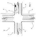
- Figure 1 shows an exemplary intersection 10 located in a geographic region.
- the intersection 10 is a location at which two roads meet at the same level.
- a first road 14 is comprised of segments 18 and 22.
- a second road 26 is comprised of segments 30 and 34. These roads 14 and 26 each have two lanes in each direction.
- Each segment also has a left turn lane (e.g., 36). The left turn lanes do not extend along the lengths of the segments. Instead, each left turn lane extends only part of the way along a segment.
- the intersection and roads shown in Figure 1 are representative of many similar intersections and roads located in the geographic region.
- a vehicle 40 travels on one of the roads. Although only one vehicle is shown in Figure 1 , the vehicle 40 is representative of many vehicles, which are similarly equipped, that travel on the roads in the geographic region. Referring to Figure 2 , the vehicle 40 includes one or more driver assistance or safety systems 44.
- the driver assistance systems 44 are systems that make operation of the vehicle safer or more convenient.
- the driver assistance systems 44 may include an obstacle warning system, a lane departure system, an adaptive cruise control system, and/or a collision avoidance system.
- the driver assistance systems 44 may include other systems in addition to, or instead of, any of these systems.
- the driver assistance systems 44 are combinations of hardware and software components.
- the driver assistance systems 44 use sensors 48.
- Various different types of sensors may be used.
- the sensors 48 measure (or are responsive to) some property, parameter, attribute, or characteristic of the vehicle or the environment around the vehicle.
- the sensors 48 may include a radar system 48(1), a camera system 48(2), or other sensors.
- the vehicle 40 includes a positioning system 50.
- the positioning system 50 is part of the driver assistance systems 44.
- the positioning system 50 may be part of another system in the vehicle 40, such as a navigation system 51.
- the positioning system 50 may be a standalone system in the vehicle.
- the positioning system 50 is a combination of hardware and software components.
- the positioning system 50 may include a GPS or DGPS unit 50( 1 ), one or more inertial sensors 50(2), such as a gyroscope or accelerometer, differential wheel sensors, or other types of equipment.
- the driver assistance systems 44 include or use a road database 60.
- the road database 60 includes a data representation of the road network in the geographic region in which the vehicle 40 is traveling.
- the road database 60 includes data that indicate the positions of the roads, the intersections of roads, and the locations of lanes, as well as other information.
- the road database 60 is used by an application 50(3) in the positioning system 50 to determine the position of the vehicle 40 relative to the road network. More specifically, the positioning application 50(3) uses the data in the road database 60 and outputs from other positioning system components, such as the GPS unit 50(1) and sensors 50(2), to determine the position of the vehicle along a road segment represented by data in the road database 60, the position of the vehicle relative to the lanes of the represented road segment, the direction and/or bearing of the vehicle along the represented road segment, and possibly other parameters.
- the positioning application 50(3) uses the data in the road database 60 and outputs from other positioning system components, such as the GPS unit 50(1) and sensors 50(2), to determine the position of the vehicle along a road segment represented by data in the road database 60, the position of the vehicle relative to the lanes of the represented road segment, the direction and/or bearing of the vehicle along the represented road segment, and possibly other parameters.
- the driver assistance systems 44 include driver assistance applications 52.
- the driver assistance applications 52 are programs that implement the functions of the driver assistance systems 44.
- the driver assistance applications 52 receive outputs from the sensors 48.
- the driver assistance applications 52 also use data from the road database 60.
- the driver assistance applications 52 may also receive other information. Based on the data received from the sensors 48, the data obtained from the road database 60, and possibly other information, the driver assistance applications 52 evaluate whether a warning or other action should be provided.
- the driver assistance systems 44 provide the safety or convenience features via a user interface 62 of the vehicle or by controlling a vehicle mechanical system 64.
- a curve warning application may provide an audible alarm via speakers (i.e., part of the user interface 62 in the vehicle) or an obstacle avoidance application may engage the vehicle's brakes (i.e., one of the mechanical systems 64 in the vehicle).
- Figure 3 shows components of the road database 60.
- roads are represented in different ways. These different ways relate to how the road data are used. The different ways that the road data are being used affect which aspects of a road are represented.
- the road database 60 includes navigation data 80 and physical configuration data 82. (In addition to navigation data 80 and physical configuration data 82, the road database 60 may include other collections of data that represent the roads in other ways.)
- the navigation data 80 and the physical configuration data 82 are indicated as being separate collections that are related to each other.
- these different ways of representing roads may be included in a single collection of data.
- the navigation data 80 are used by navigation-related applications, such as route calculation, route guidance, destination selection, and map display.
- the navigation data 80 represent the aspects of roads that are important for these functions, such as which roads connect to each other, road names, speed limits along roads, address ranges along roads, and so on.
- the navigation data 80 include data that represent road segments 84 and data that represent nodes 86. Each discrete segment of each road is represented by a separate road segment data record.
- a road segment is a portion of a road between adjacent intersections or between a dead end and an adjacent intersection.
- a road segment may also be defined that ends at a point along a road between adjacent intersections.
- the navigation data 80 in the road database 60 may also include data records that represent aggregations of individual road segments.
- a node refers to an endpoint of a road segment.
- each road segment has two endpoints.
- Each endpoint of a road segment is represented with a node data record in the road database 60.
- the road network database 60 also includes physical configuration data 82.
- the physical configuration data 82 are used by the driver assistance systems (44 in Figure 2 ) for safety and convenient features, such as obstacle warning, curve warning, and so on.
- the physical configuration data 82 provides a representation of the road network that is different from the representation provided by the navigation data 80.
- the physical configuration data 82 represent detailed aspects of the road lanes (including lane configuration), detailed aspects of the intersections, traffic signals (and placement thereof), shoulder locations, and other detailed physical features relating to roads.
- the physical configuration data 82 models the relationships between the lanes that bring traffic into the intersection and the lanes that take traffic out. Modeling these relationships involves several considerations. For example, simply extending road lanes into an intersection area would lead to many lane-to-lane crossings that would imply connectivity between crossing lanes that may not be present in reality.
- the physical configuration data 82 in the road database 60 includes a road lane data model that has road lanes that lead up to, but not through, intersections.
- intersection model used in the physical configuration data 82 in the road database 60 is addressed.
- the representations of intersections in the physical configuration data 82 are associated with the node data that represent the same corresponding actual physical intersections in the navigation data 80. Some actual physical intersections are represented by more than one node data record in the navigation data 80. For example, an intersection between a multiple-digitized road and a single digitized road may be represented by two or more node records in the navigation data 80. In such cases, the representation of an intersection in the physical configuration data is associated with all the node records in the navigation data that represent the same intersection.
- the representation of an intersection in the physical configuration data 82 should be reliably derivable from practical source materials.
- the representation of an intersection in the physical configuration data 82 should be derivable from vehicle path data obtained from driving, overhead aerial imagery, or probe vehicle ("floating car") data.
- the physical configuration data 82 of the road database 60 includes lane data entities (or records) 90 and intersection objects 100, as well as other data entities.
- the lane data entities 90 identify each lane of each road in the geographic region.
- the lane data entity 90 includes a data entity ID that uniquely identifies the lane data record in the road database 60.
- Each lane data entity 90 identifies which road the lane is part of (e.g., by reference to a road segment ID in the navigation data 90), the location of the lane (e.g., the starting location, the ending location, and the shape of the lane between the starting location and the ending location), and what is adjacent to the lane.
- the lane data entity may include other information.
- An intersection object 100 is a data entity in the road database 60.
- the intersection object 100 does not define shape or determine a position. Instead, the intersection object 100 defines the logical associations between the other data entities that represent the various physical components of the actual intersection.
- An intersection object 100 is defined for each road-to-road intersection represented in the road database 60.
- each intersection object 100 is identified by a unique ID, (e.g., an intersection object ID 100(1)).
- Each intersection objection 100 is logically associated with (i.e., references) one or more of the nodes (by node ID) that represent the intersection in the navigation data 80. Accordingly, each intersection objection 100 includes a reference 100(2) to one or more node IDs. By referencing the node IDs that represent the intersection in the navigation data 80, the intersection object 100 associates the representation of the physical configuration of the road with the navigation representation of the road network.
- Each intersection object 100 includes an attribute 100(3) that identifies the intersection type.
- the intersection type attribute 100(3) identifies the represented intersection as "standard,” “roundabout,” or “railroad crossing.” Most represented intersections are "standard.”
- An intersection like the one in Figure 1 i.e., intersection 10
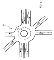
- An intersection like the one in Figure 5 i.e., intersection 102
- An intersection like the one in Figure 6 i.e., intersection 104) would be represented as a "railroad crossing” intersection. Intersections labeled as "roundabout” or "railroad crossing” are discussed below.
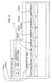
- the intersection object 100 includes a maneuver list 100(4).
- the maneuver list 100(4) includes entries for all the reasonable, legal transversals from a lane entering the represented intersection to a lane leaving the represented intersection.
- the maneuvers from three of the lanes 110, 112 and 114 entering the intersection 10 are shown.
- the lane 110 that enters the intersection 10 has one maneuver 120 onto the lane 122 and another maneuver 124 onto the lane 126.
- the lane 112 that enters the intersection 10 has only one maneuver 128, i.e., onto the lane 130.
- the lane 114 that enters the intersection 10 has one maneuver 132 onto the lane 134.
- Figure 7 illustrates the maneuvers from only the three lanes 110, 112, and 114 that enter the intersection 10 from the road segment 22. It is understood that the intersection object that represents the intersection 10 would include all the maneuvers from all the lanes from all the rest of the road segments that enter the intersection.)
- Each entry in the maneuver list 100(4) includes several kinds of data about the represented transversal.
- an entry in the maneuver list identifies the entry lane 100(4)(1) and the exit lane 100(4)(3) for the maneuver.
- the entry lane and the exit lane are identified by lane data entity IDs.
- the entry in the maneuver list 100(4) also indicates the segment of which the entry lane is a part 100(4)(2) and the segment of which the exit lane is a part 100(4)(4).
- these segments are identified by road segment IDs (i.e., references to the road segment records in the navigation data 80).
- An entry in the maneuver list 100(4) also identifies the geometry 100(4)(5) of the maneuver.
- the geometry is identified as a straight line between the end of the incoming lane 100(4)(1) and the start of the outgoing lane 100(4)(3). If the entry and exit lanes physically meet (such as in the intersection 136 illustrated in Figure 8 ), the geometry 100(4)(5) indicates the single point where the entry end exit lanes physically meet. If the travel path of a vehicle between the entry lane and the exit lane is curved, this geometry 100(4)(5) may indicate this path by defining a parametric curve.
- An entry in the maneuver list 100(4) also includes a confidence indication 100(4)(6).
- the confidence indication 100(4)(6) relates to the maneuver's geometry 100(4)(5).
- the confidence indication 100(4)(6) indicates the likelihood that the geometry of the maneuver accurately predicts or represents a vehicle path. For example, it is possible that a basic straight-line connection between and entry lane and an exit lane is highly indicative of actual vehicle paths, such as when going straight through an intersection. It is also possible that even for a turning maneuver, the vehicle path is highly predictable and well known. However, it is also possible that the vehicle path geometry through a maneuver is variable or even unknown.
- Figure 9 shows several possible paths, labeled 140, 142 and 144, that a vehicle could legally take when traveling from the left turn lane 114 on the road segment 22 onto the lane 134 on the road segment 34.
- Each of these several possible paths is a legal path.
- the entry for this transversal in the maneuver list 100(4) in the intersection object 100 that represents this intersection would include the geometry for only one of these paths.
- the maneuver entry for this transversal would have a low confidence indication 100(4)(6), i.e., meaning that the probability of the vehicle actually being on the path indicated by the geometry 100(4)(5) is relatively low.
- This confidence indication 100(4)(6) is used by driver assistance applications (52 in Figure 2 ) to determine if a vehicle's deviation from the maneuver geometry is of concern.
- the confidence indication 100(4)(6) is set to one of several values. These values include the following:
- An entry in the maneuver list 100(4) also includes an indication 100(4)(7) whether the maneuver is the "most likely path" for traffic coming from the associated incoming lane. This indication is meaningful when two or more maneuvers are possible from the same lane. This will help a driver assistance application (52 in Figure 2 ) determine a likely lane-level position.
- An entry in the maneuver list 100(4) also includes an indication 100(4)(8) whether traffic signals are present at the intersection and an indication as to which particular signal(s) govern traffic for this maneuver. It is possible that all maneuvers for a particular incoming lane will share the same signals, but it is also possible that maneuvers for different incoming lanes will be governed by different traffic signals.
- intersection object may include additional data.
- an intersection objection 100 includes an attribute that indicates an intersection type.
- One of the intersection types is "roundabout.”
- An example of a roundabout (also sometimes referred to as a traffic circle) is shown in Figure 5 .
- Having information that indicates that an intersection is a roundabout is useful for driver assistance applications that involve sensing the path ahead of a vehicle.
- a vehicle enters a roundabout intersection it follows a circular path in a single rotational direction around a center island of the roundabout.
- the vehicle entering a roundabout from an entry lane may actually travel in a direction away from the exit lane as it travels around the roundabout.
- a driver assistance application that senses the path ahead of the vehicle uses the information that an intersection is a roundabout to account for the vehicle path traveling around the roundabout.
- FIG. 6 shows an example of a "railroad crossing" intersection. Note that an intersection indicated to be a "railroad crossing” is not necessarily an intersection of actual roads. However, in a present embodiment, railroad crossings are represented by intersection objects, in part because of the presence of metal rails that may be detected by in-vehicle sensors.
- a railroad crossing is similar to a road crossing, in that the lanes may not be well defined through the crossing.
- a railroad crossing may present radar targets (not only trains but also metal rails), and may have marked stopping positions.
- a vehicle that has a driver assistance system uses a road database that has road physical configuration data to provide safety or convenience features.
- a position of the vehicle relative to the road network is determined. This function is performed by a positioning system in the vehicle.
- the driver assistance applications can predict the path ahead of a vehicle as the vehicle travels through intersections. This allows the driver assistance systems to provide safety and convenience features as the vehicle crosses an intersection.
Landscapes
- Engineering & Computer Science (AREA)
- Theoretical Computer Science (AREA)
- Physics & Mathematics (AREA)
- General Physics & Mathematics (AREA)
- Remote Sensing (AREA)
- Radar, Positioning & Navigation (AREA)
- General Engineering & Computer Science (AREA)
- Databases & Information Systems (AREA)
- Data Mining & Analysis (AREA)
- Software Systems (AREA)
- Automation & Control Theory (AREA)
- Mathematical Physics (AREA)
- Mechanical Engineering (AREA)
- Transportation (AREA)
- Traffic Control Systems (AREA)
- Navigation (AREA)
- Control Of Driving Devices And Active Controlling Of Vehicle (AREA)
- Instructional Devices (AREA)
- Processing Or Creating Images (AREA)
- Preparation Of Compounds By Using Micro-Organisms (AREA)
- Transition And Organic Metals Composition Catalysts For Addition Polymerization (AREA)
- Crystals, And After-Treatments Of Crystals (AREA)
Abstract
Description
- The present invention relates to methods for representing roads as data in a database, and more particularly, the present invention relates to methods for representing road intersections in a database used for vehicle driver assistance or safety systems.
- Vehicle driver assistance systems, such as systems for obstacle warning and avoidance, lane departure warning, collision warning and avoidance, adaptive cruise control, adaptive transmission operation, automatic headlight aiming, and so on, have been developed to improve the safety and convenience of vehicle operation. These systems include technologies that augment a driver's ability to operate a vehicle safely and efficiently. Some of these systems include equipment that senses features around the vehicle. In addition, some of these systems use data that models the road network upon which the vehicle is traveling. Based on the sensed features and the model of the road network, the driver assistance and safety systems may provide warnings or otherwise modify operation of the vehicle to improve safety or convenience.
- Data representations of the road network have also been used for various other purposes. For example, data representations of the road network are used in vehicle navigation systems to provide navigation-related features, such as route calculation, route guidance, map display and destination selection. In some databases used by navigation systems, each road segment is represented by one or more data records or entities. Associated with each data record or entity are attributes that describe various features of the represented road segment. Some of the features of a road segment that are represented by such data records include the location of the road segment, the locations of road intersections, the name of the road segment, the speed limit (or speed category) along the road segment, the number of lanes along the road segment, any highway designations of the road segment, the type of road surface (e.g., paved, unpaved, gravel), the presence of any lane dividers, etc.
- The ways that roads are represented in databases used in navigation systems are useful. However, the ways that roads are represented in databases used for navigation purposes may not be suitable for driver assistance and safety systems. For example, for navigation purposes, it is important to have data that indicate the speed limits along roads, the names of roads, the address ranges along road segments, and how much time it might take to cross a road intersection. For navigation purposes, the exact path that a vehicle takes across an intersection is not necessarily important. However, for driver assistance systems, such as obstacle avoidance or warning systems, the paths that vehicles take through intersections may be needed to provide a warning or take another action.
- A navigation system providing lane guidance at intersections is known from e.g.
US 2002/0013659 A1 . - Accordingly, it is an objective to provide a data model for road intersections that can be used by driver assistance systems.
- It is another objective to provide a data model for road intersections that is compatible with various uses of the data.
- To address these and other objectives, the present invention includes a method and system for representing road intersections as data. A database includes intersection object data entities that represent physical road intersections. Each intersection object data entity includes a maneuver list that identifies each permissible transversal of the intersection from each lane by which the represented intersection can be entered to each lane from which the intersection can be exited from the associated lane by which the intersection can be entered. Each transversal in the maneuver list indicates an entry lane, an exit lane, the geometry of a vehicle path connecting the entry and exit lanes, and an indication of a level of confidence associated with the specified geometry. The database can be used by a system in a vehicle to provide a safety-related function. The database may be compatible with navigation-related applications that use a different data model to provide navigation-related functions.
-
-
Figure 1 is an illustration of an intersection. -
Figure 2 is a block diagram that shows components of driver assistance systems in the vehicle shown inFigure 1 . -
Figure 3 is a diagram that shows components of an embodiment of the road database ofFigure 2 . -
Figure 4 is a diagram that shows components of one of the intersection objects shown inFigure 3 . -
Figure 5 is an illustration of a roundabout type of intersection. -
Figure 6 is an illustration of a railroad crossing type of intersection. -
Figure 7 shows the intersection depicted inFigure 1 with several transversals of the intersection from some of the lanes illustrated. -
Figure 8 shows an intersection in which the transversals are instantaneous. -
Figure 9 shows the intersection depicted inFigure 1 with several valid vehicle paths for a transversal of the intersection from one lane to another, illustrating that the transversal has a low confidence rating. - A first embodiment relates to a method for representing road intersections in a database that contains data that represent a road network in a geographic region. The database is used by a system in a vehicle that provides safety or convenience features to the vehicle driver.
-
Figure 1 shows anexemplary intersection 10 located in a geographic region. Theintersection 10 is a location at which two roads meet at the same level. Afirst road 14 is comprised ofsegments second road 26 is comprised ofsegments roads Figure 1 are representative of many similar intersections and roads located in the geographic region. - A
vehicle 40 travels on one of the roads. Although only one vehicle is shown inFigure 1 , thevehicle 40 is representative of many vehicles, which are similarly equipped, that travel on the roads in the geographic region. Referring toFigure 2 , thevehicle 40 includes one or more driver assistance orsafety systems 44. Thedriver assistance systems 44 are systems that make operation of the vehicle safer or more convenient. Thedriver assistance systems 44 may include an obstacle warning system, a lane departure system, an adaptive cruise control system, and/or a collision avoidance system. Thedriver assistance systems 44 may include other systems in addition to, or instead of, any of these systems. - The
driver assistance systems 44 are combinations of hardware and software components. Thedriver assistance systems 44 usesensors 48. Various different types of sensors may be used. In general, thesensors 48 measure (or are responsive to) some property, parameter, attribute, or characteristic of the vehicle or the environment around the vehicle. For example, thesensors 48 may include a radar system 48(1), a camera system 48(2), or other sensors. - The
vehicle 40 includes apositioning system 50. In the embodiment shown inFigure 2 , thepositioning system 50 is part of thedriver assistance systems 44. Alternatively, thepositioning system 50 may be part of another system in thevehicle 40, such as anavigation system 51. According to another embodiment, thepositioning system 50 may be a standalone system in the vehicle. Thepositioning system 50 is a combination of hardware and software components. For example, thepositioning system 50 may include a GPS or DGPS unit 50( 1 ), one or more inertial sensors 50(2), such as a gyroscope or accelerometer, differential wheel sensors, or other types of equipment. - In a present embodiment, the
driver assistance systems 44 include or use aroad database 60. Theroad database 60 includes a data representation of the road network in the geographic region in which thevehicle 40 is traveling. In a present embodiment, theroad database 60 includes data that indicate the positions of the roads, the intersections of roads, and the locations of lanes, as well as other information. - The
road database 60 is used by an application 50(3) in thepositioning system 50 to determine the position of thevehicle 40 relative to the road network. More specifically, the positioning application 50(3) uses the data in theroad database 60 and outputs from other positioning system components, such as the GPS unit 50(1) and sensors 50(2), to determine the position of the vehicle along a road segment represented by data in theroad database 60, the position of the vehicle relative to the lanes of the represented road segment, the direction and/or bearing of the vehicle along the represented road segment, and possibly other parameters. - The
driver assistance systems 44 includedriver assistance applications 52. Thedriver assistance applications 52 are programs that implement the functions of thedriver assistance systems 44. Thedriver assistance applications 52 receive outputs from thesensors 48. Thedriver assistance applications 52 also use data from theroad database 60. Thedriver assistance applications 52 may also receive other information. Based on the data received from thesensors 48, the data obtained from theroad database 60, and possibly other information, thedriver assistance applications 52 evaluate whether a warning or other action should be provided. Thedriver assistance systems 44 provide the safety or convenience features via auser interface 62 of the vehicle or by controlling a vehiclemechanical system 64. For example, a curve warning application may provide an audible alarm via speakers (i.e., part of theuser interface 62 in the vehicle) or an obstacle avoidance application may engage the vehicle's brakes (i.e., one of themechanical systems 64 in the vehicle). -
Figure 3 shows components of theroad database 60. In the embodiment shown inFigure 3 , roads are represented in different ways. These different ways relate to how the road data are used. The different ways that the road data are being used affect which aspects of a road are represented. For example, inFigure 3 , theroad database 60 includesnavigation data 80 and physical configuration data 82. (In addition tonavigation data 80 and physical configuration data 82, theroad database 60 may include other collections of data that represent the roads in other ways.) InFigure 3 , thenavigation data 80 and the physical configuration data 82 are indicated as being separate collections that are related to each other. However, in alternative embodiments, these different ways of representing roads may be included in a single collection of data. - The
navigation data 80 are used by navigation-related applications, such as route calculation, route guidance, destination selection, and map display. Thenavigation data 80 represent the aspects of roads that are important for these functions, such as which roads connect to each other, road names, speed limits along roads, address ranges along roads, and so on. - In the embodiment of
Figure 3 , thenavigation data 80 include data that representroad segments 84 and data that representnodes 86. Each discrete segment of each road is represented by a separate road segment data record. A road segment is a portion of a road between adjacent intersections or between a dead end and an adjacent intersection. A road segment may also be defined that ends at a point along a road between adjacent intersections. Thenavigation data 80 in theroad database 60 may also include data records that represent aggregations of individual road segments. - A node refers to an endpoint of a road segment. For example, each road segment has two endpoints. Each endpoint of a road segment is represented with a node data record in the
road database 60. - As mentioned above, the
road network database 60 also includes physical configuration data 82. The physical configuration data 82 are used by the driver assistance systems (44 inFigure 2 ) for safety and convenient features, such as obstacle warning, curve warning, and so on. - The physical configuration data 82 provides a representation of the road network that is different from the representation provided by the
navigation data 80. For example, the physical configuration data 82 represent detailed aspects of the road lanes (including lane configuration), detailed aspects of the intersections, traffic signals (and placement thereof), shoulder locations, and other detailed physical features relating to roads. Where roads intersect, the physical configuration data 82 models the relationships between the lanes that bring traffic into the intersection and the lanes that take traffic out. Modeling these relationships involves several considerations. For example, simply extending road lanes into an intersection area would lead to many lane-to-lane crossings that would imply connectivity between crossing lanes that may not be present in reality. In addition, if connectivity between lanes does exist, a simple extension of the lanes into the intersection area might indicate the point of the connectivity in the wrong place. For these reasons, as well as for other reasons, the physical configuration data 82 in theroad database 60 includes a road lane data model that has road lanes that lead up to, but not through, intersections. - The following considerations are addressed by the intersection model used in the physical configuration data 82 in the road database 60:
- (1) The road-to-road maneuvers that take place at an intersection, between specific lanes on the incoming and outgoing lanes, are described. In particular, a driver assistance application in a vehicle heading into and through an intersection is provided with the information needed to predict a likely vehicle location at some time or distance offset from the current vehicle position.
- (2) The fact that some maneuvers through an intersection have predictable vehicle paths, whereas other maneuvers through the intersection do not have a predictable path, is accommodated.
- (3) The interaction between traffic signals and traffic at the intersection is modeled. This modeling accounts for the case in which some traffic lanes or maneuvers are controlled by different aspects of the traffic signals (e.g., a left-turn signal). This modeling also accounts for the case in which some maneuvers at an intersections are governed by traffic signals and other maneuvers at the same intersection are not (e.g., a "Yield" on a right turn).
- (4) Normal intersections are distinguished from special types of intersections such as roundabouts and railroad crossings that pose special considerations for driver assistance systems.
- To support compatibility with navigation-related applications, the representations of intersections in the physical configuration data 82 are associated with the node data that represent the same corresponding actual physical intersections in the
navigation data 80. Some actual physical intersections are represented by more than one node data record in thenavigation data 80. For example, an intersection between a multiple-digitized road and a single digitized road may be represented by two or more node records in thenavigation data 80. In such cases, the representation of an intersection in the physical configuration data is associated with all the node records in the navigation data that represent the same intersection. - Another consideration associated with the representation of an intersection in the physical configuration data 82 is that the representation should be reliably derivable from practical source materials. For example, the representation of an intersection in the physical configuration data 82 should be derivable from vehicle path data obtained from driving, overhead aerial imagery, or probe vehicle ("floating car") data.
- The above considerations are addressed in an embodiment of the physical configuration data disclosed herein. Referring again to
Figure 3 , the physical configuration data 82 of theroad database 60 includes lane data entities (or records) 90 and intersection objects 100, as well as other data entities. - The
lane data entities 90 identify each lane of each road in the geographic region. Thelane data entity 90 includes a data entity ID that uniquely identifies the lane data record in theroad database 60. Eachlane data entity 90 identifies which road the lane is part of (e.g., by reference to a road segment ID in the navigation data 90), the location of the lane (e.g., the starting location, the ending location, and the shape of the lane between the starting location and the ending location), and what is adjacent to the lane. The lane data entity may include other information. - An
intersection object 100 is a data entity in theroad database 60. In a present embodiment, theintersection object 100 does not define shape or determine a position. Instead, theintersection object 100 defines the logical associations between the other data entities that represent the various physical components of the actual intersection. Anintersection object 100 is defined for each road-to-road intersection represented in theroad database 60. - Referring to
Figure 4 , eachintersection object 100 is identified by a unique ID, (e.g., an intersection object ID 100(1)). - Each
intersection objection 100 is logically associated with (i.e., references) one or more of the nodes (by node ID) that represent the intersection in thenavigation data 80. Accordingly, eachintersection objection 100 includes a reference 100(2) to one or more node IDs. By referencing the node IDs that represent the intersection in thenavigation data 80, theintersection object 100 associates the representation of the physical configuration of the road with the navigation representation of the road network. - Each
intersection object 100 includes an attribute 100(3) that identifies the intersection type. The intersection type attribute 100(3) identifies the represented intersection as "standard," "roundabout," or "railroad crossing." Most represented intersections are "standard." An intersection like the one inFigure 1 (i.e., intersection 10) would be represented as a "standard" intersection. An intersection like the one inFigure 5 (i.e., intersection 102) would be represented as a "roundabout" intersection. An intersection like the one inFigure 6 (i.e., intersection 104) would be represented as a "railroad crossing" intersection. Intersections labeled as "roundabout" or "railroad crossing" are discussed below. - Referring to
Figure 4 , theintersection object 100 includes a maneuver list 100(4). The maneuver list 100(4) includes entries for all the reasonable, legal transversals from a lane entering the represented intersection to a lane leaving the represented intersection. For example, referring toFigure 7 , the maneuvers from three of thelanes intersection 10 are shown. Thelane 110 that enters theintersection 10 has onemaneuver 120 onto thelane 122 and anothermaneuver 124 onto thelane 126. Thelane 112 that enters theintersection 10 has only onemaneuver 128, i.e., onto thelane 130. Likewise, thelane 114 that enters theintersection 10 has onemaneuver 132 onto thelane 134. (For the sake of clarity,Figure 7 illustrates the maneuvers from only the threelanes intersection 10 from theroad segment 22. It is understood that the intersection object that represents theintersection 10 would include all the maneuvers from all the lanes from all the rest of the road segments that enter the intersection.) - Each entry in the maneuver list 100(4) includes several kinds of data about the represented transversal. Referring again to
Figure 4 , an entry in the maneuver list identifies the entry lane 100(4)(1) and the exit lane 100(4)(3) for the maneuver. The entry lane and the exit lane are identified by lane data entity IDs. In the embodiment ofFigure 4 , the entry in the maneuver list 100(4) also indicates the segment of which the entry lane is a part 100(4)(2) and the segment of which the exit lane is a part 100(4)(4). In this embodiment, these segments are identified by road segment IDs (i.e., references to the road segment records in the navigation data 80). - An entry in the maneuver list 100(4) also identifies the geometry 100(4)(5) of the maneuver. At a minimum, the geometry is identified as a straight line between the end of the incoming lane 100(4)(1) and the start of the outgoing lane 100(4)(3). If the entry and exit lanes physically meet (such as in the
intersection 136 illustrated inFigure 8 ), the geometry 100(4)(5) indicates the single point where the entry end exit lanes physically meet. If the travel path of a vehicle between the entry lane and the exit lane is curved, this geometry 100(4)(5) may indicate this path by defining a parametric curve. - An entry in the maneuver list 100(4) also includes a confidence indication 100(4)(6). The confidence indication 100(4)(6) relates to the maneuver's geometry 100(4)(5). The confidence indication 100(4)(6) indicates the likelihood that the geometry of the maneuver accurately predicts or represents a vehicle path. For example, it is possible that a basic straight-line connection between and entry lane and an exit lane is highly indicative of actual vehicle paths, such as when going straight through an intersection. It is also possible that even for a turning maneuver, the vehicle path is highly predictable and well known. However, it is also possible that the vehicle path geometry through a maneuver is variable or even unknown.
-
Figure 9 shows several possible paths, labeled 140, 142 and 144, that a vehicle could legally take when traveling from theleft turn lane 114 on theroad segment 22 onto thelane 134 on theroad segment 34. Each of these several possible paths is a legal path. The entry for this transversal in the maneuver list 100(4) in theintersection object 100 that represents this intersection would include the geometry for only one of these paths. In addition, the maneuver entry for this transversal would have a low confidence indication 100(4)(6), i.e., meaning that the probability of the vehicle actually being on the path indicated by the geometry 100(4)(5) is relatively low. This confidence indication 100(4)(6) is used by driver assistance applications (52 inFigure 2 ) to determine if a vehicle's deviation from the maneuver geometry is of concern. - In a present embodiment, the confidence indication 100(4)(6) is set to one of several values. These values include the following:
- (1) None - When the confidence indication 100(4)(6) is set to "None", the geometry 100(4)(5) is set to indicate a straight-line connection. However, this straight line geometry is not intended to represent an actual vehicle path.
- (2) Instantaneous - When the confidence indication 100(4)(6) is set to "instantaneous", the incoming and outgoing lanes meet with no gap or cross-traffic. An example of an intersection with no gap between the incoming and outgoing lanes and therefore an instantaneous confidence indication, is shown in
Figure 8 . - (3) Actual, high confidence - The confidence indication 100(4)(6) is set to "Actual, high confidence" when the geometry is based on accurate sources such as probe vehicle data with small statistical variance.
- (4) Actual, variable - The confidence indication 100(4)(6) is set to "Actual, variable" when the geometry is based on sources that indicate a higher statistical variance.
- (5) Cartooned, high confidence - The confidence indication 100(4)(6) is set to "Cartooned, high confidence" when the geometry is typically, a straight-line connection for a straight-through maneuver between lanes that line up well.
- (6) Cartooned, medium confidence - The confidence indication 100(4)(6) is set to "Cartooned, medium confidence" when the geometry is digitized from tire artifacts or other evidence that does not provide a statistical variance.
- (7) Cartooned, low confidence - The confidence indication 100(4)(6) is set to "Cartooned, low confidence" when the geometry is digitized logically but without supporting evidence.
- An entry in the maneuver list 100(4) also includes an indication 100(4)(7) whether the maneuver is the "most likely path" for traffic coming from the associated incoming lane. This indication is meaningful when two or more maneuvers are possible from the same lane. This will help a driver assistance application (52 in
Figure 2 ) determine a likely lane-level position. - An entry in the maneuver list 100(4) also includes an indication 100(4)(8) whether traffic signals are present at the intersection and an indication as to which particular signal(s) govern traffic for this maneuver. It is possible that all maneuvers for a particular incoming lane will share the same signals, but it is also possible that maneuvers for different incoming lanes will be governed by different traffic signals.
- In addition to the information indicated above, the intersection object may include additional data.
- As mentioned above, an
intersection objection 100 includes an attribute that indicates an intersection type. One of the intersection types is "roundabout." An example of a roundabout (also sometimes referred to as a traffic circle) is shown inFigure 5 . Having information that indicates that an intersection is a roundabout is useful for driver assistance applications that involve sensing the path ahead of a vehicle. When a vehicle enters a roundabout intersection, it follows a circular path in a single rotational direction around a center island of the roundabout. Thus, the vehicle entering a roundabout from an entry lane may actually travel in a direction away from the exit lane as it travels around the roundabout. A driver assistance application that senses the path ahead of the vehicle uses the information that an intersection is a roundabout to account for the vehicle path traveling around the roundabout. - As mentioned above, another type of intersection is a "railroad crossing."
Figure 6 shows an example of a "railroad crossing" intersection. Note that an intersection indicated to be a "railroad crossing" is not necessarily an intersection of actual roads. However, in a present embodiment, railroad crossings are represented by intersection objects, in part because of the presence of metal rails that may be detected by in-vehicle sensors. - A railroad crossing is similar to a road crossing, in that the lanes may not be well defined through the crossing. A railroad crossing may present radar targets (not only trains but also metal rails), and may have marked stopping positions.
- As mentioned above, a vehicle that has a driver assistance system uses a road database that has road physical configuration data to provide safety or convenience features. On a continuous basis, a position of the vehicle relative to the road network is determined. This function is performed by a positioning system in the vehicle. Using the data in intersection objects, the driver assistance applications can predict the path ahead of a vehicle as the vehicle travels through intersections. This allows the driver assistance systems to provide safety and convenience features as the vehicle crosses an intersection.
- It is intended that the foregoing detailed description be regarded as illustrative rather than limiting and that it is understood that the following claims are intended to define the scope of the invention.
Claims (19)
- A method for providing driver assistance, the method comprising:storing in a road database intersection object data entities that represent physical road intersections, wherein each intersection object data entity (100) includes a maneuver list (100(4)) that contains entries that identify each permissible traversal of the (100(4)(1)) intersection from each lane by which the represented intersection can be entered to each lane from which the intersection can be legally exited (100(4)(3)) from the associated lane by which the intersection can be entered, wherein each entry in the maneuver list indicates:a lane into the intersection (100(4)(1)),a lane out of the intersection (100(4)(3));a geometry indicating a vehicle path connecting the lane into the intersection and the lane out of the intersection (100(4)(5)); anddata, indicating the likelihood that the geometry accurately represents a vehicle path (100(4)(6));evaluating from the data whether a deviation of a vehicle from the geometry is of concern.
- The method of Claim 1 wherein each intersection object further comprises data that indicate an intersection type (100(3)).
- The method of Claim 2 wherein the intersection type is one of: standard, roundabout and railroad crossing.
- The method of any preceding claim wherein at least some entries in the maneuver list in the intersection object indicate whether the represented traversal is more likely than all the other traversals of the intersection from the lane that enters the represented intersection.
- The method of Claim 1 wherein the likelihood includes: high confidence and low confidence.
- The method of Claim 1 wherein the likelihood indicates when a represented transversal is instantaneous.
- The method of Claim 1 wherein the likelihood for an entry indicates one of:none, when the geometry indicates a straight-line connection, but is not intended to represent an actual vehicle path;instantaneous, when the lane into the intersection and the lane out of the intersection meet with no gap;actual, high confidence, when the geometry is based on accurate sources;actual, variable, when the geometry is based on sources that indicate a relatively high statistical variance;cartooned, high confidence, when the geometry is for a straight-through maneuver between lanes that line up well;cartooned, medium confidence, when the geometry is digitized from sources that do not provide a statistical variance; andcartooned, low confidence, when the geometry is digitized logically but without supporting evidence.
- The method of any preceding claim wherein each intersection object further comprises:a reference to at least one node data entity that represents the intersection for navigation-related purposes.
- The method of Claim 8 wherein the node data entity is used by a navigation application to provide navigation-related features.
- A vehicle driver assistance system that includes a database that models roads, the database comprising:data entities that represent lanes of road segments, including data indicating physical configuration properties of the lanes, including locations of the lanes and which roads the lanes are associated with; andintersection object data entities (100) that represent physical configuration properties of intersections, wherein each intersection object data entity includes a maneuver list (100(4)) that identifies each permissible traversal of a represented intersection from each lane by which the represented intersection can be entered (100(4)(1)) to each lane from which the intersection can be exited (100(4)(3)) from the associated lane by which the intersection can be entered, wherein each entry in the maneuver list indicates:a lane into the intersection (100(4)(1));a lane out of the intersection (100(4)(3));a geometry indicaing a vehicle path connecting the lane into the intersection and the lane out of the intersection (100(4)(5)); anddata, indicating the likelihood that the geometry accurately represents a vehicle path (100(4)(6)), wherein the vehicle driver assistance system is arranged to use the likelihood to evaluate whether a deviation of a vehicle from the geometry is of concern.
- The system of Claim 10, wherein the database comprises:data entities that represent intersections of roads for navigation-related purposes,wherein the intersection object data entities refer to those data entities that represent intersections of roads for navigation-related purposes that represent common intersections.
- The system of Claim 11, wherein the database comprises:data entities that represent road segments for navigation-related purposes.
- The system of any of Claims 10 to 12 wherein at least some intersection object data entities include data that indicate an intersection type (100(3)).
- The system of Claim 13 wherein the intersection type is one of:standard, roundabout and railroad crossing.
- The system of any of Claims 10 to 14 wherein at least some traversals from a given lane in the maneuver list in an intersection object are indicated to be more likely than others.
- The system of Claim 10 wherein the likelihood indicates when a represented traversal is instantaneous.
- The system of Claim 10 wherein the likelihood indicates one of:none, when the geometry indicates a straight-line connection, but is not intended to represent an actual vehicle path;instantaneous, when the lane into the intersection and the lane out of the intersection meet with no gap;actual, high confidence, when the geometry is based on accurate sources;actual, variable, when the geometry is based on sources that indicate a relatively high statistical variance;cartooned, high confidence, when the geometry is for a straight-through maneuver between lanes that line up well;cartooned, medium confidence, when the geometry is digitized from sources that do not provide a statistical variance; andcartooned, low confidence, when the geometry is digitized logically but without supporting evidence.
- The system of any of Claims 10 to 17 wherein said data entities that represent lanes of road segments and said intersection object data entities are stored on a computer-readable medium.
- Apparatus comprising means adapted to carry out the method steps of any of Claims 1 to 9.
Applications Claiming Priority (2)
| Application Number | Priority Date | Filing Date | Title |
|---|---|---|---|
| US465890 | 1983-02-11 | ||
| US10/465,890 US9341485B1 (en) | 2003-06-19 | 2003-06-19 | Method and apparatus for representing road intersections |
Publications (3)
| Publication Number | Publication Date |
|---|---|
| EP1489383A2 EP1489383A2 (en) | 2004-12-22 |
| EP1489383A3 EP1489383A3 (en) | 2007-07-25 |
| EP1489383B1 true EP1489383B1 (en) | 2010-01-06 |
Family
ID=33418307
Family Applications (1)
| Application Number | Title | Priority Date | Filing Date |
|---|---|---|---|
| EP03257191A Expired - Lifetime EP1489383B1 (en) | 2003-06-19 | 2003-11-14 | Method of representing road intersections |
Country Status (5)
| Country | Link |
|---|---|
| US (5) | US9341485B1 (en) |
| EP (1) | EP1489383B1 (en) |
| JP (1) | JP4769415B2 (en) |
| AT (1) | ATE454608T1 (en) |
| DE (1) | DE60330848D1 (en) |
Cited By (1)
| Publication number | Priority date | Publication date | Assignee | Title |
|---|---|---|---|---|
| US11454513B2 (en) | 2017-11-03 | 2022-09-27 | Huawei Technologies Co., Ltd. | Method and apparatus for generating road network data of intersection area |
Families Citing this family (84)
| Publication number | Priority date | Publication date | Assignee | Title |
|---|---|---|---|---|
| EP1687171A1 (en) * | 2003-11-14 | 2006-08-09 | Continental Teves AG & Co. oHG | Method for improving an adaptive cruise control system |
| JP4281559B2 (en) * | 2004-01-15 | 2009-06-17 | 株式会社デンソー | Navigation device |
| JP2005292040A (en) * | 2004-04-02 | 2005-10-20 | Matsushita Electric Ind Co Ltd | Navigation device |
| EP1593936B1 (en) * | 2004-04-30 | 2013-02-27 | Koito Manufacturing Co., Ltd | Lighting system for vehicle |
| KR101047719B1 (en) * | 2005-02-16 | 2011-07-08 | 엘지전자 주식회사 | Method and device for driving route guidance of moving object in navigation system |
| JP2006273230A (en) * | 2005-03-30 | 2006-10-12 | Aisin Aw Co Ltd | Vehicle controller and vehicle control method |
| JP4639901B2 (en) * | 2005-03-30 | 2011-02-23 | アイシン・エィ・ダブリュ株式会社 | Vehicle control apparatus and vehicle control method |
| JP5075331B2 (en) * | 2005-09-30 | 2012-11-21 | アイシン・エィ・ダブリュ株式会社 | Map database generation system |
| US8676492B2 (en) * | 2006-01-19 | 2014-03-18 | GM Global Technology Operations LLC | Map-aided vision-based lane sensing |
| DE102006019111A1 (en) * | 2006-04-25 | 2007-10-31 | Siemens Ag | Driver assistance system for use during driving of e.g. lorry, has data processing mechanism producing position data, which characterizes position of vehicle relative to traffic lane on basis of driving side data and data of mechanism |
| US7477988B2 (en) | 2006-05-16 | 2009-01-13 | Navteq North America, Llc | Dual road geometry representation for position and curvature-heading |
| US20080082259A1 (en) * | 2006-08-30 | 2008-04-03 | Agere Systems, Inc. | Automatic turn signaling device |
| JP4692448B2 (en) * | 2006-09-12 | 2011-06-01 | 株式会社デンソー | Vehicle driving support system, vehicle driving support device, and in-vehicle device |
| DE102007041703A1 (en) * | 2007-09-03 | 2009-03-05 | GM Global Technology Operations, Inc., Detroit | Motor vehicle with a navigation system and an AFL headlight system |
| US20090144030A1 (en) * | 2007-12-04 | 2009-06-04 | Tele Atlas North America, Inc. | Computer readable storage medium storing instructions for applying clothoid curve values to roadways in a geographic data information system |
| US9123241B2 (en) | 2008-03-17 | 2015-09-01 | International Business Machines Corporation | Guided video feed selection in a vehicle-to-vehicle network |
| US8345098B2 (en) * | 2008-03-17 | 2013-01-01 | International Business Machines Corporation | Displayed view modification in a vehicle-to-vehicle network |
| US9043483B2 (en) * | 2008-03-17 | 2015-05-26 | International Business Machines Corporation | View selection in a vehicle-to-vehicle network |
| US8400507B2 (en) * | 2008-03-17 | 2013-03-19 | International Business Machines Corporation | Scene selection in a vehicle-to-vehicle network |
| EP2159777A3 (en) | 2008-05-30 | 2016-05-04 | HERE Global B.V. | Data mining to identify locations of potentially hazardous conditions for vehicle operation and use thereof |
| JP2010026326A (en) * | 2008-07-22 | 2010-02-04 | Asahi Koyo Kk | Road network data generating device, vehicle guide path generating device, and method and program for them |
| JP5353097B2 (en) * | 2008-07-22 | 2013-11-27 | 朝日航洋株式会社 | Road network data generation device, intersection lane generation device, and method and program thereof |
| US20100125386A1 (en) * | 2008-10-30 | 2010-05-20 | Faroog Abdel-Kareem Ibrahim | False alarm management in das and csw system using false alarm database and map database sensor |
| CN102227610B (en) * | 2008-11-28 | 2014-11-12 | 三菱电机株式会社 | Navigation device |
| US20100169007A1 (en) * | 2008-12-30 | 2010-07-01 | Shashikumar Kaushik | Method and apparatus for navigation system for detecting and warning traffic rule violation |
| US9068849B2 (en) * | 2009-05-04 | 2015-06-30 | Tomtom North America, Inc. | Method and system for reducing shape points in a geographic data information system |
| US9377313B2 (en) * | 2009-06-16 | 2016-06-28 | Tomtom North America Inc. | Methods and systems for creating digital street network database |
| US8340894B2 (en) * | 2009-10-08 | 2012-12-25 | Honda Motor Co., Ltd. | Method of dynamic intersection mapping |
| EP2585636A4 (en) * | 2010-06-22 | 2016-07-27 | Transoft Solutions Inc | Method and apparatus for generating a geometric layout of a traffic intersection |
| US8897948B2 (en) * | 2010-09-27 | 2014-11-25 | Toyota | Systems and methods for estimating local traffic flow |
| US8571722B2 (en) * | 2010-10-22 | 2013-10-29 | Toyota Motor Engineering & Manufacturing North America, Inc. | Method for safely parking vehicle near obstacles |
| US8452771B2 (en) * | 2011-01-03 | 2013-05-28 | Honda Motor Co., Ltd. | Method for differentiating traffic data obtained from probe vehicles |
| US8810598B2 (en) | 2011-04-08 | 2014-08-19 | Nant Holdings Ip, Llc | Interference based augmented reality hosting platforms |
| KR101074638B1 (en) * | 2011-05-04 | 2011-10-18 | 한국항공우주연구원 | Driving Lane Decision Method Using Steering Model |
| JP5708449B2 (en) * | 2011-11-08 | 2015-04-30 | アイシン・エィ・ダブリュ株式会社 | Lane guidance display system, method and program |
| JP2015501984A (en) | 2011-11-21 | 2015-01-19 | ナント ホールディングス アイピー,エルエルシー | Subscription bill service, system and method |
| EP2653833B1 (en) * | 2012-04-19 | 2018-07-25 | Elektrobit Automotive GmbH | Technique for generating from point data geometric data that continuously describe a course of a geographic object |
| WO2014003820A1 (en) * | 2012-06-29 | 2014-01-03 | Mapquest, Inc. | Systems and methods for location-based advertising |
| EP2959266A4 (en) * | 2013-02-25 | 2017-05-03 | Continental Automotive GmbH | Intelligent video navigation for automobiles |
| US9261601B2 (en) * | 2013-06-01 | 2016-02-16 | Savari, Inc. | System and method for lane boundary estimation and host vehicle position and orientation |
| US9243925B2 (en) * | 2013-08-27 | 2016-01-26 | Google Inc. | Generating a sequence of lane-specific driving directions |
| US9582516B2 (en) | 2013-10-17 | 2017-02-28 | Nant Holdings Ip, Llc | Wide area augmented reality location-based services |
| US9002646B1 (en) | 2014-02-14 | 2015-04-07 | Telenav, Inc. | Navigation system with connection simplification mechanism and method of operation thereof |
| US20150316387A1 (en) | 2014-04-30 | 2015-11-05 | Toyota Motor Engineering & Manufacturing North America, Inc. | Detailed map format for autonomous driving |
| US20150316386A1 (en) * | 2014-04-30 | 2015-11-05 | Toyota Motor Engineering & Manufacturing North America, Inc. | Detailed map format for autonomous driving |
| US9409570B2 (en) * | 2014-05-09 | 2016-08-09 | Toyota Motor Engineering & Manufacturing North America, Inc. | Method and apparatus for predicting most probable path of vehicle travel and vehicle control loss preview |
| US9830517B2 (en) * | 2014-06-19 | 2017-11-28 | Toyota Motor Engineering & Manufacturing North America, Inc. | Road branch detection and path selection for lane centering |
| EP2960129A1 (en) | 2014-06-26 | 2015-12-30 | Volvo Car Corporation | Confidence level determination for estimated road geometries |
| KR102123844B1 (en) * | 2014-07-18 | 2020-06-18 | 팅크웨어(주) | Electronic apparatus, control method of electronic apparatus and computer readable recording medium |
| US9470536B2 (en) | 2014-08-08 | 2016-10-18 | Here Global B.V. | Apparatus and associated methods for navigation of road intersections |
| US10533863B2 (en) * | 2014-10-10 | 2020-01-14 | Here Global B.V. | Apparatus and associated methods for use in lane-level mapping of road intersections |
| US10538325B1 (en) * | 2014-11-11 | 2020-01-21 | United Services Automobile Association | Utilizing unmanned vehicles to initiate and/or facilitate claims processing |
| EP3023906B1 (en) * | 2014-11-18 | 2018-05-16 | Volvo Car Corporation | Roundabout detecting arrangement, adaptive cruise control arrangement equipped therewith and method of detecting a roundabout |
| JP5971369B2 (en) * | 2015-03-11 | 2016-08-17 | 日本電気株式会社 | Driving support device, driving support method, and program |
| JP6429219B2 (en) * | 2015-08-19 | 2018-11-28 | 本田技研工業株式会社 | Vehicle control device, vehicle control method, and vehicle control program |
| US9694813B2 (en) * | 2015-08-25 | 2017-07-04 | Toyota Motor Engineering & Manufacturing North America, Inc. | Autonomous vehicle operation within a center turn lane |
| US10234294B2 (en) * | 2016-04-01 | 2019-03-19 | Here Global B.V. | Road geometry matching with componentized junction models |
| US10247559B2 (en) | 2016-05-02 | 2019-04-02 | Here Global B.V. | Method and apparatus for disambiguating probe points within an ambiguous probe region |
| US10764713B2 (en) * | 2016-05-11 | 2020-09-01 | Here Global B.V. | Map based feedback loop for vehicle observation |
| WO2018075040A1 (en) * | 2016-10-20 | 2018-04-26 | Ford Motor Company | Methods and apparatus for presenting lane and vehicle type-specific traffic information on a map |
| CN108664016B (en) * | 2017-03-31 | 2020-09-15 | 腾讯科技(深圳)有限公司 | Method and device for determining lane center line |
| JP7027738B2 (en) * | 2017-09-06 | 2022-03-02 | 株式会社デンソー | Driving support device |
| US10809728B2 (en) | 2017-09-15 | 2020-10-20 | Here Global B.V. | Lane-centric road network model for navigation |
| US11555706B1 (en) * | 2017-09-27 | 2023-01-17 | Apple Inc. | Processing graph representations of tactical maps using neural networks |
| DE102017123842A1 (en) | 2017-10-13 | 2019-04-18 | Connaught Electronics Ltd. | Lane detection method |
| JP2019105684A (en) * | 2017-12-11 | 2019-06-27 | 株式会社デンソー | Running orbit data generation device in intersection, running orbit data generation program in intersection, and storage medium |
| JP6629897B2 (en) * | 2018-02-26 | 2020-01-15 | 本田技研工業株式会社 | Vehicle control device |
| US10752249B2 (en) * | 2018-03-14 | 2020-08-25 | Toyota Research Institute, Inc. | Vehicle systems and methods for providing turn assistance at an intersection |
| CN108961758B (en) * | 2018-08-03 | 2021-02-02 | 东华理工大学 | Road junction widening lane detection method based on gradient lifting decision tree |
| US10800409B2 (en) * | 2018-09-04 | 2020-10-13 | Caterpillar Paving Products Inc. | Systems and methods for operating a mobile machine using detected sounds |
| US10747230B2 (en) * | 2018-10-08 | 2020-08-18 | Mando Corporation | Vehicle control apparatus, vehicle control system, and image sensor |
| CN111238497B (en) | 2018-11-29 | 2022-05-06 | 华为技术有限公司 | A method and device for constructing a high-precision map |
| CN111750878B (en) * | 2019-03-28 | 2022-06-24 | 北京魔门塔科技有限公司 | Vehicle pose correction method and device |
| US11200431B2 (en) | 2019-05-14 | 2021-12-14 | Here Global B.V. | Method and apparatus for providing lane connectivity data for an intersection |
| CN112991815B (en) * | 2019-12-02 | 2022-02-25 | 上海汽车集团股份有限公司 | Obstacle avoidance safety distance calculation method and device |
| CN111177927A (en) * | 2019-12-31 | 2020-05-19 | 武汉中海庭数据技术有限公司 | Vehicle reference driving line construction method, electronic device and storage medium |
| WO2021174445A1 (en) * | 2020-03-04 | 2021-09-10 | 华为技术有限公司 | Method and device for predicting exit for vehicle |
| CN111717221B (en) * | 2020-05-29 | 2022-11-11 | 重庆大学 | Automatic driving takeover risk assessment and man-machine friendly early warning method and early warning system |
| CN111578948B (en) * | 2020-06-12 | 2022-04-05 | 弗徕威智能机器人科技(上海)有限公司 | Lane adding method and system |
| CN113188550B (en) * | 2021-05-17 | 2021-12-07 | 紫清智行科技(北京)有限公司 | Map management and path planning method and system for tracking automatic driving vehicle |
| CN113593238B (en) * | 2021-08-06 | 2022-09-23 | 吉林大学 | Intersection virtual lane modeling method for automatic driving navigation |
| CN114093170B (en) * | 2021-11-26 | 2023-01-24 | 阿波罗智联(北京)科技有限公司 | Generation method, system and device of annunciator control scheme and electronic equipment |
| CN114863702B (en) * | 2022-03-28 | 2023-06-23 | 合肥学院 | A variable lane configuration method for the intersection of elevated expressway and multiple roads on the ground |
| US20250209823A1 (en) * | 2023-12-22 | 2025-06-26 | Southwest Research Institute | Homography Generation for Traffic Monitoring System |
Family Cites Families (113)
| Publication number | Priority date | Publication date | Assignee | Title |
|---|---|---|---|---|
| US4907160A (en) | 1986-01-09 | 1990-03-06 | Econolite Control Products, Inc. | Intersection monitor |
| WO1993009509A1 (en) * | 1991-11-01 | 1993-05-13 | Motorola, Inc. | An improved accuracy sensory system for vehicle navigation |
| EP0576641A1 (en) * | 1991-12-23 | 1994-01-05 | Motorola, Inc. | Vehicle navigation apparatus |
| US6553130B1 (en) * | 1993-08-11 | 2003-04-22 | Jerome H. Lemelson | Motor vehicle warning and control system and method |
| GB9317983D0 (en) * | 1993-08-28 | 1993-10-13 | Lucas Ind Plc | A driver assistance system for a vehicle |
| US5798949A (en) * | 1995-01-13 | 1998-08-25 | Kaub; Alan Richard | Traffic safety prediction model |
| US5642093A (en) * | 1995-01-27 | 1997-06-24 | Fuji Jukogyo Kabushiki Kaisha | Warning system for vehicle |
| US6720920B2 (en) | 1997-10-22 | 2004-04-13 | Intelligent Technologies International Inc. | Method and arrangement for communicating between vehicles |
| DE69620084T2 (en) | 1995-08-25 | 2002-08-22 | Aisin Aw Co., Ltd. | Navigation system for vehicles |
| KR100224326B1 (en) | 1995-12-26 | 1999-10-15 | 모리 하루오 | Car navigation system |
| KR100269070B1 (en) * | 1996-08-30 | 2000-10-16 | 모리 하루오 | Vehicle navigation device |
| US5902350A (en) * | 1996-10-30 | 1999-05-11 | Visteon Technologies, Llc | Generating a maneuver at the intersection through a turn lane |
| US5910177A (en) * | 1996-12-09 | 1999-06-08 | Visteon Technologies, Llc | Navigating close proximity routes with a vehicle navigation system |
| JPH113499A (en) * | 1997-06-10 | 1999-01-06 | Hitachi Ltd | Mobile object management system, mobile object mounting device, base station equipment, and mobile object management method |
| US6028550A (en) * | 1997-08-08 | 2000-02-22 | Trimble Navigation Limited | Vehicle guidance system using signature zones to detect travel path |
| JP3371768B2 (en) | 1997-08-29 | 2003-01-27 | 株式会社デンソー | Vehicle traveling route guidance device and map data recording medium thereof |
| US6212472B1 (en) * | 1997-09-04 | 2001-04-03 | Visteon Technologies, Llc | Method and apparatus for displaying current vehicle position |
| US9177476B2 (en) | 1997-10-22 | 2015-11-03 | American Vehicular Sciences Llc | Method and system for guiding a person to a location |
| DE19749086C1 (en) | 1997-11-06 | 1999-08-12 | Daimler Chrysler Ag | Device for determining data indicating the course of the lane |
| JPH11184375A (en) * | 1997-12-25 | 1999-07-09 | Toyota Motor Corp | Digital map data processing device and digital map data processing method |
| US6249740B1 (en) | 1998-01-21 | 2001-06-19 | Kabushikikaisha Equos Research | Communications navigation system, and navigation base apparatus and vehicle navigation apparatus both used in the navigation system |
| JP4021027B2 (en) * | 1998-01-29 | 2007-12-12 | 富士重工業株式会社 | Travel route recognition device |
| US6611753B1 (en) * | 1998-04-17 | 2003-08-26 | Magellan Dis, Inc. | 3-dimensional intersection display for vehicle navigation system |
| JP2003521672A (en) | 1998-04-30 | 2003-07-15 | ヴィステオン・テクノロジーズ・エルエルシイ | Visually Reducible Intersection Representation Method for Vehicle Navigation |
| US6184823B1 (en) * | 1998-05-01 | 2001-02-06 | Navigation Technologies Corp. | Geographic database architecture for representation of named intersections and complex intersections and methods for formation thereof and use in a navigation application program |
| US6259989B1 (en) * | 1998-06-12 | 2001-07-10 | Mitsubishi Denki K.K. | Navigation device |
| US6356840B2 (en) * | 1998-06-12 | 2002-03-12 | Mitsubishi Denki Kabushiki Kaisha | Navigation device with a three dimensional display |
| JP2987436B1 (en) * | 1998-07-31 | 1999-12-06 | 建設省土木研究所長 | Road shape information input / storage device |
| US6107939A (en) * | 1998-11-05 | 2000-08-22 | Trimble Navigation Limited | Lane change alarm for use in a highway vehicle |
| JP2000207679A (en) * | 1999-01-19 | 2000-07-28 | Equos Research Co Ltd | Information communication equipment for traveling object |
| DE19906863A1 (en) * | 1999-02-18 | 2000-10-19 | Nokia Mobile Phones Ltd | Procedure for navigating an object |
| JP3412684B2 (en) * | 1999-03-01 | 2003-06-03 | アイシン・エィ・ダブリュ株式会社 | Navigation device and recording medium of the device |
| JP2000258179A (en) | 1999-03-12 | 2000-09-22 | Denso Corp | Car navigation system |
| US6161071A (en) * | 1999-03-12 | 2000-12-12 | Navigation Technologies Corporation | Method and system for an in-vehicle computing architecture |
| US6192312B1 (en) * | 1999-03-25 | 2001-02-20 | Navigation Technologies Corp. | Position determining program and method |
| JP3076026B1 (en) | 1999-03-30 | 2000-08-14 | 松下電器産業株式会社 | Navigation device |
| WO2000058863A1 (en) * | 1999-03-31 | 2000-10-05 | Verizon Laboratories Inc. | Techniques for performing a data query in a computer system |
| WO2001011388A1 (en) * | 1999-08-06 | 2001-02-15 | Roadrisk Technologies, Llc | Methods and apparatus for stationary object detection |
| US6347280B1 (en) * | 1999-08-23 | 2002-02-12 | Aisin Aw Co., Ltd. | Navigation system and a memory medium in which programs are stored |
| JP3092804B1 (en) | 1999-09-22 | 2000-09-25 | 富士重工業株式会社 | Driving support device for vehicles |
| JP2001093099A (en) * | 1999-09-22 | 2001-04-06 | Fuji Heavy Ind Ltd | Driving support device for vehicles |
| US6188957B1 (en) * | 1999-10-04 | 2001-02-13 | Navigation Technologies Corporation | Method and system for providing bicycle information with a navigation system |
| EP1092807A1 (en) * | 1999-10-12 | 2001-04-18 | Sanei Co., Ltd. | Method and apparatus for designing roads, and storage medium |
| US6360165B1 (en) * | 1999-10-21 | 2002-03-19 | Visteon Technologies, Llc | Method and apparatus for improving dead reckoning distance calculation in vehicle navigation system |
| US6366851B1 (en) * | 1999-10-25 | 2002-04-02 | Navigation Technologies Corp. | Method and system for automatic centerline adjustment of shape point data for a geographic database |
| JP3908423B2 (en) * | 1999-12-10 | 2007-04-25 | アルパイン株式会社 | Navigation device |
| KR100508974B1 (en) * | 1999-12-18 | 2005-08-17 | 주식회사 케이티 | System and method for generating digital map using road information |
| US6415226B1 (en) * | 1999-12-20 | 2002-07-02 | Navigation Technologies Corp. | Method and system for providing safe routes using a navigation system |
| US6405128B1 (en) * | 1999-12-20 | 2002-06-11 | Navigation Technologies Corp. | Method and system for providing an electronic horizon in an advanced driver assistance system architecture |
| DE19962735A1 (en) | 1999-12-23 | 2001-06-28 | Alstom Power Schweiz Ag Baden | Method for monitoring the creep behavior of rotating components of a compressor or turbine stage |
| AU2929201A (en) | 2000-01-05 | 2001-07-16 | Johns Hopkins University, The | Global positioning system roadside integrated precision positioning system |
| JP2001272236A (en) * | 2000-01-18 | 2001-10-05 | Nissan Motor Co Ltd | Vehicle information processing device |
| DE10103714A1 (en) | 2000-01-26 | 2001-08-16 | Daimler Chrysler Ag | Producing precise digital road maps involves representing digital road map as number of geometric shapes indexed using traditional segments and nodes |
| JP3455153B2 (en) * | 2000-02-16 | 2003-10-14 | 松下電器産業株式会社 | Lane guidance display method at intersection, navigation device thereof, and recording medium |
| ATE332552T1 (en) * | 2000-02-28 | 2006-07-15 | Veridian Engineering Inc | DEVICE AND DEVICE FOR AVOIDING ACCIDENTS AT CROSSINGS |
| JP3475142B2 (en) * | 2000-03-01 | 2003-12-08 | 三菱電機株式会社 | Map data transmission device, map data transmission method, and computer-readable recording medium recording a program for causing a computer to execute the map data transmission method |
| US6424271B2 (en) | 2000-03-03 | 2002-07-23 | Subhash Raswant | Alternating time band sequence “ATBS-2W” |
| JP3967061B2 (en) | 2000-03-28 | 2007-08-29 | アルパイン株式会社 | Navigation device |
| JP2001289654A (en) * | 2000-04-11 | 2001-10-19 | Equos Research Co Ltd | NAVIGATION DEVICE, NAVIGATION DEVICE CONTROL METHOD, AND RECORDING MEDIUM RECORDING ITS PROGRAM |
| US6411898B2 (en) * | 2000-04-24 | 2002-06-25 | Matsushita Electric Industrial Co., Ltd. | Navigation device |
| JP2001304903A (en) * | 2000-04-27 | 2001-10-31 | Denso Corp | Branch guidance device |
| US6405131B1 (en) | 2000-05-22 | 2002-06-11 | Navigation Technologies Corp. | Method and system for providing route guidance with multiple progress bars |
| JP4380026B2 (en) * | 2000-06-05 | 2009-12-09 | 株式会社デンソー | Navigation device and recording medium |
| US6253151B1 (en) * | 2000-06-23 | 2001-06-26 | Navigation Technologies Corp. | Navigation system with feature for reporting errors |
| US20020103622A1 (en) * | 2000-07-17 | 2002-08-01 | Burge John R. | Decision-aid system based on wirelessly-transmitted vehicle crash sensor information |
| US7375728B2 (en) * | 2001-10-01 | 2008-05-20 | University Of Minnesota | Virtual mirror |
| JP2002062149A (en) * | 2000-08-23 | 2002-02-28 | Matsushita Electric Ind Co Ltd | In-vehicle position calculation device |
| US6526348B1 (en) | 2000-08-25 | 2003-02-25 | Navigation Technologies Corp. | Method and system for compact representation of routes |
| US6587781B2 (en) | 2000-08-28 | 2003-07-01 | Estimotion, Inc. | Method and system for modeling and processing vehicular traffic data and information and applying thereof |
| US6819779B1 (en) * | 2000-11-22 | 2004-11-16 | Cognex Corporation | Lane detection system and apparatus |
| US6581005B2 (en) * | 2000-11-30 | 2003-06-17 | Nissan Motor Co., Ltd. | Vehicle position calculation apparatus and method |
| JP4727826B2 (en) * | 2001-02-14 | 2011-07-20 | クラリオン株式会社 | Vehicle navigation system, in-vehicle guidance information output device therefor, and recording medium |
| JP4076357B2 (en) * | 2001-03-16 | 2008-04-16 | 富士通テン株式会社 | Navigation device |
| JP3736382B2 (en) * | 2001-04-26 | 2006-01-18 | アイシン・エィ・ダブリュ株式会社 | NAVIGATION DEVICE AND IMAGE DISPLAY METHOD PROGRAM |
| US6560532B2 (en) * | 2001-05-25 | 2003-05-06 | Regents Of The University Of California, The | Method and system for electronically determining dynamic traffic information |
| EP2275962A1 (en) | 2001-06-22 | 2011-01-19 | Caliper Corporation | Traffic data management and simulation system |
| US6539300B2 (en) | 2001-07-10 | 2003-03-25 | Makor Issues And Rights Ltd. | Method for regional system wide optimal signal timing for traffic control based on wireless phone networks |
| US7552008B2 (en) * | 2001-07-18 | 2009-06-23 | Regents Of The University Of Minnesota | Populating geospatial database for onboard intelligent vehicle applications |
| US20030046133A1 (en) * | 2001-08-29 | 2003-03-06 | Morley Eric Ronald | System and method of optimizing carrier selection |
| US6507785B1 (en) * | 2001-09-21 | 2003-01-14 | General Motors Corportion | Method and system for detecting and correcting off route navigation for server based route guidance systems |
| DE10146744A1 (en) | 2001-09-22 | 2003-04-17 | Bosch Gmbh Robert | Method and system for providing lane recommendations |
| DE60121963T2 (en) * | 2001-10-15 | 2007-01-18 | Ford Global Technologies, LLC, Dearborn | Method and device for controlling a vehicle |
| US7089162B2 (en) * | 2001-11-07 | 2006-08-08 | Harman International Industries, Incorporated | Navigation map creation system |
| US6424912B1 (en) * | 2001-11-09 | 2002-07-23 | General Motors Corporation | Method for providing vehicle navigation instructions |
| US6751547B2 (en) * | 2001-11-26 | 2004-06-15 | Hrl Laboratories, Llc | Method and apparatus for estimation of forward path geometry of a vehicle based on a two-clothoid road model |
| US6671616B2 (en) * | 2001-12-07 | 2003-12-30 | General Motors Corporation | One-way road point symbol generation |
| US6873911B2 (en) * | 2002-02-01 | 2005-03-29 | Nissan Motor Co., Ltd. | Method and system for vehicle operator assistance improvement |
| JP2003248896A (en) * | 2002-02-22 | 2003-09-05 | Nissan Motor Co Ltd | Information providing apparatus and method, information presenting apparatus and method |
| DE10313057A1 (en) * | 2002-03-25 | 2003-11-06 | Aisin Aw Co | Motor vehicle navigation system has an information processing unit and computer program that serves to continuously up route node points as the route map is displaced |
| US7152022B1 (en) * | 2002-04-25 | 2006-12-19 | Rajashri Joshi | Application of the ψ-s curve to road geometry extraction and modeling |
| DE10218698A1 (en) * | 2002-04-26 | 2003-11-13 | Bosch Gmbh Robert | Driver assistance system |
| US7124027B1 (en) | 2002-07-11 | 2006-10-17 | Yazaki North America, Inc. | Vehicular collision avoidance system |
| US7082443B1 (en) | 2002-07-23 | 2006-07-25 | Navteq North America, Llc | Method and system for updating geographic databases |
| US7499949B2 (en) * | 2002-08-07 | 2009-03-03 | Navteq North America, Llc | Method and system for obtaining recurring delay data using navigation systems |
| US6836781B2 (en) * | 2002-09-16 | 2004-12-28 | Navteq North America, Llc | Method for streamlined representation of roads in a geographic database |
| US6850841B1 (en) * | 2003-05-15 | 2005-02-01 | Navtech North American, Llc | Method and system for obtaining lane data |
| JP4423114B2 (en) | 2004-06-02 | 2010-03-03 | アルパイン株式会社 | Navigation device and its intersection guidance method |
| JP4722433B2 (en) | 2004-08-25 | 2011-07-13 | アルパイン株式会社 | Car navigation system |
| WO2006035755A1 (en) | 2004-09-28 | 2006-04-06 | National University Corporation Kumamoto University | Method for displaying movable-body navigation information and device for displaying movable-body navigation information |
| KR101047719B1 (en) | 2005-02-16 | 2011-07-08 | 엘지전자 주식회사 | Method and device for driving route guidance of moving object in navigation system |
| US9459622B2 (en) * | 2007-01-12 | 2016-10-04 | Legalforce, Inc. | Driverless vehicle commerce network and community |
| JP4631750B2 (en) | 2006-03-06 | 2011-02-16 | トヨタ自動車株式会社 | Image processing system |
| US9070101B2 (en) * | 2007-01-12 | 2015-06-30 | Fatdoor, Inc. | Peer-to-peer neighborhood delivery multi-copter and method |
| JP4935145B2 (en) | 2006-03-29 | 2012-05-23 | 株式会社デンソー | Car navigation system |
| DE102007030345A1 (en) | 2007-02-28 | 2008-09-04 | Navigon Ag | Navigation device and method for the graphic output of navigation instructions |
| JP4980118B2 (en) | 2007-04-06 | 2012-07-18 | アルパイン株式会社 | Car navigation system |
| US9103671B1 (en) * | 2007-11-29 | 2015-08-11 | American Vehicular Sciences, LLC | Mapping techniques using probe vehicles |
| US20090140887A1 (en) * | 2007-11-29 | 2009-06-04 | Breed David S | Mapping Techniques Using Probe Vehicles |
| JP5569365B2 (en) | 2010-11-30 | 2014-08-13 | アイシン・エィ・ダブリュ株式会社 | Guide device, guide method, and guide program |
| CA2875332A1 (en) * | 2012-06-07 | 2013-12-12 | Zoll Medical Corporation | Systems and methods for video capture, user feedback, reporting, adaptive parameters, and remote data access in vehicle safety monitoring |
| US20150168174A1 (en) * | 2012-06-21 | 2015-06-18 | Cellepathy Ltd. | Navigation instructions |
| US9120485B1 (en) * | 2012-09-14 | 2015-09-01 | Google Inc. | Methods and systems for smooth trajectory generation for a self-driving vehicle |
| US20140210646A1 (en) * | 2012-12-28 | 2014-07-31 | Balu Subramanya | Advanced parking and intersection management system |
-
2003
- 2003-06-19 US US10/465,890 patent/US9341485B1/en not_active Expired - Lifetime
- 2003-07-16 US US10/620,732 patent/US20050004753A1/en not_active Abandoned
- 2003-11-14 AT AT03257191T patent/ATE454608T1/en not_active IP Right Cessation
- 2003-11-14 DE DE60330848T patent/DE60330848D1/en not_active Expired - Lifetime
- 2003-11-14 EP EP03257191A patent/EP1489383B1/en not_active Expired - Lifetime
- 2003-12-01 JP JP2003401718A patent/JP4769415B2/en not_active Expired - Fee Related
-
2010
- 2010-07-12 US US12/804,018 patent/US9494434B2/en not_active Expired - Fee Related
-
2015
- 2015-08-26 US US14/836,392 patent/US20150362327A1/en not_active Abandoned
-
2016
- 2016-10-20 US US15/299,079 patent/US10309796B2/en not_active Expired - Lifetime
Cited By (1)
| Publication number | Priority date | Publication date | Assignee | Title |
|---|---|---|---|---|
| US11454513B2 (en) | 2017-11-03 | 2022-09-27 | Huawei Technologies Co., Ltd. | Method and apparatus for generating road network data of intersection area |
Also Published As
| Publication number | Publication date |
|---|---|
| JP4769415B2 (en) | 2011-09-07 |
| US20100312527A1 (en) | 2010-12-09 |
| US20050004753A1 (en) | 2005-01-06 |
| US10309796B2 (en) | 2019-06-04 |
| EP1489383A3 (en) | 2007-07-25 |
| ATE454608T1 (en) | 2010-01-15 |
| US20150362327A1 (en) | 2015-12-17 |
| EP1489383A2 (en) | 2004-12-22 |
| US20170045370A1 (en) | 2017-02-16 |
| JP2005010732A (en) | 2005-01-13 |
| DE60330848D1 (en) | 2010-02-25 |
| US9494434B2 (en) | 2016-11-15 |
| US9341485B1 (en) | 2016-05-17 |
Similar Documents
| Publication | Publication Date | Title |
|---|---|---|
| US9341485B1 (en) | Method and apparatus for representing road intersections | |
| US9285237B2 (en) | Method and system for representing traffic signals in a road network database | |
| EP1498694B1 (en) | Vehicle driver assistance system | |
| US7463974B2 (en) | Systems, methods, and programs for determining whether a vehicle is on-road or off-road | |
| US6405128B1 (en) | Method and system for providing an electronic horizon in an advanced driver assistance system architecture | |
| US11231294B2 (en) | Enabling alert messages in a vehicle | |
| JP4370869B2 (en) | Map data updating method and map data updating apparatus | |
| EP1111338B1 (en) | Map data architecture for vehicle computer system | |
| US20070021912A1 (en) | Current position information management systems, methods, and programs | |
| US11186293B2 (en) | Method and system for providing assistance to a vehicle or driver thereof | |
| JP3941605B2 (en) | Car navigation system | |
| JP2009015504A (en) | Traffic restriction position detection device, traffic restriction position detection method and computer program | |
| CN112204347B (en) | Method for checking whether driving mode changeover is possible safely | |
| US12325426B2 (en) | Method and apparatus for generating personalized splines | |
| JP2007034646A (en) | Safe driving support device | |
| WO2008146951A1 (en) | Object recognition device and object recognition method, and lane determination device and lane determination method using them | |
| JP2006218950A (en) | Corner learning system | |
| CN111637898A (en) | Processing method and device for high-precision navigation electronic map | |
| JP2020035364A (en) | Reverse running determination system, reverse running determination method, and reverse running determination program | |
| Ghazali et al. | Prohibited manoeuvre in automobile navigation system development |
Legal Events
| Date | Code | Title | Description |
|---|---|---|---|
| PUAI | Public reference made under article 153(3) epc to a published international application that has entered the european phase |
Free format text: ORIGINAL CODE: 0009012 |
|
| AK | Designated contracting states |
Kind code of ref document: A2 Designated state(s): AT BE BG CH CY CZ DE DK EE ES FI FR GB GR HU IE IT LI LU MC NL PT RO SE SI SK TR |
|
| AX | Request for extension of the european patent |
Extension state: AL LT LV MK |
|
| RAP1 | Party data changed (applicant data changed or rights of an application transferred) |
Owner name: NAVTEQ NORTH AMERICA, LLC |
|
| PUAL | Search report despatched |
Free format text: ORIGINAL CODE: 0009013 |
|
| AK | Designated contracting states |
Kind code of ref document: A3 Designated state(s): AT BE BG CH CY CZ DE DK EE ES FI FR GB GR HU IE IT LI LU MC NL PT RO SE SI SK TR |
|
| AX | Request for extension of the european patent |
Extension state: AL LT LV MK |
|
| 17P | Request for examination filed |
Effective date: 20070911 |
|
| AKX | Designation fees paid |
Designated state(s): AT BE BG CH CY CZ DE DK EE ES FI FR GB GR HU IE IT LI LU MC NL PT RO SE SI SK TR |
|
| 17Q | First examination report despatched |
Effective date: 20080421 |
|
| RAP1 | Party data changed (applicant data changed or rights of an application transferred) |
Owner name: NAVTEQ NORTH AMERICA, LLC |
|
| GRAP | Despatch of communication of intention to grant a patent |
Free format text: ORIGINAL CODE: EPIDOSNIGR1 |
|
| GRAS | Grant fee paid |
Free format text: ORIGINAL CODE: EPIDOSNIGR3 |
|
| GRAA | (expected) grant |
Free format text: ORIGINAL CODE: 0009210 |
|
| AK | Designated contracting states |
Kind code of ref document: B1 Designated state(s): AT BE BG CH CY CZ DE DK EE ES FI FR GB GR HU IE IT LI LU MC NL PT RO SE SI SK TR |
|
| REG | Reference to a national code |
Ref country code: GB Ref legal event code: FG4D |
|
| REG | Reference to a national code |
Ref country code: CH Ref legal event code: EP |
|
| REG | Reference to a national code |
Ref country code: IE Ref legal event code: FG4D |
|
| REF | Corresponds to: |
Ref document number: 60330848 Country of ref document: DE Date of ref document: 20100225 Kind code of ref document: P |
|
| PG25 | Lapsed in a contracting state [announced via postgrant information from national office to epo] |
Ref country code: SI Free format text: LAPSE BECAUSE OF FAILURE TO SUBMIT A TRANSLATION OF THE DESCRIPTION OR TO PAY THE FEE WITHIN THE PRESCRIBED TIME-LIMIT Effective date: 20100106 |
|
| PG25 | Lapsed in a contracting state [announced via postgrant information from national office to epo] |
Ref country code: AT Free format text: LAPSE BECAUSE OF FAILURE TO SUBMIT A TRANSLATION OF THE DESCRIPTION OR TO PAY THE FEE WITHIN THE PRESCRIBED TIME-LIMIT Effective date: 20100106 |
|
| PG25 | Lapsed in a contracting state [announced via postgrant information from national office to epo] |
Ref country code: ES Free format text: LAPSE BECAUSE OF FAILURE TO SUBMIT A TRANSLATION OF THE DESCRIPTION OR TO PAY THE FEE WITHIN THE PRESCRIBED TIME-LIMIT Effective date: 20100417 Ref country code: PT Free format text: LAPSE BECAUSE OF FAILURE TO SUBMIT A TRANSLATION OF THE DESCRIPTION OR TO PAY THE FEE WITHIN THE PRESCRIBED TIME-LIMIT Effective date: 20100506 |
|
| PG25 | Lapsed in a contracting state [announced via postgrant information from national office to epo] |
Ref country code: FI Free format text: LAPSE BECAUSE OF FAILURE TO SUBMIT A TRANSLATION OF THE DESCRIPTION OR TO PAY THE FEE WITHIN THE PRESCRIBED TIME-LIMIT Effective date: 20100106 |
|
| PG25 | Lapsed in a contracting state [announced via postgrant information from national office to epo] |
Ref country code: SE Free format text: LAPSE BECAUSE OF FAILURE TO SUBMIT A TRANSLATION OF THE DESCRIPTION OR TO PAY THE FEE WITHIN THE PRESCRIBED TIME-LIMIT Effective date: 20100106 Ref country code: BE Free format text: LAPSE BECAUSE OF FAILURE TO SUBMIT A TRANSLATION OF THE DESCRIPTION OR TO PAY THE FEE WITHIN THE PRESCRIBED TIME-LIMIT Effective date: 20100106 Ref country code: CY Free format text: LAPSE BECAUSE OF FAILURE TO SUBMIT A TRANSLATION OF THE DESCRIPTION OR TO PAY THE FEE WITHIN THE PRESCRIBED TIME-LIMIT Effective date: 20100106 Ref country code: EE Free format text: LAPSE BECAUSE OF FAILURE TO SUBMIT A TRANSLATION OF THE DESCRIPTION OR TO PAY THE FEE WITHIN THE PRESCRIBED TIME-LIMIT Effective date: 20100106 Ref country code: GR Free format text: LAPSE BECAUSE OF FAILURE TO SUBMIT A TRANSLATION OF THE DESCRIPTION OR TO PAY THE FEE WITHIN THE PRESCRIBED TIME-LIMIT Effective date: 20100407 Ref country code: RO Free format text: LAPSE BECAUSE OF FAILURE TO SUBMIT A TRANSLATION OF THE DESCRIPTION OR TO PAY THE FEE WITHIN THE PRESCRIBED TIME-LIMIT Effective date: 20100106 |
|
| PLBE | No opposition filed within time limit |
Free format text: ORIGINAL CODE: 0009261 |
|
| STAA | Information on the status of an ep patent application or granted ep patent |
Free format text: STATUS: NO OPPOSITION FILED WITHIN TIME LIMIT |
|
| PG25 | Lapsed in a contracting state [announced via postgrant information from national office to epo] |
Ref country code: BG Free format text: LAPSE BECAUSE OF FAILURE TO SUBMIT A TRANSLATION OF THE DESCRIPTION OR TO PAY THE FEE WITHIN THE PRESCRIBED TIME-LIMIT Effective date: 20100406 Ref country code: SK Free format text: LAPSE BECAUSE OF FAILURE TO SUBMIT A TRANSLATION OF THE DESCRIPTION OR TO PAY THE FEE WITHIN THE PRESCRIBED TIME-LIMIT Effective date: 20100106 Ref country code: CZ Free format text: LAPSE BECAUSE OF FAILURE TO SUBMIT A TRANSLATION OF THE DESCRIPTION OR TO PAY THE FEE WITHIN THE PRESCRIBED TIME-LIMIT Effective date: 20100106 |
|
| 26N | No opposition filed |
Effective date: 20101007 |
|
| PG25 | Lapsed in a contracting state [announced via postgrant information from national office to epo] |
Ref country code: DK Free format text: LAPSE BECAUSE OF FAILURE TO SUBMIT A TRANSLATION OF THE DESCRIPTION OR TO PAY THE FEE WITHIN THE PRESCRIBED TIME-LIMIT Effective date: 20100106 |
|
| PG25 | Lapsed in a contracting state [announced via postgrant information from national office to epo] |
Ref country code: IT Free format text: LAPSE BECAUSE OF FAILURE TO SUBMIT A TRANSLATION OF THE DESCRIPTION OR TO PAY THE FEE WITHIN THE PRESCRIBED TIME-LIMIT Effective date: 20100106 |
|
| PG25 | Lapsed in a contracting state [announced via postgrant information from national office to epo] |
Ref country code: MC Free format text: LAPSE BECAUSE OF NON-PAYMENT OF DUE FEES Effective date: 20101130 |
|
| REG | Reference to a national code |
Ref country code: CH Ref legal event code: PL |
|
| PG25 | Lapsed in a contracting state [announced via postgrant information from national office to epo] |
Ref country code: CH Free format text: LAPSE BECAUSE OF NON-PAYMENT OF DUE FEES Effective date: 20101130 Ref country code: LI Free format text: LAPSE BECAUSE OF NON-PAYMENT OF DUE FEES Effective date: 20101130 |
|
| PG25 | Lapsed in a contracting state [announced via postgrant information from national office to epo] |
Ref country code: IE Free format text: LAPSE BECAUSE OF NON-PAYMENT OF DUE FEES Effective date: 20101114 |
|
| PG25 | Lapsed in a contracting state [announced via postgrant information from national office to epo] |
Ref country code: HU Free format text: LAPSE BECAUSE OF FAILURE TO SUBMIT A TRANSLATION OF THE DESCRIPTION OR TO PAY THE FEE WITHIN THE PRESCRIBED TIME-LIMIT Effective date: 20100707 Ref country code: LU Free format text: LAPSE BECAUSE OF NON-PAYMENT OF DUE FEES Effective date: 20101114 |
|
| PG25 | Lapsed in a contracting state [announced via postgrant information from national office to epo] |
Ref country code: TR Free format text: LAPSE BECAUSE OF FAILURE TO SUBMIT A TRANSLATION OF THE DESCRIPTION OR TO PAY THE FEE WITHIN THE PRESCRIBED TIME-LIMIT Effective date: 20100106 |
|
| REG | Reference to a national code |
Ref country code: DE Ref legal event code: R082 Ref document number: 60330848 Country of ref document: DE Representative=s name: SPLANEMANN BARONETZKY KNITTER PATENTANWAELTE R, DE Ref country code: DE Ref legal event code: R081 Ref document number: 60330848 Country of ref document: DE Owner name: HERE GLOBAL B.V., NL Free format text: FORMER OWNER: NAVTEQ NORTH AMERICA, LLC, CHICAGO, ILL., US |
|
| REG | Reference to a national code |
Ref country code: GB Ref legal event code: 732E Free format text: REGISTERED BETWEEN 20150827 AND 20150902 |
|
| REG | Reference to a national code |
Ref country code: FR Ref legal event code: PLFP Year of fee payment: 13 |
|
| REG | Reference to a national code |
Ref country code: FR Ref legal event code: CD Owner name: HERE GLOBAL B.V., NL Effective date: 20151211 Ref country code: FR Ref legal event code: TP Owner name: HERE GLOBAL B.V., NL Effective date: 20151211 |
|
| REG | Reference to a national code |
Ref country code: NL Ref legal event code: PD Owner name: HERE GLOBAL B.V.; NL Free format text: DETAILS ASSIGNMENT: VERANDERING VAN EIGENAAR(S), OVERDRACHT; FORMER OWNER NAME: HERE NORTH AMERICA, LLC Effective date: 20151006 Ref country code: NL Ref legal event code: HC Owner name: HERE NORTH AMERICA, LLC; US Free format text: DETAILS ASSIGNMENT: VERANDERING VAN EIGENAAR(S), VERANDERING VAN NAAM VAN DE EIGENAAR(S); FORMER OWNER NAME: NAVTEQ NORTH AMERICA, LLC Effective date: 20151006 |
|
| REG | Reference to a national code |
Ref country code: FR Ref legal event code: PLFP Year of fee payment: 14 |
|
| REG | Reference to a national code |
Ref country code: FR Ref legal event code: PLFP Year of fee payment: 15 |
|
| REG | Reference to a national code |
Ref country code: FR Ref legal event code: PLFP Year of fee payment: 16 |
|
| PGFP | Annual fee paid to national office [announced via postgrant information from national office to epo] |
Ref country code: NL Payment date: 20220916 Year of fee payment: 20 Ref country code: GB Payment date: 20220922 Year of fee payment: 20 |
|
| PGFP | Annual fee paid to national office [announced via postgrant information from national office to epo] |
Ref country code: FR Payment date: 20220908 Year of fee payment: 20 |
|
| PGFP | Annual fee paid to national office [announced via postgrant information from national office to epo] |
Ref country code: DE Payment date: 20220921 Year of fee payment: 20 |
|
| REG | Reference to a national code |
Ref country code: DE Ref legal event code: R071 Ref document number: 60330848 Country of ref document: DE |
|
| REG | Reference to a national code |
Ref country code: NL Ref legal event code: MK Effective date: 20231113 |
|
| REG | Reference to a national code |
Ref country code: GB Ref legal event code: PE20 Expiry date: 20231113 |
|
| PG25 | Lapsed in a contracting state [announced via postgrant information from national office to epo] |
Ref country code: GB Free format text: LAPSE BECAUSE OF EXPIRATION OF PROTECTION Effective date: 20231113 |
|
| PG25 | Lapsed in a contracting state [announced via postgrant information from national office to epo] |
Ref country code: GB Free format text: LAPSE BECAUSE OF EXPIRATION OF PROTECTION Effective date: 20231113 |