EP1489336A2 - Method of using compression springs to create a desired torsional load - Google Patents
Method of using compression springs to create a desired torsional load Download PDFInfo
- Publication number
- EP1489336A2 EP1489336A2 EP04252861A EP04252861A EP1489336A2 EP 1489336 A2 EP1489336 A2 EP 1489336A2 EP 04252861 A EP04252861 A EP 04252861A EP 04252861 A EP04252861 A EP 04252861A EP 1489336 A2 EP1489336 A2 EP 1489336A2
- Authority
- EP
- European Patent Office
- Prior art keywords
- springs
- spring
- phaser
- torsional load
- rotor
- Prior art date
- Legal status (The legal status is an assumption and is not a legal conclusion. Google has not performed a legal analysis and makes no representation as to the accuracy of the status listed.)
- Withdrawn
Links
- 238000000034 method Methods 0.000 title claims abstract description 9
- 230000006835 compression Effects 0.000 title claims description 3
- 238000007906 compression Methods 0.000 title claims description 3
- RDYMFSUJUZBWLH-UHFFFAOYSA-N endosulfan Chemical compound C12COS(=O)OCC2C2(Cl)C(Cl)=C(Cl)C1(Cl)C2(Cl)Cl RDYMFSUJUZBWLH-UHFFFAOYSA-N 0.000 claims abstract description 21
- 230000014759 maintenance of location Effects 0.000 claims abstract description 19
- 230000007246 mechanism Effects 0.000 description 8
- 230000036316 preload Effects 0.000 description 4
- 238000004088 simulation Methods 0.000 description 2
- 238000002485 combustion reaction Methods 0.000 description 1
- 230000008878 coupling Effects 0.000 description 1
- 238000010168 coupling process Methods 0.000 description 1
- 238000005859 coupling reaction Methods 0.000 description 1
- 238000013016 damping Methods 0.000 description 1
- 230000007423 decrease Effects 0.000 description 1
- 230000003247 decreasing effect Effects 0.000 description 1
- 230000010355 oscillation Effects 0.000 description 1
Images




Classifications
-
- F—MECHANICAL ENGINEERING; LIGHTING; HEATING; WEAPONS; BLASTING
- F01—MACHINES OR ENGINES IN GENERAL; ENGINE PLANTS IN GENERAL; STEAM ENGINES
- F01L—CYCLICALLY OPERATING VALVES FOR MACHINES OR ENGINES
- F01L1/00—Valve-gear or valve arrangements, e.g. lift-valve gear
- F01L1/34—Valve-gear or valve arrangements, e.g. lift-valve gear characterised by the provision of means for changing the timing of the valves without changing the duration of opening and without affecting the magnitude of the valve lift
- F01L1/344—Valve-gear or valve arrangements, e.g. lift-valve gear characterised by the provision of means for changing the timing of the valves without changing the duration of opening and without affecting the magnitude of the valve lift changing the angular relationship between crankshaft and camshaft, e.g. using helicoidal gear
-
- F—MECHANICAL ENGINEERING; LIGHTING; HEATING; WEAPONS; BLASTING
- F01—MACHINES OR ENGINES IN GENERAL; ENGINE PLANTS IN GENERAL; STEAM ENGINES
- F01L—CYCLICALLY OPERATING VALVES FOR MACHINES OR ENGINES
- F01L1/00—Valve-gear or valve arrangements, e.g. lift-valve gear
- F01L1/34—Valve-gear or valve arrangements, e.g. lift-valve gear characterised by the provision of means for changing the timing of the valves without changing the duration of opening and without affecting the magnitude of the valve lift
- F01L1/344—Valve-gear or valve arrangements, e.g. lift-valve gear characterised by the provision of means for changing the timing of the valves without changing the duration of opening and without affecting the magnitude of the valve lift changing the angular relationship between crankshaft and camshaft, e.g. using helicoidal gear
- F01L1/34409—Valve-gear or valve arrangements, e.g. lift-valve gear characterised by the provision of means for changing the timing of the valves without changing the duration of opening and without affecting the magnitude of the valve lift changing the angular relationship between crankshaft and camshaft, e.g. using helicoidal gear by torque-responsive means
-
- F—MECHANICAL ENGINEERING; LIGHTING; HEATING; WEAPONS; BLASTING
- F01—MACHINES OR ENGINES IN GENERAL; ENGINE PLANTS IN GENERAL; STEAM ENGINES
- F01L—CYCLICALLY OPERATING VALVES FOR MACHINES OR ENGINES
- F01L1/00—Valve-gear or valve arrangements, e.g. lift-valve gear
- F01L1/34—Valve-gear or valve arrangements, e.g. lift-valve gear characterised by the provision of means for changing the timing of the valves without changing the duration of opening and without affecting the magnitude of the valve lift
- F01L1/344—Valve-gear or valve arrangements, e.g. lift-valve gear characterised by the provision of means for changing the timing of the valves without changing the duration of opening and without affecting the magnitude of the valve lift changing the angular relationship between crankshaft and camshaft, e.g. using helicoidal gear
- F01L1/3442—Valve-gear or valve arrangements, e.g. lift-valve gear characterised by the provision of means for changing the timing of the valves without changing the duration of opening and without affecting the magnitude of the valve lift changing the angular relationship between crankshaft and camshaft, e.g. using helicoidal gear using hydraulic chambers with variable volume to transmit the rotating force
-
- F—MECHANICAL ENGINEERING; LIGHTING; HEATING; WEAPONS; BLASTING
- F01—MACHINES OR ENGINES IN GENERAL; ENGINE PLANTS IN GENERAL; STEAM ENGINES
- F01L—CYCLICALLY OPERATING VALVES FOR MACHINES OR ENGINES
- F01L1/00—Valve-gear or valve arrangements, e.g. lift-valve gear
- F01L1/34—Valve-gear or valve arrangements, e.g. lift-valve gear characterised by the provision of means for changing the timing of the valves without changing the duration of opening and without affecting the magnitude of the valve lift
- F01L1/344—Valve-gear or valve arrangements, e.g. lift-valve gear characterised by the provision of means for changing the timing of the valves without changing the duration of opening and without affecting the magnitude of the valve lift changing the angular relationship between crankshaft and camshaft, e.g. using helicoidal gear
- F01L1/3442—Valve-gear or valve arrangements, e.g. lift-valve gear characterised by the provision of means for changing the timing of the valves without changing the duration of opening and without affecting the magnitude of the valve lift changing the angular relationship between crankshaft and camshaft, e.g. using helicoidal gear using hydraulic chambers with variable volume to transmit the rotating force
- F01L2001/3445—Details relating to the hydraulic means for changing the angular relationship
- F01L2001/34483—Phaser return springs
-
- F—MECHANICAL ENGINEERING; LIGHTING; HEATING; WEAPONS; BLASTING
- F01—MACHINES OR ENGINES IN GENERAL; ENGINE PLANTS IN GENERAL; STEAM ENGINES
- F01L—CYCLICALLY OPERATING VALVES FOR MACHINES OR ENGINES
- F01L2820/00—Details on specific features characterising valve gear arrangements
- F01L2820/01—Absolute values
Definitions
- the invention pertains to the field of variable valve timing. More particularly, the invention pertains to a method of producing torsional stiffness between two rotating parts.
- torsional dampers have been used to reduce and absorb the vibrations of a rotating shaft preventing the transfer of the shaft vibrations to other areas of the engine system by using combinations of friction plates and torsion springs.
- US Patent No. 1,518,360 uses an annular plate and washers compressed between the inner member and the spring loaded annular member whereby oscillation is damped out and all end slack is eliminated.
- US Patent No. 6,161,512 which uses a sprocket with three circumferentially spaced stops and a hub including three spaced hub locators. Springs are attached between adjacent hub locators and rotational stops. Friction plates are also included and provide damping action, such that the sprocket only rotates slightly relative to the hub locator. The internal torsional damper of this patent is biased in two directions and the spring is not controlled.
- Other examples include US Patent Nos. 447,447, 306,267, and 1,254,542.
- the present invention provides a method of controlling the torque exerted by a mechanism containing springs.
- the present invention decreases the size of prior art torque producing mechanisms both axially and radially.
- the present invention is also easier to assemble and divides the load on the spring equally between the number of springs present increasing the life of the torque producing mechanism.
- a method of introducing torsional load into a phaser having the steps of determining the required torsional load between the rotor and housing needed to generate the desired performance in the phaser, choosing the number of springs to introduce the required torsional load based on space and design requirements of the torque generating device, and determining the spring characteristics required for the desired performance of the phaser.
- the springs are circumferentially placed in the end plate fixed to the housing having spaced block projections, and a spring retention plate fixed to the rotor having apertures for receiving the spaced block projections.
- One end of the springs are placed adjacent to tabs located on a back side of the spring retention plate and the other end of the springs are placed adjacent to the block projections of the end plate, such that motion between the rotor and housing introduces torsional load.
- phaser In a variable cam timing (VCT) system, the timing gear or sprocket on the camshaft is replaced by a variable angle coupling known as a "phaser", having a rotor connected to the camshaft and a housing connected to (or forming) the timing gear, which allows the camshaft to rotate independently of the timing gear, within angular limits, to change the relative timing of the camshaft and crankshaft.
- phaser includes the housing and the rotor, and all of the parts to control the relative angular position of the housing and rotor, to allow the timing of the camshaft to be offset from the crankshaft.
- the multiple-camshaft engine it will be understood that there could be one phaser on each camshaft, as is known to the art.
- a torsional load is commonly needed to help actuate the system or to offset an accessory torque, such as an oil pump, vacuum pump, or other such device, to bring the phaser back to base timing.
- the torsional load or stiffness is between the two rotating parts of the phaser, the rotor and the housing (not shown).
- a spring retention plate 16 fixed to the rotor and an end plate 12 fixed to the housing are mountably attached to each other. Between the spring retention plate 16 and the end plate 12 are circumferentially placed compression springs 24. In Figure 8 three springs are shown, but depending upon the size restrictions more or less springs may be used in keeping with the spirit of the invention.
- One end of the spring 24 is placed adjacent to tabs 18, (shown in Figures 4, 5b, and 7) located on the back side of the spring retention plate 16 and the other end of the spring 24 is placed adjacent to the block projections 14 (shown in Figures 1, 2a, and 2b) located on the end plate 12.
- the springs are easily preloaded.
- the block projections 14 are spaced such on the end plate that they are received by the apertures 22 in the spring retention plate 16.
- Bolt are then used to fasten the spring retention plate 16 to the end plate 12 securely.
- the secure fastening of the spring retention plate 16 to the end plate 12 also prevents bucking of the springs 24.
- a method of generating the required torsional load using the above described device requires certain steps.
- the first step is to determine the required torsional load in order to achieve the desired performance of the phaser by simulation. Based on the required torsional load and the space available, the number of springs to be used are chosen. Then, spring characteristics are determined. Examples of spring characteristics include, but are not limited to: spring rate, number of turns the spring contains, outer diameter of the spring, and wire pitch of the spring. The spring characteristics are chosen to allow the springs to compress to a specific length allowing the torque generated to be specifically controlled.
- the three springs were chosen to be placed circumferentially between the two rotating parts of the phaser and if the amount of torque that is needed to generate the desired performance of the phaser by simulation was 4 Nm (Newton meters).
- the spring's outer diameter and wire pitch are chosen such that the torque needed, 4 Nm, is easily achieved.
- the three springs placed circumferentially would have an outer diameter of 10 mm and a spring location of 80.02 mm. From the chosen springs outer diameter and spring location, the deflection at both pre-load conditions and maximum load conditions can easily be determined. In this example, the deflection of the springs at pre-load conditions is 29 Nm and 45 Nm at maximum load conditions.
- the deflection of the springs at pre-load conditions corresponds to 1.2 Nm torque for each spring and 1.8 Nm torque at maximum load conditions. Since the springs act in parallel, sharing the load equally among the springs present, the total torque exerted by the three springs is 3.6 Nm at pre-load conditions and 5.4 Nm at maximum load conditions, meeting the necessary torque requirement for the desired performance of the phaser.
- the force and therefore the torque generated by the springs may easily be controlled, while decreasing the size of the device both axially and radially, making the device easy to assemble and increasing the life of the torque producing mechanism.
Landscapes
- Engineering & Computer Science (AREA)
- Mechanical Engineering (AREA)
- General Engineering & Computer Science (AREA)
- Mechanical Operated Clutches (AREA)
- Valve Device For Special Equipments (AREA)
Abstract
Description
- The invention pertains to the field of variable valve timing. More particularly, the invention pertains to a method of producing torsional stiffness between two rotating parts.
- In some internal combustion engines, torsional dampers have been used to reduce and absorb the vibrations of a rotating shaft preventing the transfer of the shaft vibrations to other areas of the engine system by using combinations of friction plates and torsion springs. For example US Patent No. 1,518,360 uses an annular plate and washers compressed between the inner member and the spring loaded annular member whereby oscillation is damped out and all end slack is eliminated.
- Another example of a damper is shown in US Patent No. 1,165,529 in which parts of a spring sprocket wheel are provided with radial arms or projections that extend beyond the circle of the sprocket teeth and have a spring connection between the outer portion of the projecting portion beyond the sprocket teeth.
- Another example is US Patent No. 6,161,512, which uses a sprocket with three circumferentially spaced stops and a hub including three spaced hub locators. Springs are attached between adjacent hub locators and rotational stops. Friction plates are also included and provide damping action, such that the sprocket only rotates slightly relative to the hub locator. The internal torsional damper of this patent is biased in two directions and the spring is not controlled. Other examples include US Patent Nos. 447,447, 306,267, and 1,254,542.
- The present invention provides a method of controlling the torque exerted by a mechanism containing springs. The present invention decreases the size of prior art torque producing mechanisms both axially and radially. The present invention is also easier to assemble and divides the load on the spring equally between the number of springs present increasing the life of the torque producing mechanism.
- A method of introducing torsional load into a phaser, having the steps of determining the required torsional load between the rotor and housing needed to generate the desired performance in the phaser, choosing the number of springs to introduce the required torsional load based on space and design requirements of the torque generating device, and determining the spring characteristics required for the desired performance of the phaser. The springs are circumferentially placed in the end plate fixed to the housing having spaced block projections, and a spring retention plate fixed to the rotor having apertures for receiving the spaced block projections. One end of the springs are placed adjacent to tabs located on a back side of the spring retention plate and the other end of the springs are placed adjacent to the block projections of the end plate, such that motion between the rotor and housing introduces torsional load.
-
- Fig. 1
- shows an isometric view of the end plate.
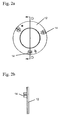
- Fig. 2a
- shows a top view of the end plate.
- Fig, 2b
- shows a sectional view of the end plate along line D-D in Figure 2a.
- Fig. 3
- shows an isometric view of the front of the spring retention plate of the torque producing mechanism.
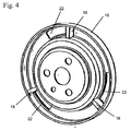
- Fig. 4
- shows an isometric view of the back of the spring retention plate of the torque producing mechanism.
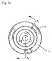
- Fig. 5a
- shows a front view of the front of the spring retention plate.
- Fig, 5b
- shows a sectional view of the spring retention plate along line A-A in Figure 5a.
- Fig. 6
- shows a front view of the back of the spring retention plate.
- Fig. 7
- shows an isometric view of tabs in the torque producing mechanism.
- Fig. 8
- shows an expanded view of the torque producing mechanism.
- In a variable cam timing (VCT) system, the timing gear or sprocket on the camshaft is replaced by a variable angle coupling known as a "phaser", having a rotor connected to the camshaft and a housing connected to (or forming) the timing gear, which allows the camshaft to rotate independently of the timing gear, within angular limits, to change the relative timing of the camshaft and crankshaft. The term "phaser", as used here, includes the housing and the rotor, and all of the parts to control the relative angular position of the housing and rotor, to allow the timing of the camshaft to be offset from the crankshaft. In the multiple-camshaft engine, it will be understood that there could be one phaser on each camshaft, as is known to the art.
- In phasers, a torsional load is commonly needed to help actuate the system or to offset an accessory torque, such as an oil pump, vacuum pump, or other such device, to bring the phaser back to base timing. The torsional load or stiffness is between the two rotating parts of the phaser, the rotor and the housing (not shown). A
spring retention plate 16 fixed to the rotor and anend plate 12 fixed to the housing are mountably attached to each other. Between thespring retention plate 16 and theend plate 12 are circumferentially placedcompression springs 24. In Figure 8 three springs are shown, but depending upon the size restrictions more or less springs may be used in keeping with the spirit of the invention. One end of thespring 24 is placed adjacent totabs 18, (shown in Figures 4, 5b, and 7) located on the back side of thespring retention plate 16 and the other end of thespring 24 is placed adjacent to the block projections 14 (shown in Figures 1, 2a, and 2b) located on theend plate 12. By placing one end of thesprings 24 to one of the rotating parts of the phaser, the rotor or the housing and the other end of thespring 24 to second rotating part of the phaser, the other rotor or housing, the springs are easily preloaded. Theblock projections 14 are spaced such on the end plate that they are received by theapertures 22 in thespring retention plate 16. Bolt are then used to fasten thespring retention plate 16 to theend plate 12 securely. The secure fastening of thespring retention plate 16 to theend plate 12 also prevents bucking of thesprings 24. - The movement of either the
end plate 12 or thespring retention plate 16 results in a torsional load between thespring retention plate 16 and theend plate 12, such that the device acts as a torsional damper to one side only. - A method of generating the required torsional load using the above described device requires certain steps. The first step is to determine the required torsional load in order to achieve the desired performance of the phaser by simulation. Based on the required torsional load and the space available, the number of springs to be used are chosen. Then, spring characteristics are determined. Examples of spring characteristics include, but are not limited to: spring rate, number of turns the spring contains, outer diameter of the spring, and wire pitch of the spring. The spring characteristics are chosen to allow the springs to compress to a specific length allowing the torque generated to be specifically controlled. For example, if due to space availability three springs were chosen to be placed circumferentially between the two rotating parts of the phaser and if the amount of torque that is needed to generate the desired performance of the phaser by simulation was 4 Nm (Newton meters). The spring's outer diameter and wire pitch are chosen such that the torque needed, 4 Nm, is easily achieved. In this instance the three springs placed circumferentially would have an outer diameter of 10 mm and a spring location of 80.02 mm. From the chosen springs outer diameter and spring location, the deflection at both pre-load conditions and maximum load conditions can easily be determined. In this example, the deflection of the springs at pre-load conditions is 29 Nm and 45 Nm at maximum load conditions. The deflection of the springs at pre-load conditions corresponds to 1.2 Nm torque for each spring and 1.8 Nm torque at maximum load conditions. Since the springs act in parallel, sharing the load equally among the springs present, the total torque exerted by the three springs is 3.6 Nm at pre-load conditions and 5.4 Nm at maximum load conditions, meeting the necessary torque requirement for the desired performance of the phaser.
- By controlling the spring characteristics in the torque producing device, the force and therefore the torque generated by the springs may easily be controlled, while decreasing the size of the device both axially and radially, making the device easy to assemble and increasing the life of the torque producing mechanism.
- Accordingly, it is to be understood that the embodiments of the invention herein described are merely illustrative of the application of the principles of the invention. Reference herein to details of the illustrated embodiments is not intended to limit the scope of the claims, which themselves recite those features regarded as essential to the invention.
Claims (3)
- A method of introducing torsional load into a phaser comprising a rotor and a housing, comprising the steps of:wherein a first end of the springs from step d) are placed adjacent to tabs located on a back side of the spring retention plate and a second end of the springs are placed adjacent to the block projections of the end plate, such that any relative motion between the rotor and the housing introduces torsional load into the phaser.a) determining required torsional load between the rotor and the housing needed to generate desired performance in the phaser;b) choosing a number of springs to introduce the required torsional load based on space and design requirements of a torque generating device;c) determining spring characteristics required for a response to result in the desired performance of the phaser;d) placing the springs from step b) circumferentially in a torque generating device comprising:i) an end plate fixed to a housing having spaced block projections, andii) a spring retention plate fixed to a rotor having apertures for receiving the spaced block projections of the end plate,
- The method of claim 1, wherein the springs are compression springs.
- The method of claim 1 or 2, wherein the spring characteristics are spring rate, spring location, the number of turns of the spring, and the outer diameter of the spring.
Applications Claiming Priority (2)
| Application Number | Priority Date | Filing Date | Title |
|---|---|---|---|
| US462330 | 2003-06-16 | ||
| US10/462,330 US20040250648A1 (en) | 2003-06-16 | 2003-06-16 | Method of using compression springs to create a desired torsional load |
Publications (2)
| Publication Number | Publication Date |
|---|---|
| EP1489336A2 true EP1489336A2 (en) | 2004-12-22 |
| EP1489336A3 EP1489336A3 (en) | 2005-01-19 |
Family
ID=33418116
Family Applications (1)
| Application Number | Title | Priority Date | Filing Date |
|---|---|---|---|
| EP04252861A Withdrawn EP1489336A3 (en) | 2003-06-16 | 2004-05-17 | Method of using compression springs to create a desired torsional load |
Country Status (3)
| Country | Link |
|---|---|
| US (1) | US20040250648A1 (en) |
| EP (1) | EP1489336A3 (en) |
| JP (1) | JP2005009489A (en) |
Cited By (2)
| Publication number | Priority date | Publication date | Assignee | Title |
|---|---|---|---|---|
| WO2012042408A1 (en) * | 2010-09-30 | 2012-04-05 | Mechadyne Plc | Cam summation engine valve system |
| CN104131853A (en) * | 2013-05-02 | 2014-11-05 | 谢夫勒科技股份两合公司 | Cam shaft adjuster |
Families Citing this family (4)
| Publication number | Priority date | Publication date | Assignee | Title |
|---|---|---|---|---|
| DE112009001743B4 (en) * | 2008-08-15 | 2018-02-15 | Borgwarner Inc. | Sprocket with damper and balancer |
| US8555836B2 (en) * | 2010-12-10 | 2013-10-15 | Delphi Technologies, Inc. | Electric drive camshaft phaser with torque rate limit at travel stops |
| KR101637752B1 (en) * | 2014-12-01 | 2016-07-20 | 현대자동차주식회사 | Torque Filter having Impact Spring Constant |
| KR20200056839A (en) * | 2018-11-15 | 2020-05-25 | 현대자동차주식회사 | Damper for engine mounted with motor |
Citations (6)
| Publication number | Priority date | Publication date | Assignee | Title |
|---|---|---|---|---|
| US306267A (en) | 1884-10-07 | Power-transmitting pulley | ||
| US447447A (en) | 1891-03-03 | Gearing | ||
| US1165529A (en) | 1913-03-10 | 1915-12-28 | Morse Chain Co | Spring sprocket-wheel for drive-chains. |
| US1254542A (en) | 1917-08-03 | 1918-01-22 | Frank W Schwinn | Compensating sprocket. |
| US1518360A (en) | 1924-05-14 | 1924-12-09 | Rolls Royce | Mounting of engine gears |
| US6161512A (en) | 1998-09-17 | 2000-12-19 | Morse Tec Europe S.P.A. | Sprocket system with internal torsional damper |
Family Cites Families (8)
| Publication number | Priority date | Publication date | Assignee | Title |
|---|---|---|---|---|
| US1254549A (en) * | 1916-04-03 | 1918-01-22 | Eugene H Taylor | Insole-trimming machine. |
| US5619887A (en) * | 1995-08-28 | 1997-04-15 | Borg-Warner Automotive, Inc. | Camshaft tuned vibration damper |
| US6142115A (en) * | 1997-09-09 | 2000-11-07 | Luk Lamellen Und Kupplungsbau, Gmbh | Vibration damper for the crankshaft of a piston engine |
| JPH11173118A (en) * | 1997-12-12 | 1999-06-29 | Toyota Motor Corp | Variable valve timing mechanism for internal combustion engine |
| KR100290299B1 (en) * | 1998-12-22 | 2001-05-15 | 이재화 | Sprocket Drive of Bicycle |
| DE19916675B4 (en) * | 1999-04-14 | 2005-07-07 | Daimlerchrysler Ag | Device for relative angular adjustment of a camshaft |
| JP3964207B2 (en) * | 2000-01-25 | 2007-08-22 | 三菱電機株式会社 | Valve timing adjustment device |
| DE60033534T2 (en) * | 2000-07-10 | 2007-11-22 | Mitsubishi Denki K.K. | TIMING DEVICE |
-
2003
- 2003-06-16 US US10/462,330 patent/US20040250648A1/en not_active Abandoned
-
2004
- 2004-05-17 JP JP2004145977A patent/JP2005009489A/en active Pending
- 2004-05-17 EP EP04252861A patent/EP1489336A3/en not_active Withdrawn
Patent Citations (6)
| Publication number | Priority date | Publication date | Assignee | Title |
|---|---|---|---|---|
| US306267A (en) | 1884-10-07 | Power-transmitting pulley | ||
| US447447A (en) | 1891-03-03 | Gearing | ||
| US1165529A (en) | 1913-03-10 | 1915-12-28 | Morse Chain Co | Spring sprocket-wheel for drive-chains. |
| US1254542A (en) | 1917-08-03 | 1918-01-22 | Frank W Schwinn | Compensating sprocket. |
| US1518360A (en) | 1924-05-14 | 1924-12-09 | Rolls Royce | Mounting of engine gears |
| US6161512A (en) | 1998-09-17 | 2000-12-19 | Morse Tec Europe S.P.A. | Sprocket system with internal torsional damper |
Cited By (2)
| Publication number | Priority date | Publication date | Assignee | Title |
|---|---|---|---|---|
| WO2012042408A1 (en) * | 2010-09-30 | 2012-04-05 | Mechadyne Plc | Cam summation engine valve system |
| CN104131853A (en) * | 2013-05-02 | 2014-11-05 | 谢夫勒科技股份两合公司 | Cam shaft adjuster |
Also Published As
| Publication number | Publication date |
|---|---|
| EP1489336A3 (en) | 2005-01-19 |
| US20040250648A1 (en) | 2004-12-16 |
| JP2005009489A (en) | 2005-01-13 |
Similar Documents
| Publication | Publication Date | Title |
|---|---|---|
| JP5496904B2 (en) | Torque converter | |
| US6234127B1 (en) | Torsionally compliant and damped sprocket system with position stops | |
| EP1726789B1 (en) | Camshaft assembly | |
| US5979390A (en) | Assembly for transmitting rotational movements and for damping torsional vibrations | |
| JP5414795B2 (en) | Sprocket with damper and compensator | |
| EP1136721B1 (en) | Balancer shaft for an internal combustion engine | |
| JP2005002992A (en) | Phase shifter | |
| US20040226393A1 (en) | Crankshaft having a damper | |
| JP2005069227A (en) | VCT system | |
| US10557385B2 (en) | Engine variable camshaft timing phaser with planetary gear assembly | |
| US7669567B2 (en) | Valve timing adjusting device | |
| EP1489336A2 (en) | Method of using compression springs to create a desired torsional load | |
| US6988601B2 (en) | Torque converter | |
| US6932037B2 (en) | Variable CAM timing (VCT) system having modifications to increase CAM torsionals for engines having limited inherent torsionals | |
| US20110061614A1 (en) | Camshaft having a tuned mass damper | |
| US20090223469A1 (en) | Balance shaft drive system | |
| US10895177B2 (en) | Timing wheel for a camshaft phaser arrangement for a concentric camshaft assembly | |
| WO2000058643A1 (en) | Flywheel | |
| JP4611970B2 (en) | Rotating device | |
| JPH09184403A (en) | Valve timing adjustment device for internal combustion engine | |
| US10612429B1 (en) | Coupling for a camshaft phaser arrangement for a concentric camshaft assembly | |
| JPS5969549A (en) | Device for restraining cam shaft vibration in internal-combustion engine | |
| CN113518853B (en) | internal combustion engine | |
| US11852054B2 (en) | Variable camshaft timing system | |
| US11940030B1 (en) | Torque-limiting torsion gimbal |
Legal Events
| Date | Code | Title | Description |
|---|---|---|---|
| PUAI | Public reference made under article 153(3) epc to a published international application that has entered the european phase |
Free format text: ORIGINAL CODE: 0009012 |
|
| PUAL | Search report despatched |
Free format text: ORIGINAL CODE: 0009013 |
|
| AK | Designated contracting states |
Kind code of ref document: A2 Designated state(s): AT BE BG CH CY CZ DE DK EE ES FI FR GB GR HU IE IT LI LU MC NL PL PT RO SE SI SK TR |
|
| AX | Request for extension of the european patent |
Extension state: AL HR LT LV MK |
|
| AK | Designated contracting states |
Kind code of ref document: A3 Designated state(s): AT BE BG CH CY CZ DE DK EE ES FI FR GB GR HU IE IT LI LU MC NL PL PT RO SE SI SK TR |
|
| AX | Request for extension of the european patent |
Extension state: AL HR LT LV MK |
|
| RIC1 | Information provided on ipc code assigned before grant |
Ipc: 7F 01L 1/344 B Ipc: 7F 16F 15/123 A |
|
| 17P | Request for examination filed |
Effective date: 20050209 |
|
| RAP1 | Party data changed (applicant data changed or rights of an application transferred) |
Owner name: BORGWARNER INC. |
|
| 17Q | First examination report despatched |
Effective date: 20050513 |
|
| AKX | Designation fees paid |
Designated state(s): DE FR IT |
|
| GRAP | Despatch of communication of intention to grant a patent |
Free format text: ORIGINAL CODE: EPIDOSNIGR1 |
|
| STAA | Information on the status of an ep patent application or granted ep patent |
Free format text: STATUS: THE APPLICATION IS DEEMED TO BE WITHDRAWN |
|
| 18D | Application deemed to be withdrawn |
Effective date: 20060627 |