EP1489319A2 - Lubrication structure for rolling bearing - Google Patents
Lubrication structure for rolling bearing Download PDFInfo
- Publication number
- EP1489319A2 EP1489319A2 EP04001990A EP04001990A EP1489319A2 EP 1489319 A2 EP1489319 A2 EP 1489319A2 EP 04001990 A EP04001990 A EP 04001990A EP 04001990 A EP04001990 A EP 04001990A EP 1489319 A2 EP1489319 A2 EP 1489319A2
- Authority
- EP
- European Patent Office
- Prior art keywords
- oil
- lubrication
- lubrication oil
- rolling bearing
- accumulating room
- Prior art date
- Legal status (The legal status is an assumption and is not a legal conclusion. Google has not performed a legal analysis and makes no representation as to the accuracy of the status listed.)
- Withdrawn
Links
Images



Classifications
-
- F—MECHANICAL ENGINEERING; LIGHTING; HEATING; WEAPONS; BLASTING
- F16—ENGINEERING ELEMENTS AND UNITS; GENERAL MEASURES FOR PRODUCING AND MAINTAINING EFFECTIVE FUNCTIONING OF MACHINES OR INSTALLATIONS; THERMAL INSULATION IN GENERAL
- F16C—SHAFTS; FLEXIBLE SHAFTS; ELEMENTS OR CRANKSHAFT MECHANISMS; ROTARY BODIES OTHER THAN GEARING ELEMENTS; BEARINGS
- F16C33/00—Parts of bearings; Special methods for making bearings or parts thereof
- F16C33/30—Parts of ball or roller bearings
- F16C33/66—Special parts or details in view of lubrication
- F16C33/6637—Special parts or details in view of lubrication with liquid lubricant
- F16C33/6659—Details of supply of the liquid to the bearing, e.g. passages or nozzles
- F16C33/6677—Details of supply of the liquid to the bearing, e.g. passages or nozzles from radial inside, e.g. via a passage through the shaft and/or inner ring
-
- F—MECHANICAL ENGINEERING; LIGHTING; HEATING; WEAPONS; BLASTING
- F16—ENGINEERING ELEMENTS AND UNITS; GENERAL MEASURES FOR PRODUCING AND MAINTAINING EFFECTIVE FUNCTIONING OF MACHINES OR INSTALLATIONS; THERMAL INSULATION IN GENERAL
- F16C—SHAFTS; FLEXIBLE SHAFTS; ELEMENTS OR CRANKSHAFT MECHANISMS; ROTARY BODIES OTHER THAN GEARING ELEMENTS; BEARINGS
- F16C33/00—Parts of bearings; Special methods for making bearings or parts thereof
- F16C33/30—Parts of ball or roller bearings
- F16C33/66—Special parts or details in view of lubrication
- F16C33/6637—Special parts or details in view of lubrication with liquid lubricant
- F16C33/664—Retaining the liquid in or near the bearing
- F16C33/6651—Retaining the liquid in or near the bearing in recesses or cavities provided in retainers, races or rolling elements
-
- F—MECHANICAL ENGINEERING; LIGHTING; HEATING; WEAPONS; BLASTING
- F16—ENGINEERING ELEMENTS AND UNITS; GENERAL MEASURES FOR PRODUCING AND MAINTAINING EFFECTIVE FUNCTIONING OF MACHINES OR INSTALLATIONS; THERMAL INSULATION IN GENERAL
- F16C—SHAFTS; FLEXIBLE SHAFTS; ELEMENTS OR CRANKSHAFT MECHANISMS; ROTARY BODIES OTHER THAN GEARING ELEMENTS; BEARINGS
- F16C19/00—Bearings with rolling contact, for exclusively rotary movement
- F16C19/02—Bearings with rolling contact, for exclusively rotary movement with bearing balls essentially of the same size in one or more circular rows
- F16C19/04—Bearings with rolling contact, for exclusively rotary movement with bearing balls essentially of the same size in one or more circular rows for radial load mainly
- F16C19/06—Bearings with rolling contact, for exclusively rotary movement with bearing balls essentially of the same size in one or more circular rows for radial load mainly with a single row or balls
-
- F—MECHANICAL ENGINEERING; LIGHTING; HEATING; WEAPONS; BLASTING
- F16—ENGINEERING ELEMENTS AND UNITS; GENERAL MEASURES FOR PRODUCING AND MAINTAINING EFFECTIVE FUNCTIONING OF MACHINES OR INSTALLATIONS; THERMAL INSULATION IN GENERAL
- F16C—SHAFTS; FLEXIBLE SHAFTS; ELEMENTS OR CRANKSHAFT MECHANISMS; ROTARY BODIES OTHER THAN GEARING ELEMENTS; BEARINGS
- F16C19/00—Bearings with rolling contact, for exclusively rotary movement
- F16C19/54—Systems consisting of a plurality of bearings with rolling friction
- F16C19/541—Systems consisting of juxtaposed rolling bearings including at least one angular contact bearing
-
- F—MECHANICAL ENGINEERING; LIGHTING; HEATING; WEAPONS; BLASTING
- F16—ENGINEERING ELEMENTS AND UNITS; GENERAL MEASURES FOR PRODUCING AND MAINTAINING EFFECTIVE FUNCTIONING OF MACHINES OR INSTALLATIONS; THERMAL INSULATION IN GENERAL
- F16C—SHAFTS; FLEXIBLE SHAFTS; ELEMENTS OR CRANKSHAFT MECHANISMS; ROTARY BODIES OTHER THAN GEARING ELEMENTS; BEARINGS
- F16C2360/00—Engines or pumps
Definitions
- the present invention relates to a lubrication structure for a rolling bearing that is used for high speed rotation.
- FIGS. 1a and 1b show conventional lubrication structures of the rolling bearing.
- FIG. 1a shows the jet injection method
- FIG. 1b shows the inner ring lubrication method.
- the rolling bearing includes an inner ring 22a, an outer ring 22b, a plurality of rolling elements 22c installed between the inner ring 22a and the outer ring 22c, retainers 22d retaining the rolling elements 22c.
- lubrication oil 21 is injected from a jet nozzle 25 toward the side of the inner ring 22a of the bearing.
- the lubrication oil 21 passes through the bearing, and is accumulated in a bearing room.
- the lubrication oil 21 in the bearing room is scavenged to the outside by an oil scavenge pump (not shown in the drawing).
- the lubrication oil 21 strikes a side surface of the retainers 22d of the bearing, and rebounds therefrom.
- the rebounding lubrication oil interferes with further supplying of the lubrication oil 21. Therefore, there is a problem in that the lubrication oil cannot be smoothly supplied to the inside of the bearing.
- a lubrication structure for the inner ring lubrication method shown in FIG. 1b includes a lubrication oil hole 23 that radially penetrates through the inner ring 22a of the bearing, and an oil accumulating room 26 of which rotational axis is positioned on a rotational axis of the rolling bearing and that accumulates the lubrication oil 21 by using a centrifugal force of the rotation of the oil accumulating room 26.
- the lubrication structure of FIG. 1b further includes a lubrication oil supplying path 24 that communicates with the oil accumulating room 26 and the lubrication oil hole 23.
- the present invention was made to solve the above-mentioned problems. It is a first object of the present invention to enhance a cooling effect of a bearing by decreasing a rotational speed difference between an oil accumulating room and lubrication oil, and thereby increasing an oil quantity actually used for the bearing lubrication. Further, it is a second object of the present invention to provide a bearing lubrication structure that makes it easy to estimate a supplying quantity of lubrication oil and that improves accuracy in prediction of the lubrication oil quantity actually used for the bearing lubrication.
- a lubrication structure for a rolling bearing comprising:
- the fin member installed in the oil accumulating room causes the lubrication oil in the oil accumulating room to follow the rotation of the oil accumulating room so that the lubrication oil can be forcibly rotated. Accordingly, a rotational speed difference between the oil accumulating room and the lubrication oil can be made small. Therefore, a centrifugal force applied on the lubrication oil can be increased, the lubrication oil quantity actually used for the bearing lubrication can be increased, and a cooling effect of the bearing can be enhanced.
- the fin member extends in a radial direction and an axial direction.
- a forcible force that causes the lubrication oil to rotate can be increased, and a difference in the number of revolutions between the oil accumulating room and the lubrication oil can be effectively reduced. Therefore, a lubrication oil quantity actually used for the bearing lubrication can be increased, and a cooling effect of the bearing can be reliably enhanced. Further, in accordance with a rotational speed of the oil accumulating room, the centrifugal force of the lubrication oil is increased, and a supplying quantity of lubrication oil can be determined. Therefore, it becomes easy to estimate a supplying quantity of lubrication oil, and it is possible to improve accuracy in prediction of lubrication oil quantity that is actually used for the bearing lubrication.
- the fin member is installed at a plurality of positions in a circumferential direction.
- the forcible force that causes the lubrication oil to rotate can be further increased, and the difference in the number of revolutions between the lubrication oil and the oil accumulating room can be further reduced. Therefore, the lubrication oil quantity actually used for the bearing lubrication can be further increased, and the cooling effect of the bearing can be further effectively improved. In addition, it is possible to further improve accuracy in prediction of the lubrication oil quantity actually used for the bearing lubrication.
- the present invention can also provide a machine that uses a rolling bearing and has the above-described lubrication structure for the rolling bearing.
- this machine is a gas-turbine engine or a supercharger.
- this machine is not limited to these machines and may be any machine to which the above-described lubrication structure can be applied.
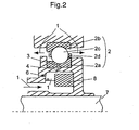
- FIG. 2 shows an embodiment of a bearing lubrication structure according to the present invention.
- the reference numeral 2 designates a rolling bearing.
- the rolling bearing 2 includes an inner ring 2a, an outer ring 2b, a plurality of balls 2c installed between the inner ring 2a and the outer ring 2b, and retainers 2d that retains the balls 2c.
- An oil accumulating room 6 that accumulates lubrication oil 1 is provided at a radial inner side of the inner ring 2a.
- the oil accumulating room 6 forms an annular space that extends in the circumferential direction around a central shaft 7.
- Lubrication oil holes 3 that radially penetrate through the inner ring 2a are respectively formed in the inner ring at a plurality positions in the circumferential direction.
- lubrication oil supplying paths 4 that communicate with the oil accumulating room 6 and the lubrication oil holes 3.
- a rolling bearing includes a ball bearing and a roller bearing
- an axial direction means an axial direction of a bearing 2, a shaft 7 or the like
- a radial direction means a radial direction of the bearing 2, the shaft 7 or the like
- the term “circumferential direction” means a circumferential direction of the bearing 2, the shaft 7 or the like.
- platy fin members 8 that extend in the axial direction and the radial direction are formed on an inner surface of the oil accumulating room 6.
- four fin members 8 are installed in the oil accumulating room 6 along the circumferential direction.
- the present invention is not limited to this embodiment, and it is preferable to appropriately determine a fixing position depending on a shape, a size, or the like of the oil accumulating room 6.
- a fixing position depending on a shape, a size, or the like of the oil accumulating room 6.
- the number of the fin members is not limited to four, a shape of the fin member is not limited to a rectangle, and the number and shape of the fin member is determined depending on the shape and size of the oil accumulating room 6.
- FIG. 3a is a sectional view showing an embodied example of the bearing lubrication structure according to the present invention.
- FIG. 3b is a cross sectional view taken along the line X-X in FIG. 3a.
- a bearing in this embodied example is applied to a supercharger for a boat, ship or vessel.
- the reference numeral 10 designates a shaft, 11 a four contact point ball bearing, 12 an angular ball bearing, 13 a cylindrical rotary cup having a cavity, and 14 a disk member.
- a space defined by the rotary cup 13, the disk member14, and a shaft end nut 30 of the shaft 10 forms an oil accumulating room 15.
- the reference numerals 16 and 17 designate lubrication oil holes that supply the lubrication oil to the inside of the bearing and radially penetrate through the inner rings 11 and 12, respectively.
- the lubrication oil holes 16 and 17 are formed at a plurality of positions in the inner rings 11 and 12 in the circumferential direction thereof.
- the reference numeral 18 designate a lubrication oil supplying path that communicates with the oil accumulating room 15 and the oil supplying holes 16 and 17. Accordingly, the lubrication oil can flow from the oil accumulating room 15 to the oil supplying holes 16 and 17 via the lubrication oil supplying path 18.
- the lubrication oil supplying path 18 includes a flow path 18a that penetrates through the disk member 14, and a flow path 18b that corresponds to the bearings 11 and 12.
- the flow path 18a is formed to incline relative to the shaft 10 such that a distance between one end opening of the flow path 18a at the side of the oil accumulating room 15 and the central axis of the shaft 10 is larger than a distance between the other end of the flow path 18a connected to the flow path 18b and the central axis of the shaft 10.
- the reference numeral 20 designates a fin member having a thickness of 0.1 mm.
- the fin member 20 is fixed on an outer surface of the shaft end nut 30 so as to extend in the axial direction and the radial direction. As shown in FIG. 3b, four fin members 20 are installed by spot welding at respective positions of the circumferential direction.
- the lubrication oil 1 supplied from the direction indicated by the arrow in FIG. 3b flows into the oil accumulating room 15, and is forcibly rotated by the rotating fin members 20.
- the centrifugal force By the centrifugal force, the forcibly rotated lubrication oil 1 is accumulated in the oil accumulating room 15 from the outer side position of the radial direction.
- an oil supplying pressure is generated by the centrifugal force.
- the generated oil supplying pressure causes the lubrication oil to flow into the insides of the bearings 11 and 12 via the lubrication oil supplying path 18 and the lubrication oil holes 16, 17 so that the bearings 11 and 12 can be lubricated.
- FIG. 4 shows a result of the test performed by the embodied example of the bearing lubrication structure according to the present invention.
- the horizontal axis indicates revolution speed (revolutions per minute) of the shaft 10
- the vertical axis indicates a flow quantity of the lubrication oil that flowed into the insides of the bearings 11, 12.
- "A” designates theoretical calculated values
- "B” designates a case where the fin members 20 were not installed
- “C” designates a case where the fin members 20 were installed.
- the supplied oil quantity in the case where the fin members 20 were installed increased by half from the supplied oil quantity in the case where the fin members 20 were not installed.
- the rotational speed of the lubrication oil 1 was accelerated up to almost the same speed as the rotational speed of the oil accumulating room 15, the adequate oil supplying pressure was generated by the centrifugal force, and the sufficient quantity of the lubrication oil was actually supplied to the insides of the bearings. Accordingly, a lubrication state of the bearing can be greatly improved compared to the conventional lubrication state, and a cooling effect of the bearing can be enhanced.
- the centrifugal force of the lubrication oil is increased, and an oil supplying quantity is determined. Therefore, it becomes easy to estimate a supplying quantity of lubrication oil, and accuracy in prediction of the lubrication oil quantity actually used for the bearing lubrication can be improved.
- the bearing lubrication structure according to the present invention is not limited to the lubrication structure for the ball bearing such as the above-described embodiment and embodied example, and can be applied to a lubrication structure for a roller bearing. Furthermore, the lubrication structure for the bearing can also be applied to other high speed rotary machine. Of course, various modifications of the embodiment of the present invention can be made without departing from a scope of the present invention.
Landscapes
- Engineering & Computer Science (AREA)
- General Engineering & Computer Science (AREA)
- Mechanical Engineering (AREA)
- Rolling Contact Bearings (AREA)
Abstract
Description
- The present invention relates to a lubrication structure for a rolling bearing that is used for high speed rotation.
- By supplying lubrication oil to a rolling bearing, the rolling bearing is lubricated and cooled. A jet injection method and an inner ring lubrication method are known as a general method of lubricating the rolling bearing. FIGS. 1a and 1b show conventional lubrication structures of the rolling bearing. FIG. 1a shows the jet injection method, and FIG. 1b shows the inner ring lubrication method. In the drawings, the rolling bearing includes an
inner ring 22a, anouter ring 22b, a plurality ofrolling elements 22c installed between theinner ring 22a and theouter ring 22c,retainers 22d retaining therolling elements 22c. - In the jet injection method,
lubrication oil 21 is injected from ajet nozzle 25 toward the side of theinner ring 22a of the bearing. In such a lubrication structure, as indicated by the arrows in FIG. 1a, after lubricating the bearing, thelubrication oil 21 passes through the bearing, and is accumulated in a bearing room. Thelubrication oil 21 in the bearing room is scavenged to the outside by an oil scavenge pump (not shown in the drawing). However, in such a lubrication structure for the jet injection method, thelubrication oil 21 strikes a side surface of theretainers 22d of the bearing, and rebounds therefrom. In addition, the rebounding lubrication oil interferes with further supplying of thelubrication oil 21. Therefore, there is a problem in that the lubrication oil cannot be smoothly supplied to the inside of the bearing. - On the other hand, a lubrication structure for the inner ring lubrication method shown in FIG. 1b includes a
lubrication oil hole 23 that radially penetrates through theinner ring 22a of the bearing, and anoil accumulating room 26 of which rotational axis is positioned on a rotational axis of the rolling bearing and that accumulates thelubrication oil 21 by using a centrifugal force of the rotation of theoil accumulating room 26. The lubrication structure of FIG. 1b further includes a lubricationoil supplying path 24 that communicates with theoil accumulating room 26 and thelubrication oil hole 23. Accompanying the rotation of theshaft 27, thelubrication oil 21 accumulated in theoil accumulating room 26 is rotated, and the centrifugal force of the rotated lubrication oil generates an oil supplying pressure. The generated oil supplying pressure causes thelubrication oil 21 to be supplied to the inside of the bearing via the lubricationoil supplying path 24 and thelubrication oil hole 23. According to this inner ring lubrication method, the lubrication oil can be supplied directly to the inside of the bearing, so that it is possible to more smoothly supply the lubrication oil than in the case of the lubrication structure for the above-mentioned jet injection method. A technique concerning such an inner ring lubrication method is disclosed in the followingPatent Literature 1. - However, even in the lubrication means using the above-mentioned inner ring lubrication method, there is a rotational speed difference between the
oil accumulating room 26 and thelubrication oil 21, so that an adequate oil supplying pressure cannot be generated. For this reason, there is a problem in that there is a case where a sufficient quantity of lubrication oil actually used for the bearing lubrication cannot be obtained. Furthermore, since the rotational speed difference between the oil accumulating room and the lubrication oil is unknown, it is difficult to estimate a supplying quantity of lubrication oil. Therefore, there is a problem in that prediction of the lubrication oil quantity that is actually used for the bearing lubrication results in low accuracy. - The present invention was made to solve the above-mentioned problems. It is a first object of the present invention to enhance a cooling effect of a bearing by decreasing a rotational speed difference between an oil accumulating room and lubrication oil, and thereby increasing an oil quantity actually used for the bearing lubrication. Further, it is a second object of the present invention to provide a bearing lubrication structure that makes it easy to estimate a supplying quantity of lubrication oil and that improves accuracy in prediction of the lubrication oil quantity actually used for the bearing lubrication.
- In order to achieve the above objects, according to the present invention, there is provided a lubrication structure for a rolling bearing, comprising:
- a lubrication oil hole that radially penetrates through an inner ring of the rolling bearing;
- an oil accumulating room of which rotational axis is the same as a rotational axis of the rolling bearing and that accumulates lubrication oil by using a centrifugal force thereof;
- a lubrication oil supplying path that communicates with the oil accumulating room and the lubrication oil hole; and
- a fin member that is installed in the oil accumulating room and causes the lubrication oil to follow rotation of the oil accumulating room so that the lubrication oil is forcibly rotated, wherein an oil supplying pressure generated by the centrifugal force causes the lubrication oil in the oil accumulating room to be supplied to an inside of the rolling bearing via the lubrication oil supplying path and the lubrication oil hole.
-
- By this structure of the present invention, the fin member installed in the oil accumulating room causes the lubrication oil in the oil accumulating room to follow the rotation of the oil accumulating room so that the lubrication oil can be forcibly rotated. Accordingly, a rotational speed difference between the oil accumulating room and the lubrication oil can be made small. Therefore, a centrifugal force applied on the lubrication oil can be increased, the lubrication oil quantity actually used for the bearing lubrication can be increased, and a cooling effect of the bearing can be enhanced.
- Preferably, the fin member extends in a radial direction and an axial direction.
- By this structure, a forcible force that causes the lubrication oil to rotate can be increased, and a difference in the number of revolutions between the oil accumulating room and the lubrication oil can be effectively reduced. Therefore, a lubrication oil quantity actually used for the bearing lubrication can be increased, and a cooling effect of the bearing can be reliably enhanced. Further, in accordance with a rotational speed of the oil accumulating room, the centrifugal force of the lubrication oil is increased, and a supplying quantity of lubrication oil can be determined. Therefore, it becomes easy to estimate a supplying quantity of lubrication oil, and it is possible to improve accuracy in prediction of lubrication oil quantity that is actually used for the bearing lubrication.
- Preferably, the fin member is installed at a plurality of positions in a circumferential direction.
- By providing a plurality of fin members in the circumferential direction, the forcible force that causes the lubrication oil to rotate can be further increased, and the difference in the number of revolutions between the lubrication oil and the oil accumulating room can be further reduced. Therefore, the lubrication oil quantity actually used for the bearing lubrication can be further increased, and the cooling effect of the bearing can be further effectively improved. In addition, it is possible to further improve accuracy in prediction of the lubrication oil quantity actually used for the bearing lubrication.
- Furthermore, the present invention can also provide a machine that uses a rolling bearing and has the above-described lubrication structure for the rolling bearing. For example, this machine is a gas-turbine engine or a supercharger. However, this machine is not limited to these machines and may be any machine to which the above-described lubrication structure can be applied.
- Other objects, features, and advantages of the present invention will become apparent from the following description with reference to the attached drawings.
-
- FIGS. 1a and 1b show conventional lubrication structures for a rolling bearing;
- FIG. 2 shows an embodiment of the present invention;
- FIGS. 3a and 3b show an embodied example according to the present invention; and
- FIG. 4 shows one example of a test result according to the present invention.
-
- In the following, a preferred embodiment of the present invention is described with reference to the attached drawings.
- FIG. 2 shows an embodiment of a bearing lubrication structure according to the present invention. In the drawing, the
reference numeral 2 designates a rolling bearing. The rollingbearing 2 includes aninner ring 2a, anouter ring 2b, a plurality ofballs 2c installed between theinner ring 2a and theouter ring 2b, andretainers 2d that retains theballs 2c. Anoil accumulating room 6 that accumulateslubrication oil 1 is provided at a radial inner side of theinner ring 2a. Theoil accumulating room 6 forms an annular space that extends in the circumferential direction around acentral shaft 7. Lubrication oil holes 3 that radially penetrate through theinner ring 2a are respectively formed in the inner ring at a plurality positions in the circumferential direction. Corresponding to thelubrication oil holes 3, lubricationoil supplying paths 4 that communicate with theoil accumulating room 6 and the lubrication oil holes 3. - It should be noted that in this specification, the term "a rolling bearing" includes a ball bearing and a roller bearing, the term "an axial direction" means an axial direction of a
bearing 2, ashaft 7 or the like, the term "a radial direction" means a radial direction of thebearing 2, theshaft 7 or the like, and the term "circumferential direction" means a circumferential direction of thebearing 2, theshaft 7 or the like. - Furthermore,
platy fin members 8 that extend in the axial direction and the radial direction are formed on an inner surface of theoil accumulating room 6. In this embodiment, fourfin members 8 are installed in theoil accumulating room 6 along the circumferential direction. - In this structure, when the
lubrication oil 1 supplied from the direction indicated by the arrow in the drawing flows into theoil accumulating room 6, thelubrication oil 1 rotates accompanying the rotation of theoil accumulating room 6. At this time, thelubrication oil 1 is forcibly rotated by thefin members 8, so that it is possible to almost remove a rotational speed difference between theoil accumulating room 6 and thelubrication oil 1. In other words, thelubrication oil 1 is forcibly rotated by thefin members 8 to be accelerated up to almost the same speed as the rotational speed of theoil accumulating room 6. In this manner, an adequate oil supplying pressure can be generated, and a sufficient quantity of thelubrication oil 1 can be actually supplied to thebearing 2. This advantage was confirmed by a test described later. Therefore, a lubrication state of the bearing can be improved, and a cooling effect of the bearing can be enhanced. Furthermore, in accordance with the rotational speed of theoil accumulating room 6, a centrifugal force of the lubrication oil is increased, and a supplying oil quantity is determined. Accordingly, it becomes easy to estimate a supplying quantity of lubrication oil, and it is possible to improve accuracy in prediction of the lubrication oil quantity actually used for the bearing lubrication. - In this embodiment, only one end portion of the
fin member 8 in the axial direction is fixed on the inner surface of theoil accumulating room 6. However, the present invention is not limited to this embodiment, and it is preferable to appropriately determine a fixing position depending on a shape, a size, or the like of theoil accumulating room 6. For example, front and rear end portions (right and left end portions in the drawing) of the fin member, or an end portion of the fin member at the side of the shaft 7 (a lower end portion in the drawing) is fixed on the inner surface of theoil accumulating room 6. Further, the number of the fin members is not limited to four, a shape of the fin member is not limited to a rectangle, and the number and shape of the fin member is determined depending on the shape and size of theoil accumulating room 6. - In order to confirm advantages of the bearing lubrication structure according to the present invention, the following test was performed.
- FIG. 3a is a sectional view showing an embodied example of the bearing lubrication structure according to the present invention. FIG. 3b is a cross sectional view taken along the line X-X in FIG. 3a. A bearing in this embodied example is applied to a supercharger for a boat, ship or vessel. In the drawings, the
reference numeral 10 designates a shaft, 11 a four contact point ball bearing, 12 an angular ball bearing, 13 a cylindrical rotary cup having a cavity, and 14 a disk member. A space defined by therotary cup 13, the disk member14, and ashaft end nut 30 of theshaft 10 forms anoil accumulating room 15. The reference numerals 16 and 17 designate lubrication oil holes that supply the lubrication oil to the inside of the bearing and radially penetrate through theinner rings inner rings reference numeral 18 designate a lubrication oil supplying path that communicates with theoil accumulating room 15 and theoil supplying holes oil accumulating room 15 to theoil supplying holes oil supplying path 18. The lubricationoil supplying path 18 includes aflow path 18a that penetrates through thedisk member 14, and aflow path 18b that corresponds to thebearings flow path 18a is formed to incline relative to theshaft 10 such that a distance between one end opening of theflow path 18a at the side of theoil accumulating room 15 and the central axis of theshaft 10 is larger than a distance between the other end of theflow path 18a connected to theflow path 18b and the central axis of theshaft 10. - The
reference numeral 20 designates a fin member having a thickness of 0.1 mm. Thefin member 20 is fixed on an outer surface of theshaft end nut 30 so as to extend in the axial direction and the radial direction. As shown in FIG. 3b, fourfin members 20 are installed by spot welding at respective positions of the circumferential direction. - The
lubrication oil 1 supplied from the direction indicated by the arrow in FIG. 3b flows into theoil accumulating room 15, and is forcibly rotated by therotating fin members 20. By the centrifugal force, the forcibly rotatedlubrication oil 1 is accumulated in theoil accumulating room 15 from the outer side position of the radial direction. When the surface of the lubrication oil in theoil accumulating room 15 reaches the inner side of the inner rings of thebearings bearings oil supplying path 18 and the lubrication oil holes 16, 17 so that thebearings - FIG. 4 shows a result of the test performed by the embodied example of the bearing lubrication structure according to the present invention. In FIG. 4, the horizontal axis indicates revolution speed (revolutions per minute) of the
shaft 10, and the vertical axis indicates a flow quantity of the lubrication oil that flowed into the insides of thebearings fin members 20 were not installed, and "C" designates a case where thefin members 20 were installed. - As apparent from FIG. 4, the supplied oil quantity in the case where the
fin members 20 were installed increased by half from the supplied oil quantity in the case where thefin members 20 were not installed. By this test, it was demonstrated that the rotational speed of thelubrication oil 1 was accelerated up to almost the same speed as the rotational speed of theoil accumulating room 15, the adequate oil supplying pressure was generated by the centrifugal force, and the sufficient quantity of the lubrication oil was actually supplied to the insides of the bearings. Accordingly, a lubrication state of the bearing can be greatly improved compared to the conventional lubrication state, and a cooling effect of the bearing can be enhanced. Further, in accordance with a rotational speed of the oil accumulating room, the centrifugal force of the lubrication oil is increased, and an oil supplying quantity is determined. Therefore, it becomes easy to estimate a supplying quantity of lubrication oil, and accuracy in prediction of the lubrication oil quantity actually used for the bearing lubrication can be improved. - As described above, according to the bearing lubrication structure of the present invention, it is possible to obtain the following excellent advantages.
- (1) Since the fin members installed inside the oil accumulating room accelerates the rotational speed of the lubrication oil up to almost the same speed as the rotational speed of the oil accumulating room, an adequate oil supplying pressure can be generated by the centrifugal force, and a sufficient quantity of the lubrication oil can be actually used for the bearing lubrication. Therefore, the lubrication state of the bearing can be improved, and the cooling effect of the bearing can be enhanced.
- (2) Since the rotational speed of the lubrication oil in the oil accumulating room becomes the same speed as that of the oil accumulating room, a pressure rise of the lubrication oil can be estimated, and accuracy in prediction of a lubrication oil quantity actually used for the bearing lubrication can be improved.
-
- The bearing lubrication structure according to the present invention is not limited to the lubrication structure for the ball bearing such as the above-described embodiment and embodied example, and can be applied to a lubrication structure for a roller bearing. Furthermore, the lubrication structure for the bearing can also be applied to other high speed rotary machine. Of course, various modifications of the embodiment of the present invention can be made without departing from a scope of the present invention.
Claims (5)
- A lubrication structure for a rolling bearing, comprising:wherein an oil supplying pressure generated by the centrifugal force causes the lubrication oil in the oil accumulating room to be supplied to an inside of the rolling bearing via the lubrication oil supplying path and the lubrication oil hole.a lubrication oil hole that radially penetrates through an inner ring of the rolling bearing;an oil accumulating room of which rotational axis is the same as a rotational axis of the rolling bearing and that accumulates lubrication oil by using a centrifugal force thereof;a lubrication oil supplying path that communicates with the oil accumulating room and the lubrication oil hole; anda fin member that is installed in the oil accumulating room and causes the lubrication oil to follow rotation of the oil accumulating room so that the lubrication oil is forcibly rotated,
- The lubrication structure for the rolling bearing according to claim 1, wherein the fin member extends in a radial direction and an axial direction.
- The lubrication structure for the rolling bearing according to claim 2, wherein the fin member is installed at a plurality of positions in a circumferential direction.
- A machine that uses a rolling bearing and has a lubrication structure for the rolling bearing, wherein the lubrication structure comprises:wherein an oil supplying pressure generated by the centrifugal force causes the lubrication oil in the oil accumulating room to be supplied to an inside of the rolling bearing via the lubrication oil supplying path and the lubrication oil hole.a lubrication oil hole that radially penetrates through an inner ring of the rolling bearing;an oil accumulating room of which rotational axis is the same as a rotational axis of the rolling bearing and that accumulates lubrication oil by using a centrifugal force thereof;a lubrication oil supplying path that communicates with the oil accumulating room and the lubrication oil hole; anda fin member that is installed in the oil accumulating room and causes the lubrication oil to follow rotation of the oil accumulating room so that the lubrication oil is forcibly rotated,
- The machine according to claim 4, wherein the machine is a gas-turbine engine or a supercharger.
Applications Claiming Priority (2)
| Application Number | Priority Date | Filing Date | Title |
|---|---|---|---|
| JP2003171324A JP4211504B2 (en) | 2003-06-16 | 2003-06-16 | Rolling bearing lubrication structure |
| JP2003171324 | 2003-06-16 |
Publications (2)
| Publication Number | Publication Date |
|---|---|
| EP1489319A2 true EP1489319A2 (en) | 2004-12-22 |
| EP1489319A3 EP1489319A3 (en) | 2006-03-01 |
Family
ID=33410910
Family Applications (1)
| Application Number | Title | Priority Date | Filing Date |
|---|---|---|---|
| EP04001990A Withdrawn EP1489319A3 (en) | 2003-06-16 | 2004-01-29 | Lubrication structure for rolling bearing |
Country Status (3)
| Country | Link |
|---|---|
| US (1) | US7070333B2 (en) |
| EP (1) | EP1489319A3 (en) |
| JP (1) | JP4211504B2 (en) |
Families Citing this family (11)
| Publication number | Priority date | Publication date | Assignee | Title |
|---|---|---|---|---|
| JP4413660B2 (en) * | 2004-03-15 | 2010-02-10 | 日本トムソン株式会社 | Oiling plug and stud type track roller with oiling plug |
| US8201389B2 (en) * | 2006-10-06 | 2012-06-19 | Pratt & Whitney Canada Corp. | Oil distributing unit |
| DE102007061589B4 (en) * | 2007-01-29 | 2017-06-22 | Nsk Ltd. | Ball bearing and mounting structure |
| US7931407B2 (en) * | 2007-08-30 | 2011-04-26 | Honeywell International Inc. | Systems for supplying oil from an oil source to a bearing assembly |
| JP5024114B2 (en) * | 2008-02-26 | 2012-09-12 | 株式会社ジェイテクト | Bearing device for turbocharger |
| JP5045679B2 (en) * | 2009-01-14 | 2012-10-10 | 株式会社豊田自動織機 | Lubrication structure in piston type compressor |
| US8616777B1 (en) | 2012-11-16 | 2013-12-31 | Pratt & Whitney Canada Corp. | Bearing assembly with inner ring |
| US20140241851A1 (en) * | 2013-02-27 | 2014-08-28 | United Technologies Corporation | Axial oil scoop for a gas turbine engine |
| US9341217B2 (en) * | 2014-05-01 | 2016-05-17 | Bell Helicopter Textron Inc. | Bearing raceway heat distribution using heat pipes |
| US9732630B2 (en) * | 2015-03-27 | 2017-08-15 | United Technologies Corporation | Oil scoop and shaft with axially-oriented hole |
| US12556060B2 (en) | 2023-08-08 | 2026-02-17 | GM Global Technology Operations LLC | Motor bearing lubrication |
Citations (1)
| Publication number | Priority date | Publication date | Assignee | Title |
|---|---|---|---|---|
| US3195965A (en) * | 1961-10-25 | 1965-07-20 | Fafnir Bearing Co | Lubricating means for an antifriction bearing |
Family Cites Families (8)
| Publication number | Priority date | Publication date | Assignee | Title |
|---|---|---|---|---|
| US2712967A (en) * | 1953-02-06 | 1955-07-12 | Rolls Royce | Lubricating arrangements for rotating parts |
| GB961522A (en) * | 1963-01-09 | 1964-06-24 | Rolls Royce | Bearing assembly |
| GB1071855A (en) * | 1963-03-29 | 1967-06-14 | Bristol Siddeley Engines Ltd | Device for distributing liquids |
| US4453784A (en) * | 1983-05-02 | 1984-06-12 | United Technologies Corporation | Means for feeding oil between counterrotating shafts |
| US4932501A (en) * | 1989-04-03 | 1990-06-12 | General Motors Corporation | Oil metering system |
| US5106209A (en) * | 1991-08-07 | 1992-04-21 | General Electric Company | Multi-plane lubricated bearing assembly |
| JP3919055B2 (en) | 1999-12-10 | 2007-05-23 | 株式会社ジェイテクト | Rolling bearing |
| US6409464B1 (en) * | 2000-06-30 | 2002-06-25 | General Electric Company | Methods and apparatus for supplying oil to bearing assemblies |
-
2003
- 2003-06-16 JP JP2003171324A patent/JP4211504B2/en not_active Expired - Fee Related
-
2004
- 2004-01-29 EP EP04001990A patent/EP1489319A3/en not_active Withdrawn
- 2004-01-30 US US10/767,006 patent/US7070333B2/en not_active Expired - Fee Related
Patent Citations (1)
| Publication number | Priority date | Publication date | Assignee | Title |
|---|---|---|---|---|
| US3195965A (en) * | 1961-10-25 | 1965-07-20 | Fafnir Bearing Co | Lubricating means for an antifriction bearing |
Also Published As
| Publication number | Publication date |
|---|---|
| US20050077109A1 (en) | 2005-04-14 |
| JP2005009515A (en) | 2005-01-13 |
| US7070333B2 (en) | 2006-07-04 |
| JP4211504B2 (en) | 2009-01-21 |
| EP1489319A3 (en) | 2006-03-01 |
Similar Documents
| Publication | Publication Date | Title |
|---|---|---|
| US6733181B2 (en) | Bearing unit | |
| JP3489847B2 (en) | Bearing device | |
| EP2154337B1 (en) | Lubricant scoop | |
| EP2562437B1 (en) | Method of lubricating an angular contact ball bearing and ball bearing cage | |
| US7070333B2 (en) | Lubrication structure for rolling bearing | |
| US6176349B1 (en) | Bearing lubricating device | |
| CA2851234C (en) | Dynamically-lubricated bearing and method of dynamically lubricating a bearing | |
| JP2008075882A (en) | Bearing device | |
| JP2002089573A (en) | Structure and method for lubricating rolling bearing with air-oil | |
| CN114718959A (en) | Rolling bearing lubricating device and method | |
| JP2003207094A (en) | Spindle device | |
| US9909622B2 (en) | Rolling bearing device | |
| JPH07145819A (en) | Lubrication structure of bearing | |
| JP2007303528A (en) | Rolling bearing | |
| JP2014025525A (en) | Oil air lubrication type rolling bearing device | |
| JP6539507B2 (en) | Bearing unit | |
| JP2008075738A (en) | Bearing device | |
| CN113154017B (en) | Oil slinger for lubricating main bevel gear bearing and main bevel gear bearing thereof | |
| JPH0510827U (en) | Rolling bearing | |
| JP2008064238A (en) | Water pump bearing | |
| JPH05346122A (en) | Oil injection type bearing lublicating device | |
| JP5024114B2 (en) | Bearing device for turbocharger | |
| JP2003049851A (en) | Air oil lubricating device for rolling bearing | |
| JP2538801Y2 (en) | Bearing lubrication device | |
| JP2006090461A (en) | Rolling bearing |
Legal Events
| Date | Code | Title | Description |
|---|---|---|---|
| PUAI | Public reference made under article 153(3) epc to a published international application that has entered the european phase |
Free format text: ORIGINAL CODE: 0009012 |
|
| AK | Designated contracting states |
Kind code of ref document: A2 Designated state(s): AT BE BG CH CY CZ DE DK EE ES FI FR GB GR HU IE IT LI LU MC NL PT RO SE SI SK TR |
|
| AX | Request for extension of the european patent |
Extension state: AL LT LV MK |
|
| PUAL | Search report despatched |
Free format text: ORIGINAL CODE: 0009013 |
|
| AK | Designated contracting states |
Kind code of ref document: A3 Designated state(s): AT BE BG CH CY CZ DE DK EE ES FI FR GB GR HU IE IT LI LU MC NL PT RO SE SI SK TR |
|
| AX | Request for extension of the european patent |
Extension state: AL LT LV MK |
|
| 17P | Request for examination filed |
Effective date: 20060328 |
|
| AKX | Designation fees paid |
Designated state(s): CH DE FR GB IT LI |
|
| RAP1 | Party data changed (applicant data changed or rights of an application transferred) |
Owner name: IHI CORPORATION |
|
| 17Q | First examination report despatched |
Effective date: 20080519 |
|
| GRAP | Despatch of communication of intention to grant a patent |
Free format text: ORIGINAL CODE: EPIDOSNIGR1 |
|
| INTG | Intention to grant announced |
Effective date: 20130903 |
|
| STAA | Information on the status of an ep patent application or granted ep patent |
Free format text: STATUS: THE APPLICATION IS DEEMED TO BE WITHDRAWN |
|
| 18D | Application deemed to be withdrawn |
Effective date: 20140114 |