BACKGROUND OF THE INVENTION
The present invention relates to a displacement control mechanism for
controlling the displacement of a variable displacement type compressor that
forms a part of refrigerant circulation circuit of an air conditioning apparatus and
the displacement of which is decreased as a pressure in a crank chamber of the
compressor rises while being increased as the pressure in the crank chamber
falls.
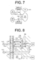
There is known a displacement control mechanism shown in FIG. 7, in
which the pressure in a crank chamber 153 or crank pressure Pc is adjusted by
technique, what is called, a supply control.
Namely, in a variable displacement type swash plate compressor
(hereinafter the compressor), the crank chamber 153 communicates with a
suction chamber 155 via a bleed passage 154. A discharge chamber 151 of the
compressor communicates with the crank chamber 153 via a supply passage 152
in which a control valve 156 is arranged. The amount of refrigerant gas
introduced into the crank chamber 153 via the supply passage 152 is controlled
by adjusting the opening of the control valve 156, and the crank pressure Pc is
determined in accordance with the relation between the amounts of refrigerant
gas introduced into and bleeding from the crank chamber 153.
A fixed throttle 158 is arranged in the bleed passage 154 so that the
refrigerant gas bleeds slowly from the crank chamber 153 to the suction chamber
155. Thus, even when the amount of the refrigerant gas supplied from the
discharge chamber 151 to the crank chamber 153 via the supply passage 152 is
small, the crank pressure Pc is steadily increased. Therefore, when the control
valve 156 increases the opening of the supply passage 152, the crank pressure
Pc is rapidly increased. Consequently, appropriate response in decreasing the
compressor displacement is obtained.
Also, an amount of gas that blows from a cylinder bore 157 to the crank
chamber 153 and that leaks to the suction chamber 155 via the bleed passage
154, and an amount of the refrigerant gas that moves from the discharge
chamber 151 to the suction chamber 155 via the crank chamber 153 as
mentioned above, so-called, a kind of internal leakage, are reduced as much as
possible by the provision of the fixed throttle 158. Consequently, decrease in
efficiency of the compressor caused by providing the displacement control
mechanism is prevented.
However, the arrangement of the fixed throttle 158 on the bleed passage
154 makes decrease in a pressure in the crank chamber 153 slow. In other words,
response in increasing the displacement of the compressor deteriorates.
Especially, when the compressor is started, the crank pressure Pc tends to be
excessively increased since the liquid refrigerant accumulated in the crank
chamber 153 evaporates and the fixed throttle 158 hampers smooth flow of the
refrigerant gas from the crank chamber 153. Therefore, even when the control
valve 156 closes the supply passage 152 so as to increase the displacement of
the compressor in response to the requirement for cooling shortly after the
compressor is started, it takes time before the displacement of the compressor is
actually increased, and starting performance of an air conditioning apparatus
deteriorates.
To solve such problems, it is proposed to provide a second control valve
161 for controlling the opening of the bleed passage 154 in addition to the control
valve (first control valve) 156, as shown in FIG. 8. Please see Japanese
Unexamined Patent Publication No. 2002-21721 (pages 7 to 10, and Figures 1, 4
and 5).
Specifically, in the proposed structure, a region K is provided in the supply
passage 152 downstream of the position of the first control valve 156 (i.e. the
position of the valve opening adjustment) and upstream of a fixed throttle 169, as
shown in FIG. 8. The second control valve 161 is a spool type valve that includes
a spool 162 and a back pressure chamber 166 into which the pressure in the
region K is introduced. A valve chamber 167 of the second control valve 161
forms a part of the bleed passage 154 and communicates with the suction
chamber 155. The valve chamber 167 also communicates with the crank
chamber 153 via a valve hole 168 that forms the upstream portion of the bleed
passage 154.
The spool 162 is movably fitted in a spool supporting recess 164 that is
formed in a compressor housing. The spool 162 includes a valve portion 162a
that is located in the valve chamber 167 and a back surface 162b that is located
in the back pressure chamber 166. The spool 162 or the valve portion 162a is
positioned by various forces applied thereto such as urging force of the pressure
in the back pressure chamber 166 acting on the back surface 162b in the
direction to close the valve, urging force of a spring 165 acting in the valve
opening direction and force of the crank pressure Pc that is applied in the valve
opening direction.
When the first control valve 156 closes the supply passage 152, a
pressure PdK in the back pressure chamber 166 of the second control valve 161
becomes substantially the same as the crank pressure Pc and, therefore, the
spool 162 of the second control valve 161 is positioned by the spring 165 where
the opening of the valve hole 168 is maximum. When the bleed passage 154 is
widely opened by the second control valve 161, flowing of the refrigerant from the
crank chamber 153 to the suction chamber 155 is prompted. Therefore, when the
first control valve 156 closes the supply passage 152 so as to increase the
displacement of the compressor shortly after the compressor is started, the
displacement of the compressor is immediately increased, so that the starting
performance of the air conditioning apparatus is improved.
A spring having a small urging force is utilized as the urging spring 165.
Thus, when the supply passage 152 is opened even slightly by the first control
valve 156 and the pressure PdK in the region K exceeds the crank pressure Pc,
the spool 162 moves against the urging spring 165, and the valve portion 162a
minimizes the opening of the valve hole 168 that is not zero. Therefore, when the
valve hole 168 is thus set at the minimum opening that is not zero, the second
control valve 161 functions similarly to the above-described fixed throttle 158
shown in FIG. 7, and the decrease in the efficiency of the compressor caused by
providing the displacement control mechanism is prevented.
However, the first control valve 156 leaks the refrigerant gas by
performance deterioration due to aged deterioration even in a state that the first
control valve 156 closes the supply passage 152. Thus, the pressure Pdk in the
back pressure chamber 166 of the second control valve 161 rises due to the
refrigerant gas which leaks from the first control valve 156, and the second
control valve 161 may inappropriately set the opening of the bleed passage 154
at the minimum opening. Therefore, the refrigerant gas is flowed slowly from the
crank chamber 153 to the suction chamber 155 through the bleed passage 154,
and the starting performance of the air conditioning apparatus is insufficient.
To solve such a problem, a spring having large urging force is adopted as
the urging spring 165 so that the spool 162 or the valve portion 162a maintains
the maximum opening of the valve hole 168 even if the pressure Pdk in the back
pressure chamber 166 is raised somewhat.
However, when the spring having large urging force is adopted as the
urging spring 165, the second control valve 161 cannot set the bleed passage
154 at the minimum opening unless the first control valve 156 widely opens the
supply passage 152 and the pressure Pdk in the back pressure chamber 166 is
greatly raised. Therefore, in a state that the first control valve 156 opens the
supply passage 152, such period that the second control valve 161 sets the bleed
passage 154 at an opening other than the minimum opening, in other words, such
period that the second control valve 161 cannot function similarly to the fixed
throttle 158 increases, and decrease in the efficiency of the compressor is
caused.
SUMMARY OF THE INVENTION
The present invention is directed to a displacement control mechanism
that prevents a second control valve from inappropriately operating even when
performance of a first control valve deteriorates while preventing decrease in
efficiency of a variable displacement type compressor.
According to the present invention, a displacement control mechanism
controls displacement of a variable displacement type compressor that forms a
refrigerant circulation circuit for an air conditioning apparatus. The displacement
is decreased as a pressure in a crank chamber rises while being increased as the
pressure in the crank chamber falls. The refrigerant circulation circuit has a
suction pressure region and a discharge pressure region. The displacement
control mechanism includes a bleed passage, a supply passage, a first control
valve and a second control valve. The bleed passage interconnects the crank
chamber with the suction pressure region. The supply passage interconnects the
crank chamber with the discharge pressure region. The first control valve is
located on the supply passage for adjusting an opening of the supply passage at
a position of valve opening adjustment. The second control valve includes a back
pressure chamber, a valve chamber, a valve body, a spring and a second valve
portion. A pressure on a downstream side of the position of valve opening
adjustment of the first control valve in the supply passage is introduced to the
back pressure chamber through an introduction passage. The valve chamber
forms a part of the bleed passage. The valve body has a first valve portion
located in the valve chamber and a back surface located in the back pressure
chamber. The first valve portion decreases an opening of the bleed passage as a
pressure in the back pressure chamber which is applied to the back surface rises.
The spring urges the valve body so that the first valve portion increases the
opening of the bleed passage. The second valve portion is provided with the back
surface of the valve body. The second valve portion closes an opening of the
introduction passage in the back pressure chamber when the first valve portion
maximizes the opening of the bleed passage.
Other aspects and advantages of the invention will become apparent
from the following description, taken in conjunction with the accompanying
drawings, illustrating by way of example the principles of the invention.
BRIEF DESCRIPTION OF THE DRAWINGS
The features of the present invention that are believed to be novel are set
forth with particularity in the appended claims. The invention, together with
objects and advantages thereof, may best be understood by reference to the
following description of the presently preferred embodiments together with the
accompanying drawings in which:
DETAILED DESCRIPTION OF THE PREFERRED EMBODIMENTS
The following will describe a preferred embodiment of the present
invention. In the preferred embodiment, the present invention is applied to a
variable displacement type swash plate compressor (hereinafter the compressor)
that is used in a vehicle air conditioning apparatus for compressing refrigerant
gas.
Referring to FIG. 1, the compressor includes a cylinder block 11, a front
housing 12, a valve plate assembly 13 and a rear housing 14. In FIG. 1, the left
side and the right side respectively correspond to the front side and the rear side
of the compressor. The front housing 12 is fixedly joined to the front end of the
cylinder block 11, and the rear housing 14 is fixedly joined to the rear end of the
cylinder block 11 via the valve plate assembly 13. The cylinder block 11, the front
housing 12 and the rear housing 14 cooperate to form a compressor housing.
A crank chamber 15 is defined by the cylinder block 11 and the front
housing 12. A drive shaft 16 is rotatably supported in the crank chamber 15. A lug
plate 17 is fixed to the drive shaft 16 so as to be integrally rotated with the drive
shaft.
The front end of the drive shaft 16 is operatively connected to a vehicle
engine E as an external drive source via a power transmission mechanism PT
The power transmission mechanism PT may be a clutch mechanism (e.g. an
electromagnetic clutch) that selectively transmits and blocks driving power
according to electric control from an external device, or a continuous transmission
type clutchless mechanism (e.g. the combination of a belt and a pulley) that
dispenses with the above clutch mechanism. In the present preferred
embodiment, the clutchless type power transmission mechanism PT is utilized.
A swash plate 18 as a cam plate is accommodated in the crank chamber
15. The swash plate 18 is slidably and inclinably supported by the drive shaft 16.
A hinge mechanism 19 is interposed between the lug plate 17 and the swash
plate 18. Thus, a hinge connection between the lug plate 17 and the swash plate
18 via the hinge mechanism 19 and the support of the swash plate 18 by the drive
shaft 16 allow the swash plate 18 to rotate synchronously with the lug plate 17
and the drive shaft 16 as well as to incline with respect to an axis of the drive shaft
16 in accordance with the sliding movement of the swash plate 18 in the axial
direction of the drive shaft 16.
A plurality of cylinder bores 11a is formed in the cylinder block 11
extending axially through the cylinder block 11 and is arranged around the drive
shaft 16. In FIG. 1, only one cylinder bore is shown. A single-head piston 20 is
accommodated in each of the cylinder bores 11a for reciprocation therein. The
front and rear openings of the cylinder bores 11a are respectively closed by the
pistons 20 and the valve plate assembly 13. Compression chambers are defined
in the cylinder bores 11a, and the volumes of the compression chambers are
varied in accordance with the reciprocating movement of the pistons 20. Each of
the pistons 20 is engaged with the periphery of the swash plate 18 via a pair of
shoes 10, so that the rotation of the swash plate 18 with the drive shaft 6 is
converted into linear reciprocating movement of the pistons 20.
A suction chamber 21 and a discharge chamber 22 are defined between
the valve plate assembly 13 and the rear housing 14. The suction chamber 21 is
located in the middle region of the rear housing 14 and is surrounded by the
discharge chamber 22. A suction port 23 and a suction valve 24 are formed in the
valve plate assembly 13 for each of the cylinder bores 11 a. The suction valve 24
is adapted to open and close the suction port 23. A discharge port 25 and a
discharge valve 26 are also formed in the valve plate assembly 13 for each of the
cylinder bores 11a. The suction chamber 21 communicates with each of the
cylinder bores 11 a via the corresponding suction port 23, and each of the cylinder
bores 11a communicates with the discharge chamber 22 via the corresponding
discharge port 25.
As each of the pistons 20 moves from the top dead center toward the
bottom dead center, the refrigerant gas is drawn into the corresponding cylinder
bore 11 a via the associated suction port 23 pushing away the associated suction
valve 24. As the pistons 20 move from the bottom dead center toward the top
dead center, the refrigerant gas introduced into the cylinder bore 11a is
compressed to a predetermined pressure and is discharged into the discharge
chamber 22 via the associated discharge port 25 pushing away the discharge
valve 26.
An inclination angle of the swash pate 18, which is defined as an angle
made between the swash plate 18 and a plane perpendicular to the axis of the
drive shaft 16 is varied in accordance with the pressure in the crank chamber 5
(or a crank pressure Pc) between the minimum inclination angle as indicated by a
solid line in FIG. 1 and the maximum inclination angle as indicated by a two-dot
chain line in FIG. 1.
A displacement control mechanism for controlling the crank pressure Pc
which has bearing on control of the inclination angle of the swash plate 18
includes a first bleed passage 27, a second bleed passage 28, a supply passage
29, a first control valve CV1 and a second control valve CV2.
The first and second bleed passages 27 and 28 interconnect the crank
chamber 15 with the suction chamber 21 as a suction pressure (Ps) region. The
second bleed passage 28 has a fixed throttle 28a and extends through the
cylinder block 11 and the valve plate assembly 13. The supply passage 29
interconnects the discharge chamber 22 as a discharge pressure (Pd) region with
the crank chamber 15. The first control valve CV1 is arranged in the supply
passage 29 for adjusting the opening of the supply passage 29. It is noted that
the first bleed passage 27 and the supply passage 29 are partially shared
therebetween as will be later described.
The first control valve CV1 adjusts the opening of the supply passage 29
while the second control valve CV2 adjusts the opening of the supply passage 29
and the first bleed passage 27. By so doing, the balance between [an] the amount
of high-pressure discharge gas introduced from the discharge chamber 22 into
the crank chamber 5 via the supply passage 29 and [an] the amount of the
refrigerant gas flowing from the crank chamber 5 into the suction chamber 21 via
the first and second bleed passages 27 and 28 is controlled, and the crank
pressure Pc is determined, accordingly. Pressure difference between the crank
pressure Pc and the internal pressure in the cylinder bores 11 a via the pistons 20
is changed in accordance with the variation of the crank pressure Pc, and the
inclination angle of the swash plate 12 is varied, accordingly. Consequently, the
stroke of pistons 20, that is, the displacement of the compressor is adjusted.
For example, when the first control valve CV1 reduces the opening of the
supply passage 29 and the crank pressure Pc is decreased, the inclination angle
of the swash plate 18 is increased, and the displacement of the compressor is
increased. On the other hand, when the first control valve CV1 increases the
opening of the supply passage 29 and the crank pressure Pc is increased, the
inclination angle of the swash plate 18 is decreased, and the displacement of the
compressor is decreased. It is note that the minimum displacement of the
compressor is set at zero or about zero
A refrigerant circulation circuit (or a refrigeration cycle) of the vehicle air
conditioning apparatus includes the above-described compressor and an external
refrigerant circuit 30. The external refrigerant circuit 30 includes a condenser 31,
an expansion valve 32 and an evaporator 33. A circulation pipe 35 for the
refrigerant is provided on the downstream side of the external refrigerant circuit
30, interconnecting the outlet of the evaporator 33 with the suction chamber 21 of
the compressor. A circulation pipe 36 for the refrigerant is provided on the
upstream side of the external refrigerant circuit 30, interconnecting the discharge
chamber 22 of the compressor with the inlet of the condenser 31. The
compressor draws and compresses therein the refrigerant gas which is
introduced from the downstream side of the external refrigerant circuit 30 into the
suction chamber 21, and then discharges the compressed refrigerant gas to the
discharge chamber 22 which interconnects with the upstream side of the external
refrigerant circuit 30.
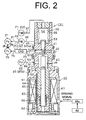
As shown in FIG. 2, the first control valve CV1 includes a valve portion in
the upper half thereof as seen on the drawing of FIG. 2 and a solenoid portion 60
in the lower half. The valve portion adjusts the opening (a degree of throttle) of
the supply passage 29 that interconnects the discharge chamber 22 with the
crank chamber 15. The solenoid portion 60 is an actuator for controlling the
operation of a valve rod 40 arranged in the control valve CV1 in response to a
control signal from an external device. The valve rod 40 is a rod-like member
[and] which includes a partition portion 41 at the top of the rod, a connection
portion 42, a valve body portion 43 at the middle and a guide rod portion 44 at the
base.
A valve housing 45 for the first control valve CV1 includes a valve body
housing 45a [in] forming its upper part and an actuator housing 45b [in] forming its
lower part. A valve accommodating chamber 46, a communication passage 47
and a pressure sensing chamber 48 are defined in the valve body housing 45a.
The valve rod 40 is arranged in the valve accommodating chamber 46 and the
communication passage 47 for axial movement, that is, movement in the vertical
direction [of] as seen in FIG. 2. The partition portion 41 of the valve rod 40 is
inserted [into] through the communication passage 47 thereby to shut off the
communication between the pressure sensing chamber 48 [from] and the
communication passage 47.
Ports 51 and 52 are formed through the peripheral wall of the valve body
housing 45a. The port 51 communicates with the valve accommodating chamber
46, and the port 52 communicates with the communication passage 47,
respectively. The valve accommodating chamber 46 communicates with the
discharge chamber 22 of the compressor via the port 51 and the upstream part of
the supply passage 29, or a passage 84. The communication passage 47
communicates with the crank chamber 15 of the compressor via the port 52, the
downstream part of the supply passage 29 or a passage 83, the second control
valve CV2 and a passage 75. The supply passage 29 includes the passage 84,
the port 51, the valve accommodating chamber 46, the communication passage
47, the port 52, the passage 83, the second control valve CV2 and the passage
75.
The valve body portion 43 of the valve rod 40 is located in the valve
accommodating chamber 46. A valve seat 53 is formed at the stepped portion
located between the valve accommodating chamber 46 and the communication
passage 47, and the communication passage 47 functions as a valve hole. When
the valve rod 40 moves upward from the position of FIG. 2, where the
communication passage 47 (or the supply passage 29) is opened, to a position
where the valve body portion 43 contacts the valve seat 53, the communication
passage 47 (the supply passage 29) is closed.
A bellows 50 is accommodated in the pressure sensing chamber 48. The
upper end of the bellows 50 is fixed to the valve housing 45. The top of the
partition portion 41 of the valve rod 40 is fitted into the lower end of the bellows 50.
The pressure sensing chamber 48 is divided into two chambers by the bellows 50,
namely a first pressure chamber 54 formed inside the bellows and a second
pressure chamber 55 formed outside the bellows50.
As shown in FIG. 1, a throttle 36a is formed on the circulation pipe 36
between the discharge chamber 22 and the external refrigerant circuit 30.
Referring back to FIG. 2, the first pressure chamber 54 communicates via a first
pressure introducing passage 37 with the discharge chamber 22 at a first
pressure monitoring point P1 that is located on the upstream side of the throttle
36a. The second pressure chamber 55 communicates via a second pressure
introducing passage 38 with the circulation pipe 36 at a second pressure
monitoring point P2 that is located on the downstream side of the throttle 36a.
Thus, a monitored pressure PdH at the first pressure monitoring point P1 is
introduced into the first pressure chamber 54, and a monitored pressure PdL at
the second pressure monitoring point P2 is introduced into the second pressure
chamber 55.
The lower end of the bellows 50 vertically moves in accordance with the
pressure difference (PdH - PdL) between the pressures on opposite sides of the
throttle 36a. Thus, the position of the valve rod 40 (or the valve body portion 43) is
determined by varying the pressure difference. The pressure difference (PdH -
PdL) between the pressures on opposite sides of the throttle 36a varies
depending on the refrigerant flow rate in the refrigerant circulation circuit. For
example, when the refrigerant flow rate is increased, the pressure difference
(PdH - PdL) is increased. On the other hand, when the refrigerant flow rate is
decreased, the pressure difference (PdH - PdL) is decreased. The bellows 50
operates the valve body portion 43 such that the displacement of the compressor
is changed so as to cancel the variation of the pressure difference (PdH - PdL)
The solenoid portion 60 of the first control valve CV1 has in the middle of
the actuator housing 45b an accommodating cylinder 61 that has a cylindrical
shape with a bottom. A fixed core 62 of a column shape is fittingly fixed to the
upper opening of the accommodating cylinder 61. Thus, a solenoid chamber 63 is
defined in the lower portion of the accommodating cylinder 61.
A movable core 64 is axially movably accommodated in the solenoid
chamber 63. A guide hole 65 extends through the center of the fixed core 62 in
the axial direction of the valve rod 40. The guide rod portion 44 of the valve rod 40
is arranged in the guide hole 65 so as to move in the axial direction of the valve
rod 40. The guide rod portion 44 is fittingly fixed to the movable core 64 of the
solenoid chamber 63. Thus, the movable core 64 and the valve rod 40 vertically
move together.
A helical spring 66 is accommodated between the fixed core 62 and the
movable core 64 in the solenoid chamber 63 for urging the valve rod 40 in such
direction that causes the valve body portion 43 to move away from the valve seat
53.
A coil 67 is wound around the outer periphery of the accommodating
cylinder 61 over a range covering the fixed core 62 and the movable core 64.
Driving signal is transmitted from a driving circuit 68a to the coil 67, based on the
command from a control device 68 in accordance with air conditioning load. With
such driving signal transmitted to the coil 67, electromagnetic force (or
electromagnetic attraction) is generated between the fixed core 62 and the
movable core 64, the magnitude of which electromagnetic force is determined by
amount of electric power supplied to the coil 67. The electromagnetic force is
transmitted to the valve rod 40 (or the valve body portion 43) through the movable
core 64. Controlling energization of the coil 67 is performed by adjusting the
voltage applied to the coil 67, and duty cycle control is utilized in the present
preferred embodiment.
The solenoid portion 60 of the first control valve CV1 varies the
electromagnetic force for application to the valve body portion 43 in accordance
with the amount of the electric power supplied from an external device. In the first
control valve CV1, therefore, control target (or set pressure difference) for the
pressure difference (PdH - PdL) between the pressures on opposite sides of the
throttle 36a, that is, a standard for positioning the valve body portion 43 by the
bellows 50 is changed by varying the electromagnetic force for application to the
valve body portion 43. In other words, the first control valve CV1 is formed to
internally autonomously position the valve rod 40 (or the valve body portion 43) in
accordance with the variation of the pressure difference (PdH - PdL) between the
first and second pressure monitoring points P1 and P2 such that the set pressure
difference determined by the amount of the electric power supplied to the coil 67
is maintained.
The set pressure difference of the first control valve CV1 is varied by
adjusting the amount of the electric power supplied to the coil 67 from the
external device. For example, when the duty ratio that is commanded from the
control device 68 to the driving circuit 68a is increased, electromagnetic urging
force of the solenoid portion 60 is increased, and the set pressure difference of
the first control valve CV1 is increased, accordingly. With the set pressure
difference of the first control valve CV1 thus increased, the displacement of the
compressor is increased. On the other hand, when the duty ratio that is
commanded from the control device 68 to the driving circuit 68a is decreased,
electromagnetic urging force of the solenoid portion 60 is decreased, and the set
pressure difference of the first control valve CV1 is decreased. When the set
pressure difference of the first control valve CV1 is decreased, the displacement
of the compressor is decreased.
It is noted that the compressor of the present preferred embodiment is
what is called a clutchless type compressor, and the drive shaft 16 is continuously
rotated while the engine E is driven. When the air conditioning is not needed,
however, supplying the electric power to the coil 67 is stopped by switching off the
air conditioning apparatus, that is, the duty ratio is zero, and the swash plate is
set at the minimum inclination angle. Thus, the displacement of the compressor is
set at the minimum displacement, namely, zero or about zero by only one
meaning. Therefore, even when the drive shaft 16 is rotated, supplying the
refrigerant from the compressor to the external refrigerant circuit 30 is
substantially stopped, and the refrigeration cycle is stopped.
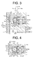
As shown in FIGS. 1, 3 and 4, an accommodation hole 70 is formed in a
rear end surface of the rear housing 4 for accommodating therein the second
control valve CV2. A valve housing 71 is fittingly fixed to the accommodation hole
70. The valve housing 71 includes a cylindrical portion 72 whose outside
diameter is smaller than that of the accommodation hole 70 and a fitting portion
73 that continues from the cylindrical portion 72 on the opening side of
accommodation hole 70 and is fittingly fixed to the accommodation hole 70. The
valve housing 71 is pushed into the accommodation hole 70 such that the distal
end of the cylindrical portion 72 contacts an inner bottom surface 70a of the
accommodation hole 70.
The cylindrical portion 72, the end surface 73a of the fitting portion 73 that
faces the inside of the cylindrical portion 72, and the inner bottom surface 70a of
the accommodation hole 70 define an accommodation chamber 74 in the
cylindrical portion 72. A communication space 79 is formed between the outer
peripheral surface of the cylindrical portion 72 and the inner peripheral surface of
the accommodation hole 70. The communication space 79 communicates with
the crank chamber15 via a passage 75 arranged on the side of the crank
chamber 15.
In the accommodation chamber 74, a spool 76 that serves as a valve
body is movably accommodated in the direction in which the cylindrical portion 72
extends. The spool 76 is slidable between the position at which the spool 76
contacts the inner bottom surface 70a of the accommodation hole 70 and the
position at which the spool 76 contacts the end surface 73a of the fitting portion
73, and has a cylindrical shape with a bottom on the side of the end surface 73a
of the fitting portion 73.
The spool 76 divides the accommodation chamber 74 into front and rear
spaces, which are blocked by the contact between the outer peripheral surface of
the spool 76 and the inner peripheral surface of the accommodation chamber 74.
The blocked front and rear spaces are respectively defined as a valve chamber
77 on the side of the inner bottom surface 70a of the accommodation hole 70 and
a back pressure chamber 78 on the side of the end surface 73a of the fitting
portion 73. In the spool 76, the end surface on the opening side of the spool 76
arranged in the valve chamber 77 is defined as an end valve portion 76a and the
outer bottom surface of the spool 76 arranged in the back pressure chamber 78 is
defined as a back surface 80. The spool 76 contacts the inner bottom surface 70a
of the accommodation hole 70 with the end valve portion 76a.
The cylindrical portion 72 of the valve housing 71 forms a first gap-hole
72a and a second gap-hole 72b therethrough. The first gap-hole 72a
communicates with the inside and the outside of the cylindrical portion 72. The
second gap-hole 72b is located nearer the fitting portion 73 than the first gap-hole
72a, and communicates with the inside and the outside of the cylindrical portion
72.
The first gap-hole 72a communicates with the valve chamber 77 and the
communication space 79 in a state that the spool 76 is in contact with the end
surface 73a of the fitting portion 73 as shown in FIG. 4. The first gap-hole 72a is
blocked by a region on the side of the valve chamber 77 in the outer peripheral
surface of the spool 76, that is, a first peripheral valve portion 76b in a state that
the spool 76 is in contact with the inner bottom surface 70a of the accommodation
hole 70. Thus, the communication between the valve chamber 77 and the
communication space 79 is blocked as shown in FIG. 3.
The second gap-hole 72b communicates with the back pressure chamber
78 and the communication space 79 in a state that the spool 76 is in contact with
the inner bottom surface 70a of the accommodation hole 70 as shown in FIG. 3.
The second gap-hole 72b is blocked by a region on the side of the back pressure
chamber 78 in the outer peripheral surface of the spool 76, that is, a second
peripheral valve portion 76c in a state that the spool 76 is in contact with the end
surface 73a of the fitting portion 73. Thus, the communication between the back
pressure chamber 78 and the communication space 79 is blocked as shown in
FIG. 4.
The valve chamber 77 communicates with the suction chamber 21 via a
passage 81 formed in the rear housing 14. The passage 81 is opened more
inwardly than an annular region or a sealed region in which the end valve portion
76a of the spool 76 contacts the inner bottom surface 70a of the accommodation
hole 70.
Therefore, the communication of the inside and the outside of the valve
chamber 77 relative to the sealed region of the end valve portion 76a are blocked
in a state that the spool 76 is in contact with the inner bottom surface 70a of the
accommodation hole 70. In addition, the first gap-hole 72a is blocked by the first
peripheral valve portion 76b. Thus, the communication between the passage 81
and the communication space 79 (or the passage 75) is blocked as shown in FIG.
3. The communication of the inside and the outside of the valve chamber 77
relative to the sealed region of the end valve portion 76a are opened in a state
that the spool 76 is in contact with the end surface 73a of the fitting portion 73. In
addition, the first gap-hole 72a is opened by the first peripheral valve portion 76b
of the spool 76. Thus, the communication between the passage 81 and the
communication space 79 (or the passage 75) is opened as shown in FIG. 4.
In the present preferred embodiment, the passage 81, the valve chamber
77, the first gap-hole 72a, the communication space 79, and the passage 75
which is shared with the supply passage 29 form the first bleed passage 27.
Therefore, in the spool 76, the end valve portion 76a and the first peripheral valve
portion 76b which open and close the communication between the passage 81
and the communication space 79 are regarded as a first valve portion for
adjusting the opening of the first bleed passage 27.
The back pressure chamber 78 communicates with the port 52 of the first
control valve CV1 via a passage 82 formed in the fitting portion 73 of the valve
housing 71 and a passage 83 that forms the supply passage 29. The passage 82
is opened at an opening 82a formed at the center of the end surface 73a of the
fitting portion 73 in the back pressure chamber 78. Therefore, the refrigerant gas
flowed from the discharge chamber 22 is introduced into the back pressure
chamber 78 via a passage 84, the first control valve CV1 which is in a opening
state, the passages 83 and 82. That is, a pressure Pdk on the downstream side of
the position of the valve opening adjustment of the first control valve CV1, or the
valve seat portion 53, in the supply passage 29 is applied to the back pressure
chamber 78 via the passage 82 that serves as an introduction passage.
The refrigerant gas introduced from the discharge chamber 22 to the
back pressure chamber 78 is flowed into the crank chamber 15 via the second
gap-hole 72b, the communication space 79 and the passage 75. That is, in the
second control valve CV2, the passage 82, the back pressure chamber 78, the
second gap-hole 72b and the communication space 79 form the supply passage
29.
The spool 76 is urged toward the inner bottom surface 70a of the
accommodation hole 70, that is, in such direction that the end valve portion 76a
and the first peripheral valve portion 76b of the first valve portion decrease the
opening of the first bleed passage 27 by the force of the pressure Pdk in the back
pressure chamber 78 applied to the back surface 80. On the other hand, the
spool 76 is urged toward the end surface 73a of the fitting portion 73, that is, in
such direction that the end valve portion 76a and the first peripheral valve portion
76b of the first valve portion increase the opening of the first bleed passage 27 by
the force of the suction pressure Ps which is applied to the end valve portion 76a
and the valve chamber 77.
A helical spring 85 is arranged in the spool 76 of the valve chamber 77.
The spring 85 has a movable end and a fixed end on the opposite sides thereof.
The movable end of the spring 85 is in contact with the spool 76 while the fixed
end of the spring 85 is held and accommodated in an accommodating groove 70b
formed in the inner bottom surface 70a of the accommodation hole 70. The spring
85 urges the spool 76 in such direction that the end valve portion 76a and the first
peripheral valve portion 76b of the first valve portion increase the opening of the
first bleed passage 27.
That is, the spool 76 is positioned by the balance between the urging
force in the valve closing direction of the end valve portion 76a and the first
peripheral valve portion 76b of the first valve portion caused by the force of the
pressure Pdk in the back pressure chamber 78, the urging force in the valve
opening direction of the end valve portion 76a and the first peripheral valve
portion 76b of the first valve portion caused by the force of the pressure Ps in the
valve chamber 77, and the urging force in the valve opening direction of the end
valve portion 76a and the first peripheral valve portion 76b of the first valve
portion caused by the force of the urging force 85.
Meanwhile, in the present embodiment, the back surface 80 of the spool
76 forms thereon a second valve portion 86 for opening and closing the opening
82a of the passage 82 in the back pressure chamber 78 in accordance with the
position of the spool 76. The second valve portion 86 protrudes from the center of
the back surface 80 of the spool 76 so as to face the opening 82a of the passage
82. The second valve portion 86 is shaped into a circular shape in a transverse
section, and is tapered so that the distal end of the second valve portion 86
becomes a minor diameter. The taper shape of the second valve portion 86 is
such shaped that the diameter of the proximal end thereof becomes larger than
that of the opening 82a of the passage 82 and the diameter of the distal end
thereof becomes smaller than that of the opening 82a. The second valve portion
86 is made of resilient material such as synthetic rubber or synthetic resin.
As shown in FIG. 4, the movement of the spool 76 toward the fitting
portion 73 is regulated by the contact of the second valve portion 86 with the end
surface 73a of the fitting portion 73. In such a state that the movement of the
spool 76 is regulated by the contact with the end surface 73a of the fitting portion
73, that is, in a state that the first bleed passage 27 is fully opened by the end
valve portion 76a and the first peripheral valve portion 76b of the first valve
portion, the distal end of the second valve portion 86 enters the inside of the
passage 82 via the opening 82a while a taper surface 86a of the second valve
portion 86 contacts at an annular region on the rim of the opening 82a of the
passage 82. Thus, the communication between the back pressure chamber 78
and the passage 82 is blocked. In addition, in such a state, the second gap-hole
72b is blocked by the second peripheral valve portion 76c of the spool 76. Thus,
the communication between the passage 83 and the communication space 79 (or
the passage 75) is blocked.
In contrast, as shown in FIG. 3, in a state that the movement of the spool
76 is regulated by the contact with the inner bottom surface 70a of the
accommodation hole 70, that is, in a state that the first bleed passage 27 is fully
closed by the end valve portion 76a and the first peripheral valve portion 76b of
the first valve portion, the second valve portion 86 is distanced from the end
surface 73a of the fitting portion 73 and the opening 82a of the passage 82 is
opened. In addition, in such a state, the second gap-hole 72b is opened by the
second peripheral valve portion 76c of the spool 76. Thus, the passage 83 and
the communication space 79 (or the passage 75) are interconnected with each
other.
The operating characteristics of the control valve CV2 will be now
described. As shown in FIG. 3, in a state that the end valve portion 76a and the
first peripheral valve portion 76b of the first valve portion of the spool 76 of the
second control valve CV2 have decreased the opening of the first bleed passage
27 from the fully opening state of the first bleed passage 27, the second valve
portion 86 of the spool 76 opens the division of the back pressure chamber 78
and the passage 82 and the pressure Pdk in the passage 82 is applied to the
back pressure chamber 78. Therefore, in the second control valve CV2, if the
cross sectional area of the back pressure chamber 78 that is perpendicular to the
axial direction of the spool 76 is represented as "SA", and the urging force of the
spring 85 is represented as "f', condition expression (1) for increasing the
opening of the first bleed passage 27 in the second control valve CV2 is
expressed as follows:
(Pdk-Ps) • SA<f
As shown in FIG 4, in the second control valve CV2, in a state that that
the first bleed passage 27 is fully opened by the end valve portion 76a and the
first peripheral valve portion 76b of the first valve portion of the spool 76, the
second valve portion 86 of the spool 76 blocks the communication between the
back pressure chamber 78 and the passage 82. Thus, the pressure Pdk in the
passage 82 is not applied to the back pressure chamber 78. Therefore, the
pressure Pdk in the passage 82 is applied only to the second valve portion 86 of
the back surface 80 of the spool 76. If the cross sectional area at the opening 82a
of the passage 82 that is perpendicular to the axial direction of the passage 82 is
represented as "SB" (< "SA"), condition expression for decreasing the opening of
the first bleed passage 27 in the second control valve CV2 in a state that the first
bleed passage 27 is fully opened is expressed as follows:
(Pdk-Ps) • SB>f
When time has passed for more than a predetermined time after the
vehicle engine E was stopped, the pressure in the refrigerant circulation circuit is
equalized at a relatively small value, and thus the pressure Pdk and the suction
pressure Ps equalized to each other. Since the condition expression (1) is
effective and the condition expression (2) is not effective, as shown in FIG. 4, the
spool 76 moves by the spring 85 and the second valve portion 86 blocks the
supply passage 29. At the same time, the end valve portion 76a and the first
peripheral valve portion 76b of the first valve portion fully opens the first bleed
passage 27.
In a conventional compressor for a vehicle air-conditioning apparatus,
any liquid refrigerant existing on the low pressure side of the external refrigerant
circuit 30 with the vehicle engine E kept at a stop for a long time flows into the
crank chamber 15 via the suction chamber 21 due to the fluid communication
between the crank chamber 15 and the suction chamber 21 via the first and
second bleed passages 27 and 28. Especially, when the temperature in the
engine room where the compressor is located is lower than that in the vehicle
interior, a large amount of the liquid refrigerant flows into the crank chamber 15
via the suction chamber 21 and is accumulated in the crank chamber 15.
Therefore, when the vehicle engine E is started and the compressor is
also started thereby through the clutchless type power transmission mechanism
PT, the liquid refrigerant evaporates under the influence of heat generated by the
vehicle engine E and also of the stirring effect of the swash plate 18, with the
result that the crank pressure Pc tends to be increased regardless the opening of
the first control valve CV1.
For example, when the vehicle engine E is started while the vehicle
interior is hot, the control device 68 is operated in response to the demand from
an occupant to command maximum duty ratio to the drive circuit 68a, and the set
pressure difference of the first control valve CV1 is set at the maximum value,
accordingly, for performing cooling as required from the occupant. For this
purpose, the first control valve CV1 closes the supply passage 29, and no high
pressure refrigerant gas is supplied from the discharge chamber 22 to the back
pressure chamber 78 of the second control valve CV2 and the crank chamber 15.
Therefore, even if evaporation of the liquid refrigerant occurs in the crank
chamber 15, the state wherein the pressure difference between the crank
pressure Pc and the suction pressure Ps does not exceed the urging force f, that
is, the state wherein the condition expression (2) is not effective, continues.
Consequently, the spool 76 of the second control valve CV2 is
maintained by the urging force f of the spring 85 in such a state that the end valve
portion 76a and the first peripheral valve portion 76b of the first valve portion fully
opens the first bleed passage 27, and the liquid refrigerant in the crank chamber
15, as well as the refrigerant gas evaporated from part of the liquid refrigerant, are
immediately flowed into the suction chamber 21 via the fully-opened first bleed
passage 27. Thus, the crank pressure Pc is maintained at a low value since the
first control valve CV1 closes the supply passage 29, and the compressor
increases the inclination angle of the swash plate 18 thereby to increase the
displacement of the compressor to its maximum.
If the first control valve CV1 still closes the supply passage 29 even after
the liquid refrigerant is flowed out of the crank chamber 15, the first bleed
passage 27 is fully opened by the end valve portion 76a and the first peripheral
valve portion 76b of the first valve portion of the second control valve CV2 as
described above. Thus, even if the amount of blow-by gas from the cylinder bores
11a to the crank chamber 15 is increased from the amount initially designed, the
blow-by gas is immediately flowed into the suction chamber 21 via the first and
second bleed passages 27 and 28. Therefore, the crank pressure Pc is
maintained at substantially the same level as the suction pressure Ps, and the
maximum inclination angle of the swash plate 18, that is, the maximum
displacement operation (100% displacement operation) of the compressor is
maintained.
When the vehicle interior is cooled to a certain extent due to the above
maximum displacement operation of the compressor, the control device 68
reduces the duty ratio that is commanded to the driving circuit 68a from the
maximum. Accordingly, the first control valve CV1 opens the supply passage 29
so that the pressure Pdk in the passage 82 exceeds the suction pressure Ps in
the valve chamber 77. Thus, the condition expression (2) is satisfied, so that the
spool 76 moves against the urging force f of the spring 85 in the direction to
reduce the valve opening of the end valve portion 76a and the first peripheral
valve portion 76b of the first valve portion from the fully-opened state as shown in
FIG. 3.
In the second control valve CV2, in a state that the end valve portion 76a
and the first peripheral valve portion 76b of the first valve portion of the spool 76
decreases the opening of the first bleed passage 27 from the fully-opened state,
the second valve portion 86 of the spool 76 opens the division of the back
pressure chamber 78 and the passage 82. Therefore, condition expression (3) for
decreasing the opening of the first bleed passage 27 in the second control valve
CV2 in a state that the first bleed passage 27 is opened but is not fully opened is
expressed as follows:
(Pdk-Ps) • SA>f
The condition expression (3) is effective due to the relation "SA>SB" as long as
the urging force f of the spring 85 is fixed, even if the pressure difference "Pdk-Ps"
between the pressure Pdk in the passage 82 and the pressure Ps in the valve
chamber 77 is smaller than the minimum value that satisfies the condition
expression (2). Therefore, the spool 76 which has been distanced from the
fully-opened state of the first bleed passage 27 by the formation of the condition
expression (2) is moved in the direction to reduce the opening of the first bleed
passage 27 without stopping on the way by the formation of the condition
expression (3). Since the urging force of the spring 85 is relatively small, the spool
76 which has been distanced from the fully-opened state of the first bleed
passage 27 is immediately moved to the closed state of the first bleed passage
27.
Thus, the crank pressure Pc is immediately raised by opening the supply
passage 29 of the first control valve CV1 and closing the first bleed passage 27 of
the second control valve CV2. Consequently, the compressor decreases the
inclination angle of the swash plate 18 thereby to decrease the displacement of
the compressor.
An amount of the compressed refrigerant gas that leaks from the
discharge chamber 22 to the crank chamber 15 further to the suction chamber 21
is reduced to the amount of compressed refrigerant gas which leaks only through
the second bleed passage 28 by closing the first bleed passage 27 in the second
control valve CV2, so that a decrease in the efficiency of the compressor is
prevented. Furthermore, although the refrigerant circulation circuit in the present
preferred embodiment is formed such that the refrigerant circulation stops by
operating the compressor at the minimum displacement (so called an off
operation of the clutchless compressor), the off operation of the compressor is
ensured by closing the first bleed passage 27 in the second control valve CV2.
The present embodiment provides the following advantageous effects.
The present invention is not limited to the above-described embodiment,
but is modified as follows.
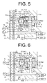
In the above-preferred embodiment, the second control valve CV2 is
arranged on the supply passage 29. In an alternative embodiment to the above
embodiment, as shown in FIG. 5, the second gap-hole 72b of the second control
valve CV2 is eliminated and the passage 83 directly communicates with the crank
chamber 15. In addition, a branch passage 90 is branched off the passage 83 and
communicates with the passage 82 of the second control valve CV2. In this case,
the passage 75 is exclusive for the first bleed passage 27.
In an alternative embodiment to the above embodiment, the aspect of FIG.
5 is partially modified. The minimum opening of the first valve portion 76a and 76b
is set to a value that is not zero by grooving the first valve portion 76a and 76b of
the second control valve CV2 such that the first bleed passage 27 is continuously
opened. The second bleed passage 28 may be eliminated. In this case, the
passages of the displacement control mechanism are simply formed.
In an alternative embodiment to the above embodiment, the aspect of FIG.
5 is partially modified. As shown in FIG. 6, positions at which the passage 75 and
the passage 81 communicate with the second control valve CV2 are replaced by
each other. In addition, a fixed throttle 83a is formed on the passage 83. In this
case, if the first bleed passage 27 is continuously opened by setting the minimum
opening of the first valve portion 76a and 76b at a value that is not zero, and
further if the second bleed passage 28 is eliminated, the second valve portion 86
of the preferred embodiment of the present invention can be applied to the
structure similar to the prior art control valve which is shown in FIG. 8.
In the above-described embodiments, the second valve portion 86 of the
second control valve CV2 is shaped in a protruding shape on the back surface 80
of the spool 76. In alternative embodiments to the above embodiments, the
second valve portion 86 is eliminated from the above-described embodiments.
Instead, the back surface 80 may be regarded as a flat second valve portion by
adhering resilient coat such as rubber coat and resin coat on the back surface 80
of the spool 76. In a technique other than adhering resilient coat on the back
surface 80 of the spool 76 such that the back surface 80 of the spool 76 serves as
a second valve portion, it is proposed that the back surface 80 and the end
surface 73a of the fitting portion 73 are polished in high accuracy.
In the above-described embodiments, the second control valve CV2
opens and closes the supply passage 29 at a plurality of places (at two places of
the second peripheral valve portion 76c and the second valve portion 86). In
alternative embodiments to the above embodiments, the second control valve
CV2 opens and closes the supply passage 29 at a singular place, or at the
second valve portion 86.
In the above-described embodiments, the first valve portion 76a and 76b
of the second control valve CV2 opens and closes the first bleed passage 27 at a
plurality of places (at two places of the end valve portion 76a and the first
peripheral valve portion 76b). In alternative embodiments to the above
embodiments, the first valve portion of the second control valve CV2 opens and
closes the first bleed passage 27 at a singular place such as the end valve portion
76a or the first peripheral valve portion 76b.
In the above-described embodiments, the spool 76 (a tubular body) is
adopted as a valve body of the second control valve CV2. In alternative
embodiments to the above embodiments, a spherical body may be adopted as
the valve body. In this case, a hemispherical part of the spherical body on the side
of the valve chamber 77 forms the first valve portion while the rest hemispherical
part of the spherical body on the side of the back pressure chamber 78 forms the
back surface and the second valve portion.
In the above-described embodiments, the spring 85 is a coil spring. In the
present invention, however, the spring is not limited to the coil spring. Other type
of springs such as plate spring and torsion bar may be adopted.
In the above-described embodiments, the first control valve CV1 varies
the displacement of the compressor such that the pressure difference (PdH-PdL)
between the pressures on opposite sides of the throttle 36a is maintained at a
predetermined target value (set pressure difference). Also, in the first control
valve CV1, the set pressure difference is varied by external electric control. In
alternative embodiments to the above embodiments, the first control valve CV1 is
operated such that the pressure in the suction pressure region is maintained at a
predetermined target value (set suction pressure) while the set suction pressure
is varied by external electric control. In this case, the first control valve CV1 is
so-called a control valve of variable set suction pressure type.
In the above-described embodiments, pressure sensing mechanism such
as the pressure sensing chamber 48 and the bellows 50 may be eliminated from
the first control valve CV1, and the first control valve CV1 may be varied to a
simple electromagnetic valve.
In the above-described embodiments, the solenoid 60 may be eliminated
from the first control valve CV1, and the first control valve CV1 may be varied to a
simple pressure sensing valve which does not provide with external control
function.
The present invention may be applied to a displacement control device
for a variable displacement type compressor of a wobble type.
Therefore, the present examples and embodiments are to be considered
as illustrative and not restrictive and the invention is not to be limited to the details
given herein but may be modified within the scope of the appended claims.
A displacement control mechanism controls displacement of a variable
displacement type compressor that forms a refrigerant circulation circuit for an air
conditioning apparatus. The displacement is decreased as a pressure in a crank
chamber rises while being increased as the pressure in the crank chamber falls.
The displacement control mechanism includes a bleed passage, a supply
passage, a first control valve and a second control valve. The second control
valve includes a back pressure chamber, a valve chamber, a valve body, a spring
and a second valve portion. The second valve portion is provided with the back
surface of the valve body. The second valve portion closes an opening of an
introduction passage in the back pressure chamber when the first valve portion
maximizes the opening of the bleed passage.