EP1489288A2 - Method and device for exhaust purification of an internal combustion engine - Google Patents
Method and device for exhaust purification of an internal combustion engine Download PDFInfo
- Publication number
- EP1489288A2 EP1489288A2 EP04013976A EP04013976A EP1489288A2 EP 1489288 A2 EP1489288 A2 EP 1489288A2 EP 04013976 A EP04013976 A EP 04013976A EP 04013976 A EP04013976 A EP 04013976A EP 1489288 A2 EP1489288 A2 EP 1489288A2
- Authority
- EP
- European Patent Office
- Prior art keywords
- exhaust gas
- storing catalyst
- absorbent
- fuel ratio
- air
- Prior art date
- Legal status (The legal status is an assumption and is not a legal conclusion. Google has not performed a legal analysis and makes no representation as to the accuracy of the status listed.)
- Withdrawn
Links
Images


Classifications
-
- F—MECHANICAL ENGINEERING; LIGHTING; HEATING; WEAPONS; BLASTING
- F02—COMBUSTION ENGINES; HOT-GAS OR COMBUSTION-PRODUCT ENGINE PLANTS
- F02D—CONTROLLING COMBUSTION ENGINES
- F02D41/00—Electrical control of supply of combustible mixture or its constituents
- F02D41/02—Circuit arrangements for generating control signals
- F02D41/04—Introducing corrections for particular operating conditions
- F02D41/06—Introducing corrections for particular operating conditions for engine starting or warming up
- F02D41/062—Introducing corrections for particular operating conditions for engine starting or warming up for starting
-
- F—MECHANICAL ENGINEERING; LIGHTING; HEATING; WEAPONS; BLASTING
- F01—MACHINES OR ENGINES IN GENERAL; ENGINE PLANTS IN GENERAL; STEAM ENGINES
- F01N—GAS-FLOW SILENCERS OR EXHAUST APPARATUS FOR MACHINES OR ENGINES IN GENERAL; GAS-FLOW SILENCERS OR EXHAUST APPARATUS FOR INTERNAL-COMBUSTION ENGINES
- F01N3/00—Exhaust or silencing apparatus having means for purifying, rendering innocuous, or otherwise treating exhaust
- F01N3/02—Exhaust or silencing apparatus having means for purifying, rendering innocuous, or otherwise treating exhaust for cooling, or for removing solid constituents of, exhaust
- F01N3/021—Exhaust or silencing apparatus having means for purifying, rendering innocuous, or otherwise treating exhaust for cooling, or for removing solid constituents of, exhaust by means of filters
- F01N3/023—Exhaust or silencing apparatus having means for purifying, rendering innocuous, or otherwise treating exhaust for cooling, or for removing solid constituents of, exhaust by means of filters using means for regenerating the filters, e.g. by burning trapped particles
- F01N3/0231—Exhaust or silencing apparatus having means for purifying, rendering innocuous, or otherwise treating exhaust for cooling, or for removing solid constituents of, exhaust by means of filters using means for regenerating the filters, e.g. by burning trapped particles using special exhaust apparatus upstream of the filter for producing nitrogen dioxide, e.g. for continuous filter regeneration systems [CRT]
-
- F—MECHANICAL ENGINEERING; LIGHTING; HEATING; WEAPONS; BLASTING
- F01—MACHINES OR ENGINES IN GENERAL; ENGINE PLANTS IN GENERAL; STEAM ENGINES
- F01N—GAS-FLOW SILENCERS OR EXHAUST APPARATUS FOR MACHINES OR ENGINES IN GENERAL; GAS-FLOW SILENCERS OR EXHAUST APPARATUS FOR INTERNAL-COMBUSTION ENGINES
- F01N3/00—Exhaust or silencing apparatus having means for purifying, rendering innocuous, or otherwise treating exhaust
- F01N3/02—Exhaust or silencing apparatus having means for purifying, rendering innocuous, or otherwise treating exhaust for cooling, or for removing solid constituents of, exhaust
- F01N3/021—Exhaust or silencing apparatus having means for purifying, rendering innocuous, or otherwise treating exhaust for cooling, or for removing solid constituents of, exhaust by means of filters
- F01N3/033—Exhaust or silencing apparatus having means for purifying, rendering innocuous, or otherwise treating exhaust for cooling, or for removing solid constituents of, exhaust by means of filters in combination with other devices
- F01N3/035—Exhaust or silencing apparatus having means for purifying, rendering innocuous, or otherwise treating exhaust for cooling, or for removing solid constituents of, exhaust by means of filters in combination with other devices with catalytic reactors
-
- F—MECHANICAL ENGINEERING; LIGHTING; HEATING; WEAPONS; BLASTING
- F01—MACHINES OR ENGINES IN GENERAL; ENGINE PLANTS IN GENERAL; STEAM ENGINES
- F01N—GAS-FLOW SILENCERS OR EXHAUST APPARATUS FOR MACHINES OR ENGINES IN GENERAL; GAS-FLOW SILENCERS OR EXHAUST APPARATUS FOR INTERNAL-COMBUSTION ENGINES
- F01N3/00—Exhaust or silencing apparatus having means for purifying, rendering innocuous, or otherwise treating exhaust
- F01N3/08—Exhaust or silencing apparatus having means for purifying, rendering innocuous, or otherwise treating exhaust for rendering innocuous
- F01N3/0807—Exhaust or silencing apparatus having means for purifying, rendering innocuous, or otherwise treating exhaust for rendering innocuous by using absorbents or adsorbents
- F01N3/0814—Exhaust or silencing apparatus having means for purifying, rendering innocuous, or otherwise treating exhaust for rendering innocuous by using absorbents or adsorbents combined with catalytic converters, e.g. NOx absorption/storage reduction catalysts
-
- F—MECHANICAL ENGINEERING; LIGHTING; HEATING; WEAPONS; BLASTING
- F01—MACHINES OR ENGINES IN GENERAL; ENGINE PLANTS IN GENERAL; STEAM ENGINES
- F01N—GAS-FLOW SILENCERS OR EXHAUST APPARATUS FOR MACHINES OR ENGINES IN GENERAL; GAS-FLOW SILENCERS OR EXHAUST APPARATUS FOR INTERNAL-COMBUSTION ENGINES
- F01N3/00—Exhaust or silencing apparatus having means for purifying, rendering innocuous, or otherwise treating exhaust
- F01N3/08—Exhaust or silencing apparatus having means for purifying, rendering innocuous, or otherwise treating exhaust for rendering innocuous
- F01N3/0807—Exhaust or silencing apparatus having means for purifying, rendering innocuous, or otherwise treating exhaust for rendering innocuous by using absorbents or adsorbents
- F01N3/0821—Exhaust or silencing apparatus having means for purifying, rendering innocuous, or otherwise treating exhaust for rendering innocuous by using absorbents or adsorbents combined with particulate filter
-
- F—MECHANICAL ENGINEERING; LIGHTING; HEATING; WEAPONS; BLASTING
- F01—MACHINES OR ENGINES IN GENERAL; ENGINE PLANTS IN GENERAL; STEAM ENGINES
- F01N—GAS-FLOW SILENCERS OR EXHAUST APPARATUS FOR MACHINES OR ENGINES IN GENERAL; GAS-FLOW SILENCERS OR EXHAUST APPARATUS FOR INTERNAL-COMBUSTION ENGINES
- F01N3/00—Exhaust or silencing apparatus having means for purifying, rendering innocuous, or otherwise treating exhaust
- F01N3/08—Exhaust or silencing apparatus having means for purifying, rendering innocuous, or otherwise treating exhaust for rendering innocuous
- F01N3/0807—Exhaust or silencing apparatus having means for purifying, rendering innocuous, or otherwise treating exhaust for rendering innocuous by using absorbents or adsorbents
- F01N3/0828—Exhaust or silencing apparatus having means for purifying, rendering innocuous, or otherwise treating exhaust for rendering innocuous by using absorbents or adsorbents characterised by the absorbed or adsorbed substances
- F01N3/0842—Nitrogen oxides
-
- F—MECHANICAL ENGINEERING; LIGHTING; HEATING; WEAPONS; BLASTING
- F01—MACHINES OR ENGINES IN GENERAL; ENGINE PLANTS IN GENERAL; STEAM ENGINES
- F01N—GAS-FLOW SILENCERS OR EXHAUST APPARATUS FOR MACHINES OR ENGINES IN GENERAL; GAS-FLOW SILENCERS OR EXHAUST APPARATUS FOR INTERNAL-COMBUSTION ENGINES
- F01N3/00—Exhaust or silencing apparatus having means for purifying, rendering innocuous, or otherwise treating exhaust
- F01N3/08—Exhaust or silencing apparatus having means for purifying, rendering innocuous, or otherwise treating exhaust for rendering innocuous
- F01N3/0807—Exhaust or silencing apparatus having means for purifying, rendering innocuous, or otherwise treating exhaust for rendering innocuous by using absorbents or adsorbents
- F01N3/0871—Exhaust or silencing apparatus having means for purifying, rendering innocuous, or otherwise treating exhaust for rendering innocuous by using absorbents or adsorbents using means for controlling, e.g. purging, the absorbents or adsorbents
-
- F—MECHANICAL ENGINEERING; LIGHTING; HEATING; WEAPONS; BLASTING
- F02—COMBUSTION ENGINES; HOT-GAS OR COMBUSTION-PRODUCT ENGINE PLANTS
- F02D—CONTROLLING COMBUSTION ENGINES
- F02D41/00—Electrical control of supply of combustible mixture or its constituents
- F02D41/02—Circuit arrangements for generating control signals
- F02D41/021—Introducing corrections for particular conditions exterior to the engine
- F02D41/0235—Introducing corrections for particular conditions exterior to the engine in relation with the state of the exhaust gas treating apparatus
- F02D41/024—Introducing corrections for particular conditions exterior to the engine in relation with the state of the exhaust gas treating apparatus to increase temperature of the exhaust gas treating apparatus
- F02D41/025—Introducing corrections for particular conditions exterior to the engine in relation with the state of the exhaust gas treating apparatus to increase temperature of the exhaust gas treating apparatus by changing the composition of the exhaust gas, e.g. for exothermic reaction on exhaust gas treating apparatus
-
- F—MECHANICAL ENGINEERING; LIGHTING; HEATING; WEAPONS; BLASTING
- F02—COMBUSTION ENGINES; HOT-GAS OR COMBUSTION-PRODUCT ENGINE PLANTS
- F02D—CONTROLLING COMBUSTION ENGINES
- F02D41/00—Electrical control of supply of combustible mixture or its constituents
- F02D41/02—Circuit arrangements for generating control signals
- F02D41/021—Introducing corrections for particular conditions exterior to the engine
- F02D41/0235—Introducing corrections for particular conditions exterior to the engine in relation with the state of the exhaust gas treating apparatus
- F02D41/027—Introducing corrections for particular conditions exterior to the engine in relation with the state of the exhaust gas treating apparatus to purge or regenerate the exhaust gas treating apparatus
- F02D41/0275—Introducing corrections for particular conditions exterior to the engine in relation with the state of the exhaust gas treating apparatus to purge or regenerate the exhaust gas treating apparatus the exhaust gas treating apparatus being a NOx trap or adsorbent
-
- F—MECHANICAL ENGINEERING; LIGHTING; HEATING; WEAPONS; BLASTING
- F01—MACHINES OR ENGINES IN GENERAL; ENGINE PLANTS IN GENERAL; STEAM ENGINES
- F01N—GAS-FLOW SILENCERS OR EXHAUST APPARATUS FOR MACHINES OR ENGINES IN GENERAL; GAS-FLOW SILENCERS OR EXHAUST APPARATUS FOR INTERNAL-COMBUSTION ENGINES
- F01N2610/00—Adding substances to exhaust gases
- F01N2610/03—Adding substances to exhaust gases the substance being hydrocarbons, e.g. engine fuel
-
- F—MECHANICAL ENGINEERING; LIGHTING; HEATING; WEAPONS; BLASTING
- F02—COMBUSTION ENGINES; HOT-GAS OR COMBUSTION-PRODUCT ENGINE PLANTS
- F02B—INTERNAL-COMBUSTION PISTON ENGINES; COMBUSTION ENGINES IN GENERAL
- F02B2275/00—Other engines, components or details, not provided for in other groups of this subclass
- F02B2275/14—Direct injection into combustion chamber
-
- F—MECHANICAL ENGINEERING; LIGHTING; HEATING; WEAPONS; BLASTING
- F02—COMBUSTION ENGINES; HOT-GAS OR COMBUSTION-PRODUCT ENGINE PLANTS
- F02B—INTERNAL-COMBUSTION PISTON ENGINES; COMBUSTION ENGINES IN GENERAL
- F02B37/00—Engines characterised by provision of pumps driven at least for part of the time by exhaust
-
- F—MECHANICAL ENGINEERING; LIGHTING; HEATING; WEAPONS; BLASTING
- F02—COMBUSTION ENGINES; HOT-GAS OR COMBUSTION-PRODUCT ENGINE PLANTS
- F02D—CONTROLLING COMBUSTION ENGINES
- F02D2250/00—Engine control related to specific problems or objectives
- F02D2250/36—Control for minimising NOx emissions
-
- F—MECHANICAL ENGINEERING; LIGHTING; HEATING; WEAPONS; BLASTING
- F02—COMBUSTION ENGINES; HOT-GAS OR COMBUSTION-PRODUCT ENGINE PLANTS
- F02D—CONTROLLING COMBUSTION ENGINES
- F02D41/00—Electrical control of supply of combustible mixture or its constituents
- F02D41/0025—Controlling engines characterised by use of non-liquid fuels, pluralities of fuels, or non-fuel substances added to the combustible mixtures
- F02D41/0047—Controlling exhaust gas recirculation [EGR]
- F02D41/005—Controlling exhaust gas recirculation [EGR] according to engine operating conditions
- F02D41/0057—Specific combustion modes
-
- F—MECHANICAL ENGINEERING; LIGHTING; HEATING; WEAPONS; BLASTING
- F02—COMBUSTION ENGINES; HOT-GAS OR COMBUSTION-PRODUCT ENGINE PLANTS
- F02D—CONTROLLING COMBUSTION ENGINES
- F02D41/00—Electrical control of supply of combustible mixture or its constituents
- F02D41/02—Circuit arrangements for generating control signals
- F02D41/021—Introducing corrections for particular conditions exterior to the engine
- F02D41/0235—Introducing corrections for particular conditions exterior to the engine in relation with the state of the exhaust gas treating apparatus
- F02D41/027—Introducing corrections for particular conditions exterior to the engine in relation with the state of the exhaust gas treating apparatus to purge or regenerate the exhaust gas treating apparatus
- F02D41/0275—Introducing corrections for particular conditions exterior to the engine in relation with the state of the exhaust gas treating apparatus to purge or regenerate the exhaust gas treating apparatus the exhaust gas treating apparatus being a NOx trap or adsorbent
- F02D41/028—Desulfurisation of NOx traps or adsorbent
-
- F—MECHANICAL ENGINEERING; LIGHTING; HEATING; WEAPONS; BLASTING
- F02—COMBUSTION ENGINES; HOT-GAS OR COMBUSTION-PRODUCT ENGINE PLANTS
- F02D—CONTROLLING COMBUSTION ENGINES
- F02D41/00—Electrical control of supply of combustible mixture or its constituents
- F02D41/02—Circuit arrangements for generating control signals
- F02D41/021—Introducing corrections for particular conditions exterior to the engine
- F02D41/0235—Introducing corrections for particular conditions exterior to the engine in relation with the state of the exhaust gas treating apparatus
- F02D41/027—Introducing corrections for particular conditions exterior to the engine in relation with the state of the exhaust gas treating apparatus to purge or regenerate the exhaust gas treating apparatus
- F02D41/029—Introducing corrections for particular conditions exterior to the engine in relation with the state of the exhaust gas treating apparatus to purge or regenerate the exhaust gas treating apparatus the exhaust gas treating apparatus being a particulate filter
-
- F—MECHANICAL ENGINEERING; LIGHTING; HEATING; WEAPONS; BLASTING
- F02—COMBUSTION ENGINES; HOT-GAS OR COMBUSTION-PRODUCT ENGINE PLANTS
- F02D—CONTROLLING COMBUSTION ENGINES
- F02D41/00—Electrical control of supply of combustible mixture or its constituents
- F02D41/30—Controlling fuel injection
- F02D41/38—Controlling fuel injection of the high pressure type
- F02D41/40—Controlling fuel injection of the high pressure type with means for controlling injection timing or duration
- F02D41/402—Multiple injections
- F02D41/403—Multiple injections with pilot injections
-
- F—MECHANICAL ENGINEERING; LIGHTING; HEATING; WEAPONS; BLASTING
- F02—COMBUSTION ENGINES; HOT-GAS OR COMBUSTION-PRODUCT ENGINE PLANTS
- F02M—SUPPLYING COMBUSTION ENGINES IN GENERAL WITH COMBUSTIBLE MIXTURES OR CONSTITUENTS THEREOF
- F02M26/00—Engine-pertinent apparatus for adding exhaust gases to combustion-air, main fuel or fuel-air mixture, e.g. by exhaust gas recirculation [EGR] systems
- F02M26/02—EGR systems specially adapted for supercharged engines
- F02M26/04—EGR systems specially adapted for supercharged engines with a single turbocharger
- F02M26/05—High pressure loops, i.e. wherein recirculated exhaust gas is taken out from the exhaust system upstream of the turbine and reintroduced into the intake system downstream of the compressor
-
- F—MECHANICAL ENGINEERING; LIGHTING; HEATING; WEAPONS; BLASTING
- F02—COMBUSTION ENGINES; HOT-GAS OR COMBUSTION-PRODUCT ENGINE PLANTS
- F02M—SUPPLYING COMBUSTION ENGINES IN GENERAL WITH COMBUSTIBLE MIXTURES OR CONSTITUENTS THEREOF
- F02M26/00—Engine-pertinent apparatus for adding exhaust gases to combustion-air, main fuel or fuel-air mixture, e.g. by exhaust gas recirculation [EGR] systems
- F02M26/13—Arrangement or layout of EGR passages, e.g. in relation to specific engine parts or for incorporation of accessories
- F02M26/14—Arrangement or layout of EGR passages, e.g. in relation to specific engine parts or for incorporation of accessories in relation to the exhaust system
- F02M26/16—Arrangement or layout of EGR passages, e.g. in relation to specific engine parts or for incorporation of accessories in relation to the exhaust system with EGR valves located at or near the connection to the exhaust system
-
- F—MECHANICAL ENGINEERING; LIGHTING; HEATING; WEAPONS; BLASTING
- F02—COMBUSTION ENGINES; HOT-GAS OR COMBUSTION-PRODUCT ENGINE PLANTS
- F02M—SUPPLYING COMBUSTION ENGINES IN GENERAL WITH COMBUSTIBLE MIXTURES OR CONSTITUENTS THEREOF
- F02M26/00—Engine-pertinent apparatus for adding exhaust gases to combustion-air, main fuel or fuel-air mixture, e.g. by exhaust gas recirculation [EGR] systems
- F02M26/13—Arrangement or layout of EGR passages, e.g. in relation to specific engine parts or for incorporation of accessories
- F02M26/22—Arrangement or layout of EGR passages, e.g. in relation to specific engine parts or for incorporation of accessories with coolers in the recirculation passage
- F02M26/23—Layout, e.g. schematics
-
- Y—GENERAL TAGGING OF NEW TECHNOLOGICAL DEVELOPMENTS; GENERAL TAGGING OF CROSS-SECTIONAL TECHNOLOGIES SPANNING OVER SEVERAL SECTIONS OF THE IPC; TECHNICAL SUBJECTS COVERED BY FORMER USPC CROSS-REFERENCE ART COLLECTIONS [XRACs] AND DIGESTS
- Y02—TECHNOLOGIES OR APPLICATIONS FOR MITIGATION OR ADAPTATION AGAINST CLIMATE CHANGE
- Y02T—CLIMATE CHANGE MITIGATION TECHNOLOGIES RELATED TO TRANSPORTATION
- Y02T10/00—Road transport of goods or passengers
- Y02T10/10—Internal combustion engine [ICE] based vehicles
- Y02T10/12—Improving ICE efficiencies
Definitions
- the present invention relates to an exhaust purification device and exhaust purification method of an internal combustion engine.
- a catalyst for purifying NO x contained in exhaust gas when fuel is burned under a lean air-fuel ratio there is known a catalyst comprised of a carrier made of alumina on the surface of which a layer of a NO x absorbent comprised of an alkali metal or alkali earth is formed and on the surface of which a precious metal catalyst such as platinum is carried (for example, see Japanese Unexamined Patent Publication (Kokai) No. 6-108826).
- the inventors researched catalysts designed to perform this NO x absorption and release action and as a result discovered that while the nitrogen monoxide contained in exhaust gas is not absorbed in the NO x absorbent when the catalyst is not activated, nitrogen dioxide contained in exhaust gas is stored in the NO x absorbent even when the catalyst is not activated.
- An object of the present invention is to provide an exhaust purification device and exhaust purification method designed to purify exhaust gas utilizing this fact discovered by the inventors.
- an exhaust purification device comprising a NO x storing catalyst comprised of a precious metal catalyst and a NO x absorbent and arranged in an engine exhaust passage, the NO x absorbent storing nitrogen dioxide NO 2 contained in the exhaust gas when an air-fuel ratio of exhaust gas flowing into the NO x storing catalyst is lean when the NO x storing catalyst is not activated, the NO x absorbent storing nitrogen oxides NO x contained in exhaust gas when the air-fuel ratio of the exhaust gas flowing into the NO x storing catalyst is lean when the NO x storing catalyst is activated, the NO x absorbent releasing stored nitrogen oxides NO x when the air-fuel ratio of the exhaust gas flowing into the NO x storing catalyst becomes the stoichiometric air-fuel ratio or rich; NO 2 ratio increasing means for increasing a ratio of nitrogen dioxide NO 2 with respect to nitrogen monoxide NO produced when burning fuel under a lean air-fuel ratio when the NO x storing catalyst is not activated
- an exhaust purification method of an internal combustion engine comprising using a NO x storing catalyst comprised of a precious metal catalyst and a NO x absorbent as a catalyst for purifying NO x in exhaust gas; increasing a ratio of nitrogen dioxide NO 2 with respect to nitrogen monoxide NO produced when burning fuel under a lean air-fuel ratio when the NO x storing catalyst is not activated compared with when the NO x storing catalyst is activated under the same engine operating conditions; storing the nitrogen dioxide NO 2 contained in the exhaust gas in the NO x absorbent at that time; changing nitrogen dioxide NO 2 stored in the NO x absorbent to nitric acid ions NO 3 - when the temperature of the NO x storing catalyst rises; cyclically temporarily switching the air-fuel ratio of the exhaust gas flowing into the NO x storing catalyst from lean to a stoichiometric air-fuel ratio or rich when the NO x storing catalyst is activated; and thereby releasing nitrogen oxides NO x
- FIG. 1 shows the case of application of the present invention to a compression ignition type internal combustion engine. Note that the present invention may also be applied to a spark ignition type internal combustion engine.
- 1 indicates an engine body, 2 a combustion chamber of each cylinder, 3 an electronically controlled fuel injector for injecting fuel into each combustion chamber 2, 4 an intake manifold, and 5 an exhaust manifold.
- the intake manifold 4 is connected through an intake duct 6 to an outlet of a compressor 7a of an exhaust turbocharger 7.
- the inlet of the compressor 7a is connected to an air cleaner 8.
- a throttle valve 9 driven by a step motor.
- a cooling device 10 for cooling the intake air flowing through the inside of the intake duct 6.
- the engine cooling water is guided into the cooling device 10. The engine cooling water cools the intake air.
- the exhaust manifold 5 is connected to an inlet of an exhaust turbine 7b of the exhaust turbocharger 7, while the outlet of the exhaust turbine 7b is connected to a casing 12 housing a NO x storing catalyst 11.
- the outlet of the collecting portion of the exhaust manifold 5 is provided with a reducing agent supply valve 13 for supplying a reducing agent comprised of for example hydrocarbons into the exhaust gas flowing through the inside of the exhaust manifold 5.
- the exhaust manifold 5 and the intake manifold 4 are linked together through an exhaust gas recirculation (hereinafter referred to as an "EGR") passage 14.
- the EGR passage 14 is provided with an electronically controlled EGR control valve 15.
- a cooling device 16 for cooling the EGR gas flowing through the inside of the EGR passage 14.
- the engine cooling water is guided into the cooling device 16.
- the engine cooling water cools the EGR gas.
- each fuel injector 3 is linked through a fuel feed tube 17 to a fuel reservoir, that is, a so-called common rail 18.
- This common rail 18 is supplied with fuel from an electronically controlled variable discharge fuel pump 19.
- the fuel supplied into the common rail 18 is supplied through each fuel feed tube 17 to the fuel injector 3.
- An electronic control unit 30 is comprised of a digital computer provided with a read only memory (ROM) 32, a random access memory (RAM) 33, a microprocessor (CPU) 34, an input port 35, and an output port 36 all connected to each other by a bidirectional bus 31.
- the NO x storing catalyst 11 is provided with a temperature sensor 20 for detecting the temperature of the NO x storing catalyst 11.
- the output signal of the temperature sensor 20 is input to the input port 35 through a corresponding AD converter 37.
- an accelerator pedal 40 has a load sensor 41 generating an output voltage proportional to the amount of depression L through a corresponding AD converter 37 connected to it.
- the output voltage of the load sensor 41 is input to the input port 35 through a corresponding AD converter 37.
- the input port 35 has a crank angle sensor 42 generating an output pulse each time the crankshaft turns for example by 15 degrees connected to it. Further, the input port 35 receives as input an on/off signal of an ignition switch 43.
- the output port 36 is connected through corresponding drive circuits 38 to the fuel injectors 3, throttle valve 9 step motor, reducing agent supply valve 13, EGR control valve 15, and fuel pump 19.
- the NO x storing catalyst 11 shown in FIG. 1 is comprised of a monolithic catalyst.
- a base of the NO x storing catalyst 11 carries for example a catalyst carrier comprised of alumina.
- FIGS. 2A and 2B schematically show the cross-section of the surface part of this catalyst carrier 45.
- the catalyst carrier 45 carries a precious metal catalyst 46 dispersed on its surface.
- the catalyst carrier 45 is formed with a layer of a NO x absorbent 47 on its surface.
- platinum Pt is used as the precious metal catalyst 46.
- the ingredient forming the NO x absorbent 47 for example, at least one element selected from potassium K, sodium Na, cesium Cs, or another alkali metal, barium Ba, calcium Ca, or another alkali earth, lanthanum La, yttrium Y, or another rare earth may be used.
- the NO x absorbent 47 performs a NO x absorption and release action of absorbing NO x when the air-fuel ratio of the exhaust gas is lean when the previous metal catalyst 46 is activated, that is, when the NO x storing catalyst 11 is activated, and releasing the absorbed NO x when the oxygen concentration in the exhaust gas falls.
- the NO x absorbent 47 absorbs NO x when the air-fuel ratio of the air-fuel mixture supplied into the combustion chambers 2 is lean, while releases the absorbed NO x when the oxygen concentration in the air-fuel mixture supplied to the combustion chambers 2 falls.
- the precious metal catalyst 46 when the air-fuel ratio of the exhaust gas is lean, that is, when the oxygen concentration in the exhaust gas is high, if the precious metal catalyst 46 is activated, the NO contained in the exhaust gas is oxidized on the platinum Pt 46 such as shown in FIG. 2A to become NO 2 , then is absorbed in the NO x absorbent 47 and disperses in the NO x absorbent 47 in the form of sulfuric acid ions NO 3 - while bonding with the barium oxide BaO. In this way, the NO x is absorbed in the NO x absorbent 47.
- the oxygen concentration in the exhaust gas falls, so the reaction proceeds in the reverse direction (NO 3 - ⁇ NO 2 ) and therefore the nitric acid ions NO 3 - in the NO x absorbent 47 are released from the NO x absorbent 47 in the form of NO 2 .
- the released NO x is reduced by the unburned HC and CO contained in the exhaust gas.
- the platinum Pt 46 inherently has activity at a low temperature.
- the basicity of the NO x absorbent 47 is considerably strong. Therefore, the activity of the platinum Pt 46 at a low temperature, that is, the acidity, ends up becoming weak.
- the temperature TC of the nitrogen storing catalyst 11 falls, the oxidation action of the NO becomes weaker.
- the temperature TC of the nitrogen storing catalyst 11 falls as shown in FIG. 3, the NO x purification rate falls.
- the temperature TC of the nitrogen storing catalyst 11 falls below about 250°C, the NO x purification rate falls rapidly.
- the NO x purification rate becomes about 50 percent.
- the nitrogen oxides NO x in the exhaust gas are not absorbed in the NO x absorbent 47 in the form of nitrogen monoxide NO. They have to be converted to the form of nitrogen dioxide NO 2 or else will not be absorbed in the NO x absorbent 47. That is, the majority of the nitrogen oxides NO x contained in exhaust gas is usually nitrogen monoxide NO. This nitrogen monoxide NO has to be converted to nitrogen dioxide NO 2 , that is, has to be oxidized, or will not be absorbed in the NO x absorbent 47. To oxidize nitrogen monoxide NO, it is necessary that the precious metal catalyst 46 be activated. Therefore, up until now, to purify NO x , it had been considered necessary that the precious metal catalyst 46 be activated.
- the inventors engaged in research on this nitrogen storing catalyst 11 and as a result learned that the nitrogen monoxide contained in exhaust gas is not absorbed in the NO x absorbent 47 if the platinum 46 is not activated, that is, if the nitrogen storing catalyst 11 is not activated, but the nitrogen dioxide is stored in the NO x absorbent 47 in the form of for example nitric acid NO 2 - as shown in FIG. 2B even if the nitrogen storing catalyst 11 is not activated. Note that in this case, it is not necessarily clear whether the nitrogen dioxide NO 2 is adsorbed at the NO x absorbent 47 or is absorbed in the NO x absorbent 47. This adsorption and absorption are referred to together as "storage".
- the nitrogen dioxide NO 2 is stored even without the NO x storing catalyst 11 being activated, when the NO x storing catalyst 11 is not activated, for example for a while after the engine startup, it is preferable to reduce the amount of nitrogen monoxide NO in the exhaust gas and increase the amount of the nitrogen dioxide NO 2 in the exhaust gas. Therefore, in this embodiment according to the present invention, when the NO x storing catalyst 11 is not activated, the ratio of the nitrogen dioxide NO 2 with respect to the nitrogen monoxide NO produced when the fuel is burned under a lean air-fuel ratio is increased compared with the time of the activity of the NO x storing catalyst at the same engine operating conditions, that is, the same rotational speed and the same torque.
- the NO x produced due to combustion that is, the NO x produced by a high temperature
- the HC radicals and NO included in the burned gas react and as a result NO 2 is produced. That is, if possible to lower the atmospheric temperature in the combustion chambers 2 from the expansion stroke to the exhaust stroke, the ratio of the NO 2 in the exhaust gas (amount of NO 2 /amount of NO) can be increased.
- the nitrogen dioxide NO 2 contained in the exhaust gas is stored in the NO x absorbent 47.
- the temperature TC of the NO x storing catalyst 11 rises, the nitrogen dioxide NO 2 stored in the NO x absorbent 47 is changed to nitric acid ions NO 3 - and therefore when the NO x storing catalyst 11 is activated, the stored nitrogen dioxide NO 2 is absorbed in the NO x absorbent 47 in the form of nitric acid ions NO 3 - .
- the NO x in the exhaust gas is absorbed in the NO x absorbent 47.
- the NO x absorbing capacity of the NO x absorbent 47 ends up becoming saturated during that period. Therefore, NO x ends up being unable to be absorbed by the NO x absorbent 47.
- reducing agent is supplied from the reducing agent supply valve 13 before the absorbing capacity of the NO x absorbent 47 becomes saturated so as to make the air-fuel ratio of the exhaust gas temporarily rich and thereby make the NO x absorbent 47 release the NO x .
- the ratio of the NO 2 is increased as in the present invention while the NO x storing catalyst 11 is not activated, for example, after engine startup until the NO x storing catalyst 11 is activated, a large amount of NO 2 will probably be stored in the NO x absorbent 47 around when the NO x storing catalyst 11 is activated. Therefore, in this embodiment of the present invention, after engine startup, when the NO x storing catalyst 11 is activated, the air-fuel ratio of the exhaust gas flowing into the NO x storing catalyst 11 is temporarily switched from lean to the stoichiometric air-fuel ratio or rich immediately so as to make the NO x absorbent 47 release the NO x .
- NO x absorption amount of the NO x absorbent 47 when operation of the engine is stopped, NO x is made to be released from the NO x absorbent 47 by temporarily switching the air-fuel ratio of the exhaust gas flowing to the NO x storing catalyst 11 from lean to the stoichiometric air-fuel ratio or rich.
- the exhaust gas also contains SO 2 .
- This SO 2 is oxidized by the platinum Pt 46 to become SO 3 .
- this SO 3 is absorbed in the NO x absorbent 47 and bonds with the barium oxide BaO while being dispersed in the NO x absorbent 47 in the form of sulfuric acid ions SO 4 2- and produces the stable sulfate BaSO 4 .
- the NO x absorbent 47 has a strong basicity, so this sulfate BaSO 4 becomes stable and hard to disperse.
- the sulfate BaSO 4 With just making the air-fuel ratio of the exhaust gas rich, the sulfate BaSO 4 remains without being decomposed. Accordingly, the sulfate BaSO 4 increases in the NO x absorbent 47 along with the elapse of time and therefore the amount of NO x which the NO x absorbent 47 can absorb falls along with the elapse of time.
- FIG. 4 shows an example of the method of raising the temperature TC of the NO x storing catalyst 11 to over 600°C.
- One method effective for raising the temperature TC of the NO x storing catalyst 11 is the method of delaying the fuel injection timing to after compression top dead center. That is, usually, the main fuel Qm is injected near compression top dead center as shown in (I) in FIG. 4. In this case, if the injection timing of the main fuel Qm is delayed as shown in (II) of FIG. 4, the after burning period becomes longer and therefore the exhaust gas temperature rises. If the exhaust gas temperature rises, the temperature TC of the NO x storing catalyst 11 rises along with this.
- auxiliary fuel QV near suction top dead center in addition to the main fuel Qm as shown in (III) of FIG. 4. If additionally injecting auxiliary fuel Qv in this way, the fuel to be burned increases by exactly the auxiliary fuel Qv, so the exhaust gas temperature rises and therefore the temperature TC of the NO x storing catalyst 11 rises.
- auxiliary fuel Qp during the expansion stroke or the exhaust stroke in addition to the main fuel Qm as shown in (IV) of FIG. 4. That is, in this case, the majority of the auxiliary fuel Qp is exhausted to the inside of the exhaust passage in the form of unburned HC without being burned. This unburned HC is oxidized by the surplus oxygen on the NO x storing catalyst 11. The heat of the oxidation reaction produced at this time causes the temperature TC of the NO x storing catalyst 11 to rise.
- the amount of absorbed NO x absorbed in the NO x absorbent 47 of the NO x storing catalyst 11 is calculated.
- the air-fuel ratio of the exhaust gas is switched from lean to rich, whereby NO x is released from the NO x absorbent 47.
- the amount of the NO x exhausted from the engine per unit time is a function of the fuel injection amount Q and the engine speed N. Therefore, the NO x absorption amount NOXA absorbed in the NO x absorbent 47 per unit time becomes a function of the fuel injection amount Q and the engine speed N.
- the NO x absorption amount per unit time in accordance with the fuel injection amount Q and engine speed N is found in advance by experiments. This NO x absorption amount NOXA is stored as a function of the fuel injection amount Q and the engine speed N as shown in FIG. 5A in the form of a map in advance in the ROM 32.
- FIG. 5B shows the relationship between the NO x absorption rate KN to the NO x absorbent 47 and the temperature TC of the NO x storing catalyst 11.
- the NO x absorption rate KN has the same tendency as the NO x absorption rate shown in FIG. 3 for the temperature TC of the NO x storing catalyst 11.
- the actual NO x absorption amount to the NO x absorbent 47 is expressed as a product of NOXA and KN.
- FIG. 6 shows the control for release of NO x and SO x when the NO x storing catalyst 11 is activated.
- reducing agent is supplied from the reducing agent supply valve 13 and the air-fuel ratio A/F of the exhaust gas flowing into the NO x storing catalyst 11 is temporarily switched from lean to rich.
- the NO x is released from the NO x absorbent 47 and reduced.
- the cumulative value ⁇ SOX of the amount of SO x absorbed in the NO x absorbent 47 is also calculated. If the cumulative value ⁇ SOX of the amount of SO x exceeds the allowable value SX, a SO x release action is performed from the NO x absorbent 47. That is, first, the temperature TC of the NO x storing catalyst 11 is raised until reaching the SO x release temperature TX by the method shown in (II) to (IV) of FIG. 4. This SO x release temperature TX is at least 600°C.
- the temperature TC of the NO x storing catalyst 11 reaches the SO x release temperature TX, the air-fuel ratio of the exhaust gas flowing into the NO x storing catalyst 11 is switched from lean to rich and the release of SO x from the NO x absorbent 47 is started.
- the temperature TC of the NO x storing catalyst 11 is held at least at the SO x release temperature TX and the air-fuel ratio of the exhaust gas is maintained rich or alternately made rich or lean as shown in FIG. 6.
- the temperature raising action of the NO x storing catalyst 11 is stopped and the air-fuel ratio of the exhaust gas is returned to lean.
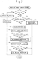
- FIG. 7 shows the routine for control of the supply of the reducing agent from the reducing agent supply valve 13. This routine is executed by interruption every certain time period.
- step 100 it is judged if the temperature TC of the NO x storing catalyst 11 is lower than the temperature setting Ts, for example, 200°C.
- Ts temperature setting
- the routine proceeds to step 101, where NO 2 ratio increase processing is performed for increasing the ratio of NO 2 in the exhaust gas (amount of NO 2 /amount of NO).
- the ratio of the NO 2 in the exhaust gas is increased by at least one of delay of the fuel injection timing, increase of the amount of EGR gas, pilot injection, or premix combustion.
- the majority of the NO x contained in the exhaust gas can be stored in the NO x storing catalyst 11 and therefore even in the interval after engine startup until the NO x storing catalyst 11 is activated, the release of a large amount of NO x into the atmosphere can be prevented.
- step 102 when the temperature TC of the NO x storing catalyst 11 exceeds the temperature setting Ts, the cumulative value ⁇ NOX of the NO x absorption amount is made the allowable value NX for the NO x release processing for releasing the NO x from the NO x absorbent 47 immediately.
- step 100 when it is judged at step 100 that TC ⁇ Ts, that is, when it is judged that the NO x storing catalyst 11 has become activated, the routine proceeds to step 103, where it is judged if the ignition switch 43 has been switched from on to off to stop the engine.
- step 104 the NO x absorption amount NOXA per unit time and the NO x absorption rate KN shown in FIG. 5B are calculated from the map shown in FIG. 5A.
- step 105 the actual NO x absorption amount KN ⁇ NOXA is added to ⁇ NOX so as to calculate the cumulative value ⁇ NOX of the amount of NO x absorption.
- step 106 it is judged if the cumulative value ⁇ NOX of the amount of NO x absorption has exceeded the allowable value NX.
- the routine jumps to step 108.
- the routine proceeds to step 107, where the NO x release processing I is performed, then the routine proceeds to step 108.
- the routine proceeds to step 107, where the NO x release processing I is performed.
- the value kS ⁇ Q of the fuel injection amount Q multiplied by the constant kS is added to ⁇ SOX.
- fuel contains a certain amount of sulfur. Therefore, the amount of SO x absorbed in the NO x absorbent 47 of the NO x storing catalyst 11 per unit time can be expressed by kS ⁇ Q. Accordingly, the ⁇ SOX obtained by adding to the ⁇ SOX to kS ⁇ Q expresses the cumulative value of the amount of SO x absorbed in the NO x absorbent 47.
- step 109 it is judged if the cumulative value ⁇ SOX of the amount of SO x exceeds the allowable value SX.
- the processing cycle is ended, while when ⁇ SOX>SX, the routine proceeds to step 110, where the SO x release processing is performed.
- step 103 when it is judged at step 103 that the ignition switch 43 has been switched from on to off, the routine proceeds to step 111, where NO x release processing II is performed for making the NO x amount absorbed in the NO x absorbent 4 zero.
- FIG. 8 shows the processing routine of the NO x release processing I executed at step 10 of FIG. 7.
- step 120 the amount of supply of the reducing agent required for making the air-fuel ratio of the exhaust gas a rich air-fuel ratio of about 13 is calculated.
- step 121 the supply time of the reducing agent is calculated.
- the supply time of the reducing agent is normally not more than 10 seconds.
- step 123 it is judged if the supply time of the reducing agent calculated at step 121 has elapsed. When the supply time of the reducing agent has not elapsed, the routine returns to step 123.
- the routine proceeds to step 124, where the supply of the reducing agent is stopped, then the routine proceeds to step 125, where the ⁇ NOX is cleared. Next, the routine proceeds to step 108 of FIG. 7.
- FIG. 9 shows the processing routine of the SO x release processing executed at step 110 of FIG. 7.
- control for raising the temperature of the NO x storing catalyst 11 is performed. That is, the fuel injection pattern from the fuel injector 3 is changed to any injection pattern shown in (II) to (IV) of FIG. 4.
- the fuel injection pattern is changed to any injection pattern from (II) to (IV) of FIG. 4
- the exhaust gas temperature rises and therefore the temperature of the NO x storing catalyst 11 rises.
- the routine proceeds to step 131, where it is judged if the temperature TC of the NO x storing catalyst 11 has become more than the SO x release temperature TX.
- TX the routine returns to step 131.
- step 132 the routine proceeds to step 132, where the amount of supply of the reducing agent required for making the air-fuel ratio of the exhaust gas a rich air-fuel ratio of about 14 is calculated.
- step 133 the supply time of the reducing agent is calculated.
- the supply time of the reducing agent is about 10 minutes.
- step 134 the supply of the reducing agent from the reducing agent supply valve 13 is started.
- step 135 it is judged if the supply time of the reducing agent calculated at step 133 has elapsed. When the supply time of the reducing agent has not elapsed, the routine returns to step 135.
- the routine proceeds to step 136, where the supply of the reducing agent is stopped.
- step 137 the temperature raising action of the NO x storing catalyst 11 is stopped, then the routine proceeds to step 138, where the ⁇ SOX and ⁇ NOX are cleared.
- FIG. 10 shows the processing routine of the NO x release processing II executed at step 111 of FIG. 7.
- step 140 the supply of reducing agent required for making the air-fuel ratio of the exhaust gas a rich air-fuel ratio of about 13 is calculated.
- step 141 the supply time of the reducing agent is calculated.
- the supply time of the reducing agent is usually not more than 10 seconds.
- step 142 the supply of the reducing agent from the reducing agent supply valve 13 is started.
- step 143 it is judged if the supply time of the reducing agent calculated at step 141 has elapsed or not. When the supply time of the reducing agent has not elapsed, the routine returns to step 143.
- step 144 the supply of the reducing agent is stopped
- step 145 the ⁇ NOX is cleared.
- step 146 processing is performed for stopping the engine.
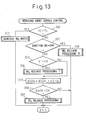
- FIG. 11 to FIG. 13 show a second embodiment.
- a NO x concentration sensor 22 able to detecting the NO x concentration in the exhaust gas is arranged in the exhaust pipe 21 attached to the outlet of the casing 12 housing the NO x storing catalyst 11 as shown in FIG. 11.
- This NO x concentration sensor 22 generates an output voltage V proportional to the NO x concentration as shown in FIG. 12B.
- the amount of absorbed NO x of the NO x absorbent 47 can be estimated from the NO x concentration in the exhaust gas.
- the amount of absorbed NO x estimated from the NO x concentration in the exhaust gas exceeds a predetermined allowable value, that is, as shown in FIG. 12A when the output voltage V of the NO x concentration sensor 22 exceeds the set value VX, the air-fuel ratio of the exhaust gas is switched from lean to rich.
- FIG. 13 shows the routine for control of the supply of the reducing agent from the reducing agent supply valve 13 in this embodiment.
- This routine is executed by interruption every constant time period.
- step 200 it is judged if the temperature TC of the NO x storing catalyst 11 is lower than the temperature setting Ts, for example, 200°C.
- Ts temperature setting
- the routine proceeds to step 201, where the NO 2 ratio increase processing is performed for increasing the ratio of the NO 2 in the exhaust gas (amount of NO 2 /amount of NO).
- the ratio of the NO 2 in the exhaust gas is increased by at least one of delay of the fuel injection timing, increase of the amount of EGR gas, pilot injection, or premix combustion.
- step 200 when it is judged that TC ⁇ Ts at step 200, that is, when it is judged that the NO x storing catalyst 11 has been activated, the routine proceeds to step 202, where it is judged if the ignition switch 43 has been switched from on to off to stop the engine.
- step 203 When the ignition switch 43 is still in the on position, the routine proceeds to step 203, where it is judged if the output voltage V of the NO x concentration sensor 22 exceeds the set value VX.
- V ⁇ VX the routine jumps to step 205.
- V>VX the routine proceeds to step 204, where the NO x release processing I shown in FIG. 8 is executed. Next, the routine proceeds to step 205.
- the value kS ⁇ Q of the fuel injection amount Q multiplied by the constant kS is added to ⁇ SOX.
- fuel contains a certain amount of sulfur. Therefore, the amount of SO x absorbed in the NO x absorbent 47 of the NO x storing catalyst 11 per unit time can be expressed by kS ⁇ Q. Therefore, the ⁇ SOX obtained by adding ⁇ SOX to kS ⁇ Q expresses the cumulative value of the amount of SO x absorbed in the NO x absorbent 47.
- the processing cycle is ended, while when ⁇ SOX>SX, the routine proceeds to step 207, where the SO x release processing shown in FIG. 9 is performed.
- step 202 when it is judged at step 202 that the ignition switch 43 has been switched from on to off, the routine proceeds to step 208, where the NO x release processing II shown in FIG. 10 is executed to make the NO x amount absorbed in the NO x absorbent 47 zero.
- FIGS. 14A and 14B show the structure of this particulate filter 11.
- FIG. 14A is a front view of the particulate filter 11
- FIG. 14B is a side sectional view of the particulate filter 11.
- the particulate filter 11 has a honeycomb structure and is provided with a plurality of exhaust gas flow passages 60 and 61 extending in parallel with each other. These exhaust flow passages are comprised of exhaust gas inflow passages 60 blocked at their downstream ends by plugs 62 and exhaust gas outflow passages 61 blocked at their upstream ends by plugs 63. Note that in FIG.
- the hatched portions show the plugs 63. Therefore, the exhaust gas inflow passages 60 and the exhaust gas outflow passages 61 are alternately arranged through thin partitions 64. In other words, the exhaust gas inflow passages 60 and the exhaust gas outflow passages 61 are arranged so that each exhaust gas inflow passage 60 is surrounded by four exhaust gas outflow passages 61 and each exhaust gas outflow passage 61 is surrounded by four exhaust gas inflow passages 60.
- the particulate filter 11 is formed from a porous material such as cordierite. Therefore, the exhaust gas flowing into the exhaust gas inflow passages 60 flows out through the surrounding partitions 64 to the insides of the adjoining exhaust gas outflow passages 61 as shown by the arrows in FIG. 14B.
- a layer of a catalyst carrier comprised of alumina is formed on the peripheral walls of the exhaust gas inflow passages 60 and the exhaust gas outflow passages 61, that is, the two side surfaces of the partitions 64 and the inside wall surfaces of the pores of the partitions 64.
- the precious metal catalyst 46 and the NO x absorbent 47 are carried on the catalyst carrier 45.
- platinum Pt is used as the precious metal catalyst.
- NO x and SO x release control is performed in the same way as the NO x and SO x release control for the NO x storing catalyst 11 shown from FIG. 7 to FIG. 11.
- the particulate contained in the exhaust gas is trapped in the particulate filter 11.
- the trapped particulate is successively burned by the heat of the exhaust gas. If a large amount of particulate deposits on the particulate filter 11, the injection pattern is switched to any one of the injection patterns (II) to (IV) of FIG. 4 or reducing agent is supplied from the reducing agent supply valve 13, whereby the exhaust gas temperature is raised and the deposited particulate is ignited and burned.
- FIG. 15 shows another embodiment.
- an oxidization catalyst 23 carrying a precious metal catalyst such as platinum Pt is arranged in the engine exhaust passage upstream of the NO x storing catalyst 11.
- This oxidation catalyst 23 does not carry a strongly basic NO x absorbent, so has a strong oxidation ability. Therefore, the oxidation action of nitrogen monoxide NO by the oxidation catalyst 23 is started from before the NO x storing catalyst 11 becomes active. That is, in this embodiment, the oxidation action of oxidizing the nitrogen monoxide NO into nitrogen dioxide NO 2 by the oxidation catalyst 23 before the NO x storing catalyst 11 becomes active. Therefore, in this embodiment, there is the advantage that the ratio of the NO 2 in the exhaust gas flowing into the NO x storing catalyst 11 can be raised.
- the amount of production of smoke peaks when the EGR rate becomes slightly lower than 50 percent. In this case, if the EGR rate is made at least about 55 percent, almost no smoke will be produced any longer.
- the curve B of FIG. 16 when cooling the EGR gas a little, the amount of production of smoke peaks when the EGR rate becomes slightly higher than 50 percent. In this case, if the EGR rate is made at least about 65 percent, almost no smoke will be produced any longer.
- the curve C of FIG. 16 if not force cooling the EGR gas, the amount of production of smoke peaks when the EGR rate is near 55 percent. In this case, if the EGR rate is made at least about 70 percent, almost no smoke will be produced any longer.
- This low temperature combustion has the feature of being able to suppress the production of smoke regardless of the air-fuel ratio while reducing the amount of production of NO x . That is, if the air-fuel ratio is made rich, the fuel will become excessive, but the combustion temperature is suppressed to a low temperature, so the excessive fuel will not grow into soot and therefore smoke will not be produced. Further, at this time, only a very small amount of NO x will be produced.
- FIGS. 17A and 17B show the relationship between the average gas temperature Tg in the combustion chambers 2 and the crank angle at the time of low temperature combustion, while the broken line in FIG. 17A shows the relationship between the average gas temperature Tg in the combustion chambers 2 and the crank angle at the time of ordinary combustion. Further, the solid line in FIG. 17B shows the relationship between the fuel and surrounding gas temperature Tf and the crank angle at the time of low temperature combustion, while the broken line in FIG. 17B shows the relationship between the fuel and surrounding gas temperature Tf and the crank angle at the time of ordinary combustion.
- the amount of EGR gas becomes greater than when ordinary combustion is being performed. Therefore, as shown in FIG. 17A, before compression top dead center, that is, during the compression stroke, the average gas temperature Tg at the time of low temperature combustion shown by the solid line becomes higher than the average gas temperature Tg at the time of ordinary combustion. Note that at this time, as shown by FIG. 17B, the fuel and surrounding gas temperature Tf becomes about the same temperature as the average gas temperature Tg.
- the average gas temperature Tg in the combustion chambers 2 near compression top dead center becomes higher in the case of ordinary combustion compared with the case of low temperature combustion.
- the temperature of the burned gas in the combustion chambers 2 after the end of combustion becomes higher in the case of low temperature combustion compared with the case of ordinary combustion and therefore if low temperature combustion is performed, the temperature of the exhaust gas becomes higher.
- the region I shows the operating region where first combustion with a larger amount of inert gas in the combustion chambers than the amount of inert gas where the production of soot peaks, that is, low temperature combustion, can be performed
- the region II shows the operating region where second combustion with a smaller amount of inert gas in the combustion chambers than the amount of inert gas where the production of soot peaks, that is, only combustion, can be performed.
- FIG. 19 shows the target air-fuel ratio A/F in the case of low temperature combustion in the operating region I
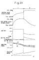
- FIG. 20 shows the opening degree of the throttle valve 9, the opening degree of the EGR control valve 15, the EGR rate, the air-fuel ratio, the injection start timing ⁇ S, the injection end timing ⁇ E, and the injection amount in accordance with the required torque TQ in the case of low temperature combustion in the operating region I.
- FIG. 20 also shows the opening degree of the throttle valve 9 etc. at the time of ordinary combustion performed in the operating region II.
- the ratio of the NO 2 in the exhaust gas is increased by performing slow combustion after engine startup.
- the atmospheric temperature inside the combustion chambers 2 will fall from the expansion stroke to the exhaust stroke. Therefore, even if maintaining the temperature of the inside wall surfaces of the combustion chambers 2 at a low temperature in this way, the ratio of the NO 2 in the exhaust gas can be increased.
- FIG. 21 to FIG. 23 show various embodiments for increasing the ratio of NO 2 in the exhaust gas by maintaining the temperature of the inside wall surfaces of the combustion chambers 2 at a low temperature after engine startup.
- 70 is an engine-driven water pump, 71 a radiator, 72 a valve for controlling the flow of engine cooling water, and 24 a water temperature sensor for detecting the engine cooling water temperature.
- the valve 72 When opening the valve 72 at the time of engine operation, the high temperature engine cooling water is sent from the engine body 1 through the conduit 73 to the radiator 71 to be cooled, then the cooled engine cooling water is returned through the conduit 74, the valve 72, and the water pump 70 to the inside of the engine body 1.
- valve 72 is made to close and the cooling action of the engine cooling water by the radiator 71 is stopped to promote the engine warmup.
- the valve 72 is immediately made to open so as to start the cooling action of the engine cooling water by the radiator 71 and thereby maintain the temperature of the inside wall surfaces of the combustion chambers 2 at a low, temperature and increase the ratio of the NO 2 in the exhaust gas.
- 75 indicates an engine-driven oil pump, 76 an oil cooler, 77 a valve controlling the flow of the engine cooling water, and 25 an oil temperature sensor for detecting the engine oil temperature.
- the valve 77 opens at the time of engine operation, the high temperature engine oil is sent from the engine body 1 through the conduit 78 to the oil cooler 76 and cooled, then the cooled engine oil is returned through the conduit 79, valve 77, and oil pump 75 to the inside of the engine body 1.
- valve 77 is made to close and the cooling action of the engine oil by the oil cooler 76 is stopped to promote the engine warmup.
- the valve 77 is immediately made to open so as to start the cooling action of the engine oil by the oil cooler 76 and thereby maintain the temperature of the inside wall surfaces of the combustion chambers 2 at a low temperature and increase the ratio of the NO 2 in the exhaust gas.
- the temperature of the inside wall surfaces of the combustion chambers 2 is maintained at a low temperature, if the NO x storing catalyst 11 is activated, the ratio of the NO 2 in the exhaust gas will no longer have to be increased. Further, at this time, it will be necessary to end the engine warmup quickly. Therefore, in this embodiment, when the temperature of the inside wall surfaces of the combustion chambers 2 is maintained at a low temperature, when the NO x storing catalyst 11 is activated, the cooling action of the engine oil by the oil cooler 76 is stopped. When the engine warmup is then completed, the cooling action of the engine oil by the oil cooler 76 is again started.
- the embodiment shown in FIG. 23 arranges the oil cooler 76 inside the conduit 74 of the embodiment shown in FIG. 21 and cools the oil cooler 76 by the engine cooling water.
- This oil cooler 76 is constantly run through by engine oil.
- the valve 72 is closed and the cooling action of the engine cooling water by the radiator 71 is stopped, the cooling action of the engine oil by the oil cooler 76 is also stopped.
- the cooling action of the engine cooling water by the radiator 71 is started. Due to this, by starting the cooling action of the engine oil by the oil cooler 76, the temperature of the inside walls of the combustion chambers 2 is maintained at a low temperature and the ratio of the NO 2 in the exhaust gas is increased. On the other hand, when maintaining the temperature of the inside walls of the combustion chambers 2 at a low temperature, when the NO x storing catalyst 11 is activated, the cooling action of the engine cooling water by the radiator 71 is stopped. When the engine warmup is then completed, the cooling action of the engine cooling water by the radiator 71 is again started.
- FIG. 24 shows a time interruption routine for increasing the ratio of NO 2 in the embodiment shown in FIG. 21 and FIG. 23.
- step 300 it is judged if the temperature TC of the NO x storing catalyst 11 exceeds the temperature setting Ts, that is, if the NO x storing catalyst 11 is activated.
- the routine proceeds to step 301, where the valve 72 is opened, whereby the cooling action of the engine cooling water by the radiator 71 is performed.
- the routine jumps to step 302.
- step 302 it is judged if TC ⁇ Ts, that is, if the NO x storing catalyst 11 is activated and the engine cooling water temperature TW is lower than the temperature setting Tr, for example, 80°C, that is, if the engine warmup has not been completed.
- Tr temperature setting
- the routine proceeds to step 303, where the valve 72 is closed, whereby the cooling action of the engine cooling water by the radiator 71 is stopped.
- the routine jumps to step 304.
- step 304 it is judge if TC ⁇ Ts, that is, if the NO x storing catalyst 11 is activated and the engine cooling water temperature TW is higher than the temperature setting Tr, for example, that is, if engine warmup has been completed.
- the routine proceeds to step 305, where the valve 72 is opened, whereby the cooling action of the engine cooling water by the radiator 71 is restarted.
- the processing cycle is ended.
- FIG. 25 shows a time interruption routine for increasing the ratio of NO 2 in the embodiment shown in FIG. 22.
- step 400 it is judged if the temperature TC of the NO x storing catalyst 11 exceeds the temperature setting Ts, that is, if the NO x storing catalyst 11 is activated.
- Ts the temperature setting
- the routine proceeds to step 401, where the valve 77 is opened, whereby the cooling action of the engine oil by the oil cooler 76 is performed.
- the routine jumps to step 402.
- step 402 it is judged if TC ⁇ Ts, that is, if the NO x storing catalyst 11 is activated and the engine oil temperature TO is lower than the temperature setting Tz, for example, 80°C, that is, if the engine warmup has not been completed.
- Tz temperature setting
- the routine proceeds to step 403, where the valve 77 is closed, whereby the cooling action of the engine oil by the oil cooler 76 is stopped.
- the routine jumps to step 404.
- step 404 it is judge if TC ⁇ Ts, that is, if the NO x storing catalyst 11 is activated and the engine oil temperature TO is higher than the temperature setting Tz, that is, if engine warmup has been completed.
- the routine proceeds to step 405, where the valve 77 is opened, whereby the cooling action of the engine oil by the oil cooler 76 is restarted.
- the processing cycle is ended.
Landscapes
- Engineering & Computer Science (AREA)
- Chemical & Material Sciences (AREA)
- Combustion & Propulsion (AREA)
- Mechanical Engineering (AREA)
- General Engineering & Computer Science (AREA)
- Chemical Kinetics & Catalysis (AREA)
- Exhaust Gas After Treatment (AREA)
- Processes For Solid Components From Exhaust (AREA)
- Electrical Control Of Air Or Fuel Supplied To Internal-Combustion Engine (AREA)
- Combined Controls Of Internal Combustion Engines (AREA)
Abstract
Description
Claims (19)
- An exhaust purification device comprising:a NOx storing catalyst comprised of a precious metal catalyst and a NOx absorbent and arranged in an engine exhaust passage, said NOx absorbent storing nitrogen dioxide NO2 contained in the exhaust gas when an air-fuel ratio of exhaust gas flowing into said NOx storing catalyst is lean when said NOx storing catalyst is not activated, said NOx absorbent storing nitrogen oxides NOx contained in exhaust gas when the air-fuel ratio of the exhaust gas flowing into the NOx storing catalyst is lean when said NOx storing catalyst is activated, said NOx absorbent releasing stored nitrogen oxides NOx when the air-fuel ratio of the exhaust gas flowing into the NOx storing catalyst becomes the stoichiometric air-fuel ratio or rich;NO2 ratio increasing means for increasing a ratio of nitrogen dioxide NO2 with respect to nitrogen monoxide NO produced when burning fuel under a lean air-fuel ratio when the NOx storing catalyst is not activated compared with the time when the NOx storing catalyst is activated under the same engine operating conditions; andair-fuel ratio switching means for temporarily switching the air-fuel ratio of the exhaust gas flowing into the NOx storing catalyst cyclically from lean to the stoichiometric air-fuel ratio or rich so as to release NOx from the NOx absorbent when the NOx storing catalyst is activated.
- An exhaust purification device as set forth in claim 1, wherein said NO2 ratio increasing means performs slow combustion when said NOx storing catalyst is not activated compared with when said NOx storing catalyst is activated under the same engine operating conditions.
- An exhaust purification device as set forth in claim 2, wherein said slow combustion is performed by at least one of delaying a fuel injection timing, increasing an amount of exhaust gas recirculation gas, pilot injection, and premix combustion.
- An exhaust purification device as set forth in claim 1, wherein said NO2 ratio increasing means increases the ratio of nitrogen dioxide NO2 with respect to nitrogen monoxide NO after engine startup to activation of the NOx storing catalyst and stops the action of increasing said ratio when said NOx storing catalyst is activated.
- An exhaust purification device as set forth in claim 1, wherein said NO2 ratio increasing means starts a cooling action of engine cooling water by a radiator right after engine startup when said NOx storing catalyst is not activated.
- An exhaust purification device as set forth in claim 5, wherein said NO2 ratio increasing means stops said cooling action of engine cooling water by the radiator when the temperature of the engine cooling water is lower than a temperature setting when said NOx storing catalyst is activated.
- An exhaust purification device as set forth in claim 5, wherein engine oil is cooled by said engine cooling water.
- An exhaust purification device as set forth in claim 1, wherein said NO2 ratio increasing means starts a cooling action of engine oil by an oil cooler right after engine startup when said NOx storing catalyst is not activated.
- An exhaust purification device as set forth in claim 8, wherein said NO2 ratio increasing means stops said cooling action of engine oil by the oil cooler when the temperature of the engine oil is lower than a temperature setting when said NOx storing catalyst is activated.
- An exhaust purification device as set forth in claim 1, wherein said air-fuel ratio switching means temporarily switches an air-fuel ratio of exhaust gas flowing to said NOx storing catalyst from lean to the stoichiometric air-fuel ratio or rich immediately to release NOx from said NOx absorbent when said NOx storing catalyst is activated after engine startup.
- An exhaust purification device as set forth in claim 1, wherein said air-fuel ratio switching means temporarily switches an air-fuel ratio of exhaust gas flowing into said NOx storing catalyst from lean to the stoichiometric air-fuel ratio or rich to release NOx from said NOx absorbent when stopping engine operation.
- An exhaust purification device as set forth in claim 1, wherein said device further comprises means for estimating the amount NOx absorbed in said NOx absorbent and said air-fuel ratio of said exhaust gas is switched from lean to rich when the estimated amount of NOx absorption exceeds a predetermined allowable value.
- An exhaust purification device as set forth in claim 12, wherein said device further comprises a NOx concentration sensor for detecting a concentration of NOx in exhaust gas flowing out from said NOx storing catalyst and it is judged that the amount of NOx absorption of said NOx absorbent has exceeded the allowable value when the NOx concentration detected by said NOx concentration sensor exceeds a setting.
- An exhaust purification device as set forth in claim 1, wherein when releasing SOx absorbed in the NOx absorbent of said NOx storing catalyst from said NOx absorbent, the temperature of the NOx storing catalyst is raised to a SOx release temperature, then the temperature of the NOx storing catalyst is maintained at the SOx release temperature while the air-fuel ratio of the exhaust gas is made rich.
- An exhaust purification device as set forth in claim 1, wherein said NOx storing catalyst is comprised of a particulate filter.
- An exhaust purification device as set forth in claim 1, wherein the air-fuel ratio of the exhaust gas is made rich by supplying a reducing agent into the engine exhaust passage.
- An exhaust purification device as set forth in claim 1, wherein said engine is one where when the amount of exhaust gas recirculation is increased, the amount of soot produced gradually increases and then peaks and when the amount of exhaust gas recirculation is further increased, soot is no longer generated much at all and where the air-fuel ratio in the combustion chambers is made rich in the state where the amount of exhaust gas recirculation is increased over the amount where the amount of production of soot peaks so as to make the air-fuel ratio of the exhaust gas rich.
- An exhaust purification device as set forth in claim 1, wherein said engine is one where when the amount of exhaust gas recirculation is increased, the amount of soot produced gradually increases and then peaks and when the amount of exhaust gas recirculation is further increased, soot is no longer generated much at all and where the amount of exhaust gas recirculation is increased over the amount where the amount of production of soot peaks when the temperature of the NOx storing catalyst should be raised.
- An exhaust purification method of an internal combustion engine comprising:using a NOx storing catalyst comprised of a precious metal catalyst and a NOx absorbent as a catalyst for purifying NOx in exhaust gas;increasing a ratio of nitrogen dioxide NO2 with respect to nitrogen monoxide NO produced when burning fuel under a lean air-fuel ratio when said NOx storing catalyst is not activated compared with when said NOx storing catalyst is activated under the same engine operating conditions;storing said nitrogen dioxide NO2 contained in the exhaust gas in said NOx absorbent at that time;changing nitrogen dioxide NO2 stored in said NOx absorbent to nitric acid ions NO3 - when the temperature of said NOx storing catalyst rises;cyclically temporarily switching the air-fuel ratio of the exhaust gas flowing into the NOx storing catalyst from lean to the stoichiometric air-fuel ratio or rich when said NOx storing catalyst is activated; and therebyreleasing nitrogen oxides NOx stored in the NOx absorbent in the form of nitric acid ions NO3 - from the NOx absorbent.
Applications Claiming Priority (4)
| Application Number | Priority Date | Filing Date | Title |
|---|---|---|---|
| JP2003172072 | 2003-06-17 | ||
| JP2003172072 | 2003-06-17 | ||
| JP2003427779A JP4158697B2 (en) | 2003-06-17 | 2003-12-24 | Exhaust gas purification device and exhaust gas purification method for internal combustion engine |
| JP2003427779 | 2003-12-24 |
Publications (2)
| Publication Number | Publication Date |
|---|---|
| EP1489288A2 true EP1489288A2 (en) | 2004-12-22 |
| EP1489288A3 EP1489288A3 (en) | 2005-06-15 |
Family
ID=33422161
Family Applications (1)
| Application Number | Title | Priority Date | Filing Date |
|---|---|---|---|
| EP04013976A Withdrawn EP1489288A3 (en) | 2003-06-17 | 2004-06-15 | Method and device for exhaust purification of an internal combustion engine |
Country Status (3)
| Country | Link |
|---|---|
| US (1) | US7146800B2 (en) |
| EP (1) | EP1489288A3 (en) |
| JP (1) | JP4158697B2 (en) |
Cited By (3)
| Publication number | Priority date | Publication date | Assignee | Title |
|---|---|---|---|---|
| DE102007032734A1 (en) * | 2007-07-13 | 2009-01-15 | Emitec Gesellschaft Für Emissionstechnologie Mbh | Process for the regeneration of at least one particle agglomerator and motor vehicle comprising an exhaust aftertreatment system |
| EP2503120A4 (en) * | 2011-02-10 | 2014-08-27 | Toyota Motor Co Ltd | EXHAUST GAS PURIFYING DEVICE FOR INTERNAL COMBUSTION ENGINE |
| GB2565423A (en) * | 2017-06-23 | 2019-02-13 | Toyota Motor Co Ltd | Exhaust gas control apparatus for internal combustion engine |
Families Citing this family (28)
| Publication number | Priority date | Publication date | Assignee | Title |
|---|---|---|---|---|
| US7565799B2 (en) * | 2005-02-09 | 2009-07-28 | Gm Global Technology Operations, Inc. | Controlling lean NOx trap (LNT) catalyst performance |
| DE102005049655A1 (en) * | 2005-10-18 | 2007-04-19 | Man Nutzfahrzeuge Ag | Preventing unwanted nitrogen dioxide emission from combustion engines involves adapting engine operating point and catalyzer state so only nitrogen dioxide required for exhaust gas treatment is present in exhaust gas downstream of catalyzer |
| US7467605B2 (en) * | 2006-05-26 | 2008-12-23 | Visteon Global Technologies, Inc. | Thermal energy recovery and management system |
| KR101383422B1 (en) | 2010-03-15 | 2014-04-08 | 도요타지도샤가부시키가이샤 | Exhaust purification system of internal combustion engine |
| ES2508365T3 (en) | 2010-03-15 | 2014-10-16 | Toyota Jidosha Kabushiki Kaisha | Method of operation of an exhaust gas purification system of an internal combustion engine |
| JP5196027B2 (en) | 2010-04-01 | 2013-05-15 | トヨタ自動車株式会社 | Exhaust gas purification device for internal combustion engine |
| WO2012014330A1 (en) | 2010-07-28 | 2012-02-02 | トヨタ自動車株式会社 | Exhaust purification apparatus for internal combustion engine |
| EP2460990B8 (en) | 2010-08-30 | 2016-12-07 | Toyota Jidosha Kabushiki Kaisha | Exhaust gas purification device for internal combustion engine |
| CN103003539B (en) | 2010-08-30 | 2015-03-18 | 丰田自动车株式会社 | Exhaust gas purification device for internal combustion engine |
| US9034267B2 (en) | 2010-10-04 | 2015-05-19 | Toyota Jidosha Kabushiki Kaisha | Exhaust purification system of internal combustion engine |
| EP2472078B1 (en) | 2010-10-04 | 2018-05-16 | Toyota Jidosha Kabushiki Kaisha | An exhaust purification system of an internal combustion engine |
| WO2012053117A1 (en) | 2010-10-18 | 2012-04-26 | トヨタ自動車株式会社 | Exhaust gas purification device for internal combustion engine |
| WO2012077240A1 (en) | 2010-12-06 | 2012-06-14 | トヨタ自動車株式会社 | Exhaust gas purification device for internal combustion engine |
| BRPI1010835B8 (en) | 2010-12-20 | 2021-01-12 | Toyota Motor Co Ltd | internal combustion engine exhaust purification system |
| ES2629430T3 (en) | 2010-12-24 | 2017-08-09 | Toyota Jidosha Kabushiki Kaisha | Exhaust gas purification system for internal combustion engine |
| WO2012108059A1 (en) | 2011-02-07 | 2012-08-16 | トヨタ自動車株式会社 | Exhaust-gas purifying device for internal-combustion engine |
| WO2012124173A1 (en) | 2011-03-17 | 2012-09-20 | トヨタ自動車株式会社 | Internal combustion engine exhaust gas purification device |
| WO2012140784A1 (en) | 2011-04-15 | 2012-10-18 | トヨタ自動車株式会社 | Exhaust cleaner for internal combustion engine |
| CN103998731B (en) | 2011-11-07 | 2016-11-16 | 丰田自动车株式会社 | The emission-control equipment of internal combustion engine |
| US9097157B2 (en) | 2011-11-09 | 2015-08-04 | Toyota Jidosha Kabushiki Kaisha | Exhaust purification system of internal combustion engine |
| WO2013080328A1 (en) | 2011-11-30 | 2013-06-06 | トヨタ自動車株式会社 | Exhaust purification device for internal combustion engine |
| JP5273304B1 (en) | 2011-11-30 | 2013-08-28 | トヨタ自動車株式会社 | Exhaust gas purification device for internal combustion engine |
| ES2629482T3 (en) | 2012-02-07 | 2017-08-10 | Toyota Jidosha Kabushiki Kaisha | Exhaust gas purification device for internal combustion engine |
| US9145823B2 (en) * | 2012-10-19 | 2015-09-29 | Ford Global Technologies, Llc | Method for purging condensate from a charge air cooler |
| JP6172018B2 (en) * | 2014-03-27 | 2017-08-02 | マツダ株式会社 | Compression ignition engine starter |
| JP6551312B2 (en) * | 2016-06-02 | 2019-07-31 | 株式会社デンソー | Reductant addition control device |
| CN111828148B (en) * | 2019-04-15 | 2021-10-26 | 康明斯排放处理公司 | System and method for detecting incomplete purge events |
| CN114109569B (en) * | 2020-09-01 | 2023-01-31 | 长城汽车股份有限公司 | Exhaust gas cleaning device and method for preventing irrecoverable sulfur poisoning in LNT area |
Family Cites Families (17)
| Publication number | Priority date | Publication date | Assignee | Title |
|---|---|---|---|---|
| JP2845052B2 (en) | 1992-09-28 | 1999-01-13 | トヨタ自動車株式会社 | Exhaust gas purification device for internal combustion engine |
| JP3287082B2 (en) | 1993-11-15 | 2002-05-27 | トヨタ自動車株式会社 | Exhaust gas purification device for internal combustion engine |
| JP3899534B2 (en) * | 1995-08-14 | 2007-03-28 | トヨタ自動車株式会社 | Exhaust gas purification method for diesel engine |
| JPH1071325A (en) * | 1996-06-21 | 1998-03-17 | Ngk Insulators Ltd | Method for controlling engine exhaust gas system and method for detecting deterioration in catalyst/ adsorption means |
| EP0925431B1 (en) | 1996-09-05 | 2004-08-25 | Volkswagen Aktiengesellschaft | Exhaust fume purification process for an internal combustion engine |
| DE19645689B4 (en) | 1996-11-06 | 2006-05-11 | Bayerische Motoren Werke Ag | Device for exhaust aftertreatment for an internal combustion engine, in particular Otto engine with lean operation |
| JP4034375B2 (en) | 1997-04-03 | 2008-01-16 | トヨタ自動車株式会社 | Exhaust gas purification device for internal combustion engine |
| JP3451902B2 (en) | 1997-10-03 | 2003-09-29 | 株式会社日立製作所 | Control method of NOx catalyst |
| EP0982486B1 (en) | 1998-07-21 | 2008-10-01 | Toyota Jidosha Kabushiki Kaisha | Internal combustion engine |
| JP3228232B2 (en) * | 1998-07-28 | 2001-11-12 | トヨタ自動車株式会社 | Exhaust gas purification device for internal combustion engine |
| US6775972B2 (en) * | 1998-10-09 | 2004-08-17 | Johnson Matthey Public Limited Company | Purification of exhaust gases |
| US6293096B1 (en) * | 1999-06-23 | 2001-09-25 | Southwest Research Institute | Multiple stage aftertreatment system |
| DE10003219A1 (en) | 2000-01-26 | 2001-08-02 | Volkswagen Ag | Method and device for controlling a NOx storage catalytic converter arranged in an exhaust gas duct of an internal combustion engine |
| DE10023439A1 (en) | 2000-05-12 | 2001-11-22 | Dmc2 Degussa Metals Catalysts | Process for removing nitrogen oxides and soot particles from the lean exhaust gas of an internal combustion engine and exhaust gas purification system therefor |
| JP2003138952A (en) | 2001-11-05 | 2003-05-14 | Mitsubishi Motors Corp | Diesel engine |
| US6912847B2 (en) * | 2001-12-21 | 2005-07-05 | Engelhard Corporation | Diesel engine system comprising a soot filter and low temperature NOx trap |
| US6964157B2 (en) | 2002-03-28 | 2005-11-15 | Ricardo, Inc | Exhaust emission control system and method for removal and storage of vehicle exhaust gas nitrogen oxides during cold operation |
-
2003
- 2003-12-24 JP JP2003427779A patent/JP4158697B2/en not_active Expired - Fee Related
-
2004
- 2004-06-14 US US10/865,875 patent/US7146800B2/en not_active Expired - Lifetime
- 2004-06-15 EP EP04013976A patent/EP1489288A3/en not_active Withdrawn
Cited By (4)
| Publication number | Priority date | Publication date | Assignee | Title |
|---|---|---|---|---|
| DE102007032734A1 (en) * | 2007-07-13 | 2009-01-15 | Emitec Gesellschaft Für Emissionstechnologie Mbh | Process for the regeneration of at least one particle agglomerator and motor vehicle comprising an exhaust aftertreatment system |
| EP2503120A4 (en) * | 2011-02-10 | 2014-08-27 | Toyota Motor Co Ltd | EXHAUST GAS PURIFYING DEVICE FOR INTERNAL COMBUSTION ENGINE |
| GB2565423A (en) * | 2017-06-23 | 2019-02-13 | Toyota Motor Co Ltd | Exhaust gas control apparatus for internal combustion engine |
| GB2565423B (en) * | 2017-06-23 | 2019-10-09 | Toyota Motor Co Ltd | Exhaust gas control apparatus for internal combustion engine |
Also Published As
| Publication number | Publication date |
|---|---|
| JP2005030380A (en) | 2005-02-03 |
| JP4158697B2 (en) | 2008-10-01 |
| EP1489288A3 (en) | 2005-06-15 |
| US7146800B2 (en) | 2006-12-12 |
| US20040255577A1 (en) | 2004-12-23 |
Similar Documents
| Publication | Publication Date | Title |
|---|---|---|
| US7146800B2 (en) | Exhaust purification device and exhaust purification method of internal combustion engine | |
| EP1685311B1 (en) | Exhaust purification device of compression ignition type internal combustion engine | |
| EP1148227B1 (en) | Exhaust gas purification device | |
| US6378297B1 (en) | Air-fuel control system for exhaust gas purification on ice | |
| EP1544429B1 (en) | Exhaust gas clarifying device for internal combustion engine | |
| EP1172532B1 (en) | Exhaust gas cleaning method | |
| EP1710407B1 (en) | Exhaust emission purification apparatus of compression ignition internal combustion engine | |
| EP2013455A1 (en) | Exhaust gas purification device for internal combustion engine | |
| CN100449123C (en) | Exhaust purification method and exhaust purification device of internal combustion engine | |
| EP2420655A1 (en) | Exhaust purification device for internal combustion engine | |
| JP4406309B2 (en) | Exhaust gas purification device for internal combustion engine | |
| EP1671016B1 (en) | Exhaust purification device and exhaust purification method of internal combustion engine | |
| JP4357917B2 (en) | Exhaust gas purification device for internal combustion engine | |
| JP3546950B2 (en) | Exhaust gas purification device for internal combustion engine | |
| JP3551797B2 (en) | Internal combustion engine | |
| JP2006336589A (en) | Exhaust gas purification device for internal combustion engine | |
| JP3580223B2 (en) | Exhaust gas purification device | |
| JP4003730B2 (en) | Exhaust gas purification device for internal combustion engine | |
| JP4254505B2 (en) | Exhaust gas purification device for internal combustion engine | |
| JP2010038116A (en) | Exhaust emission control device for internal combustion engine |
Legal Events
| Date | Code | Title | Description |
|---|---|---|---|
| PUAI | Public reference made under article 153(3) epc to a published international application that has entered the european phase |
Free format text: ORIGINAL CODE: 0009012 |
|
| 17P | Request for examination filed |
Effective date: 20040714 |
|
| AK | Designated contracting states |
Kind code of ref document: A2 Designated state(s): AT BE BG CH CY CZ DE DK EE ES FI FR GB GR HU IE IT LI LU MC NL PL PT RO SE SI SK TR |
|
| AX | Request for extension of the european patent |
Extension state: AL HR LT LV MK |
|
| PUAL | Search report despatched |
Free format text: ORIGINAL CODE: 0009013 |
|
| AK | Designated contracting states |
Kind code of ref document: A3 Designated state(s): AT BE BG CH CY CZ DE DK EE ES FI FR GB GR HU IE IT LI LU MC NL PL PT RO SE SI SK TR |
|
| AX | Request for extension of the european patent |
Extension state: AL HR LT LV MK |
|
| RIN1 | Information on inventor provided before grant (corrected) |
Inventor name: YOSHIDA, KOHEI Inventor name: NAKANO, YASUAKI Inventor name: ASANUMA, TAKAMITSU Inventor name: HIROTA, SHINYA Inventor name: TOSHIOKA, SHUNSUKE |
|
| AKX | Designation fees paid |
Designated state(s): DE FR GB |
|
| RAP1 | Party data changed (applicant data changed or rights of an application transferred) |
Owner name: TOYOTA JIDOSHA KABUSHIKI KAISHA |
|
| STAA | Information on the status of an ep patent application or granted ep patent |
Free format text: STATUS: THE APPLICATION IS DEEMED TO BE WITHDRAWN |
|
| 18D | Application deemed to be withdrawn |
Effective date: 20130820 |