EP1489033B2 - Elevator with two cars arranged one above the other in the same hoistway - Google Patents
Elevator with two cars arranged one above the other in the same hoistway Download PDFInfo
- Publication number
- EP1489033B2 EP1489033B2 EP04013309.2A EP04013309A EP1489033B2 EP 1489033 B2 EP1489033 B2 EP 1489033B2 EP 04013309 A EP04013309 A EP 04013309A EP 1489033 B2 EP1489033 B2 EP 1489033B2
- Authority
- EP
- European Patent Office
- Prior art keywords
- shaft
- counterweight
- guide rails
- drives
- elevator
- Prior art date
- Legal status (The legal status is an assumption and is not a legal conclusion. Google has not performed a legal analysis and makes no representation as to the accuracy of the status listed.)
- Not-in-force
Links
Images


Classifications
-
- B—PERFORMING OPERATIONS; TRANSPORTING
- B66—HOISTING; LIFTING; HAULING
- B66B—ELEVATORS; ESCALATORS OR MOVING WALKWAYS
- B66B11/00—Main component parts of lifts in, or associated with, buildings or other structures
- B66B11/0065—Roping
- B66B11/008—Roping with hoisting rope or cable operated by frictional engagement with a winding drum or sheave
- B66B11/0095—Roping with hoisting rope or cable operated by frictional engagement with a winding drum or sheave where multiple cars drive in the same hoist way
-
- B—PERFORMING OPERATIONS; TRANSPORTING
- B66—HOISTING; LIFTING; HAULING
- B66B—ELEVATORS; ESCALATORS OR MOVING WALKWAYS
- B66B9/00—Kinds or types of lifts in, or associated with, buildings or other structures
-
- B—PERFORMING OPERATIONS; TRANSPORTING
- B66—HOISTING; LIFTING; HAULING
- B66B—ELEVATORS; ESCALATORS OR MOVING WALKWAYS
- B66B19/00—Mining-hoist operation
- B66B19/007—Mining-hoist operation method for modernisation of elevators
Definitions
- the invention relates to a method for modernizing an elevator system according to the definition of the preamble of the claim.
- US5419414 shows an elevator system with several superimposed in a bay cabins.
- the cabins are moved independently.
- Each cabin has a drive and a counterweight.
- the cabins are connected via ropes as a conveyor with counterweights. So that all cabins can serve the same floors of the building, alternative rooms are provided above and below the floors served by the cabins.
- first cabins can move into these alternative spaces and further cabins can be moved to the place in the shaft of the first cabins.
- the drives are mounted above the shaft.
- a disadvantage of the teaching according to US5419414 is that the assembly of multiple drives in a machine room above the shaft is expensive. Such a machine room is often difficult to access. For example. The drives must be disassembled for transport into the engine room so that they pass through aisles and doors, which corridors and doors are on the way to the engine room. It is also disadvantageous that the presence of a machine room above the shaft and the provision of alternative spaces in the shaft keep the potentially usable building space low. In particular, floors that are at the height of the alternative rooms can not be served by the cabins. From these drawbacks follows that the re-installation and modernization of such a lift system causes high costs.
- WO02 / 030801 discloses an elevator installation with several cabins arranged one above the other in a shaft. The cabins are moved independently. For this purpose, each cabin has a drive placed in the shaft head. In the embodiments shown, two 1: 1 suspended cabs are associated with a single 2: 1 counterweight.
- the object of the invention is to provide an elevator system that is easy and inexpensive to install, which provides a high capacity and with an existing elevator system is easy and inexpensive to modernize.
- This elevator system should be compatible with existing and proven elevator manufacturing processes.
- the invention achieves this object with a method for modernizing an elevator installation, which is characterized in that at least two cabins arranged one above the other in the vertical travel direction are mounted in a shaft, with at least one cabin guide rail for guiding the cars, with one drive per booth which drives are arranged close to various first walls in the shaft, with conveying means for connecting the drives and cabins, with a counterweight per cabin, with at least one counterweight guide rail per counterweight, which counterweights and the counterweight guide rails close to the first walls in the Shaft are arranged, wherein the drives are arranged at substantially the same height in the shaft, and wherein at least one escape space is provided for at least one cabin, which escape space is arranged in the shaft head and / or in the shaft bottom and an existing engine room to at least ei An alternative space for at least one cabin is rebuilt.
- the drives are thus arranged in the shaft, for example in the shaft head.
- the engine room falls away, whereby the building space is used optimally and at the same time, by the use of at least two cabins in the same shaft, a significant increase in capacity occurs.
- An assembly of several drives in the shaft head is much easier to accomplish, than outside the shaft in the engine room.
- the components of the drives can be transported through the shaft in the shaft head.
- each drive of a car above the counterweight of that car is located close to the first walls in the manhole.
- At least one counterweight guide rail per counterweight is provided.
- the drives are supported on ends of the guide rails for cabin and counterweight.
- conveyor fixing points are fastened to the guide rails for the car or counterweight.
- an electrical system for the elevator is at least partially supported on the guide rails for the car or counterweight.
- the drives and / or the electrical system are supported directly or indirectly via horizontal beams of the guide rails for cabin or counterweight or the constructiveffenfixa are attached directly or indirectly via horizontal support on the guide rails for cabin or counterweight.
- the guide rails for cabin or counterweight or the horizontal support also form a self-supporting structure for supporting the drives, the cabins, the counterweight and the electrical system as well as for fixing the winning advicefixa.
- This structure is largely symmetrical and mirrored with respect to a diagonal of the shaft cross-section. Thus, no essential interface to the building is necessary, which simplifies the re-installation and assembly of the elevator system.
- the access to the cabins is via floor doors, which floor doors are arranged on second walls in the shaft, which second walls are different from the first walls.
- guide rails, counterweights and drives are mounted close to two first walls, while the floor doors are mounted on two second walls.
- At least one escape space is provided for at least one cabin, which alternative space is arranged in the shaft head and / or in the shaft floor.
- an existing engine room is converted into an alternative space for at least one car.
- a first cabin By providing at least one escape space above or below the served floors of the building, a first cabin can be moved into this escape space.
- This first cabin occupies now no more space in the shaft area of the served floors and a further cabin can be moved into this place.
- a further cabin can operate the floor below or above the outside space, in particular in the case of an impact operation leading to an increase in the delivery capacity.
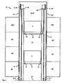
- the Fig. 1 to 4 show embodiments of an elevator installation 10 for transporting persons / goods between floors 10, 10 ', 10 ", 10'' ' of a building
- the elevator installation 10 is advantageously installed in a shaft 11 of the building, for example, the shaft has a rectangular cross-section
- the shaft 11 has various walls 111, 112, 113, 114, a shaft head 11 ' and a shaft bottom 11 " .
- the various walls 111, 112, 113, 114 are delimited by edges, which edges are, for example, rectangular and extend through the length of the shaft 11 .
- the shaft 11 may also have other cross-sectional shapes such as a hexagon with six different walls, it may also have a circular cross-section with several different wall areas.
- a circular shaft consists of four wall areas of 90 ° each or six wall areas of 60 °, etc.
- the shaft 11 may extend only partially through the building.
- the elevator installation 10 can be installed without a box in an inner courtyard of a building or else outside a building. The expert has many possibilities of variation here.
- the elevator installation 10 has at least two cabins 1, 1 ' , which cabins are moved one above the other in the vertical direction of travel in the shaft 11 .
- the term "movable one above the other” is understood to mean that the other car is not driven over, ie a lower car 1 always remains below an upper car 1 ' .
- the cabins 1, 1 ' are conventional and proven elevator cars, which are moved via guide shoes on at least one car guide rail 3, 3' .
- both cabins 1, 1 ' use two car guide rails 3, 3' close to different first walls 111, 112.
- a first car guide rail 3 is arranged close to a first wall 111 and a second car guide rail 3 ' is close arranged on a further first wall 112 .
- the elevator installation 10 has a drive 4, 4 ' per cabin 1, 1' .
- a first drive 4 drives the upper car 1 '
- a second drive 4' drives the lower car 1 .
- the drive 4, 4 ' is, for example, a traction sheave drive.
- all known and proven drives can be used.
- Gearless drives or those with gearboxes can be used.
- drives with permanent magnets with synchronous motor or asynchronous motor.
- the elevator installation 10 has a counterweight 2, 2 ' per cabin 1 , 1' .
- a traction sheave drive connects via at least one conveyor 5, 5 ' a car 1 , 1' with a counterweight 2, 2 ' and drives them.
- a first conveying means 5 connects the lower car 1 to an upper counterweight 2 and a second conveying means 5 ' connects the upper car 1' to a lower counterweight 2 '.
- the counterweights 2, 2 ' are moved next to the cabins 1, 1' . For example. the cabins are moved 1,1 ' in the middle of the shaft and the counterweights 2, 2' are moved at the shaft edge close to the first walls 111, 112 .
- the conveyor 5, 5 ' may have any shape, it may also be made of any materials.
- the conveyor 5, 5 ' is a round rope, double rope or a belt.
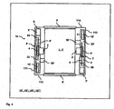
- each counterweight 2, 2 ' uses at least one counterweight guide rail 6, 6 ', 7, 7'.
- each counterweight 2, 2 ' uses a pair of counterweight guide rails 6, 6', 7, 7 '.
- the upper counterweight 2 has a first pair of counterweight guide rails 6, 6 ' mounted close to a first wall 111 and the lower counterweight 2' has a second pair of counterweight guide rails 7, 7 ' close to a first one Wall 112 is mounted.
- the cabins 1, 1 ' and the counterweights 2, 2' can be moved in 1: 2 suspension or in 1: 1 suspension.
- the conveyor 5, 5 ' via at least one guide roller 21,21', 20, 20 ' with the car 1, 1 or with the counterweight 2, 2' is connected.
- the conveyor is 5,5 ' connected with one end directly to the car 1, 1' and the counterweight 2, 2 ' .
- the cabins and the counterweights are 1: 2 umgeenfin.
- the cabins and the counterweights are 1: 2 umgeenfin.
- B spw. is a deflection roller 20, 20 ' above each counterweight 2, 2' arranged.
- the term "cabin guide rails or counterweight guide rails" is understood to mean a combination of cabin guide rails 3, 3 ' and / or counterweight guide rails 6, 6', 7, 7 ' .
- the conveying means 5, 5 ' extends from a first conveying means fixed point 50 on counterweight guide rails 6, 7' via the counterweight deflection roller 20, 20 ' to the traction sheave of the drive 4, 4' , from there via the cabin deflection rollers 21, 21 ' a second conveyor fixed point 50 ' on counterweight guide rails 6', 7.
- the conveyor fixing points 50, 50 ' are thus attached to guide rails close to two different first walls 111, 112 in the shaft 11 .
- the cabins and the counterweights are 1: 1 umgeenfin.
- the conveyor 5, 5 ' extends from a first conveyor fixed point 50 on the counterweight 2, 2' to the traction sheave of the drive 4, 4 ' and from there to a second conveyor fixed point 50' on the cabin 1,1 ' .
- the advantage of the 1: 2 suspension over the 1: 1 suspension is that comparatively less powerful and thus smaller and cheaper drives 4, 4 ' are used.
- 1: 2 suspension is compared to the 1: 1 suspension a twice as long conveyor 5, 5 ' needed, also several pulleys are required.
- other hangings such as 1: 4 and combinations of 1: 1 and 1: 2, etc. realize.
- the drives 4, 4 ' are mounted close to a first wall 111, 112 .
- the term "close to a first wall” is understood to mean an assembly of the drives 4, 4 ' on cab guide rails 3, 3' or on counterweight guide rails 6, 6 ', 7, 7' , which guide rails are close to a first one Wall 111, 112 are mounted, that is, which guide rails are basically free in the shaft, but, for example , are fixed to the first walls 111, 112 via brackets.
- the drives 4, 4 ' are arranged at substantially the same height in the shaft 11.
- the drives 4, 4 ' are arranged largely above the counterweights 2, 2' .
- electrical system 12, 12 ' for operating the elevator installation 10 is at least partially supported on the cabin guide rails 3, 3' or on the counterweight guide rails 6, 6 ', 7, 7 '.
- Such electrical system 12, 12 ' includes, for example, a converter for controlling the drives 4, 4' . or an electronics for the special operation of the elevator system 1 0, for example. In an emergency for evacuation or for revision work.
- the cabin guide rails 3, 3 ' and the counterweight guide rails 6, 6', 7, 7 ' thus form a self-supporting structure for supporting the cabins 1, 1' , the counterweights 2, 2 ' and for carrying elevator components such as Drives 4, 4 ' , and / or the electrical system 12, 12' and for fixing the conveyor fixing points 50, 50 ' .
- This self-supporting structure has minimal interfaces to the building, such as the fixing brackets of the guide rails.
- the self-supporting structure is largely symmetrical and mirrored with respect to a diagonal in the shaft cross-section. In the embodiments of the elevator installation 10 according to FIG Fig. 2 and 4 extends this diagonal of the corner of the walls 111 and 113 to the corner of the walls 112 and 114.
- the self-supporting structure in addition to the cabin guide rails 3, 3 ' and the counterweight guide rails 6, 6', 7, 7 ' also horizontal support 22, 22 ' on.
- a first horizontal beam 22 is disposed near a first wall 111 above the first car guide rail 3 and the first pair of counterweight guide rails 6, 6 ' , respectively.
- a second horizontal beam 22 ' is disposed near a first wall 112 above the second car guide rail 3 ' and the second pair of counterweight guide rails 7, 7 ' , respectively.
- the drives 4, 4 ' and / or the Elektik 12, 12 ' and / or the winning advicefixa 50, 50 ' on Horizontalträgem 22, 22' are arranged, which horizontal beams 22, 22 ' at the upper ends of the cabin guide rails 3, 3rd ' or the counterweight guide rails 6, 6', 7, 7 'are mounted.
- the person skilled in the art can realize many variants of the arrangement of elevator components and the design of the self-supporting structure.
- the person skilled in the art may also attach other elevator components, such as speed limiters, position markers, etc., which are not described in more detail here, to the self-supporting structure.
- the access to the cabins 1, 1 ' via floor doors 9, 9' which floor doors 9, 9 ' on second walls 113, 114 are arranged in the shaft 11 , which second walls 113, 114 of the first walls 111, 112 different are.
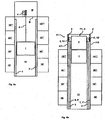
- Fig. 5 shows an embodiment of a modernized elevator installation 10, in which an existing machine room M is converted to at least one alternative room 8 .
- Fig. 5a shows the elevator installation before the modernization, where a machine room M is arranged above the shaft 11
- Fig. 5b the elevator installation 10 after the modernization, where an escape space 8 for at least one cabin 1, 1 'is provided in the shaft head 11' .
- the embodiment of a modernized elevator installation 10 according to Fig. 5b corresponds to that according to the Fig. 1 to 4 , so that reference is made to these parts of description.
- FIG. 5a and 5b strongly schematized. So the existing counterweights are not shown.
- This building space in the shaft head 11 ' is used as an alternative space 8 new.
- the upper cabin 1 ' is moved so far in this alternative space 8 , that not only the upper cabin 1' but also the lower cabin 1, the top floor 10 "operated" .
Description
Die Erfindung bezieht sich auf ein Verfahren zur Modernisierung einer Aufzugsanlage gemäss der Definition des Oberbegriffs des Patentanspruchs.The invention relates to a method for modernizing an elevator system according to the definition of the preamble of the claim.
Bei Neu-Installationen von Aufzugsanlagen besteht der Wunsch nach platzsparenden- und einfach zu installierenden Aufzugsanlagen. Dies führt dazu, dass die Aufzugsanlagen keine separaten Maschinenräume mehr benötigen, sondern in einfach konzipierte, standardisierte, quaderförmige Schächte passen. Somit reduzieren sich die Kosten bei Planung und Bau der Gebäude und erhöht sich der nutzbare Gebäuderaum.In new installations of elevator systems there is a desire for space-saving and easy to install elevator systems. This means that the elevator systems no longer require separate machine rooms, but fit into simply designed, standardized, cuboid shafts. This reduces the costs of planning and construction of the building and increases the usable building space.
Bei Modernisierungen von Aufzugsanlagen besteht der Wunsch nach Steigerung der Förderleistung der Aufzugsanlagen. Diese Leistungssteigerung soll jedoch mit geringen baulichen Veränderungen an den Gebäuden realisiert werden, um die Kosten der Modernisierung niedrig zu halten.In modernizations of elevator systems, there is a desire to increase the capacity of the elevator systems. However, this increase in performance should be realized with little structural changes to the buildings in order to keep the costs of modernization low.
Nachteilig an der Lehre gemäss
Auch
Aufgabe der Erfindung ist es, eine Aufzugsanlage bereitzustellen, die einfach und kostengünstig zu installieren ist, die eine hohe Förderleistung erbringt und mit der eine bestehende Aufzugsanlage einfach und kostengünstig zu modernisieren ist. Diese Aufzugsanlage soll mit bestehenden und bewährten Verfahren des Aufzugsbaus kompatibel sein.The object of the invention is to provide an elevator system that is easy and inexpensive to install, which provides a high capacity and with an existing elevator system is easy and inexpensive to modernize. This elevator system should be compatible with existing and proven elevator manufacturing processes.
Die Erfindung löst diese Aufgabe mit einem Verfahren zur Modernisierung einer Aufzugsanlage, das dadurch gekennzeichnet ist, dass in einem Schacht mindestens zwei, in vertikaler Verfahrrichtung übereinander angeordnete Kabinen montiert werden, mit mindestens einer Kabinen-Führungsschiene zum Führen der Kabinen, mit einem Antrieb pro Kabine, welche Antriebe nahe an verschiedenen ersten Wänden im Schacht angeordnet werden, mit Fördermitteln zum Verbinden der Antriebe und Kabinen, mit einem Gegengewicht pro Kabine, mit mindestens einer Gegengewichts-Führungsschiene pro Gegengewicht, welche Gegengewichte und die Gegengewichts-Führungsschienen nahe an den ersten Wänden im Schacht angeordnet werden, wobei die Antriebe auf weitgehend gleicher Höhe im Schacht angeordnet werden, und wobei mindestens ein Ausweichraum für mindestens eine Kabine vorgesehen wird, welcher Ausweichraum im Schachtkopf und/oder im Schachtboden angeordnet ist und ein bestehender Maschinenraum zu mindestens einem Ausweichraum für mindestens eine Kabine umgebaut wird.The invention achieves this object with a method for modernizing an elevator installation, which is characterized in that at least two cabins arranged one above the other in the vertical travel direction are mounted in a shaft, with at least one cabin guide rail for guiding the cars, with one drive per booth which drives are arranged close to various first walls in the shaft, with conveying means for connecting the drives and cabins, with a counterweight per cabin, with at least one counterweight guide rail per counterweight, which counterweights and the counterweight guide rails close to the first walls in the Shaft are arranged, wherein the drives are arranged at substantially the same height in the shaft, and wherein at least one escape space is provided for at least one cabin, which escape space is arranged in the shaft head and / or in the shaft bottom and an existing engine room to at least ei An alternative space for at least one cabin is rebuilt.
Die Antriebe sind also im Schacht, bspw. im Schachtkopf angeordnet. Auf diese Weise fällt der Maschinenraum weg, wodurch der Gebäuderaum optimal genutzt wird und gleichzeitig davon, durch den Einsatz von mindestens zwei Kabinen in ein und demselben Schacht eine signifikante Steigerung der Förderleistung erfolgt. Eine Montage von mehreren Antrieben im Schachtkopf ist wesentlich einfacher zu bewerkstelligen, als ausserhalb des Schachts im Maschinenraum. So können die Bestandteile der Antriebe durch den Schacht in den Schachtkopf transportiert werden.The drives are thus arranged in the shaft, for example in the shaft head. In this way, the engine room falls away, whereby the building space is used optimally and at the same time, by the use of at least two cabins in the same shaft, a significant increase in capacity occurs. An assembly of several drives in the shaft head is much easier to accomplish, than outside the shaft in the engine room. Thus, the components of the drives can be transported through the shaft in the shaft head.
Es ist ein Gegengewicht pro Kabine vorgesehen. Vorteilhafterweise sind die Antriebe weitgehend oberhalb der Gegengewichte im Schacht angeordnet. Die Antriebe sind auf weitgehend gleicher Höhe im Schacht angeordnet. Vorteilhafterweise ist jeder Antrieb einer Kabine oberhalb des Gegengewichts von dieser Kabine nahe an den ersten Wänden im Schacht angeordnet. Es ist mindestens eine Gegengewichts-Führungsschiene pro Gegengewicht vorgesehen. Vorteilhafterweise werden die Antriebe auf Enden der Führungsschienen für Kabine und Gegengewicht abgestützt. Vorteilhafterweise sind Fördermittelfixpunkte an den Führungsschienen für Kabine bzw. Gegengewicht befestigt. Vorteilhafterweise wird eine Elektrik für den Aufzug zumindestens teilweise auf den Führungsschienen für Kabine bzw. Gegengewicht abgestützt. Vorteilhaftweise werden die Antriebe und/oder die Elektrik direkt oder indirekt über Horizontalträger von den Führungsschienen für Kabine bzw. Gegengewicht getragen bzw. sind die Fördermittelfixpunkte direkt oder indirekt über Horizontalträger an den Führungsschienen für Kabine bzw. Gegengewicht befestigt.There is one counterweight per cabin. Advantageously, the drives are arranged largely above the counterweights in the shaft. The drives are arranged at largely the same height in the shaft. Advantageously, each drive of a car above the counterweight of that car is located close to the first walls in the manhole. At least one counterweight guide rail per counterweight is provided. Advantageously, the drives are supported on ends of the guide rails for cabin and counterweight. Advantageously, conveyor fixing points are fastened to the guide rails for the car or counterweight. Advantageously, an electrical system for the elevator is at least partially supported on the guide rails for the car or counterweight. Advantageously, the drives and / or the electrical system are supported directly or indirectly via horizontal beams of the guide rails for cabin or counterweight or the Fördermittelfixpunkte are attached directly or indirectly via horizontal support on the guide rails for cabin or counterweight.
Auf diese Weise wird anderweitig nicht nutzbarer Schachtraum oberhalb der Gegengewichte zur Montage der Antriebe und Elektrik in einem hohen Grad genutzt. Auch bilden die Führungsschienen für Kabine bzw. Gegengewicht bzw. die Horizontalträger eine selbsttragende Struktur zum Tragen der Antriebe, der Kabinen, des Gegengewichts und der Elektrik sowie zum Befestigen der Fördermittelfixpunkte. Diese Struktur ist weitgehend symmetrisch und bezüglich einer Diagonalen vom Schachtquerschnitt gespiegelt. Somit sind keine wesentlichen Schnittstelle zum Gebäude nötig, was die Neu-Installation und Montage der Aufzugsanlage vereinfacht.In this way, otherwise not usable shaft space above the counterweights for mounting the drives and electrical system is used to a high degree. The guide rails for cabin or counterweight or the horizontal support also form a self-supporting structure for supporting the drives, the cabins, the counterweight and the electrical system as well as for fixing the Fördermittelfixpunkte. This structure is largely symmetrical and mirrored with respect to a diagonal of the shaft cross-section. Thus, no essential interface to the building is necessary, which simplifies the re-installation and assembly of the elevator system.
Vorteilhafterweise erfolgt der Zugang zu den Kabinen über Stockwerkstüren, welche Stockwerkstüren an zweiten Wänden im Schacht angeordnet sind, welche zweiten Wände von den ersten Wänden verschieden sind. Vorteilhafterweise sind Führungsschienen, Gegengewichte und Antriebe nahe an zwei ersten Wänden angebracht, während die Stockwerkstüren an zwei zweiten Wänden angebracht sind.Advantageously, the access to the cabins is via floor doors, which floor doors are arranged on second walls in the shaft, which second walls are different from the first walls. Advantageously, guide rails, counterweights and drives are mounted close to two first walls, while the floor doors are mounted on two second walls.
Auf diese Weise wird nicht nur der Schachtraum, sondern auch die Wände des Schachts und somit der Zugang zur Aufzugsanlage optimal ausgenutzt. B spw. sind Führungsschienen, Gegengewichte und Antriebe nahe an zwei ersten Wänden im Schacht angebracht, während der Zugang zur Aufzugsanlage über Stockwerkstüren erfolgt, welche Stockwerkstüren an zwei zweiten Wänden angebracht sind.In this way, not only the shaft space, but also the walls of the shaft and thus the access to the elevator system is optimally utilized. B spw. Guide rails, counterweights and drives are mounted close to two first walls in the shaft, while access to the elevator system via floor doors, which floor doors are mounted on two second walls.
Erfindungsgemäss ist mindestens ein Ausweichraum für mindestens eine Kabine vorgesehen, welcher Ausweichraum im Schachtkopf und/oder im Schachtboden angeordnet ist. Erfindungsgemäss wird bei der Modernisierung ein bestehender Maschinenraum zu einem Ausweichraum für mindestens eine Kabine umgebaut.According to the invention, at least one escape space is provided for at least one cabin, which alternative space is arranged in the shaft head and / or in the shaft floor. According to the invention, during the modernization, an existing engine room is converted into an alternative space for at least one car.
Durch Vorsehen mindestens eines Ausweichraums oberhalb bzw. unterhalb der bedienten Stockwerke des Gebäudes kann eine erste Kabine in diesen Ausweichraum verfahren werden. Diese erste Kabine besetzt nun im Schachtbereich der bedienten Stockwerke keinen Platz mehr und eine weitere Kabine kann in diesen Platz verfahren werden. Somit kann nicht nur die erste Kabine sondern auch eine weitere Kabine das Stockwerk unterhalb bzw. oberhalb d es A usweichraums b edienen, w as i nbesondere im Stossbetrieb zu einer Steigerung der Förderleistung führt. Dadurch, dass bei einer Modernisierung ein bestehender Maschinenraum zu einem Ausweichraum umgebaut wird, erfolgt eine Neunutzung von Gebäuderaum zur wiederholten Steigerung der Förderleistung.By providing at least one escape space above or below the served floors of the building, a first cabin can be moved into this escape space. This first cabin occupies now no more space in the shaft area of the served floors and a further cabin can be moved into this place. Thus, not only the first cabin but also a further cabin can operate the floor below or above the outside space, in particular in the case of an impact operation leading to an increase in the delivery capacity. The fact that an existing engine room is converted into an alternative space in a modernization, reuse of building space to repeatedly increase the capacity.
Nachstehend wird die Erfindung anhand von beispielhaften Ausführungsformen im Detail erläutert. Hierbei zeigt:
- Fig. 1
- eine schematische Seitenansicht eines Teils einer ersten Ausführungsform einer Aufzugsanlage mit zwei 2:1 umgehängten Kabinen in einem Schacht,
- Fig. 2
- eine schematische Draufssicht eines Teils der ersten Ausführungsform einer Aufzugsanlage gemäss
Fig. 1 , - Fig. 3
- eine schematische Seitenansichten eines Teils einer zweiten Ausführungsform einer Aufzugsanlage mit zwei 1:1 umgehängten Kabinen in einem Schacht, und
- Fig. 4
- eine schematische Draufssicht eines Teils der zweiten Ausführungsform einer Aufzugsanlage gemäss
Fig. 3 , - Fig. 5
- zwei schematische Seitenansichten eines Teils einer Ausführungsform einer modernisierten Aufzugsanlage, bei der ein bestehender Maschinenraum zu einem Ausweichraum umgebaut wird.
- Fig. 1
- 1 is a schematic side view of part of a first embodiment of an elevator installation with two 2: 1 cabins suspended in a shaft;
- Fig. 2
- a schematic plan view of a portion of the first embodiment of an elevator system according to
Fig. 1 . - Fig. 3
- a schematic side views of a portion of a second embodiment of an elevator system with two 1: 1 umhängengten cabins in a shaft, and
- Fig. 4
- a schematic plan view of a portion of the second embodiment of an elevator system according to
Fig. 3 . - Fig. 5
- two schematic side views of a part of an embodiment of a modernized elevator installation, in which an existing engine room is converted into an alternative space.
Die
Die Aufzugsanlage 10 weist mindestens zwei Kabinen 1, 1' auf, welche Kabinen in vertikaler Verfahrrichtung übereinander im Schacht 11 verfahren werden. Unter dem Begriff "übereinander verfahrbar" wird ein nicht Überfahren der jeweils anderen Kabine verstanden, d.h. eine untere Kabine 1 bleibt immer unterhalb einer oberen Kabine 1'. Bei den Kabinen 1, 1' handelt es sich um übliche und bewährte Aufzugskabinen, die über Führungsschuhe an mindestens einer Kabinen-Führungsschiene 3, 3' verfahren werden. Vorteilhafterweise verwenden beide Kabinen 1, 1' zwei Kabinen-Führungsschienen 3, 3' nahe an verschiedenen ersten Wänden 111, 112. Es ist eine erste Kabinen-Führungsschiene 3 nahe an einer ersten Wand 111 angeordnet und eine zweite Kabinen-Führungsschiene 3' ist nahe an einer weiteren ersten Wand 112 angeordnet. Bei Kenntnis der vorliegenden Erfindung lassen sich auf diese Weise natürlich auch mehr als zwei Kabinen 1, 1' entlang von Kabinen-Führungsschienen 3, 3' in einem Schacht 11 verfahren. Auch kann der Fachmann anstatt eines Paares von Kabinen-Führungsschienen eine einzige Kabinen-Führungsschiene vorsehen.The
Die Aufzugsanlage 10 weist pro Kabine 1, 1' einen Antrieb 4, 4' auf. Ein erster Antrieb 4 treibt die obere Kabine 1' an, ein zweiter Antrieb 4' treibt die untere Kabine 1 an. Beim Antrieb 4, 4' handelt es sich bspw. um einen Treibscheibenantrieb. Bei Kenntnis der vorliegenden Erfindung lassen sich alle bekannten und bewährten Antriebe verwenden. Bspw. lassen sich getriebelose Antriebe oder solche mit Getriebe verwenden. Auch lassen sich Antriebe mit Permanentmagneten, mit Synchronmotor oder Asynchronmotor verwenden.The
Die Aufzugsanlage 10 weist pro Kabine 1, 1' ein Gegengewicht 2, 2' auf. Ein Treibscheibenantrieb verbindet über mindestens ein Fördermittel 5, 5' eine Kabine 1, 1' mit einem Gegengewicht 2, 2' und treibt diese an. Ein erstes Fördermittel 5 verbindet die untere Kabine 1 mit einem oberen Gegengewicht 2 und ein zweites Fördermittel 5' verbindet die obere Kabine 1' mit einem unteren Gegengewicht 2'. Vorteilhafterweise werden die Gegengewichte 2, 2' neben den Kabinen 1, 1' verfahren. Bspw. werden die Kabinen 1,1' in der Schachtmitte verfahren und die Gegengewichte 2, 2' werden am Schachtrand nahe an ersten Wänden 111, 112 verfahren. Das Fördermittel 5, 5' kann eine beliebige Form haben, auch kann es aus beliebigen Materialien sein. Bspw. ist das Fördermittel 5, 5' ein Rundseil, Doppelseil oder ein Riemen. Bspw. ist das Fördermittel 5, 5' zumindestens teilweise aus Stahl bzw. Aramidfasern.The
In den Ausführungsformen einer Aufzugsanlage 10 gemäss
Die Kabinen 1, 1' bzw. die Gegengewichte 2, 2' lassen sich in 1:2 Umhängung bzw. in 1:1 Umhängung verfahren. Bei 1:2-Umhängung ist das Fördermittel 5, 5' über mindestens eine Umlenkrolle 21,21', 20, 20' mit der Kabine 1, 1 bzw. mit dem Gegengewicht 2, 2' verbunden. Bei 1:1-Umhängung ist das Fördermittel 5,5' mit einem Ende direkt an der Kabine 1, 1' bzw. am Gegengewicht 2, 2' angebunden.The
In der Ausführungsform einer Aufzugsanlage 10 gemäss
In der Ausführungsform einer Aufzugsanlage 10 gemäss
Die Antriebe 4, 4' sind nahe an einer ersten Wand 111, 112 montiert. Unter dem Begriff "nahe an einer ersten Wand" wird eine Montage der Antriebe 4, 4' auf Kabinen-Führungsschienen 3, 3' bzw. an Gegengewichts-Führungsschienen 6, 6', 7, 7' verstanden, welche Führungschienen nahe an einer ersten Wand 111, 112 montiert sind, d.h. welche Führungsschienen prinzipiell frei im Schacht stehen, aber bspw. über Klammern an ersten Wänden 111, 112 fixiert sind. Mit dem Begriff "prinzipiell freistehend" wird eine Einleitung weitgehend aller beim Betrieb der Aufzugsanlage 10' auftretenden Kräfte über die Kabinen-Führungsschienen 3, 3' bzw. die Gegengewichts-Führungsschienen 6, 6', 7, 7' in den Schachtboden 11" verstanden. Mit dem Begriff "weitgehend alle beim Betrieb der Aufzugsanlage 10' auftretenden Kräfte" werden zum einen die Kräfte verstanden, die im Normalbetrieb auftreten, aber es werden auch solche Kräfte verstanden, die im Notfall, bspw. beim Einrücken der Fangvorrichtung, bei Pufferfahrten von Kabine oder Gegengewichten, usw. auftreten.The
Vorteilhafterweise sind die Antriebe 4, 4' auf den Kabinen-Führungsschienen 3, 3' bzw. an den Gegengewichts-Führungsschienen 6, 6', 7, 7' abgestützt. Vorteilhafterweise sind die Antriebe 4, 4' auf weitgehend gleicher Höhe im Schacht 11 angeordnet. Die Antriebe 4, 4' sind weitgehend oberhalb der Gegengewichte 2, 2' angeordnet. Vorteilhafterweise ist Elektrik 12, 12' zum Betreiben der Aufzugsanlage 10 zumindestens teilweise auf den Kabinen-Führungsschienen 3, 3' bzw. an den Gegengewichts-Führungsschienen 6, 6', 7, 7' abgestützt. Solche Elektrik 12, 12' umfasst bspw. einen Umrichter für die Ansteuerung der Antriebe 4, 4'. bzw. eine Elektronik für den Sonderbetrieb der Aufzugsanlage 10, bspw. im Notfall zum Evakuieren oder bei Revisionsarbeiten.Advantageously, the
Die Kabinen-Führungsschienen 3, 3' bzw. die Gegengewichts-Führungsschienen 6, 6', 7, 7' bilden also eine selbsttragende Struktur zum Tragen der Kabinen 1, 1', der Gegengewichte 2, 2' sowie zum Tragen von Aufzugskomponenten wie die Antriebe 4, 4', und/oder der Elektrik 12, 12' sowie zum Befestigen der Fördermittelfixpunkte 50, 50'. Diese selbsttragende Struktur weist zum Gebäude hin minimale Schnittstellen wie die Fixierungsklammern der Führungsschienen auf. Die selbsttragende Struktur ist weitgehend symmetrisch aufgebaut und bezüglich einer Diagonalen im Schachtquerschnitt gespiegelt. In der Ausführungsformen der Aufzugsanlage 10 gemäss
Vorteilhafterweise erfolgt der Zugang zu den Kabinen 1, 1' über Stockwerkstüren 9, 9', welche Stockwerkstüren 9, 9' an zweiten Wänden 113, 114 im Schacht 11 angeordnet sind, welche zweiten Wände 113, 114 von den ersten Wänden 111, 112 verschieden sind. In den Ausführungsformen einer Aufzugsanlage 10 gemäss den
Aus Gründen der Übersichtlichkeit sind die
Claims (1)
- Method of modernising a lift installation, characterised in that at least two cages (1, 1') arranged one above the other in vertical travel direction are mounted in a shaft (11), with at least one cage guide rail (3, 3') for guiding the cages (1, 1'), a drive (4, 4') for each cage (1, 1'), which drives (4, 4') are arranged in the shaft (11) near different first walls (111, 112), conveying means (5, 5') for connecting the drives (4, 4') and cages (1, 1'), a counterweight (2, 2') for each cage (1, 1'), and at least one counterweight guide rail (6, 6', 7, 7') for each counterweight (2, 2'), which counterweights (2, 2') and the counterweight guide rails (6, 6', 7, 7') are arranged near the first walls (111, 112) in the shaft (11), wherein the drives (4, 4') are arranged in the shaft (11) at substantially the same height and wherein at least one diversion space (8) for at least one cage (1, 1') is provided, which diversion space (8) is arranged in the shaft head (11') and/or in the shaft base (11") and an existing engine room is converted to at least one diversion space (8) for at least one cage (1, 1').
Priority Applications (1)
| Application Number | Priority Date | Filing Date | Title |
|---|---|---|---|
| EP04013309.2A EP1489033B2 (en) | 2003-06-18 | 2004-06-05 | Elevator with two cars arranged one above the other in the same hoistway |
Applications Claiming Priority (3)
| Application Number | Priority Date | Filing Date | Title |
|---|---|---|---|
| EP03405439 | 2003-06-18 | ||
| EP03405439 | 2003-06-18 | ||
| EP04013309.2A EP1489033B2 (en) | 2003-06-18 | 2004-06-05 | Elevator with two cars arranged one above the other in the same hoistway |
Publications (3)
| Publication Number | Publication Date |
|---|---|
| EP1489033A1 EP1489033A1 (en) | 2004-12-22 |
| EP1489033B1 EP1489033B1 (en) | 2008-11-12 |
| EP1489033B2 true EP1489033B2 (en) | 2015-05-27 |
Family
ID=33420609
Family Applications (1)
| Application Number | Title | Priority Date | Filing Date |
|---|---|---|---|
| EP04013309.2A Not-in-force EP1489033B2 (en) | 2003-06-18 | 2004-06-05 | Elevator with two cars arranged one above the other in the same hoistway |
Country Status (1)
| Country | Link |
|---|---|
| EP (1) | EP1489033B2 (en) |
Families Citing this family (14)
| Publication number | Priority date | Publication date | Assignee | Title |
|---|---|---|---|---|
| EP1882670B1 (en) * | 2006-07-25 | 2017-10-25 | Inventio AG | Method for modernising a lift facility |
| IL184194A (en) | 2006-07-25 | 2012-02-29 | Inventio Ag | Method of modernizing a lift installation |
| EP1886957A1 (en) | 2006-08-11 | 2008-02-13 | Inventio Ag | Lift belt for a lift system and method for manufacturing such a lift belt |
| NZ562338A (en) | 2006-10-31 | 2009-07-31 | Inventio Ag | Lift with two lift cages disposed one above the other in a lift shaft |
| EP1935829A1 (en) | 2006-12-21 | 2008-06-25 | Inventio Ag | Elevator comprising two elevator cars in a shaft |
| US7882934B2 (en) | 2006-12-22 | 2011-02-08 | Inventio Ag | Elevator installation in a building with at least one transfer floor |
| EP1935828B1 (en) | 2006-12-22 | 2014-04-16 | Inventio AG | Lift system for a building with at least two floors |
| US7913818B2 (en) | 2006-12-22 | 2011-03-29 | Inventio Ag | Elevator installation in a building with at least one transfer floor |
| EP1935825A1 (en) | 2006-12-22 | 2008-06-25 | Inventio Ag | Lift system for a building with at least two floors |
| DE202008001786U1 (en) | 2007-03-12 | 2008-12-24 | Inventio Ag | Elevator installation, suspension element for an elevator installation and device for producing a suspension element |
| WO2010072656A1 (en) | 2008-12-26 | 2010-07-01 | Inventio Ag | A plurality of elevator cars in an elevator shaft with improved shaft utilization |
| WO2010072657A1 (en) | 2008-12-26 | 2010-07-01 | Inventio Ag | Counterweight in an elevator installation |
| DE102014220629A1 (en) * | 2014-10-10 | 2016-04-14 | Thyssenkrupp Ag | Method for operating an elevator installation |
| DE102022119470A1 (en) | 2022-08-03 | 2024-02-08 | Tk Elevator Innovation And Operations Gmbh | Elevator system with two elevator cars arranged one above the other in an elevator shaft |
Citations (1)
| Publication number | Priority date | Publication date | Assignee | Title |
|---|---|---|---|---|
| JP2001240318A (en) † | 2000-02-28 | 2001-09-04 | Toshiba Corp | Elevator system |
Family Cites Families (2)
| Publication number | Priority date | Publication date | Assignee | Title |
|---|---|---|---|---|
| JP4786121B2 (en) * | 2000-10-10 | 2011-10-05 | 三菱電機株式会社 | Elevator equipment |
| JPWO2002072460A1 (en) * | 2001-03-14 | 2004-07-02 | 株式会社日立製作所 | Elevator renewal method |
-
2004
- 2004-06-05 EP EP04013309.2A patent/EP1489033B2/en not_active Not-in-force
Patent Citations (1)
| Publication number | Priority date | Publication date | Assignee | Title |
|---|---|---|---|---|
| JP2001240318A (en) † | 2000-02-28 | 2001-09-04 | Toshiba Corp | Elevator system |
Also Published As
| Publication number | Publication date |
|---|---|
| EP1489033B1 (en) | 2008-11-12 |
| EP1489033A1 (en) | 2004-12-22 |
Similar Documents
| Publication | Publication Date | Title |
|---|---|---|
| DE69907129T3 (en) | Traction elevator | |
| DE69418496T3 (en) | Traction sheave elevator | |
| EP1326797B1 (en) | Elevator with drive unit mounted in a superior lateral section of the elevator hoistway | |
| EP1056678B1 (en) | Preassembled elevator shaft | |
| EP1489033B2 (en) | Elevator with two cars arranged one above the other in the same hoistway | |
| DE3802386C2 (en) | Elevator system | |
| EP1935829A1 (en) | Elevator comprising two elevator cars in a shaft | |
| DE102006044669A1 (en) | Machine roomless propulsion lift | |
| DE19718626C1 (en) | Rope driven elevator | |
| EP1526103A1 (en) | Multiple deck elevator system for group elevators | |
| EP0913353B1 (en) | Modular construction of elevator installation | |
| DE60217935T3 (en) | SCREEN ARRANGEMENT FOR AN ELEVATOR SYSTEM | |
| EP0534122B1 (en) | Hydraulic rope lift | |
| DE10319731B4 (en) | elevator | |
| AT410784B (en) | LIFT | |
| DE10154171A1 (en) | Hydraulic lift (elevator) modernizing process involves dismantling drive and cable, fitting counterweight with pulley and pulley drive unit, diverting pulley and fixing devices | |
| DE19963286B4 (en) | elevator | |
| EP2468674A1 (en) | Lift facility with double decker | |
| EP2516309B1 (en) | Lift with a counterweight | |
| DE102021004070A1 (en) | Machine room-less elevator system | |
| EP3235770B1 (en) | Method for retrofitting an elevator and corresponding elevator | |
| WO2016020394A1 (en) | Elevator system | |
| DE19752227A1 (en) | Preassembled elevator shaft | |
| DE19963297B4 (en) | elevator | |
| DE20104416U1 (en) | Rope-driven elevator for installation in the stairwell of a stairwell |
Legal Events
| Date | Code | Title | Description |
|---|---|---|---|
| PUAI | Public reference made under article 153(3) epc to a published international application that has entered the european phase |
Free format text: ORIGINAL CODE: 0009012 |
|
| AK | Designated contracting states |
Kind code of ref document: A1 Designated state(s): AT BE BG CH CY CZ DE DK EE ES FI FR GB GR HU IE IT LI LU MC NL PL PT RO SE SI SK TR |
|
| AX | Request for extension of the european patent |
Extension state: AL HR LT LV MK |
|
| REG | Reference to a national code |
Ref country code: HK Ref legal event code: DE Ref document number: 1071558 Country of ref document: HK |
|
| 17P | Request for examination filed |
Effective date: 20050607 |
|
| AKX | Designation fees paid |
Designated state(s): AT CH DE FR GB LI |
|
| 17Q | First examination report despatched |
Effective date: 20060904 |
|
| GRAP | Despatch of communication of intention to grant a patent |
Free format text: ORIGINAL CODE: EPIDOSNIGR1 |
|
| GRAS | Grant fee paid |
Free format text: ORIGINAL CODE: EPIDOSNIGR3 |
|
| GRAA | (expected) grant |
Free format text: ORIGINAL CODE: 0009210 |
|
| AK | Designated contracting states |
Kind code of ref document: B1 Designated state(s): AT CH DE FR GB LI |
|
| REG | Reference to a national code |
Ref country code: GB Ref legal event code: FG4D Free format text: NOT ENGLISH |
|
| REG | Reference to a national code |
Ref country code: CH Ref legal event code: EP |
|
| REF | Corresponds to: |
Ref document number: 502004008438 Country of ref document: DE Date of ref document: 20081224 Kind code of ref document: P |
|
| REG | Reference to a national code |
Ref country code: HK Ref legal event code: GR Ref document number: 1071558 Country of ref document: HK |
|
| PLBI | Opposition filed |
Free format text: ORIGINAL CODE: 0009260 |
|
| PLAX | Notice of opposition and request to file observation + time limit sent |
Free format text: ORIGINAL CODE: EPIDOSNOBS2 |
|
| 26 | Opposition filed |
Opponent name: OTIS ELEVATOR COMPANY Effective date: 20090812 |
|
| PLAF | Information modified related to communication of a notice of opposition and request to file observations + time limit |
Free format text: ORIGINAL CODE: EPIDOSCOBS2 |
|
| PLBB | Reply of patent proprietor to notice(s) of opposition received |
Free format text: ORIGINAL CODE: EPIDOSNOBS3 |
|
| APAH | Appeal reference modified |
Free format text: ORIGINAL CODE: EPIDOSCREFNO |
|
| APBM | Appeal reference recorded |
Free format text: ORIGINAL CODE: EPIDOSNREFNO |
|
| APBP | Date of receipt of notice of appeal recorded |
Free format text: ORIGINAL CODE: EPIDOSNNOA2O |
|
| APBQ | Date of receipt of statement of grounds of appeal recorded |
Free format text: ORIGINAL CODE: EPIDOSNNOA3O |
|
| APBU | Appeal procedure closed |
Free format text: ORIGINAL CODE: EPIDOSNNOA9O |
|
| PUAH | Patent maintained in amended form |
Free format text: ORIGINAL CODE: 0009272 |
|
| STAA | Information on the status of an ep patent application or granted ep patent |
Free format text: STATUS: PATENT MAINTAINED AS AMENDED |
|
| 27A | Patent maintained in amended form |
Effective date: 20150527 |
|
| AK | Designated contracting states |
Kind code of ref document: B2 Designated state(s): AT CH DE FR GB LI |
|
| REG | Reference to a national code |
Ref country code: DE Ref legal event code: R102 Ref document number: 502004008438 Country of ref document: DE |
|
| REG | Reference to a national code |
Ref country code: CH Ref legal event code: AELC |
|
| REG | Reference to a national code |
Ref country code: HK Ref legal event code: AM43 Ref document number: 1071558 Country of ref document: HK |
|
| REG | Reference to a national code |
Ref country code: FR Ref legal event code: PLFP Year of fee payment: 13 |
|
| REG | Reference to a national code |
Ref country code: FR Ref legal event code: PLFP Year of fee payment: 14 |
|
| PGFP | Annual fee paid to national office [announced via postgrant information from national office to epo] |
Ref country code: SK Payment date: 20170613 Year of fee payment: 14 |
|
| PGFP | Annual fee paid to national office [announced via postgrant information from national office to epo] |
Ref country code: AT Payment date: 20170622 Year of fee payment: 14 |
|
| REG | Reference to a national code |
Ref country code: FR Ref legal event code: PLFP Year of fee payment: 15 |
|
| REG | Reference to a national code |
Ref country code: CH Ref legal event code: PL |
|
| REG | Reference to a national code |
Ref country code: AT Ref legal event code: MM01 Ref document number: 414034 Country of ref document: AT Kind code of ref document: T Effective date: 20180605 |
|
| PG25 | Lapsed in a contracting state [announced via postgrant information from national office to epo] |
Ref country code: CH Free format text: LAPSE BECAUSE OF NON-PAYMENT OF DUE FEES Effective date: 20180630 Ref country code: LI Free format text: LAPSE BECAUSE OF NON-PAYMENT OF DUE FEES Effective date: 20180630 Ref country code: AT Free format text: LAPSE BECAUSE OF NON-PAYMENT OF DUE FEES Effective date: 20180605 |
|
| PGFP | Annual fee paid to national office [announced via postgrant information from national office to epo] |
Ref country code: FR Payment date: 20210625 Year of fee payment: 18 |
|
| PGFP | Annual fee paid to national office [announced via postgrant information from national office to epo] |
Ref country code: GB Payment date: 20210625 Year of fee payment: 18 |
|
| PGFP | Annual fee paid to national office [announced via postgrant information from national office to epo] |
Ref country code: DE Payment date: 20210827 Year of fee payment: 18 |
|
| REG | Reference to a national code |
Ref country code: DE Ref legal event code: R119 Ref document number: 502004008438 Country of ref document: DE |
|
| GBPC | Gb: european patent ceased through non-payment of renewal fee |
Effective date: 20220605 |
|
| PG25 | Lapsed in a contracting state [announced via postgrant information from national office to epo] |
Ref country code: FR Free format text: LAPSE BECAUSE OF NON-PAYMENT OF DUE FEES Effective date: 20220630 |
|
| PG25 | Lapsed in a contracting state [announced via postgrant information from national office to epo] |
Ref country code: GB Free format text: LAPSE BECAUSE OF NON-PAYMENT OF DUE FEES Effective date: 20220605 Ref country code: DE Free format text: LAPSE BECAUSE OF NON-PAYMENT OF DUE FEES Effective date: 20230103 |