EP1488918A1 - Decorative sheet, shaped product, automobile, and method for producing shaped product - Google Patents
Decorative sheet, shaped product, automobile, and method for producing shaped product Download PDFInfo
- Publication number
- EP1488918A1 EP1488918A1 EP03782912A EP03782912A EP1488918A1 EP 1488918 A1 EP1488918 A1 EP 1488918A1 EP 03782912 A EP03782912 A EP 03782912A EP 03782912 A EP03782912 A EP 03782912A EP 1488918 A1 EP1488918 A1 EP 1488918A1
- Authority
- EP
- European Patent Office
- Prior art keywords
- molded article
- decorative sheet
- production method
- spread suppressing
- suppressing member
- Prior art date
- Legal status (The legal status is an assumption and is not a legal conclusion. Google has not performed a legal analysis and makes no representation as to the accuracy of the status listed.)
- Granted
Links
Images


Classifications
-
- B—PERFORMING OPERATIONS; TRANSPORTING
- B44—DECORATIVE ARTS
- B44C—PRODUCING DECORATIVE EFFECTS; MOSAICS; TARSIA WORK; PAPERHANGING
- B44C1/00—Processes, not specifically provided for elsewhere, for producing decorative surface effects
- B44C1/10—Applying flat materials, e.g. leaflets, pieces of fabrics
- B44C1/105—Applying flat materials, e.g. leaflets, pieces of fabrics comprising an adhesive layer
-
- B—PERFORMING OPERATIONS; TRANSPORTING
- B60—VEHICLES IN GENERAL
- B60R—VEHICLES, VEHICLE FITTINGS, OR VEHICLE PARTS, NOT OTHERWISE PROVIDED FOR
- B60R13/00—Elements for body-finishing, identifying, or decorating; Arrangements or adaptations for advertising purposes
- B60R13/02—Internal Trim mouldings ; Internal Ledges; Wall liners for passenger compartments; Roof liners
-
- B—PERFORMING OPERATIONS; TRANSPORTING
- B60—VEHICLES IN GENERAL
- B60R—VEHICLES, VEHICLE FITTINGS, OR VEHICLE PARTS, NOT OTHERWISE PROVIDED FOR
- B60R13/00—Elements for body-finishing, identifying, or decorating; Arrangements or adaptations for advertising purposes
- B60R13/04—External Ornamental or guard strips; Ornamental inscriptive devices thereon
-
- Y—GENERAL TAGGING OF NEW TECHNOLOGICAL DEVELOPMENTS; GENERAL TAGGING OF CROSS-SECTIONAL TECHNOLOGIES SPANNING OVER SEVERAL SECTIONS OF THE IPC; TECHNICAL SUBJECTS COVERED BY FORMER USPC CROSS-REFERENCE ART COLLECTIONS [XRACs] AND DIGESTS
- Y10—TECHNICAL SUBJECTS COVERED BY FORMER USPC
- Y10T—TECHNICAL SUBJECTS COVERED BY FORMER US CLASSIFICATION
- Y10T156/00—Adhesive bonding and miscellaneous chemical manufacture
- Y10T156/10—Methods of surface bonding and/or assembly therefor
-
- Y—GENERAL TAGGING OF NEW TECHNOLOGICAL DEVELOPMENTS; GENERAL TAGGING OF CROSS-SECTIONAL TECHNOLOGIES SPANNING OVER SEVERAL SECTIONS OF THE IPC; TECHNICAL SUBJECTS COVERED BY FORMER USPC CROSS-REFERENCE ART COLLECTIONS [XRACs] AND DIGESTS
- Y10—TECHNICAL SUBJECTS COVERED BY FORMER USPC
- Y10T—TECHNICAL SUBJECTS COVERED BY FORMER US CLASSIFICATION
- Y10T428/00—Stock material or miscellaneous articles
- Y10T428/24—Structurally defined web or sheet [e.g., overall dimension, etc.]
- Y10T428/24802—Discontinuous or differential coating, impregnation or bond [e.g., artwork, printing, retouched photograph, etc.]
- Y10T428/24851—Intermediate layer is discontinuous or differential
- Y10T428/24868—Translucent outer layer
- Y10T428/24876—Intermediate layer contains particulate material [e.g., pigment, etc.]
-
- Y—GENERAL TAGGING OF NEW TECHNOLOGICAL DEVELOPMENTS; GENERAL TAGGING OF CROSS-SECTIONAL TECHNOLOGIES SPANNING OVER SEVERAL SECTIONS OF THE IPC; TECHNICAL SUBJECTS COVERED BY FORMER USPC CROSS-REFERENCE ART COLLECTIONS [XRACs] AND DIGESTS
- Y10—TECHNICAL SUBJECTS COVERED BY FORMER USPC
- Y10T—TECHNICAL SUBJECTS COVERED BY FORMER US CLASSIFICATION
- Y10T428/00—Stock material or miscellaneous articles
- Y10T428/24—Structurally defined web or sheet [e.g., overall dimension, etc.]
- Y10T428/24802—Discontinuous or differential coating, impregnation or bond [e.g., artwork, printing, retouched photograph, etc.]
- Y10T428/24917—Discontinuous or differential coating, impregnation or bond [e.g., artwork, printing, retouched photograph, etc.] including metal layer
Definitions
- the present invention relates to a molded article which is decorated, and a production method thereof.
- the present invention also relates to a decorative sheet used for decorating such a molded article, and a motor vehicle provided with such a molded article.
- the decorative sheet disclosed in the above-identified publication includes a base member and an ink layer formed on a surface of the base member by printing.
- the decorative sheet is attached to a molded article with an adhesive.
- the molded article can be easily recycled as compared with the case of paint application using a coating material.
- such a decorative sheet can create beautiful appearance which is different from the paint application, so that a decorative quality can be improved.
- a conventional decorative sheet is, however, suitable for the decoration of a molded article having a flat surface, but is not suitable for the decoration of a molded article having an uneven surface.
- the decorative sheet is spread so as to follow the unevenness. Therefore, if a pattern of a character, a graphic symbol, a picture, and the like is represented in part of the decorative sheet, the pattern is deformed, and the decorative appearance is uglified.
- the present invention has been conducted in view of the above-described problems, and the object of the present invention is to provide a decorative sheet preferably used for the decoration of a molded article having an uneven surface, a molded article to which the decorative sheet is attached, a production method thereof, and a motor vehicle provided with such a molded article.
- the decorative sheet of the present invention includes: a base member, formed from a resin material, having a first and a second principal surfaces opposite to each other; a decoration layer, provided on the first principal surface of the base member, having a pattern area representing a predetermined pattern; and a spread suppressing member, provided in a position corresponding to the pattern area on the side of the first principal surface or on the side of the second principal surface of the base member, for suppressing the spreading of the pattern area of the decoration layer, thereby attaining the above-mentioned object.
- the resin material is a thermoplastic resin material.
- the spread suppressing member has a higher coefficient of thermal conductivity than a coefficient of thermal conductivity of the base member.
- the spread suppressing member is formed from a material including metal or a metal compound.
- the spread suppressing member is formed of metal.
- a coefficient of thermal conductivity of the spread suppressing member is 10 W/m ⁇ K or more.
- a thickness of the spread suppressing member is 5 ⁇ m or more and 100 ⁇ m or less.
- the spread suppressing member includes a first portion which overlaps the pattern area.
- the spread suppressing member includes a second portion positioned in an outer circumference of the first portion.
- a width of the second portion of the spread suppressing member is 1 mm or more and 10 mm or less.
- a width of the second portion of the spread suppressing member is 2 mm or more and 8 mm or less.
- the molded article according to the present invention includes a molded article body and the decorative sheet with the above-described structure which is joined to a surface of the molded article body, thereby attaining the above-mentioned object.
- the molded article according to the present invention includes: a molded article body; and a sheet joined to a surface of the molded article body, wherein the sheet includes a base member and a decoration layer provided on a face of the base member on the side of the molded article body, the decoration layer has a pattern area representing a predetermined pattern, and a portion of the sheet corresponding to the pattern area has a thickness which is 1.1 times or more and 1.8 times or less as large as a thickness of the other portion of the sheet, thereby attaining the above-mentioned object.
- the portion of the sheet corresponding to the pattern area has a thickness which is 1.2 times or more and 1.6 times or less as large as the thickness of the other portion of the sheet.
- the motor vehicle according to the present invention includes the molded article having the above-described structure, thereby attaining the above-mentioned object.
- the production method of a molded article according to the present invention includes the steps of: preparing a decorative sheet including: a base member, formed from a resin material, having a first and a second principal surfaces opposite to each other; a decoration layer, provided on the first principal surface of the base member, having a pattern area representing a predetermined pattern; and a spread suppressing member, provided in a position corresponding to the pattern area on the side of the first principal surface or on the side of the second principal surface of the base member, for suppressing the spreading of the pattern area of the decoration layer; preparing a molded article body; and joining the decorative sheet to a surface of the molded article body, thereby attaining the above-mentioned object.
- the production method of a molded article according to the present invention includes, before the step of joining the decorative sheet to the surface of the molded article body, the step of heating the decorative sheet.
- the resin material is a thermoplastic resin material.
- the spread suppressing member has a higher coefficient of thermal conductivity than a coefficient of thermal conductivity of the base member.
- the spread suppressing member is formed form a material including metal or a metal compound.
- the spread suppressing member is formed of metal.
- the coefficient of thermal conductivity of the spread suppressing member is 10 W/m ⁇ K or more.
- a thickness of the spread suppressing member is 5 ⁇ m or more and 100 ⁇ m or less.
- the spread suppressing member has a first portion which overlaps the pattern area.
- the spread suppressing member includes a second portion positioned in an outer circumference of the first portion.
- a width of the second portion of the spread suppressing member is 1 mm or more and 10 mm or less.
- a width of the second portion of the spread suppressing member is 2 mm or more and 8 mm or less.
- the step of joining the decorative sheet to the surface of the molded article body includes the step of moving the heated decorative sheet closer to the molded article body, and the step of reducing a pressure of a first space formed between the decorative sheet coming closer to the molded article body and the molded article body as compared with a pressure of a second space expanded oppositely to the first space with respect to the decorative sheet.
- the step of moving the decorative sheet closer to the molded article body is performed in such a manner that the spread suppressing member faces the second space.
- in the production method of a molded article according to the present invention includes, after the step of moving the decorative sheet closer to the molded body, the step of cooling the spread suppressing member by introducing a gas into the second space.
- the production method of a molded article according to the present invention includes, after the step of joining the decorative sheet to the surface of the molded body, the step of removing the spread suppressing member.
- the spread suppressing member is provided on the side of the second principal surface of the base member.
- the decoration layer is positioned between the base member and the molded article body.
- the molded article body includes a first member and a second member disposed on a surface of the first member, and in the step of joining the decorative sheet to the surface of the molded article body, the decorative sheet is joined to the surface of the molded article body so as to cover both of the first member and the second member, thereby joining the first member and the second member.
- the production method of a molded article according to the present invention includes the steps of: preparing a decorative sheet including a base member, formed from a resin material, having a first and a second principal surfaces opposite to each other, and a decoration layer, provided on the first principal surface of the base member, having a pattern area representing a predetermined pattern; preparing a molded article body; heating the decorative sheet; and joining the decorative sheet which is heated to a surface of the molded article body in a condition where a temperature of a portion of the decorative sheet corresponding to the pattern area is lower than a temperature of the other portion of the decorative sheet, thereby attaining the above-mentioned object.
- the step of joining the decorative sheet to the surface of the molded article body includes the step of cooling the decorative sheet in such a manner that the temperature of the portion corresponding to the pattern area is rapidly lowered as compared with the temperature of the other portion.
- the decorative sheet further includes a member, provided in a position corresponding to the pattern area on the side of the first principal surface or on the side of the second principal surface of the base member, having a higher coefficient of thermal conductivity than a coefficient of thermal conductivity of the base member.
- the member is formed from a material including metal.
- the member is formed of metal.
- a coefficient of thermal conductivity of the member is 10 W/m ⁇ K or more.
- the motor vehicle according to the present invention includes the molded article produced by the above-described production method, thereby attaining the above-mentioned object.
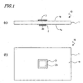
- a decorative sheet 10 in this embodiment is schematically shown in FIGS. 1(a) and (b).
- the decorative sheet 10 includes, as shown in FIGS. 1(a) and (b), a base member 1 having a first principal surface 1a and a second principal surface 1b which are opposite to each other, and a decoration layer 2 provided on the first principal surface 1a of the base member 1.
- the base member 1 is formed from a resin material, and typically formed from a thermoplastic resin material.
- the decoration layer 2 is formed from ink, or the like.
- the decoration layer 2 includes a pattern area 2a representing a predetermined pattern.
- the pattern represented by the pattern area 2a is concretely a design such as a diagram, a color-coding, or gradation, and more concretely a character shown in FIG. 2(a), a graphic symbol shown in FIG. 2(b), or a picture.
- FIGS. 1(a) and (b) show a case where the decoration layer 2 having the pattern area 2a in an entire face thereof is provided on part of the principal surface 1a.
- the decoration layer 2 having the pattern area 2a only in part may be provided on the entire face of the principal surface 1a.
- An area 2b other than the pattern area 2a of the decoration layer 2 is a monotone area without any pattern, for example.
- FIGS. 4(a) , (b) , and (c) show examples of the use of the decorative sheet 10 .
- the decorative sheet 10 is joined to the surface of a molded article body 21 , so as to decorate the molded article 20 , as shown in FIGS. 4(a) , (b) , and (c) .
- the decoration layer 2 has a pattern area 2a , so that high decorating effects can be attained, as compared with a decoration layer having no pattern area 2a (a monotone decoration layer without any pattern as a whole, for example).
- the pattern area 2a is an area of which accuracy as decoration is more highly required than the other area of the decoration layer 2 after the joining to the molded article body 21.
- the molded article body 21 shown in FIG. 4(a) has a protruding portion 21a of a hemispherical shape (a bowl-like shape), and the surface is uneven. Therefore, when the decorative sheet 10 is to be joined, the decorative sheet 10 is spread so as to follow the unevenness. In order to preferably perform the spread of the decorative sheet 10 , typically, the joining is performed after the decorative sheet 10 is heated and softened.
- the decorative sheet 10 according to the present invention is provided with a spread suppressing member 3 for suppressing the spread of the pattern area 2a, as shown in FIGS. 1(a) and (b) , and FIG. 3.
- the spread suppressing member 3 is provided in a position corresponding to the pattern area 2a.
- the spread suppressing member 3 in this embodiment is provided so as to overlap the pattern area 2a on the side of the second principal surface 1b of the base member 1 (on the side opposite to the side on which the decoration layer 2 is provided).
- the spread suppressing member 3 is a member with lower spreading property than that of the base member 1, for example, so that the spread of the pattern region 2a is suppressed.
- the spread suppressing member 3 has a higher coefficient of thermal conductivity than a coefficient of thermal conductivity of the base member 1 , so that the spread of the pattern area 2a is suppressed. If the coefficient of thermal conductivity of the spread suppressing member 3 is higher than the coefficient of thermal conductivity of the base member 1, a temperature of a portion of the decorative sheet 10 on which the spread suppressing member 3 is provided lowers more rapidly than the other portion after the heating. Thus, the spreading property is lowered as compared with the other portion. Therefore, the spreading of the pattern area 2a is suppressed.
- the spread suppressing member 3 preferably has both of the above-described two physical properties, in order to effectively suppress the spread of the pattern region 2a .
- the joining as shown in FIGS. 4(a) to (c) is performed by using a conventional decorative sheet, the pattern such as a character, a graphic symbol, or a picture is deformed, so that the beautiful appearance of the molded article is uglified.
- the decorative sheet 10 according to the present invention includes the spread suppressing member 3 , so that the spread of the pattern region 2a in joining to the molded article body 21 can be suppressed. Therefore, when the decoration of the molded article is performed by using the decorative sheet 10 according to the present invention, the deformation of the pattern can be prevented, and beautiful appearance can be attained.
- the spread suppressing member 3 is provided so as to overlap only part of the principal surface 1b of the base member 1 in accordance with the pattern area 2a (that is, provided partially with respect to the principal surface of the base member 1 ), so that the following property of the decorative sheet 10 for the unevenness of the surface of the molded article body 21 is hardly degraded.
- metal such as aluminum, copper, stainless can be preferably used.
- a foil, a film, a thin plate, or the like formed of any one of the above-mentioned metals may be preferably used.
- a coefficient of thermal conductivity of metal is higher than a coefficient of thermal conductivity of a resin by two or three digits.
- the coefficient of thermal conductivity of the spread suppressing member 3 can be sufficiently higher than the coefficient of thermal conductivity of the base member 1 formed from a resin material. Therefore, it is easy to rapidly lower the temperature of the portion of the decorative sheet 10 in which the spread suppressing member 3 is provided. Thus, it is possible to effectively suppress the spread of the pattern area 2a.
- the spread suppressing member 3 is not limited to that formed of metal. Since metal or a metal compound has a much higher coefficient of thermal conductivity than that of a resin, the coefficient of thermal conductivity of the spread suppressing member 3 can be higher than the coefficient of thermal conductivity of the base member 1 by using a material including metal or a metal compound.
- a material including metal or a metal compound for example, a material in which filler (inorganic filler) formed from metal or a metal compound is dispersedly mixed in a resin matrix is listed.
- a metal compound which constitutes filler for example, a metal oxide such as alumina can be used.
- the coefficient of thermal conductivity of the spread suppressing member 3 is preferably equal to or 50 times, and more preferably equal to or 100 times as compared with the coefficient of thermal conductivity of the base member 1.
- the coefficient of thermal conductivity of the spread suppressing member 3 is preferably 10 W/m ⁇ K or more, more preferably 15 W/m ⁇ K or more, and much more preferably 20 W/m ⁇ K.
- the coefficient of thermal conductivity of a resin material is about 0.2 (the coefficient of thermal conductivity of polycarbonate is 0.19 W/m ⁇ K, and the coefficient of thermal conductivity of acryl resin is 0.2 W/m ⁇ K, for example).
- the coefficient of thermal conductivity of alumina is 21 W/m ⁇ K, and the coefficient of thermal conductivity of aluminum is 236 W/m ⁇ K.
- a resin material can be used as the material for the spread suppressing member 3 . If a resin material having a higher deflection temperature under load (a heat deflection temperature) than that of a resin material which forms the base member 1 , or a resin material having higher rigidity than that of a resin material which forms the base member 1 , is used, the spreading property of the spread suppressing member 3 can be lower than that of the base member 1 , so that the spread of the pattern region 2a can be suppressed.
- a thickness of the spread suppressing member 3 is preferably 5 ⁇ m or more and 100 ⁇ m or less. If the thickness is lower than 5 ⁇ m, the strength is failed, and deformation or breakage may occur. If the thickness exceeds 100 ⁇ m, in the case where metal is used as the material, the following property of the spread suppressing member 3 with respect to the unevenness (convex and concave) of the molded article body 21 is sometimes insufficient. Thus, there is a fear that the spread suppressing member 3 may be peeled off in joining.
- the spread suppressing member 3 preferably has a portion which overlaps the pattern area 2a (an overlap portion) 3a.
- the spread suppressing member 3 has such an overlap portion 3a , the effect for suppressing the spread can be directly attained for the pattern area 2a .
- the spreading of the pattern area 2a can be effectively suppressed.
- the width of the outer circumference portion 3b of the spread suppressing member 3 is preferably 1 mm or more and 10 mm or less, and more preferably 2 mm or more and 8 mm or less.
- the spread suppressing member 3 does not include a portion overlapping the pattern area 2a , but has a frame-like shape fringing the pattern area 2a , the spreading of the pattern area 2a can be suppressed.
- the case where the spread suppressing member 3 has the portion 3a overlapping the pattern area 2a can attain higher effect for suppressing the spreading of the pattern area 2a.
- ink including a resin material as a binder and pigment dispersed in the resin material can be used, for example.
- the decoration layer 2 can be formed by printing with such ink.
- the material of the decoration layer 2 is preferably superior in heat resistance and flexibility.
- the ink disclosed in Japanese Laid-Open Patent Publication No.2002-275405 has superior heat resistance and flexibility, so that the ink can be preferably used as the material for the decoration layer 2 .
- thermoplastic resin material As a resin material which forms the base member 1 , a thermoplastic resin material can be suitably used, as described above. More specifically, polycarbonate (PC), acrylic resin, polyethylene terephthalate (PET), urethane resin, or the like can be preferably used. However, since the base member 1 is required to have rigidity as a sheet base member, it is preferred that a resin material be selected in consideration of this point. Although a thermosetting resin material can be used as the resin material which forms the base member 1, it is preferred that a thermoplastic resin material be used in view of the formability of the decorative sheet 10.
- a thickness of the base member 1 is preferably 100 ⁇ m or more and 1000 ⁇ m or less. If the thickness of the base member 1 is less than 100 ⁇ m, it is difficult to handle the base member as a sheet, or there may occur a disadvantageous case where the strength is not sufficient and breakage occurs in joining. If the thickness of the base member 1 exceeds 1000 ⁇ m, the following property with respect to the surface of the molded article body 21 may be deteriorated.
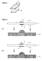
- the joining of the decorative sheet 10 may be performed, as shown in FIG. 6(a), in such a manner that the first principal surface 1a on which the decoration layer 2 is provided faces the molded article body 21, or alternatively as shown in FIG. 6(b), in such a manner that the second principal surface 1b on the opposite side to the first principal surface 1a faces the molded article body 21.
- the spread suppressing member 3 may be provided, as shown in FIGS. 6(a) and (b) , on the side of the second principal surface 1b of the base member 1 (the side on which the decoration layer 2 is not provided), or alternatively provided, as shown in FIGS. 7(a) and (b) , on the side of the first principal surface 1a of the base member 1 (the side on which the decoration layer 2 is provided).
- the spread suppressing member 3 is provided on the side of the first principal surface 1a, after the decoration layer 2 is formed on the spread suppressing member 3 by printing or other means, the accumulated body may be provided on the first principal surface 1a of the base member 1.
- the spread suppressing member 3 may be provided on both sides of the first principal surface 1a and the second principal surface 1b of the base member 1.
- the decoration layer 2 is positioned between the base member 1 and the molded article body 21 in the completed molded article, so that the decoration layer 2 can be advantageously protected by the base member 1 .
- the decoration layer 2 is positioned on the outer side than the base member 1 . Therefore, there is an advantage that in addition to a transparent resin material or a translucent resin material, an opaque resin material can be preferably used as the resin material for forming the base member 1 .
- an adhesive is used, for example.
- a thermoplastic resin thermoplastic polyurethane resin or thermoplastic acrylic resin
- a thermosetting resin an epoxy resin, for example
- the adhesive preferably has high heat resistance.
- an adhesive which has high heat resistance and which can be easily peeled off an adhesive of silicone type is listed specifically.
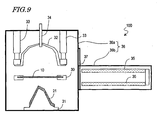
- the production apparatus 100 includes, as shown in FIG. 8 , a holding device (a holding frame) 30 for holding the decorative sheet 10 , a supporting device (a supporting table) 31 for supporting the molded article body 21 , a pressurizing box 32 positioned above the holding device 30 and the supporting device 31 , a sealing cylinder 33 for moving up and down the pressurizing box 32 , a pressurizing rubber hose 34 for introducing a gas into a space below the pressurizing box 32 , a heater (a far infrared heater, for example) 35 for heating the decorative sheet 10 , and a vacuum vessel 36 for accommodating them.
- a holding device a holding frame
- a supporting device a supporting table
- a pressurizing box 32 positioned above the holding device 30 and the supporting device 31
- a sealing cylinder 33 for moving up and down the pressurizing box 32
- a pressurizing rubber hose 34 for introducing a gas into a space below the pressurizing box 32
- a heater a far infrared
- the vacuum vessel 36 includes a first vessel 36a for accommodating the holding device 30 , the supporting device 31 , the box 32 , the cylinder 33 , and the rubber hose 34 , and a second vessel 36b for accommodating the heater 35 .
- the heater 35 may be introduced into the first vessel 36a via a door 37 , if required.
- the supporting device 31 has a plurality of openings 31a. With a vacuum pump which is externally provided, the atmospheric air is sucked through the openings 31a, thereby realizing a reduced pressure (evacuation) of the space spreading over the supporting device 31.
- the rubber hose 34 is connected to the outside. By introducing a gas through the rubber hose 34 , the space spreading below the box 32 can be pressurized.
- FIGS. 9 to 15 are process sectional views schematically showing the production method of the molded article.
- FIG. 15 is a time chart showing an example of periods of time required for respective steps.
- the decorative sheet 10 such as shown in FIG. 1 is prepared.
- the decorative sheet 10 can be prepared from the above-described materials by known techniques.
- the decorative sheet 10 can be prepared in such a manner that a decoration layer 2 is formed by printing with ink on a first principal surface 1a of a base member 1 , and a spread suppressing member 3 is fixed with an adhesive on the side of a second principal surface 1b of the base member 1.
- a molded article body 21 is prepared.
- the molded article body 21 may be formed from a resin material, or may be formed from a metal material. Alternatively, the molded article body 21 may be formed from the other materials (formed of wood, for example).
- the molded article body 21 may be transparent, opaque, or translucent.
- the molded article body 21 can be prepared by a known technique. In the case where a resin material is used, the molded article body 21 can be prepared by injection molding, for example.
- the resin material both of a thermoplastic resin and a thermosetting resin can be used. Specifically, an unsaturated polyester resin, an epoxy resin, a vinyl ester resin, a polyurethane resin, and the like can be used.
- the molded article body 21 is placed on the supporting device 31 , and the decorative sheet 10 is fixed to the holding device 30 so that the decorative sheet 10 is positioned above the molded article body 21 .
- an adhesive is applied to a surface of the decorative sheet 10 on the side of the molded article body 21 .
- the air in the vacuum vessel 35 is sucked through the openings 31a of the supporting device 31 by means of the vacuum pump which is externally provided.
- the pressure in the inside of the vacuum vessel 35 is preliminarily reduced.
- the internal pressure of the vacuum vessel 35 is 2.7 kPa or less, for example.
- the decorative sheet 10 is heated by means of the heater 35 , thereby softening the decorative sheet 10 .
- the decorative sheet 10 is typically heated up to temperatures equal to or higher than a deflection temperature under load of the resin material which forms the base member 1 . If the heating temperature is too low, it is difficult to deform the resin material. Therefore, the resin material may be broken in shaping (in attaching), or the shaping itself cannot be performed. If the heating temperature is too high, sags of sheet in heating remarkably occur, so that it is difficult to perform the shaping, or the appearance may be degraded because of air bubbles in the resin material.
- the heating temperature be appropriately set in accordance with the kind of the resin material of the base member 1 .
- the decorative sheet 10 is heated up to about 195°C, for example.
- the movement of the heater 35 from the second vessel 36b to the first vessel 36a is performed in about 3 to 5 seconds, for example.
- the heating by the heater 35 is performed for about 15 to 30 seconds, for example.
- the pressurizing box 32 and the holding device 30 are moved downwardly by the cylinder 33, so that the decorative sheet 10 comes closer to the molded article body 21 .
- the downward movement is performed in about 1 to 2 seconds, for example.
- the decorative sheet 10 is moved downwardly.
- the supporting device 31 for supporting the molded article body 21 may be moved upwardly, so that the decorative sheet 10 comes closer to the molded article body 21.
- a pressure of a first space formed between the decorative sheet 10 and the molded article body 21 is more reduced than a pressure of a second space expanded on the opposite side to the first space with respect to the decorative sheet 10 (that is, a space formed between the decorative sheet 10 and the pressurizing box 32 ).
- a pressure of a second space expanded on the opposite side to the first space with respect to the decorative sheet 10 that is, a space formed between the decorative sheet 10 and the pressurizing box 32 .
- a gas is introduced into the box 32 through the rubber hose 34 , so as to pressurize the second space.
- the pressure reduction in the first space is performed, so that the internal pressure of the first space is 2.7 kPa or less, for example.
- the pressurizing of the second space is performed, so that the internal pressure of the second space is about 0.2 MPa to 0.5 MPa.
- the reduced pressure condition of the first space and the pressurized condition of the second space are retained for a predetermined period of time (for 15 seconds or more, for example).
- a temperature of the gas (the air, for example) introduced into the second space is about a room temperature (15°C to 30°C), for example.
- the vacuum vessel 35 is opened, so that the internal pressure of the vacuum vessel 35 is returned to be the atmospheric pressure. Unnecessary portions of the decorative sheet 10 are cut (trimmed) with cutting means such as a rotary blade. Thereafter, the molded article body 21 is released from the supporting device 30 , thereby completing a molded article 20 , as shown in FIG. 14 .
- the decorative sheet 10 is entirely spread, but the spreading of the pattern portion 2a of the decoration layer 2 is suppressed by means of the spread suppressing member 3 . Therefore, the distortion of pattern is prevented, and the beauty in appearance is not deteriorated.
- the spreading property of the spread suppressing member 3 is poorer than the spreading property of the base member 1 , the spreading of the pattern portion 2a is suppressed for this reason.
- the coefficient of thermal conductivity of the spread suppressing member 3 is higher than the coefficient of thermal conductivity of the base member 1 , the temperature of the portion of the decorative sheet 10 in which the spread suppressing member 3 is provided (that is, the portion corresponding to the pattern area 2a) more rapidly lowers than the temperature of the other portion of the decorative sheet 10. Therefore, the joining of the decorative sheet 10 is performed in a condition where the temperature of the portion of the decorative sheet 10 corresponding to the pattern area 2a is lower than the temperature of the other portion of the decorative sheet 10 . Therefore, the spreading of the pattern portion 2a is suppressed.
- the decorative sheet 10 is naturally cooled (allowed to cool). As a result, the above-described non-uniform temperature distribution of the decorative sheet 10 can be realized.
- more positive cooling may be performed.
- the gas is introduced into the second space in joining, as in this embodiment, the introduced gas can not only pressurize the second space, but also cool the surface of the decorative sheet 10 on the side of the second space. Therefore, when the spread suppressing member 3 faces the second space, the spread suppressing member 3 is cooled by the gas, so that the above-described non-uniform temperature distribution can be rapidly realized. Therefore, even in the case where the joining is performed in a very short time as described above, the spreading of the pattern area 2a can be more surely suppressed.
- the spread suppressing member 3 may be removed from the molded article 20 if necessary. If the fixing of the spread suppressing member 3 is performed by means of an adhesive which can be easily peeled off, the removal can be preferably performed.
- FIG. 16 is a partially enlarged view of an example of the sectional structure after the joining.
- a protecting layer 8 of an acrylic resin is formed on the second principal surface 1b of the base member 1 formed from polycarbonate.
- the spread suppressing member 3 formed of aluminum is provided with the adhesive layer 9 interposed therebetween.
- the protecting layer 8 is positioned on the outer side than the base member 1 in the molded article 20 , so that the protecting layer 8 protects the base member 1 and improves the weather resistance of the decorative sheet 10 .
- the base member 1 has a thickness of 200 ⁇ m to 1000 ⁇ m, for example.
- the protecting layer 8 has a thickness of 5 ⁇ m to 50 ⁇ m, for example.
- the spread suppressing member 3 has a thickness of 5, ⁇ m to 100 ⁇ mm, for example.
- the adhesive layer 9 has a thickness of 5 ⁇ m to 50 ⁇ m, for example.
- the decoration layer 2 formed of ink is provided on the first principal surface 1a of the base member 1.
- a metal layer 6 formed from tin is provided with the adhesive layer 7 interposed therebetween. Since the metal layer 6 has metallic luster, the decorative sheet 10 can exhibit colors of metallic tones (metallic color) having metallic appearance.
- the metal layer 6 is formed in such a manner that tin is evaporated on a carrier film 5, and the layered body is attached to the first principal surface 1a with an adhesive.
- the decoration layer 2 has a thickness of 5 ⁇ m to 50 ⁇ m, for example.
- the metal layer 6 has a thickness of 0.25 ⁇ m to 0.8 ⁇ m, for example, and is formed from soft metal such as tin.
- the decorative sheet 10 shown in FIG. 16 is joined to the molded article body 21 by means of the adhesive layer 4.
- the adhesive layer 4 has a thickness of 5 ⁇ m to 50 ⁇ m, for example.
- the spread suppressing member 3 may be provided on the side of the first principal surface 1a of the base member 1. More specifically, as shown by a dot line in FIG. 16, on the first principal surface 1a of the base member 1, the spread suppressing member 3 may be provided with the decoration layer 2 , the adhesive layer 7 , the metal layer 6 , and the carrier film 5 interposed therebetween.
- the thickness T 1 of the portion of the sheet 10 corresponding to the pattern area 2a is preferably 1.1 times or more and 1.8 times or less as large as the thickness T 2 of the other portion of the sheet 10. More preferably, the thickness T 1 is 1.2 times or more and 1.6 time or less as large as the thickness T 2 .
- the pattern area 2a is such thin that the thickness T 1 is less than 1.1 times as large as the thickness T 2 , stepped cut may occur in the pattern area 2a due to the unevenness of the surface of the molded article body 21 , and desired decorating effects cannot be attained.
- the appearance of the pattern area 2a may be distorted due to the lens effect, or the portion corresponding to the pattern area 2a (the portion is raised as compared with the other portion) may get scratched by friction.
- the molded article body 21 which is integrally formed (in other words, which has a single member) is shown.
- a molded article may have a plurality of members which are separately molded, and the plurality of members may be mutually coupled by the joining of the decorative sheet 10.
- the decorative sheet 10 is joined so as to cover both of the first member 22a and the second member 22b .
- a molded article 20' in which the first member 22a and the second member 22b are coupled can be obtained.
- a relative positional relationship between the first member 22a and the second member 22b can be arbitrarily selected. For this reason, when the plurality of members 22a and 22b of the molded article body 22 are coupled by means of the joining of the decorative sheet 10 , as described above, a large variety of shapes of molded articles can be obtained by using a relatively small number of molding dies. Therefore, the production of the large variety of shapes of molded articles can be easily performed at a low cost.
- a structure for temporarily tacking them that is, a positioning structure for determining the relative positional relationship can be provided.
- the positioning structure may be a protruding portion and a concave portion which are mutually engaged, for example.
- the molded article produced by the production method using the decorative sheet 10 is suitably used for interior or exterior of motor vehicles, exterior of home electric appliances, and the like.
- the molded article is suitably used as a tank cover 51 , a front fender 52 , and a tail cowl 53 of a motorbike 50 shown in FIG. 19 .
- the "motor vehicles” widely indicate loco mobile conveyances or machines for transporting passengers or merchandises, or for moving things, and include a car, a motorbike, a bus, a truck, a tractor, an airplane, a motorboat, a civil engineering vehicle, and the like.
- the motor vehicles include not only those provided with an internal combustion engine such as a gasoline engine, but also those provided with an electric motor.
- the spread suppressing member for suppressing the spreading of the pattern area is provided in a position corresponding to the pattern area of the decoration layer, the spreading of the pattern area in the joining to the molded article body can be suppressed. Accordingly, the decorative sheet according to the present invention can be preferably used for the decoration of a molded article of which the surface has unevenness. When the production of the molded article is performed by using the decorative sheet according to the present invention, distortion of pattern can be prevented, and the obtained molded article has beautiful appearance.
- the molded article which is produced by using the decorative sheet according to the present invention is preferably used for various goods, and especially preferably used for interior and exterior of a motor vehicle.
Abstract
Description
- The present invention relates to a molded article which is decorated, and a production method thereof. The present invention also relates to a decorative sheet used for decorating such a molded article, and a motor vehicle provided with such a molded article.
- Recently, as a technique for decorating various kinds of molded articles, a technique for attaching a decorative sheet onto a surface of a molded article is proposed. The decorative sheet used in this technique is disclosed in Japanese Laid-Open Patent Publication No.10-249999, for example.
- The decorative sheet disclosed in the above-identified publication includes a base member and an ink layer formed on a surface of the base member by printing. The decorative sheet is attached to a molded article with an adhesive. When such a decorative sheet is used, the molded article can be easily recycled as compared with the case of paint application using a coating material. In addition, such a decorative sheet can create beautiful appearance which is different from the paint application, so that a decorative quality can be improved.
- A conventional decorative sheet is, however, suitable for the decoration of a molded article having a flat surface, but is not suitable for the decoration of a molded article having an uneven surface. When such a decorative sheet is attached to a molded article having an uneven surface, the decorative sheet is spread so as to follow the unevenness. Therefore, if a pattern of a character, a graphic symbol, a picture, and the like is represented in part of the decorative sheet, the pattern is deformed, and the decorative appearance is uglified.
- The present invention has been conducted in view of the above-described problems, and the object of the present invention is to provide a decorative sheet preferably used for the decoration of a molded article having an uneven surface, a molded article to which the decorative sheet is attached, a production method thereof, and a motor vehicle provided with such a molded article.
- The decorative sheet of the present invention includes: a base member, formed from a resin material, having a first and a second principal surfaces opposite to each other; a decoration layer, provided on the first principal surface of the base member, having a pattern area representing a predetermined pattern; and a spread suppressing member, provided in a position corresponding to the pattern area on the side of the first principal surface or on the side of the second principal surface of the base member, for suppressing the spreading of the pattern area of the decoration layer, thereby attaining the above-mentioned object.
- In one preferred embodiment, the resin material is a thermoplastic resin material.
- In one preferred embodiment, the spread suppressing member has a higher coefficient of thermal conductivity than a coefficient of thermal conductivity of the base member.
- In one preferred embodiment, the spread suppressing member is formed from a material including metal or a metal compound.
- In one preferred embodiment, the spread suppressing member is formed of metal.
- In one preferred embodiment, a coefficient of thermal conductivity of the spread suppressing member is 10 W/m· K or more.
- Preferably, a thickness of the spread suppressing member is 5 µ m or more and 100 µ m or less.
- Preferably, the spread suppressing member includes a first portion which overlaps the pattern area.
- More preferably, the spread suppressing member includes a second portion positioned in an outer circumference of the first portion.
- Preferably, a width of the second portion of the spread suppressing member is 1 mm or more and 10 mm or less.
- More preferably, a width of the second portion of the spread suppressing member is 2 mm or more and 8 mm or less.
- The molded article according to the present invention includes a molded article body and the decorative sheet with the above-described structure which is joined to a surface of the molded article body, thereby attaining the above-mentioned object.
- In another aspect, the molded article according to the present invention includes: a molded article body; and a sheet joined to a surface of the molded article body, wherein the sheet includes a base member and a decoration layer provided on a face of the base member on the side of the molded article body, the decoration layer has a pattern area representing a predetermined pattern, and a portion of the sheet corresponding to the pattern area has a thickness which is 1.1 times or more and 1.8 times or less as large as a thickness of the other portion of the sheet, thereby attaining the above-mentioned object.
- Preferably, the portion of the sheet corresponding to the pattern area has a thickness which is 1.2 times or more and 1.6 times or less as large as the thickness of the other portion of the sheet.
- The motor vehicle according to the present invention includes the molded article having the above-described structure, thereby attaining the above-mentioned object.
- The production method of a molded article according to the present invention includes the steps of: preparing a decorative sheet including: a base member, formed from a resin material, having a first and a second principal surfaces opposite to each other; a decoration layer, provided on the first principal surface of the base member, having a pattern area representing a predetermined pattern; and a spread suppressing member, provided in a position corresponding to the pattern area on the side of the first principal surface or on the side of the second principal surface of the base member, for suppressing the spreading of the pattern area of the decoration layer; preparing a molded article body; and joining the decorative sheet to a surface of the molded article body, thereby attaining the above-mentioned object.
- In one preferred embodiment, the production method of a molded article according to the present invention includes, before the step of joining the decorative sheet to the surface of the molded article body, the step of heating the decorative sheet.
- In one preferred embodiment, the resin material is a thermoplastic resin material.
- In one preferred embodiment, the spread suppressing member has a higher coefficient of thermal conductivity than a coefficient of thermal conductivity of the base member.
- In one preferred embodiment, the spread suppressing member is formed form a material including metal or a metal compound.
- In one preferred embodiment, the spread suppressing member is formed of metal.
- In one preferred embodiment, the coefficient of thermal conductivity of the spread suppressing member is 10 W/m· K or more.
- Preferably, a thickness of the spread suppressing member is 5 µ m or more and 100 µ m or less.
- Preferably, the spread suppressing member has a first portion which overlaps the pattern area.
- More preferably, the spread suppressing member includes a second portion positioned in an outer circumference of the first portion.
- Preferably, a width of the second portion of the spread suppressing member is 1 mm or more and 10 mm or less.
- More preferably, a width of the second portion of the spread suppressing member is 2 mm or more and 8 mm or less.
- In one preferred embodiment, the step of joining the decorative sheet to the surface of the molded article body includes the step of moving the heated decorative sheet closer to the molded article body, and the step of reducing a pressure of a first space formed between the decorative sheet coming closer to the molded article body and the molded article body as compared with a pressure of a second space expanded oppositely to the first space with respect to the decorative sheet.
- In one preferred embodiment, the step of moving the decorative sheet closer to the molded article body is performed in such a manner that the spread suppressing member faces the second space.
- In one preferred embodiment, in the production method of a molded article according to the present invention includes, after the step of moving the decorative sheet closer to the molded body, the step of cooling the spread suppressing member by introducing a gas into the second space.
- In one preferred embodiment, the production method of a molded article according to the present invention includes, after the step of joining the decorative sheet to the surface of the molded body, the step of removing the spread suppressing member.
- In one preferred embodiment, the spread suppressing member is provided on the side of the second principal surface of the base member.
- In one preferred embodiment, after the step of joining the decorative sheet to the surface of the molded article body, the decoration layer is positioned between the base member and the molded article body.
- In one preferred embodiment, the molded article body includes a first member and a second member disposed on a surface of the first member, and in the step of joining the decorative sheet to the surface of the molded article body, the decorative sheet is joined to the surface of the molded article body so as to cover both of the first member and the second member, thereby joining the first member and the second member.
- In another aspect, the production method of a molded article according to the present invention includes the steps of: preparing a decorative sheet including a base member, formed from a resin material, having a first and a second principal surfaces opposite to each other, and a decoration layer, provided on the first principal surface of the base member, having a pattern area representing a predetermined pattern; preparing a molded article body; heating the decorative sheet; and joining the decorative sheet which is heated to a surface of the molded article body in a condition where a temperature of a portion of the decorative sheet corresponding to the pattern area is lower than a temperature of the other portion of the decorative sheet, thereby attaining the above-mentioned object.
- In one preferred embodiment, the step of joining the decorative sheet to the surface of the molded article body includes the step of cooling the decorative sheet in such a manner that the temperature of the portion corresponding to the pattern area is rapidly lowered as compared with the temperature of the other portion.
- In one preferred embodiment, the decorative sheet further includes a member, provided in a position corresponding to the pattern area on the side of the first principal surface or on the side of the second principal surface of the base member, having a higher coefficient of thermal conductivity than a coefficient of thermal conductivity of the base member.
- In one preferred embodiment, the member is formed from a material including metal.
- In one preferred embodiment, the member is formed of metal.
- In one preferred embodiment, a coefficient of thermal conductivity of the member is 10 W/m· K or more.
- The motor vehicle according to the present invention includes the molded article produced by the above-described production method, thereby attaining the above-mentioned object.
-
- FIG. 1(a) is a sectional view schematically showing a decorative sheet according to the present invention, and FIG. 1(b) is a top view schematically showing the decorative sheet according to the present invention.
- FIGS. 2(a) and (b) are views showing exemplary patterns represented by a pattern area of a decoration layer.
- FIG. 3 is a sectional view schematically showing another embodiment of a decorative sheet according to the present invention.
- FIGS. 4(a), (b), and (c) are views schematically showing one embodiment of the use of the decorative sheet according to the present invention.
- FIG. 5 is a view schematically showing a preferred structure of a spread suppressing member.
- FIGS. 6(a) and (b) are views schematically showing an embodiment in which the decorative sheet according to the present invention is joined to a molded article body.
- FIGS. 7(a)and (b) are views schematically showing another embodiment in which the decorative sheet according to the present invention is joined to a molded article.
- FIG. 8 is a sectional view schematically showing a producing apparatus used for producing a molded article with the decorative sheet according to the present invention.
- FIG. 9 is a process sectional view schematically showing a production method of a molded article with the decorative sheet according to the present invention.
- FIG. 10 is a process sectional view schematically showing a production method of a molded article with the decorative sheet according to the present invention.
- FIG. 11 is a process sectional view schematically showing a production method of a molded article with the decorative sheet according to the present invention.
- FIG. 12 is a process sectional view schematically showing a production method of a molded article with the decorative sheet according to the present invention.
- FIG. 13 is a process sectional view schematically showing a production method of a molded article with the decorative sheet according to the present invention.
- FIG. 14 is a process sectional view schematically showing a production method of a molded article with the decorative sheet according to the present invention.
- FIG. 15 is a time chart showing an exemplary time required for a production process.
- FIG. 16 is a sectional view schematically showing a molded article.
- FIG. 17 is a sectional view schematically showing a molded article.
- FIG. 18(a) and (b) are sectional views schematically showing a condition where a decorative sheet is joined to a molded article body having a plurality of members which are separately molded.
- FIG. 19 is a view schematically showing a two-wheeled vehicle.
-
- Hereinafter embodiments of the present invention will be described with reference to the accompanying drawings. The present invention is not limited to the embodiments described below.
- A
decorative sheet 10 in this embodiment is schematically shown in FIGS. 1(a) and (b). Thedecorative sheet 10 includes, as shown in FIGS. 1(a) and (b), abase member 1 having a firstprincipal surface 1a and a secondprincipal surface 1b which are opposite to each other, and adecoration layer 2 provided on the firstprincipal surface 1a of thebase member 1. - The
base member 1 is formed from a resin material, and typically formed from a thermoplastic resin material. Thedecoration layer 2 is formed from ink, or the like. Thedecoration layer 2 includes apattern area 2a representing a predetermined pattern. The pattern represented by thepattern area 2a is concretely a design such as a diagram, a color-coding, or gradation, and more concretely a character shown in FIG. 2(a), a graphic symbol shown in FIG. 2(b), or a picture. - FIGS. 1(a) and (b) show a case where the
decoration layer 2 having thepattern area 2a in an entire face thereof is provided on part of theprincipal surface 1a. Alternatively, as shown in FIG. 3, thedecoration layer 2 having thepattern area 2a only in part may be provided on the entire face of theprincipal surface 1a. Anarea 2b other than thepattern area 2a of thedecoration layer 2 is a monotone area without any pattern, for example. - FIGS. 4(a), (b), and (c) show examples of the use of the
decorative sheet 10. Thedecorative sheet 10 is joined to the surface of a moldedarticle body 21, so as to decorate the moldedarticle 20, as shown in FIGS. 4(a), (b), and (c). Thedecoration layer 2 has apattern area 2a, so that high decorating effects can be attained, as compared with a decoration layer having nopattern area 2a (a monotone decoration layer without any pattern as a whole, for example). In other words, thepattern area 2a is an area of which accuracy as decoration is more highly required than the other area of thedecoration layer 2 after the joining to the moldedarticle body 21. - The molded
article body 21 shown in FIG. 4(a) has a protrudingportion 21a of a hemispherical shape (a bowl-like shape), and the surface is uneven. Therefore, when thedecorative sheet 10 is to be joined, thedecorative sheet 10 is spread so as to follow the unevenness. In order to preferably perform the spread of thedecorative sheet 10, typically, the joining is performed after thedecorative sheet 10 is heated and softened. - The
decorative sheet 10 according to the present invention is provided with aspread suppressing member 3 for suppressing the spread of thepattern area 2a, as shown in FIGS. 1(a) and (b), and FIG. 3. Thespread suppressing member 3 is provided in a position corresponding to thepattern area 2a. Thespread suppressing member 3 in this embodiment is provided so as to overlap thepattern area 2a on the side of the secondprincipal surface 1b of the base member 1 (on the side opposite to the side on which thedecoration layer 2 is provided). - The
spread suppressing member 3 is a member with lower spreading property than that of thebase member 1, for example, so that the spread of thepattern region 2a is suppressed. - Alternatively, the
spread suppressing member 3 has a higher coefficient of thermal conductivity than a coefficient of thermal conductivity of thebase member 1, so that the spread of thepattern area 2a is suppressed. If the coefficient of thermal conductivity of thespread suppressing member 3 is higher than the coefficient of thermal conductivity of thebase member 1, a temperature of a portion of thedecorative sheet 10 on which thespread suppressing member 3 is provided lowers more rapidly than the other portion after the heating. Thus, the spreading property is lowered as compared with the other portion. Therefore, the spreading of thepattern area 2a is suppressed. - It is understood that the
spread suppressing member 3 preferably has both of the above-described two physical properties, in order to effectively suppress the spread of thepattern region 2a. - If the joining as shown in FIGS. 4(a) to (c) is performed by using a conventional decorative sheet, the pattern such as a character, a graphic symbol, or a picture is deformed, so that the beautiful appearance of the molded article is uglified.
- On the contrary, the
decorative sheet 10 according to the present invention includes thespread suppressing member 3, so that the spread of thepattern region 2a in joining to the moldedarticle body 21 can be suppressed. Therefore, when the decoration of the molded article is performed by using thedecorative sheet 10 according to the present invention, the deformation of the pattern can be prevented, and beautiful appearance can be attained. Thespread suppressing member 3 is provided so as to overlap only part of theprincipal surface 1b of thebase member 1 in accordance with thepattern area 2a (that is, provided partially with respect to the principal surface of the base member 1), so that the following property of thedecorative sheet 10 for the unevenness of the surface of the moldedarticle body 21 is hardly degraded. - Hereinafter, preferable materials, structures, and layouts of the
spread suppressing member 3, thedecoration layer 2, and thebase member 1 will be described. - As a material for the
spread suppressing member 3, metal such as aluminum, copper, stainless can be preferably used. As thespread suppressing member 3, a foil, a film, a thin plate, or the like formed of any one of the above-mentioned metals may be preferably used. Generally, a coefficient of thermal conductivity of metal is higher than a coefficient of thermal conductivity of a resin by two or three digits. For this reason, if metal is used as the material for thespread suppressing member 3, the coefficient of thermal conductivity of thespread suppressing member 3 can be sufficiently higher than the coefficient of thermal conductivity of thebase member 1 formed from a resin material. Therefore, it is easy to rapidly lower the temperature of the portion of thedecorative sheet 10 in which thespread suppressing member 3 is provided. Thus, it is possible to effectively suppress the spread of thepattern area 2a. - The
spread suppressing member 3 is not limited to that formed of metal. Since metal or a metal compound has a much higher coefficient of thermal conductivity than that of a resin, the coefficient of thermal conductivity of thespread suppressing member 3 can be higher than the coefficient of thermal conductivity of thebase member 1 by using a material including metal or a metal compound. As a material including metal or a metal compound, for example, a material in which filler (inorganic filler) formed from metal or a metal compound is dispersedly mixed in a resin matrix is listed. As a metal compound which constitutes filler, for example, a metal oxide such as alumina can be used. - In order to rapidly lower the temperature of the portion of the
decorative sheet 10 in which thespread suppressing member 3 is provided, and to effectively suppress the spread of thepattern region 2a, the coefficient of thermal conductivity of thespread suppressing member 3 is preferably equal to or 50 times, and more preferably equal to or 100 times as compared with the coefficient of thermal conductivity of thebase member 1. Specifically, the coefficient of thermal conductivity of thespread suppressing member 3 is preferably 10 W/m · K or more, more preferably 15 W/m· K or more, and much more preferably 20 W/m· K. The coefficient of thermal conductivity of a resin material is about 0.2 (the coefficient of thermal conductivity of polycarbonate is 0.19 W/m· K, and the coefficient of thermal conductivity of acryl resin is 0.2 W/m · K, for example). On the contrary, the coefficient of thermal conductivity of alumina is 21 W/m · K, and the coefficient of thermal conductivity of aluminum is 236 W/m · K. - Alternatively, as the material for the
spread suppressing member 3, a resin material can be used. If a resin material having a higher deflection temperature under load (a heat deflection temperature) than that of a resin material which forms thebase member 1, or a resin material having higher rigidity than that of a resin material which forms thebase member 1, is used, the spreading property of thespread suppressing member 3 can be lower than that of thebase member 1, so that the spread of thepattern region 2a can be suppressed. - A thickness of the
spread suppressing member 3 is preferably 5 µm or more and 100 µ m or less. If the thickness is lower than 5 µm, the strength is failed, and deformation or breakage may occur. If the thickness exceeds 100 µ m, in the case where metal is used as the material, the following property of thespread suppressing member 3 with respect to the unevenness (convex and concave) of the moldedarticle body 21 is sometimes insufficient. Thus, there is a fear that thespread suppressing member 3 may be peeled off in joining. - As shown in FIG. 5, the
spread suppressing member 3 preferably has a portion which overlaps thepattern area 2a (an overlap portion) 3a. When thespread suppressing member 3 has such anoverlap portion 3a, the effect for suppressing the spread can be directly attained for thepattern area 2a. Thus, the spreading of thepattern area 2a can be effectively suppressed. - As shown in the figure, when the
spread suppressing member 3 also has aportion 3b which is positioned in an outer circumference of theoverlap portion 3a (an outer circumference portion), the spreading of thepattern area 2a can be more surely suppressed. From the point of view that the spreading of thepattern area 2a is effectively suppressed, and the spreading of the portion other than thepattern area 2a is not prevented, the width of theouter circumference portion 3b of thespread suppressing member 3 is preferably 1 mm or more and 10 mm or less, and more preferably 2 mm or more and 8 mm or less. - Even if the
spread suppressing member 3 does not include a portion overlapping thepattern area 2a, but has a frame-like shape fringing thepattern area 2a, the spreading of thepattern area 2a can be suppressed. However, as shown in FIG. 5, the case where thespread suppressing member 3 has theportion 3a overlapping thepattern area 2a can attain higher effect for suppressing the spreading of thepattern area 2a. - As a material of the
decoration layer 2, ink including a resin material as a binder and pigment dispersed in the resin material can be used, for example. Thedecoration layer 2 can be formed by printing with such ink. The material of thedecoration layer 2 is preferably superior in heat resistance and flexibility. The ink disclosed in Japanese Laid-Open Patent Publication No.2002-275405 has superior heat resistance and flexibility, so that the ink can be preferably used as the material for thedecoration layer 2. - As a resin material which forms the
base member 1, a thermoplastic resin material can be suitably used, as described above. More specifically, polycarbonate (PC), acrylic resin, polyethylene terephthalate (PET), urethane resin, or the like can be preferably used. However, since thebase member 1 is required to have rigidity as a sheet base member, it is preferred that a resin material be selected in consideration of this point. Although a thermosetting resin material can be used as the resin material which forms thebase member 1, it is preferred that a thermoplastic resin material be used in view of the formability of thedecorative sheet 10. - A thickness of the
base member 1 is preferably 100 µ m or more and 1000 µ m or less. If the thickness of thebase member 1 is less than 100 µ m, it is difficult to handle the base member as a sheet, or there may occur a disadvantageous case where the strength is not sufficient and breakage occurs in joining. If the thickness of thebase member 1 exceeds 1000 µ m, the following property with respect to the surface of the moldedarticle body 21 may be deteriorated. - The joining of the
decorative sheet 10 may be performed, as shown in FIG. 6(a), in such a manner that the firstprincipal surface 1a on which thedecoration layer 2 is provided faces the moldedarticle body 21, or alternatively as shown in FIG. 6(b), in such a manner that the secondprincipal surface 1b on the opposite side to the firstprincipal surface 1a faces the moldedarticle body 21. - The
spread suppressing member 3 may be provided, as shown in FIGS. 6(a) and (b), on the side of the secondprincipal surface 1b of the base member 1 (the side on which thedecoration layer 2 is not provided), or alternatively provided, as shown in FIGS. 7(a) and (b), on the side of the firstprincipal surface 1a of the base member 1 (the side on which thedecoration layer 2 is provided). In the case where thespread suppressing member 3 is provided on the side of the firstprincipal surface 1a, after thedecoration layer 2 is formed on thespread suppressing member 3 by printing or other means, the accumulated body may be provided on the firstprincipal surface 1a of thebase member 1. Alternatively, thespread suppressing member 3 may be provided on both sides of the firstprincipal surface 1a and the secondprincipal surface 1b of thebase member 1. - As shown in FIG. 6(a) and FIG. 7(a), when the joining is performed in such a manner that the first
principal surface 1a on which thedecoration layer 2 is provided faces the moldedarticle body 21, thedecoration layer 2 is positioned between thebase member 1 and the moldedarticle body 21 in the completed molded article, so that thedecoration layer 2 can be advantageously protected by thebase member 1. - On the other hand, as shown in FIG. 6(b) and FIG. 7(b), when the joining is performed in such a manner that the second
principal surface 1b faces the moldedarticle body 21, thedecoration layer 2 is positioned on the outer side than thebase member 1. Therefore, there is an advantage that in addition to a transparent resin material or a translucent resin material, an opaque resin material can be preferably used as the resin material for forming thebase member 1. - As shown in FIG. 6(a) and FIG. 7(b), when the joining is performed in such a manner that the
spread suppressing member 3 is positioned on the side opposite to the moldedarticle body 21 with respect to thebase member 1, it is possible to remove thespread suppressing member 3 after the joining. It is possible to prevent the beautiful appearance from being deteriorated because thespread suppressing member 3 remains in the completed molded article. In addition, it is possible to neglect the contribution of thespread suppressing member 3 to decoration in the completed molded article, so that the material for thespread suppressing member 3 can be more freely selected (it is unnecessary to use a transparent or translucent material, for example). Thus, it is possible to preferably use various materials such as metal. - Especially when the
spread suppressing member 3 is provided on the side of the secondprincipal surface 1b of the base member 1 (on the side opposite to the side on which thedecoration layer 2 is provided), and the joining is performed in such a manner that the firstprincipal surface 1a on which thedecoration layer 2 is provided faces the moldedarticle body 21, as shown in FIG. 6(a), both of the advantages that thedecoration layer 2 can be protected by thebase member 1 and that it is possible to remove thespread suppressing member 3. Thus, large merits in practical use can be attained. - For the fixing of the
spread suppressing member 3 and thedecorative sheet 10, an adhesive is used, for example. As an adhesive, a thermoplastic resin (thermoplastic polyurethane resin or thermoplastic acrylic resin) can be used, or a thermosetting resin (an epoxy resin, for example) can be used. When thedecorative sheet 10 is heated before the joining, the adhesive preferably has high heat resistance. In the case where thespread suppressing member 3 is removed after the joining, it is preferred that the adhesive used for joining thespread suppressing member 3 be easily peeled off. As an adhesive which has high heat resistance and which can be easily peeled off, an adhesive of silicone type is listed specifically. - Next, a production method of a molded article using the
decorative sheet 10 and a production apparatus used in the production method will be described. - First, a
production apparatus 100 for the molded article is described with reference to FIG. 8. Theproduction apparatus 100 includes, as shown in FIG. 8, a holding device (a holding frame) 30 for holding thedecorative sheet 10, a supporting device (a supporting table) 31 for supporting the moldedarticle body 21, apressurizing box 32 positioned above the holdingdevice 30 and the supportingdevice 31, a sealingcylinder 33 for moving up and down thepressurizing box 32, a pressurizingrubber hose 34 for introducing a gas into a space below thepressurizing box 32, a heater (a far infrared heater, for example) 35 for heating thedecorative sheet 10, and avacuum vessel 36 for accommodating them. - The
vacuum vessel 36 includes afirst vessel 36a for accommodating the holdingdevice 30, the supportingdevice 31, thebox 32, thecylinder 33, and therubber hose 34, and asecond vessel 36b for accommodating theheater 35. Theheater 35 may be introduced into thefirst vessel 36a via adoor 37, if required. - The supporting
device 31 has a plurality ofopenings 31a. With a vacuum pump which is externally provided, the atmospheric air is sucked through theopenings 31a, thereby realizing a reduced pressure (evacuation) of the space spreading over the supportingdevice 31. Therubber hose 34 is connected to the outside. By introducing a gas through therubber hose 34, the space spreading below thebox 32 can be pressurized. - Next, with reference to FIGS. 9 to 15, a production method of a molded article utilizing the
decorative sheet 10 will be described. FIGS. 9 to 14 are process sectional views schematically showing the production method of the molded article. FIG. 15 is a time chart showing an example of periods of time required for respective steps. - First, the
decorative sheet 10 such as shown in FIG. 1 is prepared. Thedecorative sheet 10 can be prepared from the above-described materials by known techniques. For example, thedecorative sheet 10 can be prepared in such a manner that adecoration layer 2 is formed by printing with ink on a firstprincipal surface 1a of abase member 1, and aspread suppressing member 3 is fixed with an adhesive on the side of a secondprincipal surface 1b of thebase member 1. - In a separate step from the step of preparing the
decorative sheet 10, a moldedarticle body 21 is prepared. The moldedarticle body 21 may be formed from a resin material, or may be formed from a metal material. Alternatively, the moldedarticle body 21 may be formed from the other materials (formed of wood, for example). The moldedarticle body 21 may be transparent, opaque, or translucent. The moldedarticle body 21 can be prepared by a known technique. In the case where a resin material is used, the moldedarticle body 21 can be prepared by injection molding, for example. As the resin material, both of a thermoplastic resin and a thermosetting resin can be used. Specifically, an unsaturated polyester resin, an epoxy resin, a vinyl ester resin, a polyurethane resin, and the like can be used. - Next, as shown in FIG. 9, the molded
article body 21 is placed on the supportingdevice 31, and thedecorative sheet 10 is fixed to the holdingdevice 30 so that thedecorative sheet 10 is positioned above the moldedarticle body 21. At this time, an adhesive is applied to a surface of thedecorative sheet 10 on the side of the moldedarticle body 21. In this embodiment, thereafter, the air in thevacuum vessel 35 is sucked through theopenings 31a of the supportingdevice 31 by means of the vacuum pump which is externally provided. Thus, the pressure in the inside of thevacuum vessel 35 is preliminarily reduced. As the result of the pressure reduction, the internal pressure of thevacuum vessel 35 is 2.7 kPa or less, for example. - Next, as shown in FIG. 10, the
decorative sheet 10 is heated by means of theheater 35, thereby softening thedecorative sheet 10. At this time, thedecorative sheet 10 is typically heated up to temperatures equal to or higher than a deflection temperature under load of the resin material which forms thebase member 1. If the heating temperature is too low, it is difficult to deform the resin material. Therefore, the resin material may be broken in shaping (in attaching), or the shaping itself cannot be performed. If the heating temperature is too high, sags of sheet in heating remarkably occur, so that it is difficult to perform the shaping, or the appearance may be degraded because of air bubbles in the resin material. Therefore, it is preferred that the heating temperature be appropriately set in accordance with the kind of the resin material of thebase member 1. When polycarbonate is used as the resin material for forming thebase member 1, thedecorative sheet 10 is heated up to about 195°C, for example. The movement of theheater 35 from thesecond vessel 36b to thefirst vessel 36a is performed in about 3 to 5 seconds, for example. The heating by theheater 35 is performed for about 15 to 30 seconds, for example. - Thereafter, as shown in FIG. 11, the
pressurizing box 32 and the holdingdevice 30 are moved downwardly by thecylinder 33, so that thedecorative sheet 10 comes closer to the moldedarticle body 21. The downward movement is performed in about 1 to 2 seconds, for example. In this embodiment, thedecorative sheet 10 is moved downwardly. Alternatively, the supportingdevice 31 for supporting the moldedarticle body 21 may be moved upwardly, so that thedecorative sheet 10 comes closer to the moldedarticle body 21. - Next, as shown in FIG. 12, a pressure of a first space formed between the
decorative sheet 10 and the moldedarticle body 21 is more reduced than a pressure of a second space expanded on the opposite side to the first space with respect to the decorative sheet 10 (that is, a space formed between thedecorative sheet 10 and the pressurizing box 32). As a result, thedecorative sheet 10 is joined to the moldedarticle body 21, as shown in FIG. 13. - Specifically, together with the reduction of pressure in the first space by means of the vacuum pump, a gas is introduced into the
box 32 through therubber hose 34, so as to pressurize the second space. As a result, thedecorative sheet 10 is pressed against the moldedarticle body 21 with a substantially uniform pressure, thereby joining thedecorative sheet 10 to the moldedarticle body 21. The pressure reduction in the first space is performed, so that the internal pressure of the first space is 2.7 kPa or less, for example. The pressurizing of the second space is performed, so that the internal pressure of the second space is about 0.2 MPa to 0.5 MPa. The reduced pressure condition of the first space and the pressurized condition of the second space are retained for a predetermined period of time (for 15 seconds or more, for example). A temperature of the gas (the air, for example) introduced into the second space is about a room temperature (15°C to 30°C), for example. - Next, the
vacuum vessel 35 is opened, so that the internal pressure of thevacuum vessel 35 is returned to be the atmospheric pressure. Unnecessary portions of thedecorative sheet 10 are cut (trimmed) with cutting means such as a rotary blade. Thereafter, the moldedarticle body 21 is released from the supportingdevice 30, thereby completing a moldedarticle 20, as shown in FIG. 14. - According to the above-described production method, it is possible to perform the joining of the
decorative sheet 10 to the molded article body 21 (that is, the figuration of the decorative sheet 10) in a very short period of time (in 1 second or less, as exemplarily described). In addition, in joining, thedecorative sheet 10 is entirely spread, but the spreading of thepattern portion 2a of thedecoration layer 2 is suppressed by means of thespread suppressing member 3. Therefore, the distortion of pattern is prevented, and the beauty in appearance is not deteriorated. - When the spreading property of the
spread suppressing member 3 is poorer than the spreading property of thebase member 1, the spreading of thepattern portion 2a is suppressed for this reason. When the coefficient of thermal conductivity of thespread suppressing member 3 is higher than the coefficient of thermal conductivity of thebase member 1, the temperature of the portion of thedecorative sheet 10 in which thespread suppressing member 3 is provided (that is, the portion corresponding to thepattern area 2a) more rapidly lowers than the temperature of the other portion of thedecorative sheet 10. Therefore, the joining of thedecorative sheet 10 is performed in a condition where the temperature of the portion of thedecorative sheet 10 corresponding to thepattern area 2a is lower than the temperature of the other portion of thedecorative sheet 10. Therefore, the spreading of thepattern portion 2a is suppressed. - When the heating by the
heater 35 is stopped, thedecorative sheet 10 is naturally cooled (allowed to cool). As a result, the above-described non-uniform temperature distribution of thedecorative sheet 10 can be realized. Alternatively, more positive cooling may be performed. When the gas is introduced into the second space in joining, as in this embodiment, the introduced gas can not only pressurize the second space, but also cool the surface of thedecorative sheet 10 on the side of the second space. Therefore, when thespread suppressing member 3 faces the second space, thespread suppressing member 3 is cooled by the gas, so that the above-described non-uniform temperature distribution can be rapidly realized. Therefore, even in the case where the joining is performed in a very short time as described above, the spreading of thepattern area 2a can be more surely suppressed. - In the case where the joining is performed so that the
spread suppressing member 3 faces the second space, thespread suppressing member 3 may be removed from the moldedarticle 20 if necessary. If the fixing of thespread suppressing member 3 is performed by means of an adhesive which can be easily peeled off, the removal can be preferably performed. - It is not necessarily that the
spread suppressing member 3 is directly in contact with the firstprincipal surface 1a or the secondprincipal surface 1b of thebase member 1. The adhesive layer typically exists between thebase member 1 and thespread suppressing member 3, and additionally, another layer may be interposed. FIG. 16 is a partially enlarged view of an example of the sectional structure after the joining. - In the structure exemplarily shown in FIG. 16, on the second
principal surface 1b of thebase member 1 formed from polycarbonate, a protecting layer 8 of an acrylic resin is formed. On the protecting layer 8, thespread suppressing member 3 formed of aluminum is provided with theadhesive layer 9 interposed therebetween. The protecting layer 8 is positioned on the outer side than thebase member 1 in the moldedarticle 20, so that the protecting layer 8 protects thebase member 1 and improves the weather resistance of thedecorative sheet 10. Thebase member 1 has a thickness of 200 µ m to 1000 µ m, for example. The protecting layer 8 has a thickness of 5 µm to 50 µm, for example. Thespread suppressing member 3 has a thickness of 5, µ m to 100 µmm, for example. Theadhesive layer 9 has a thickness of 5 µm to 50 µ m, for example. - As shown in FIG. 16, on the first
principal surface 1a of thebase member 1, thedecoration layer 2 formed of ink is provided. On thedecoration layer 2, ametal layer 6 formed from tin is provided with theadhesive layer 7 interposed therebetween. Since themetal layer 6 has metallic luster, thedecorative sheet 10 can exhibit colors of metallic tones (metallic color) having metallic appearance. Herein, themetal layer 6 is formed in such a manner that tin is evaporated on a carrier film 5, and the layered body is attached to the firstprincipal surface 1a with an adhesive. Thedecoration layer 2 has a thickness of 5 µ m to 50 µ m, for example. Themetal layer 6 has a thickness of 0.25 µ m to 0.8 µ m, for example, and is formed from soft metal such as tin. - The
decorative sheet 10 shown in FIG. 16 is joined to the moldedarticle body 21 by means of the adhesive layer 4. The adhesive layer 4 has a thickness of 5 µ m to 50 µ m, for example. As described above, thespread suppressing member 3 may be provided on the side of the firstprincipal surface 1a of thebase member 1. More specifically, as shown by a dot line in FIG. 16, on the firstprincipal surface 1a of thebase member 1, thespread suppressing member 3 may be provided with thedecoration layer 2, theadhesive layer 7, themetal layer 6, and the carrier film 5 interposed therebetween. - In order to maintain the decorating effect of the
pattern area 2a of thedecoration layer 2 high, as shown in FIG. 17, the thickness T1 of the portion of thesheet 10 corresponding to thepattern area 2a is preferably 1.1 times or more and 1.8 times or less as large as the thickness T2 of the other portion of thesheet 10. More preferably, the thickness T1 is 1.2 times or more and 1.6 time or less as large as the thickness T2. When thepattern area 2a is such thin that the thickness T1 is less than 1.1 times as large as the thickness T2, stepped cut may occur in thepattern area 2a due to the unevenness of the surface of the moldedarticle body 21, and desired decorating effects cannot be attained. When the thickness T1 is more than 1.8 times as large as the thickness T2, the appearance of thepattern area 2a may be distorted due to the lens effect, or the portion corresponding to thepattern area 2a (the portion is raised as compared with the other portion) may get scratched by friction. - In this embodiment, the molded
article body 21 which is integrally formed (in other words, which has a single member) is shown. Alternatively, a molded article may have a plurality of members which are separately molded, and the plurality of members may be mutually coupled by the joining of thedecorative sheet 10. - Specifically, as shown in FIG. 18(a), on a surface of a molded
article body 22 having afirst member 22a and asecond member 22b disposed on a surface of thefirst member 22a, thedecorative sheet 10 is joined so as to cover both of thefirst member 22a and thesecond member 22b. As a result, as shown in FIG. 18(b), a molded article 20' in which thefirst member 22a and thesecond member 22b are coupled can be obtained. - A relative positional relationship between the
first member 22a and thesecond member 22b can be arbitrarily selected. For this reason, when the plurality ofmembers article body 22 are coupled by means of the joining of thedecorative sheet 10, as described above, a large variety of shapes of molded articles can be obtained by using a relatively small number of molding dies. Therefore, the production of the large variety of shapes of molded articles can be easily performed at a low cost. For thefirst member 22a and thesecond member 22b, a structure for temporarily tacking them, that is, a positioning structure for determining the relative positional relationship can be provided. The positioning structure may be a protruding portion and a concave portion which are mutually engaged, for example. - The molded article produced by the production method using the
decorative sheet 10 is suitably used for interior or exterior of motor vehicles, exterior of home electric appliances, and the like. For example, the molded article is suitably used as atank cover 51, afront fender 52, and atail cowl 53 of amotorbike 50 shown in FIG. 19. As we all known, the "motor vehicles" widely indicate loco mobile conveyances or machines for transporting passengers or merchandises, or for moving things, and include a car, a motorbike, a bus, a truck, a tractor, an airplane, a motorboat, a civil engineering vehicle, and the like. The motor vehicles include not only those provided with an internal combustion engine such as a gasoline engine, but also those provided with an electric motor. - According to the decorative sheet of the present invention, since the spread suppressing member for suppressing the spreading of the pattern area is provided in a position corresponding to the pattern area of the decoration layer, the spreading of the pattern area in the joining to the molded article body can be suppressed. Accordingly, the decorative sheet according to the present invention can be preferably used for the decoration of a molded article of which the surface has unevenness. When the production of the molded article is performed by using the decorative sheet according to the present invention, distortion of pattern can be prevented, and the obtained molded article has beautiful appearance.
- The molded article which is produced by using the decorative sheet according to the present invention is preferably used for various goods, and especially preferably used for interior and exterior of a motor vehicle.
Claims (41)
- A decorative sheet comprising:a base member, formed from a resin material, having a first and a second principal surfaces opposite to each other;a decoration layer, provided on the first principal surface of the base member, having a pattern area representing a predetermined pattern; anda spread suppressing member, provided in a position corresponding to the pattern area on the side of the first principal surface or on the side of the second principal surface of the base member, for suppressing the spreading of the pattern area of the decoration layer.
- The decorative sheet of claim 1, wherein the resin material is a thermoplastic resin material.
- The decorative sheet of claim 1 or 2, wherein the spread suppressing member has a higher coefficient of thermal conductivity than a coefficient of thermal conductivity of the base member.
- The decorative sheet of any one of claims 1 to 3, wherein the spread suppressing member is formed from a material including metal or a metal compound.
- The decorative sheet of any one of claims 1 to 3, wherein the spread suppressing member is formed of metal.
- The decorative sheet of any one of claims 1 to 5, wherein a coefficient of thermal conductivity of the spread suppressing member is 10 W/m· K or more.
- The decorative sheet of any one of claims 1 to 6, wherein a thickness of the spread suppressing member is 5 µ m or more and 100 µm or less.
- The decorative sheet of any one of claims 1 to 7, wherein the spread suppressing member includes a first portion which overlaps the pattern area.
- The decorative sheet of claim 8, wherein the spread suppressing member includes a second portion positioned in an outer circumference of the first portion.
- A production method of a molded article of claim 9, wherein a width of the second portion of the spread suppressing member is 1 mm or more and 10 mm or less.
- The production method of a molded article of claim 9, wherein a width of the second portion of the spread suppressing member is 2 mm or more and 8 mm or less.
- A molded article comprising a molded article body and the decorative sheet of any one of claims 1 to 11 which is joined to a surface of the molded article body.
- A molded article comprising: a molded article body; and a sheet joined to a surface of the molded article body, wherein
the sheet includes a base member and a decoration layer provided on a face of the base member on the side of the molded article body,
the decoration layer has a pattern area representing a predetermined pattern, and
a portion of the sheet corresponding to the pattern area has a thickness which is 1.1 times or more and 1.8 times or less as large as a thickness of the other portion of the sheet. - The molded article of claim 13, wherein the portion of the sheet corresponding to the pattern area has a thickness which is 1.2 times or more and 1.6 times or less as large as the thickness of the other portion of the sheet.
- A motor vehicle comprising the molded article of any one of claims 12 to 14.
- A production method of a molded article comprising the steps of:preparing a decorative sheet including: a base member, formed from a resin material, having a first and a second principal surfaces opposite to each other; a decoration layer, provided on the first principal surface of the base member, having a pattern area representing a predetermined pattern; and a spread suppressing member, provided in a position corresponding to the pattern area on the side of the first principal surface or on the side of the second principal surface of the base member, for suppressing the spreading of the pattern area of the decoration layer;preparing a molded article body; andjoining the decorative sheet to a surface of the molded article body.
- The production method of a molded article of claim 16, comprising, before the step of joining the decorative sheet to the surface of the molded article body, the step of heating the decorative sheet.
- The production method of a molded article of claim 17, wherein the resin material is a thermoplastic resin material.
- The production method of a molded article of claim 17 or 18, wherein the spread suppressing member has a higher coefficient of thermal conductivity than a coefficient of thermal conductivity of the base member.
- The production method of a molded article of any one of claims 17 to 19, wherein the spread suppressing member is formed form a material including metal or a metal compound.
- The production method of a molded article of any one of claims 17 to 19, wherein the spread suppressing member is formed of metal.
- The production method of a molded article of any one of claims 17 to 21, wherein the coefficient of thermal conductivity of the spread suppressing member is 10 W/m· K or more.
- The production method of a molded article of any one of claims 17 to 22, wherein a thickness of the spread suppressing member is 5 µ m or more and 100 µ m or less.
- The production method of a molded article of any one of claims 17 to 23, wherein the spread suppressing member has a first portion which overlaps the pattern area.
- The production method of a molded article of claim 24, wherein the spread suppressing member includes a second portion positioned in an outer circumference of the first portion.
- The production method of a molded article of claim 25, wherein a width of the second portion of the spread suppressing member is 1 mm or more and 10 mm or less.
- The production method of a molded article of claim 25, wherein a width of the second portion of the spread suppressing member is 2 mm or more and 8 mm or less.
- The production method of a molded article of any one of claims 17 to 27, wherein the step of joining the decorative sheet to the surface of the molded article body includes the step of moving the heated decorative sheet closer to the molded article body, and the step of reducing a pressure of a first space formed between the decorative sheet coming closer to the molded article body and the molded article body as compared with a pressure of a second space expanded oppositely to the first space with respect to the decorative sheet.
- The production method of a molded article of claim 28, wherein the step of moving the decorative sheet closer to the molded article body is performed in such a manner that the spread suppressing member faces the second space.
- The production method of a molded article of claim 29, comprising, after the step of moving the decorative sheet closer to the molded body, the step of cooling the spread suppressing member by introducing a gas into the second space.
- The production method of a molded article of claim 29 or 30, comprising, after the step of joining the decorative sheet to the surface of the molded body, the step of removing the spread suppressing member.
- The production method of a molded article of any one of claims 16 to 31, wherein the spread suppressing member is provided on the side of the second principal surface of the base member.
- The production method of a molded article of any one of claims 16 to 32, wherein, after the step of joining the decorative sheet to the surface of the molded article body, the decoration layer is positioned between the base member and the molded article body.
- The production method of a molded article of any one of claims 16 to 33, wherein the molded article body includes a first member and a second member disposed on a surface of the first member, and
in the step of joining the decorative sheet to the surface of the molded article body, the decorative sheet is joined to the surface of the molded article body so as to cover both of the first member and the second member, thereby joining the first member and the second member. - A production method of a molded article comprising the steps of:preparing a decorative sheet including a base member, formed from a resin material, having a first and a second principal surfaces opposite to each other, and a decoration layer, provided on the first principal surface of the base member, having a pattern area representing a predetermined pattern;preparing a molded article body;heating the decorative sheet; andjoining the decorative sheet which is heated to a surface of the molded article body in a condition where a temperature of a portion of the decorative sheet corresponding to the pattern area is lower than a temperature of the other portion of the decorative sheet.
- The production method of a molded article of claim 35, wherein the step of joining the decorative sheet to the surface of the molded article body includes the step of cooling the decorative sheet in such a manner that the temperature of the portion corresponding to the pattern area is rapidly lowered as compared with the temperature of the other portion.
- The production method of a molded article of claim 36, wherein the decorative sheet further includes a member, provided in a position corresponding to the pattern area on the side of the first principal surface or on the side of the second principal surface of the base member, having a higher coefficient of thermal conductivity than a coefficient of thermal conductivity of the base member.
- The production method of a molded article of claim 37, wherein the member is formed from a material including metal.
- The production method of a molded article of claim 37, wherein the member is formed of metal.
- The production method of a molded article of any one of claims 37 to 39, wherein a coefficient of thermal conductivity of the member is 10 W/m· K or more.
- A motor vehicle comprising a molded article produced by the production method of any one of claims 16 to 40.
Applications Claiming Priority (3)
| Application Number | Priority Date | Filing Date | Title |
|---|---|---|---|
| JP2003002292 | 2003-01-08 | ||
| JP2003002292 | 2003-01-08 | ||
| PCT/JP2003/016838 WO2004062905A1 (en) | 2003-01-08 | 2003-12-25 | Decorative sheet, shaped product, automobile, and method for producing shaped product |
Publications (3)
| Publication Number | Publication Date |
|---|---|
| EP1488918A1 true EP1488918A1 (en) | 2004-12-22 |
| EP1488918A4 EP1488918A4 (en) | 2009-05-06 |
| EP1488918B1 EP1488918B1 (en) | 2015-11-04 |
Family
ID=32708855
Family Applications (1)
| Application Number | Title | Priority Date | Filing Date |
|---|---|---|---|
| EP03782912.4A Expired - Lifetime EP1488918B1 (en) | 2003-01-08 | 2003-12-25 | Decorative sheet, shaped product, automobile, and method for producing shaped product |
Country Status (8)
| Country | Link |
|---|---|
| US (2) | US7371453B2 (en) |
| EP (1) | EP1488918B1 (en) |
| JP (1) | JP4109256B2 (en) |
| CN (2) | CN101172410B (en) |
| AU (1) | AU2003292631A1 (en) |
| ES (1) | ES2552788T3 (en) |
| TW (1) | TWI231264B (en) |
| WO (1) | WO2004062905A1 (en) |
Families Citing this family (8)
| Publication number | Priority date | Publication date | Assignee | Title |
|---|---|---|---|---|
| EP1864794B1 (en) * | 2006-05-18 | 2011-07-27 | Yamaha Hatsudoki Kabushiki Kaisha | Decorative sheet, formed product and transportation apparatus |
| JP5186353B2 (en) * | 2007-12-28 | 2013-04-17 | ヤマハ発動機株式会社 | Decorative sheet, decorative molded product, decorative sheet manufacturing method, and decorative molded product manufacturing method |
| EP2467257B1 (en) * | 2009-08-18 | 2015-09-30 | LG Electronics Inc. | Decorative film to be attached to outside surface of home appliance and method for manufacturing the same |
| KR20110027080A (en) * | 2009-09-09 | 2011-03-16 | 제일모직주식회사 | Assembly of molded product |
| JP5834434B2 (en) * | 2011-03-18 | 2015-12-24 | セイコーエプソン株式会社 | Printed matter and method for producing printed matter |
| JP2014108562A (en) * | 2012-11-30 | 2014-06-12 | Mimaki Engineering Co Ltd | Film type decoration method |
| DE102018221678A1 (en) * | 2018-12-13 | 2020-06-18 | Quin Gmbh | Decorative molding |
| CN113581094B (en) * | 2021-07-12 | 2024-02-06 | 广东东亚电器有限公司 | Automobile exterior trim part and manufacturing method thereof |
Citations (4)
| Publication number | Priority date | Publication date | Assignee | Title |
|---|---|---|---|---|
| JPH0760911A (en) * | 1993-08-26 | 1995-03-07 | Dainippon Printing Co Ltd | Thermosetting resin decorative panel and production thereof |
| JPH08118384A (en) * | 1994-10-26 | 1996-05-14 | Dainippon Printing Co Ltd | Manufacture of patterned fiber-reinforced plastic |
| JPH11123735A (en) * | 1997-10-22 | 1999-05-11 | Dainippon Printing Co Ltd | Production of fiber reinforced plastic |
| JP2002160315A (en) * | 2000-11-24 | 2002-06-04 | Dainippon Printing Co Ltd | Decorative sheet and decorative molded product using it |
Family Cites Families (46)
| Publication number | Priority date | Publication date | Assignee | Title |
|---|---|---|---|---|
| US1872131A (en) * | 1930-04-12 | 1932-08-16 | Du Pont | Applying decorations |
| US3654012A (en) * | 1970-02-04 | 1972-04-04 | Uniroyal Inc | Method of making a composite plastic article of manufacture |
| US4012552A (en) * | 1975-03-10 | 1977-03-15 | Dennison Manufacturing Company | Decorative metal film heat transfer decalcomania |
| US4296155A (en) * | 1979-10-16 | 1981-10-20 | Madonia Ciro N | Overcoated decorative moulding |
| US4475975A (en) * | 1980-12-19 | 1984-10-09 | General Motors Corporation | Decorating coated aluminum for extrusion encapsulation |
| US4404237A (en) * | 1980-12-29 | 1983-09-13 | General Electric Company | Fabrication of electrical conductor by replacement of metallic powder in polymer with more noble metal |
| JPS58197011A (en) * | 1982-05-12 | 1983-11-16 | Honda Motor Co Ltd | Manufacturing method and equipment for skin forming material |
| US4520053A (en) * | 1983-08-10 | 1985-05-28 | Minnesota Mining And Manufacturing Company | Layered composite for applying graphics having areas or both mirror-like metal and patterned appearance |
| JPS60166500A (en) * | 1984-02-10 | 1985-08-29 | 豊田合成株式会社 | Decorative member |
| JPH0641179B2 (en) | 1985-12-17 | 1994-06-01 | 大日本印刷株式会社 | Manufacturing method of tuning sheet for molding |
| US5055346A (en) * | 1988-08-30 | 1991-10-08 | Frank Rohrbacher | Thermoplastic acrylic polymer coated composite structure |
| US5178928A (en) * | 1988-09-22 | 1993-01-12 | Dai Nippon Insatsu Kabushiki Kaisha | Decorative materials |
| JPH0295893A (en) * | 1988-09-30 | 1990-04-06 | Nissha Printing Co Ltd | Metallic luster pattern transfer material |
| US4877657A (en) * | 1989-02-06 | 1989-10-31 | The D.L. Auld Company | Decorative trim strip with enhanced depth of vision |
| JP3139010B2 (en) * | 1990-07-17 | 2001-02-26 | 大日本印刷株式会社 | Decorative sheet and method for producing the same |
| US5106126A (en) * | 1990-11-29 | 1992-04-21 | Longobardi Lawrence J | Process printed image with reflective coating |
| JP2812560B2 (en) | 1990-12-07 | 1998-10-22 | 本田技研工業株式会社 | Method for molding synthetic resin sheet and molded article thereof |
| CN1054215A (en) * | 1991-01-28 | 1991-09-04 | 成都木材综合工厂 | Flexible composite veneer for decoration |
| JP3092992B2 (en) | 1991-08-29 | 2000-09-25 | 大日本印刷株式会社 | Vacuum press lamination molding method |
| JP3319641B2 (en) | 1993-12-07 | 2002-09-03 | 日本写真印刷株式会社 | Manufacturing method of insert sheet and insert molded product |
| AU2090395A (en) * | 1994-03-02 | 1995-09-18 | Hicks & Otis Prints, Incorporated | Vehicle part having weather sealed mirror finish decorative portion integral therewith |
| JP2955737B2 (en) * | 1994-04-20 | 1999-10-04 | 大日本印刷株式会社 | Heating device, injection molding simultaneous decorating device and method therefor |
| JP2840918B2 (en) * | 1994-07-01 | 1998-12-24 | 有限会社尾崎スクリーン | Transfer sheet |
| ZA964731B (en) * | 1995-06-07 | 1997-01-07 | Avery Dennison Corp A Legal Bo | Extrusion coating process for making protective and decorative films |
| US5928767A (en) * | 1995-06-07 | 1999-07-27 | Dexter Corporation | Conductive film composite |
| AUPN516795A0 (en) * | 1995-09-01 | 1995-09-28 | Armacel Pty Limited | Layered structural article |
| JPH09109350A (en) | 1995-10-19 | 1997-04-28 | Dainippon Printing Co Ltd | Excellent design decorative sheet and manufacture thereof |
| JP3017107B2 (en) * | 1996-10-30 | 2000-03-06 | 大日本印刷株式会社 | Decorative sheet, decorative molded product, and simultaneous decoration method |
| JPH10249999A (en) | 1997-03-10 | 1998-09-22 | Dainippon Printing Co Ltd | Decorative material and its manufacture |
| JPH10297122A (en) * | 1997-04-28 | 1998-11-10 | Toppan Printing Co Ltd | Intermediate transfer sheet |
| DE19721058A1 (en) * | 1997-05-20 | 1998-11-26 | Giesecke & Devrient Gmbh | Injection molded card with decorative layer |
| WO1999007535A1 (en) * | 1997-08-12 | 1999-02-18 | Nissha Printing Co., Ltd. | Tranfer material, surface-protective sheet, and process for producing molded article |
| JP3830113B2 (en) | 1997-08-29 | 2006-10-04 | 大日本印刷株式会社 | Fiber-reinforced plastic molded product and method for producing the same |
| DE19812880A1 (en) * | 1998-03-24 | 1999-09-30 | Bayer Ag | Shaped part and flexible film with protected conductor track and process for its production |
| US6180207B1 (en) * | 1998-08-31 | 2001-01-30 | Patent Holding Company | Foil-covered automatic interior plastic part having a decorative preform and method of making same |
| US5931522A (en) * | 1998-08-27 | 1999-08-03 | Roskey; Timothy Allen | Magnetic motor vehicle body protection apparatus and method of use of the same |
| DE69929722T2 (en) * | 1998-10-30 | 2006-08-31 | Toyoda Gosei Co., Ltd. | steering wheel |
| JP2000344158A (en) * | 1999-06-07 | 2000-12-12 | Kansai Paint Co Ltd | Automobile body |
| JP2001219524A (en) | 2000-02-07 | 2001-08-14 | Nissha Printing Co Ltd | Method for manufacturing patterned sheet, method for manufacturing three-dimensionally processed patterned sheet and threedimensional patterned molded article |
| US6604834B2 (en) * | 2000-07-10 | 2003-08-12 | Blake H. Kalana | Electroluminescent surface illuminator device |
| FI20002038A (en) * | 2000-09-15 | 2002-03-16 | Nokia Mobile Phones Ltd | Decorated injection molded product and process for its manufacture |
| JP4562891B2 (en) | 2000-09-27 | 2010-10-13 | 日本写真印刷株式会社 | Decorative sheet suitable for vacuum forming, molded sheet manufacturing method using the same, molded simultaneous decorative molded product manufacturing method and molded simultaneous decorated molded product |
| US6491782B1 (en) * | 2000-11-02 | 2002-12-10 | Dennis Jaynes | Method of producing foil laminate with double-sided printing |
| JP4815684B2 (en) | 2001-03-21 | 2011-11-16 | 三菱瓦斯化学株式会社 | Heat resistant printing ink |
| US6548128B2 (en) * | 2001-03-28 | 2003-04-15 | The Auld Company | Decorative emblems having an embedded image or design with an enhanced depth of vision and method of making same |
| US6677065B2 (en) * | 2001-11-08 | 2004-01-13 | Douglas Corporation | Pad printing of recessed surfaces for automobile emblems |
-
2003
- 2003-12-25 AU AU2003292631A patent/AU2003292631A1/en not_active Abandoned
- 2003-12-25 ES ES03782912.4T patent/ES2552788T3/en not_active Expired - Lifetime
- 2003-12-25 CN CN2007101534326A patent/CN101172410B/en not_active Expired - Fee Related
- 2003-12-25 US US10/509,369 patent/US7371453B2/en not_active Expired - Lifetime
- 2003-12-25 JP JP2004566300A patent/JP4109256B2/en not_active Expired - Fee Related
- 2003-12-25 WO PCT/JP2003/016838 patent/WO2004062905A1/en active Application Filing
- 2003-12-25 CN CNB2003801006984A patent/CN100348409C/en not_active Expired - Fee Related
- 2003-12-25 EP EP03782912.4A patent/EP1488918B1/en not_active Expired - Lifetime
-
2004
- 2004-01-08 TW TW093100439A patent/TWI231264B/en not_active IP Right Cessation
-
2008
- 2008-03-11 US US12/045,930 patent/US8080124B2/en not_active Expired - Fee Related
Patent Citations (4)
| Publication number | Priority date | Publication date | Assignee | Title |
|---|---|---|---|---|
| JPH0760911A (en) * | 1993-08-26 | 1995-03-07 | Dainippon Printing Co Ltd | Thermosetting resin decorative panel and production thereof |
| JPH08118384A (en) * | 1994-10-26 | 1996-05-14 | Dainippon Printing Co Ltd | Manufacture of patterned fiber-reinforced plastic |
| JPH11123735A (en) * | 1997-10-22 | 1999-05-11 | Dainippon Printing Co Ltd | Production of fiber reinforced plastic |
| JP2002160315A (en) * | 2000-11-24 | 2002-06-04 | Dainippon Printing Co Ltd | Decorative sheet and decorative molded product using it |
Non-Patent Citations (1)
| Title |
|---|
| See also references of WO2004062905A1 * |
Also Published As
| Publication number | Publication date |
|---|---|
| TW200416130A (en) | 2004-09-01 |
| CN1692016A (en) | 2005-11-02 |
| US7371453B2 (en) | 2008-05-13 |
| US20050221063A1 (en) | 2005-10-06 |
| CN101172410A (en) | 2008-05-07 |
| TWI231264B (en) | 2005-04-21 |
| JPWO2004062905A1 (en) | 2006-05-18 |
| WO2004062905A1 (en) | 2004-07-29 |
| EP1488918B1 (en) | 2015-11-04 |
| US8080124B2 (en) | 2011-12-20 |
| AU2003292631A1 (en) | 2004-08-10 |
| CN100348409C (en) | 2007-11-14 |
| ES2552788T3 (en) | 2015-12-02 |
| US20080178984A1 (en) | 2008-07-31 |
| EP1488918A4 (en) | 2009-05-06 |
| JP4109256B2 (en) | 2008-07-02 |
| CN101172410B (en) | 2011-12-28 |
Similar Documents
| Publication | Publication Date | Title |
|---|---|---|
| US8080124B2 (en) | Production method of a molded article | |
| US6132662A (en) | Foil-covered plastic part and method of making same | |
| US6180207B1 (en) | Foil-covered automatic interior plastic part having a decorative preform and method of making same | |
| JP4448538B2 (en) | Decorative sheets, decorative molded products and motor vehicles | |
| JP2019070650A (en) | Cover for vehicle radar sensor | |
| US20170312958A1 (en) | Vehicle interior component | |
| MX2007006999A (en) | Vehicle trim panel with multiple decorative characteristics. | |
| EP1547764B1 (en) | Decorative sheet, molded article, motor vehicle, and production method of molded article | |
| US20050212181A1 (en) | Thermoforming of ink jet printed media for the decoration of soft grained automotive interior components | |
| JP4448540B2 (en) | Molded article manufacturing method and motor vehicle | |
| JPH01195155A (en) | Decorative part and manufacture thereof and decorative part for covering slender automobile section | |
| US5795420A (en) | Method of applying a finishing sheet to a substrate | |
| US20040258888A1 (en) | Method of manufacturing a composite vehicle body part, a composite part, and a foil for a composite part | |
| JP2007100272A (en) | Method for producing helmet and the helmet | |
| JP2007070518A (en) | Adhesive agent for molded sheet and molded sheet for decorating molded article | |
| US20240083195A1 (en) | Hot stamping apparatus and hot stamping method | |
| JPH0549426U (en) | Synthetic resin car window | |
| WO2023230401A1 (en) | Process for making curved laminated solar panel having decorative appearance using distortion printing and panel produced thereby |
Legal Events
| Date | Code | Title | Description |
|---|---|---|---|
| PUAI | Public reference made under article 153(3) epc to a published international application that has entered the european phase |
Free format text: ORIGINAL CODE: 0009012 |
|
| 17P | Request for examination filed |
Effective date: 20040930 |
|
| AK | Designated contracting states |
Kind code of ref document: A1 Designated state(s): AT BE BG CH CY CZ DE DK EE ES FI FR GB GR HU IE IT LI LU MC NL PT RO SE SI SK TR |
|
| AX | Request for extension of the european patent |
Extension state: AL LT LV MK |
|
| DAX | Request for extension of the european patent (deleted) | ||
| A4 | Supplementary search report drawn up and despatched |
Effective date: 20090406 |
|
| 17Q | First examination report despatched |
Effective date: 20110809 |
|
| GRAP | Despatch of communication of intention to grant a patent |
Free format text: ORIGINAL CODE: EPIDOSNIGR1 |
|
| INTG | Intention to grant announced |
Effective date: 20150624 |
|
| GRAS | Grant fee paid |
Free format text: ORIGINAL CODE: EPIDOSNIGR3 |
|
| GRAA | (expected) grant |
Free format text: ORIGINAL CODE: 0009210 |
|
| AK | Designated contracting states |
Kind code of ref document: B1 Designated state(s): AT BE BG CH CY CZ DE DK EE ES FI FR GB GR HU IE IT LI LU MC NL PT RO SE SI SK TR |
|
| REG | Reference to a national code |
Ref country code: GB Ref legal event code: FG4D |
|
| REG | Reference to a national code |
Ref country code: CH Ref legal event code: EP |
|
| REG | Reference to a national code |
Ref country code: AT Ref legal event code: REF Ref document number: 758899 Country of ref document: AT Kind code of ref document: T Effective date: 20151115 |
|
| REG | Reference to a national code |
Ref country code: ES Ref legal event code: FG2A Ref document number: 2552788 Country of ref document: ES Kind code of ref document: T3 Effective date: 20151202 Ref country code: IE Ref legal event code: FG4D |
|
| REG | Reference to a national code |
Ref country code: DE Ref legal event code: R096 Ref document number: 60348219 Country of ref document: DE |
|
| REG | Reference to a national code |
Ref country code: FR Ref legal event code: PLFP Year of fee payment: 13 |
|
| REG | Reference to a national code |
Ref country code: NL Ref legal event code: MP Effective date: 20151104 |
|
| REG | Reference to a national code |
Ref country code: AT Ref legal event code: MK05 Ref document number: 758899 Country of ref document: AT Kind code of ref document: T Effective date: 20151104 |
|
| PG25 | Lapsed in a contracting state [announced via postgrant information from national office to epo] |
Ref country code: NL Free format text: LAPSE BECAUSE OF FAILURE TO SUBMIT A TRANSLATION OF THE DESCRIPTION OR TO PAY THE FEE WITHIN THE PRESCRIBED TIME-LIMIT Effective date: 20151104 |
|
| PG25 | Lapsed in a contracting state [announced via postgrant information from national office to epo] |
Ref country code: FI Free format text: LAPSE BECAUSE OF FAILURE TO SUBMIT A TRANSLATION OF THE DESCRIPTION OR TO PAY THE FEE WITHIN THE PRESCRIBED TIME-LIMIT Effective date: 20151104 Ref country code: SE Free format text: LAPSE BECAUSE OF FAILURE TO SUBMIT A TRANSLATION OF THE DESCRIPTION OR TO PAY THE FEE WITHIN THE PRESCRIBED TIME-LIMIT Effective date: 20151104 Ref country code: GR Free format text: LAPSE BECAUSE OF FAILURE TO SUBMIT A TRANSLATION OF THE DESCRIPTION OR TO PAY THE FEE WITHIN THE PRESCRIBED TIME-LIMIT Effective date: 20160205 Ref country code: BE Free format text: LAPSE BECAUSE OF NON-PAYMENT OF DUE FEES Effective date: 20151231 Ref country code: AT Free format text: LAPSE BECAUSE OF FAILURE TO SUBMIT A TRANSLATION OF THE DESCRIPTION OR TO PAY THE FEE WITHIN THE PRESCRIBED TIME-LIMIT Effective date: 20151104 Ref country code: PT Free format text: LAPSE BECAUSE OF FAILURE TO SUBMIT A TRANSLATION OF THE DESCRIPTION OR TO PAY THE FEE WITHIN THE PRESCRIBED TIME-LIMIT Effective date: 20160304 |
|
| PG25 | Lapsed in a contracting state [announced via postgrant information from national office to epo] |
Ref country code: CZ Free format text: LAPSE BECAUSE OF FAILURE TO SUBMIT A TRANSLATION OF THE DESCRIPTION OR TO PAY THE FEE WITHIN THE PRESCRIBED TIME-LIMIT Effective date: 20151104 |
|
| REG | Reference to a national code |
Ref country code: CH Ref legal event code: PL |
|
| REG | Reference to a national code |
Ref country code: DE Ref legal event code: R097 Ref document number: 60348219 Country of ref document: DE |
|
| PG25 | Lapsed in a contracting state [announced via postgrant information from national office to epo] |
Ref country code: DK Free format text: LAPSE BECAUSE OF FAILURE TO SUBMIT A TRANSLATION OF THE DESCRIPTION OR TO PAY THE FEE WITHIN THE PRESCRIBED TIME-LIMIT Effective date: 20151104 Ref country code: EE Free format text: LAPSE BECAUSE OF FAILURE TO SUBMIT A TRANSLATION OF THE DESCRIPTION OR TO PAY THE FEE WITHIN THE PRESCRIBED TIME-LIMIT Effective date: 20151104 Ref country code: RO Free format text: LAPSE BECAUSE OF FAILURE TO SUBMIT A TRANSLATION OF THE DESCRIPTION OR TO PAY THE FEE WITHIN THE PRESCRIBED TIME-LIMIT Effective date: 20151104 Ref country code: SK Free format text: LAPSE BECAUSE OF FAILURE TO SUBMIT A TRANSLATION OF THE DESCRIPTION OR TO PAY THE FEE WITHIN THE PRESCRIBED TIME-LIMIT Effective date: 20151104 |
|
| PLBE | No opposition filed within time limit |
Free format text: ORIGINAL CODE: 0009261 |
|
| STAA | Information on the status of an ep patent application or granted ep patent |
Free format text: STATUS: NO OPPOSITION FILED WITHIN TIME LIMIT |
|
| REG | Reference to a national code |
Ref country code: IE Ref legal event code: MM4A |
|
| PG25 | Lapsed in a contracting state [announced via postgrant information from national office to epo] |
Ref country code: MC Free format text: LAPSE BECAUSE OF FAILURE TO SUBMIT A TRANSLATION OF THE DESCRIPTION OR TO PAY THE FEE WITHIN THE PRESCRIBED TIME-LIMIT Effective date: 20151104 |
|
| 26N | No opposition filed |
Effective date: 20160805 |
|
| PG25 | Lapsed in a contracting state [announced via postgrant information from national office to epo] |
Ref country code: IE Free format text: LAPSE BECAUSE OF NON-PAYMENT OF DUE FEES Effective date: 20151225 Ref country code: CH Free format text: LAPSE BECAUSE OF NON-PAYMENT OF DUE FEES Effective date: 20151231 Ref country code: LI Free format text: LAPSE BECAUSE OF NON-PAYMENT OF DUE FEES Effective date: 20151231 |
|
| PG25 | Lapsed in a contracting state [announced via postgrant information from national office to epo] |
Ref country code: SI Free format text: LAPSE BECAUSE OF FAILURE TO SUBMIT A TRANSLATION OF THE DESCRIPTION OR TO PAY THE FEE WITHIN THE PRESCRIBED TIME-LIMIT Effective date: 20151104 |
|
| REG | Reference to a national code |
Ref country code: FR Ref legal event code: PLFP Year of fee payment: 14 |
|
| PG25 | Lapsed in a contracting state [announced via postgrant information from national office to epo] |
Ref country code: BE Free format text: LAPSE BECAUSE OF FAILURE TO SUBMIT A TRANSLATION OF THE DESCRIPTION OR TO PAY THE FEE WITHIN THE PRESCRIBED TIME-LIMIT Effective date: 20151104 |
|
| PGFP | Annual fee paid to national office [announced via postgrant information from national office to epo] |
Ref country code: GB Payment date: 20161222 Year of fee payment: 14 |
|
| PGFP | Annual fee paid to national office [announced via postgrant information from national office to epo] |
Ref country code: FR Payment date: 20161222 Year of fee payment: 14 Ref country code: ES Payment date: 20161213 Year of fee payment: 14 |
|
| PG25 | Lapsed in a contracting state [announced via postgrant information from national office to epo] |
Ref country code: BG Free format text: LAPSE BECAUSE OF FAILURE TO SUBMIT A TRANSLATION OF THE DESCRIPTION OR TO PAY THE FEE WITHIN THE PRESCRIBED TIME-LIMIT Effective date: 20151104 Ref country code: HU Free format text: LAPSE BECAUSE OF FAILURE TO SUBMIT A TRANSLATION OF THE DESCRIPTION OR TO PAY THE FEE WITHIN THE PRESCRIBED TIME-LIMIT; INVALID AB INITIO Effective date: 20031225 |
|
| PG25 | Lapsed in a contracting state [announced via postgrant information from national office to epo] |
Ref country code: CY Free format text: LAPSE BECAUSE OF FAILURE TO SUBMIT A TRANSLATION OF THE DESCRIPTION OR TO PAY THE FEE WITHIN THE PRESCRIBED TIME-LIMIT Effective date: 20151104 |
|
| PGFP | Annual fee paid to national office [announced via postgrant information from national office to epo] |
Ref country code: IT Payment date: 20161223 Year of fee payment: 14 |
|
| PG25 | Lapsed in a contracting state [announced via postgrant information from national office to epo] |
Ref country code: TR Free format text: LAPSE BECAUSE OF FAILURE TO SUBMIT A TRANSLATION OF THE DESCRIPTION OR TO PAY THE FEE WITHIN THE PRESCRIBED TIME-LIMIT Effective date: 20151104 |
|
| PG25 | Lapsed in a contracting state [announced via postgrant information from national office to epo] |
Ref country code: LU Free format text: LAPSE BECAUSE OF NON-PAYMENT OF DUE FEES Effective date: 20151225 |
|
| GBPC | Gb: european patent ceased through non-payment of renewal fee |
Effective date: 20171225 |
|
| REG | Reference to a national code |
Ref country code: FR Ref legal event code: ST Effective date: 20180831 |
|
| PG25 | Lapsed in a contracting state [announced via postgrant information from national office to epo] |
Ref country code: FR Free format text: LAPSE BECAUSE OF NON-PAYMENT OF DUE FEES Effective date: 20180102 Ref country code: IT Free format text: LAPSE BECAUSE OF NON-PAYMENT OF DUE FEES Effective date: 20171225 |
|
| PG25 | Lapsed in a contracting state [announced via postgrant information from national office to epo] |
Ref country code: GB Free format text: LAPSE BECAUSE OF NON-PAYMENT OF DUE FEES Effective date: 20171225 |
|
| REG | Reference to a national code |
Ref country code: ES Ref legal event code: FD2A Effective date: 20190704 |
|
| PG25 | Lapsed in a contracting state [announced via postgrant information from national office to epo] |
Ref country code: ES Free format text: LAPSE BECAUSE OF NON-PAYMENT OF DUE FEES Effective date: 20171226 |
|
| PGFP | Annual fee paid to national office [announced via postgrant information from national office to epo] |
Ref country code: DE Payment date: 20201211 Year of fee payment: 18 |
|
| REG | Reference to a national code |
Ref country code: DE Ref legal event code: R119 Ref document number: 60348219 Country of ref document: DE |
|
| PG25 | Lapsed in a contracting state [announced via postgrant information from national office to epo] |
Ref country code: DE Free format text: LAPSE BECAUSE OF NON-PAYMENT OF DUE FEES Effective date: 20220701 |