EP1488825A1 - Dialyzer connecting coupler - Google Patents
Dialyzer connecting coupler Download PDFInfo
- Publication number
- EP1488825A1 EP1488825A1 EP04014045A EP04014045A EP1488825A1 EP 1488825 A1 EP1488825 A1 EP 1488825A1 EP 04014045 A EP04014045 A EP 04014045A EP 04014045 A EP04014045 A EP 04014045A EP 1488825 A1 EP1488825 A1 EP 1488825A1
- Authority
- EP
- European Patent Office
- Prior art keywords
- plug
- connection plug
- receiving opening
- opening portion
- tip
- Prior art date
- Legal status (The legal status is an assumption and is not a legal conclusion. Google has not performed a legal analysis and makes no representation as to the accuracy of the status listed.)
- Granted
Links
- 230000008878 coupling Effects 0.000 claims abstract description 46
- 238000010168 coupling process Methods 0.000 claims abstract description 46
- 238000005859 coupling reaction Methods 0.000 claims abstract description 46
- 239000013013 elastic material Substances 0.000 claims abstract description 7
- 239000007769 metal material Substances 0.000 claims description 9
- 239000000385 dialysis solution Substances 0.000 abstract description 21
- 239000000243 solution Substances 0.000 abstract description 16
- 239000002158 endotoxin Substances 0.000 abstract description 6
- 241000894006 Bacteria Species 0.000 description 7
- 239000000463 material Substances 0.000 description 7
- 238000000502 dialysis Methods 0.000 description 5
- 229920003002 synthetic resin Polymers 0.000 description 5
- 239000000057 synthetic resin Substances 0.000 description 5
- 230000007774 longterm Effects 0.000 description 3
- 230000002093 peripheral effect Effects 0.000 description 3
- 239000002510 pyrogen Substances 0.000 description 3
- 239000000853 adhesive Substances 0.000 description 2
- 230000001070 adhesive effect Effects 0.000 description 2
- 238000010276 construction Methods 0.000 description 2
- 229920001971 elastomer Polymers 0.000 description 2
- 239000000806 elastomer Substances 0.000 description 2
- 244000005700 microbiome Species 0.000 description 2
- 238000000465 moulding Methods 0.000 description 2
- 230000035515 penetration Effects 0.000 description 2
- XLYOFNOQVPJJNP-UHFFFAOYSA-N water Substances O XLYOFNOQVPJJNP-UHFFFAOYSA-N 0.000 description 2
- 239000008280 blood Substances 0.000 description 1
- 210000004369 blood Anatomy 0.000 description 1
- 238000004140 cleaning Methods 0.000 description 1
- 230000001419 dependent effect Effects 0.000 description 1
- 230000000694 effects Effects 0.000 description 1
- 238000004519 manufacturing process Methods 0.000 description 1
- 238000001223 reverse osmosis Methods 0.000 description 1
- 229920002379 silicone rubber Polymers 0.000 description 1
- 239000004945 silicone rubber Substances 0.000 description 1
- 229910001220 stainless steel Inorganic materials 0.000 description 1
- 239000010935 stainless steel Substances 0.000 description 1
- 239000000126 substance Substances 0.000 description 1
Images


Classifications
-
- A—HUMAN NECESSITIES
- A61—MEDICAL OR VETERINARY SCIENCE; HYGIENE
- A61M—DEVICES FOR INTRODUCING MEDIA INTO, OR ONTO, THE BODY; DEVICES FOR TRANSDUCING BODY MEDIA OR FOR TAKING MEDIA FROM THE BODY; DEVICES FOR PRODUCING OR ENDING SLEEP OR STUPOR
- A61M39/00—Tubes, tube connectors, tube couplings, valves, access sites or the like, specially adapted for medical use
- A61M39/10—Tube connectors; Tube couplings
- A61M39/1011—Locking means for securing connection; Additional tamper safeties
-
- F—MECHANICAL ENGINEERING; LIGHTING; HEATING; WEAPONS; BLASTING
- F16—ENGINEERING ELEMENTS AND UNITS; GENERAL MEASURES FOR PRODUCING AND MAINTAINING EFFECTIVE FUNCTIONING OF MACHINES OR INSTALLATIONS; THERMAL INSULATION IN GENERAL
- F16L—PIPES; JOINTS OR FITTINGS FOR PIPES; SUPPORTS FOR PIPES, CABLES OR PROTECTIVE TUBING; MEANS FOR THERMAL INSULATION IN GENERAL
- F16L37/00—Couplings of the quick-acting type
- F16L37/22—Couplings of the quick-acting type in which the connection is maintained by means of balls, rollers or helical springs under radial pressure between the parts
- F16L37/23—Couplings of the quick-acting type in which the connection is maintained by means of balls, rollers or helical springs under radial pressure between the parts by means of balls
-
- A—HUMAN NECESSITIES
- A61—MEDICAL OR VETERINARY SCIENCE; HYGIENE
- A61M—DEVICES FOR INTRODUCING MEDIA INTO, OR ONTO, THE BODY; DEVICES FOR TRANSDUCING BODY MEDIA OR FOR TAKING MEDIA FROM THE BODY; DEVICES FOR PRODUCING OR ENDING SLEEP OR STUPOR
- A61M1/00—Suction or pumping devices for medical purposes; Devices for carrying-off, for treatment of, or for carrying-over, body-liquids; Drainage systems
- A61M1/14—Dialysis systems; Artificial kidneys; Blood oxygenators ; Reciprocating systems for treatment of body fluids, e.g. single needle systems for hemofiltration or pheresis
Definitions
- the present invention relates to a dialyzer connecting coupler for connecting a solution transferring line such as a dialysis solution circulating hose to a connection plug (a dialysis solution inlet or outlet) of a dialyzer.
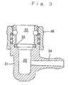
- a dialyzer connecting coupler which connects a solution transferring line such as a dialysis solution circulating hose to a connection coupler of a dialyzer is shown in Fig. 3 by way of example.
- a fitting portion 32 into which a connection plug is to be removably fitted and a cavity portion 33 for communicating with the inside of the connection plug are formed in the inside of a body 31, and a tube-shaped, hose connecting portion 34 is formed integrally with the body 31 in a laterally projecting shape, and its inside communicates with the cavity portion 33.
- an O-ring 35 for liquid-tightly connecting the connection plug and the fitting portion 32 is provided in the body 31, and the body 31 is provided with a fixing mechanism 36 which releasably fixes the connection plug to the body 31.
- the connecting coupler shown in Fig. 3 is used as a connecting coupler which is connected to a connection plug of a dialyzer, as mentioned above, there is a risk that bacteria are generated in the connecting coupler and endotoxin separates from the bacteria and enters into the dialysis solution.
- the main cause of this risk is that when the connection plug and the connecting coupler are connected to each other, a dead space (gap) is formed in a portion surrounding the O-ring 35 and the dialysis solution stays in this portion and, after the completion of dialysis, the portion surrounding the O-ring 35 is difficult to clean.
- the invention is characterized by including:
- the fixing mechanism may be formed of a metal material.
- a dialyzer connecting coupler 1 has a body 2, a line connector 3, a coupling tube 4, a fixing mechanism 5, and the like.
- the body 2 is integrally formed, and a tip portion 7 is made smaller in diameter than a base portion 8 and an L-shaped solution transferring passage 9 is formed in the inside.
- One end portion of the solution transferring passage 9 has a plug-receiving opening portion 10 which is opened in a tip surface of the body 2, and a connection plug 11 of a dialyzer (not shown) is removably relatively fitted into the opening portion 10.
- the plug-receiving opening portion 10 is made larger in diameter than the portion of the solution transferring passage 9 that neighbors the plug-receiving opening portion 10, and the inside bottom of the plug-receiving opening portion 10 forms a first seal surface 12, and the side surface of the plug-receiving opening portion 10 forms a second seal surface 13.
- the second seal surface 13 assumes the state shown in Fig. 2, whereas when the connection plug 11 is connected, the second seal surface 13, as shown in Fig. 1, abuts with the connection plug 11 and the whole (or approximately the whole, an essential portion, or a part) of the second seal surface 13 is elastically deformed diametrically outwardly and establishes liquid-tight contact with the side surface of the tip portion of the connection plug 11.
- the other end portion of the solution transferring passage 9 forms a line-receiving opening portion 14 which is opened on one side.
- the line-receiving opening portion 14 may also be opened on another side such as the base end face of the body 2.
- the body 2 is formed of an elastic material (i.e., a rubber-like elastic material or a rubber-like elastomer).
- an elastic material i.e., a rubber-like elastic material or a rubber-like elastomer.
- a material is used which is low in elastic modulus and is large in elastic limit and which does not physically nor chemically react with dialysis solutions (namely, is inactive against dialysis solutions) and can prevent penetration of microorganisms.
- silicone rubber and various other elastomers are preferred.
- the line connector 3 is integrally formed in a tubular shape, and its base portion is fixedly inserted in a side portion of the base portion 8 of the body 2 and its interior communicates with the line-receiving opening portion 14.
- the mounting of the line connector 3 on the body may be effected by insert-molding, or the line connector 3 may be inserted into the body 2 and fixed thereto with an adhesive.
- a solution transferring line (not shown) such as a dialysis solution circulating hose is separably fitted onto and connected to the tip portion of the line connector 3.
- the line connector 3 is formed of a metal material or a synthetic resin material.
- this metal material a material is used which does not physically nor chemically react with dialysis solutions (namely, is inactive against dialysis solutions) and can prevent penetration of microorganisms.
- stainless steel is preferred.
- synthetic resin synthetic resins for medical use can be used.
- the coupling tube 4 is integrally formed in a cylindrical shape, and has a fixing portion 16 and a coupling portion 17.
- the fixing portion 16 is fixedly fitted on the tip portion 7 of the body 2.
- the mounting of the coupling tube 4 on the body 2 may be effected by insert-molding, or the fixing portion 16 may be fitted onto the body 2 and fixed thereto with an adhesive.
- the coupling portion 17 is adapted to be removably fitted onto the portion of the connection plug 11 that excludes the tip portion thereof, and projects from the fixing portion 16 toward the front in the axial direction.
- the outside and inside diameters of the coupling portion 17 are made smaller than those of the fixing portion 16, and a stepped surface 19 which has a planar shape facing toward the base portion of the body 2 is formed on an inside surface of the boundary portion between the fixing portion 16 and the coupling portion 17, and this stepped surface 19 is in close contact with the entire tip surface of the body 2.
- a stepped surface 20 which has a planar shape facing toward the base portion of the body 2 is formed on an outside surface of the boundary portion between the fixing portion 16 and the coupling portion 17.
- the inside surface of the coupling portion 17 is made flush with and contiguous with the second seal surface 13, and a plurality of ball holes 21 each having a tapered shape extending through the coupling portion 17 in a radial direction thereof are formed in a portion of the coupling portion 17 that is near the tip thereof, in such a manner as to be circumferentially spaced apart from one another at equal intervals.
- the coupling tube 4 is formed of a metal material or a synthetic resin material. As the metal material, a material similar to that of the line connector 3 is used.
- the fixing mechanism 5 releasably fixes the coupling tube 4 to the connection plug 11 in a state of the body 2 pressing against the connection plug 11, and includes a plurality of balls 23, a coil spring 24, first and second ring-shaped stoppers 25 and 26, a sleeve 27 and the like.
- Each of the members of the fixing mechanism 5 is formed of a metal material or a synthetic resin material. As the metal material, a material similar to that of the line connector 3 is used.
- each of the balls 23 is positionally changeable between an engagement position where the ball 23 projects into the inside of the coupling tube 4 and disengageably engages with a peripheral groove 29 of the connection plug 11 and an allowable position which is a position radially outward of the engagement position with respect to the radial direction of the coupling tube 4 and allows the connection plug 11 to be fitted into and removed from the coupling tube 4.
- the coil spring 24 is fitted on the coupling portion 17 of the coupling tube 4 and the balls 23.
- the first stopper 25 is fitted on the peripheral surface of the coupling portion 17 of the coupling tube 4 on the side of the balls 23 which is close to the tip of the coupling portion 17, and the second stopper 26 is fitted in the sleeve 27 on the side of the tip thereof and is positioned closer to the body 2 than is the first stopper 25.
- the coil spring 24 is resiliently inserted between the stepped surface 20 of the coupling tube 4 and the second stopper.
- the sleeve 27 is axially movably fitted on the coupling tube 4 and the coil spring 24, and is urged toward the front (upward in Fig. 1) in the axial direction by the coil spring 24.
- the sleeve 27, as shown in Fig. 1, is positionally changeable via the coil spring 24 between a fixing position for holding the balls 23 at the engagement position and a release position.
- the sleeve 27 is located on a side which is axially closer to the body 2 than when the sleeve 27 is at the holding position, and compresses the coil spring 24 toward the body 2 beyond the balls 23 in the axial direction to allow the balls 23 to move to the allowable position.
- the dialyzer connecting coupler 1 when not connected to the connection plug 11 of the dialyzer, is in the state shown in Fig. 2.
- a dialysis solution circulating hose is connected to the line connector 3 of the dialyzer connecting coupler 1, and as shown in Fig. 1, the dialyzer connecting coupler 1 is connected to the connection plug 11 of the dialyzer.
- connection plug 11 is fitted into the coupling portion 17 of the coupling tube 4 and the plug-receiving opening portion 10 of the body 2.
- the connection plug 11 can be fitted into the plug-receiving opening portion 10 without any difficulty.
- the tip portion of the connection plug 11 is relatively fitted into the plug-receiving opening portion 10 of the body 2 and the first seal surface 12 which is the bottom surface of the plug-receiving opening portion 10 is relatively pressed by the tip face of the connection plug 11, whereby the first seal surface 12 is elastically deformed toward the base portion 8 of the body 2 and establishes liquid-tight contact with the tip face of the connection plug 11.
- the second seal surface 13 which is the side surface of the plug-receiving opening portion 10 is relatively pressed by the side surface of the tip portion of the connection plug 11, whereby second seal surface 13 is elastically deformed radially outwardly and establishes liquid-tight contact with the side surface of the tip portion of the connection plug 11.
- the connecting coupler 1 is liquid-tightly connected to the connection plug 11 in a state of being pressed against the connecting plug 11, thereby causing the solution transferring passage 9 of the body 2 and the interior of the connection plug 11 to communicate with each other.
- the fixing mechanism 5 is returned to the fixing position shown in Fig. 1 by the coil spring 24, whereby the fixing mechanism 5 presses the balls 23 radially inwardly via the coil spring 24 and causes the balls 23 to move to the engagement position. Accordingly, the balls 23 disengageably engage with the peripheral groove 29 of the connection plug 11 so that the connecting coupler 1 and the connection plug 11 are fixed in the above-mentioned state.
- the fixing mechanism 5 is set to the release position and the connection plug 11 is relatively released from the connecting coupler 1, whereby the connection can be easily released.
- the first seal surface 12 which is the bottom surface of the plug-receiving opening portion 10 is elastically deformed toward the base portion 8 of the body 2 by the tip face of the connection plug 11, whereby the first seal surface 12 is brought into liquid-tight contact with the tip face of the connection plug 11.
- the second seal surface 13, which is the side surface of the plug-receiving opening portion 10 is elastically deformed radially outwardly by the side surface of the tip portion of the connection plug 11, whereby the second seal surface 13 is brought into liquid-tight contact with the side surface of the tip portion of the connection plug 11. Accordingly, the connecting coupler 1 can be positively liquid-tightly connected to the connection plug 11.
- the coupling tube 4 and the fixing mechanism 5 for fixing the connection plug 11, as well as the line connector 3 to which a solution transferring line such as a dialysis solution circulating hose is connected are not formed of an elastic material and are, therefore, large in strength. Accordingly, even if the connecting coupler 1 is used for a long term, there is no great risk that the coupling tube 4, the fixing mechanism 5 or the line connector 3 is deformed, nor a great risk that the connecting coupler 1 itself is deformed.
- a connecting coupler can be positively liquid-tightly connected to a connection plug, and there is no great risk that bacteria form in the connecting coupler, and there is also no great risk that a pyrogenic substance such as an endotoxin separated from bacteria enters into a dialysis solution.
- a connecting coupler is used for a long term, there is no great risk that a coupling tube, a line connector or the like is deformed, nor a great risk that the connecting coupler itself is deformed.
- the fixing mechanism is formed of a metal material, even if the connecting coupler is used for a long term, there is no great risk that the fixing mechanism is deformed, and the risk that the connecting coupler itself is deformed can be reduced to a further extent.
Landscapes
- Engineering & Computer Science (AREA)
- Health & Medical Sciences (AREA)
- Heart & Thoracic Surgery (AREA)
- General Engineering & Computer Science (AREA)
- Hematology (AREA)
- Pulmonology (AREA)
- Anesthesiology (AREA)
- Biomedical Technology (AREA)
- Mechanical Engineering (AREA)
- Life Sciences & Earth Sciences (AREA)
- Animal Behavior & Ethology (AREA)
- General Health & Medical Sciences (AREA)
- Public Health (AREA)
- Veterinary Medicine (AREA)
- External Artificial Organs (AREA)
- Quick-Acting Or Multi-Walled Pipe Joints (AREA)
Abstract
Description
- The present invention relates to a dialyzer connecting coupler for connecting a solution transferring line such as a dialysis solution circulating hose to a connection plug (a dialysis solution inlet or outlet) of a dialyzer.
- A dialyzer connecting coupler which connects a solution transferring line such as a dialysis solution circulating hose to a connection coupler of a dialyzer is shown in Fig. 3 by way of example. In this dialyzer, a
fitting portion 32 into which a connection plug is to be removably fitted and acavity portion 33 for communicating with the inside of the connection plug are formed in the inside of abody 31, and a tube-shaped,hose connecting portion 34 is formed integrally with thebody 31 in a laterally projecting shape, and its inside communicates with thecavity portion 33. In addition, an O-ring 35 for liquid-tightly connecting the connection plug and thefitting portion 32 is provided in thebody 31, and thebody 31 is provided with afixing mechanism 36 which releasably fixes the connection plug to thebody 31. - In recent years, in view of greater improvements in substance permeation performance of dialyzers due to higher performance thereof, more attention has been drawn to the risk that a pyrogenic substance such as an endotoxin will enter into blood from a dialysis solution. From this possiblity, the necessity to purify dialysis solutions has increased, and various contrivances have been made. For example, during actual production of a dialysis solution, RO water (water processed by a reverse osmosis film) is used, and during dialysis, an endotoxin removing filter is disposed in front of the dialyzer.
- However, even if a dialysis solution is fully purified as mentioned above, in the case where the connecting coupler shown in Fig. 3 is used as a connecting coupler which is connected to a connection plug of a dialyzer, as mentioned above, there is a risk that bacteria are generated in the connecting coupler and endotoxin separates from the bacteria and enters into the dialysis solution. The main cause of this risk is that when the connection plug and the connecting coupler are connected to each other, a dead space (gap) is formed in a portion surrounding the O-
ring 35 and the dialysis solution stays in this portion and, after the completion of dialysis, the portion surrounding the O-ring 35 is difficult to clean. - It is an object of the present invention to provide a dialyzer connecting coupler capable of solving the above-mentioned problem, i.e. a dialyzer connecting coupler which minimizes the risk of bacteria entering into the dialysis solution.
- This object is achieved by a dialyzer connecting coupler according to claim 1. The dependent claim defines a preferred embodiment of the coupler.
- To achieve the above object, the invention is characterized by including:
- A) a body which is formed of an elastic material and has a solution transferring passage formed in its inside, the solution transferring passage having a plug-receiving opening portion opened at a tip portion thereof, a tip portion of a connection plug of a dialyzer being capable of being removably fitted into this plug-receiving opening portion;
- B) a line connector which is fitted into the body so that its inside communicates with the solution transferring passage, and to which a solution transferring line is connected;
- C) a coupling tube which is formed in a tubular shape and has a fixing portion fixedly fitted on the tip portion of the body and a coupling portion projecting from the fixing portion toward a front in an axial direction and removably fitted onto a portion of the connection plug that excludes the tip portion thereof; and
- D) a fixing mechanism which releasably fixes the coupling tube to the connection plug in the state of pressing the body against the connection plug, the plug-receiving opening portion being made larger in diameter than the portion of the solution transferring passage that neighbors the plug-receiving opening portion, an inside bottom of the plug-receiving opening portion forming a first seal surface which, when the connection plug is connected, is brought into abutment with the connection plug and is elastically deformed toward a base portion of the body to come into liquid-tight contact with a tip face of the connection plug, a side surface of the plug-receiving opening portion forming a second seal surface which is flush with and contiguous to an inside surface of the coupling portion of the coupling tube and, when the connection plug is connected, is brought into abutment with the connection plug and is elastically deformed diametrically outwardly to come into liquid-tight contact with the side surface of the tip portion of the connection plug.
-
- It is to be noted that the fixing mechanism may be formed of a metal material.
-
- [Fig. 1] A cross-sectional view showing the operating state of the connector of the invention.
- [Fig. 2] A cross-sectional view of one embodiment of the invention.
- [Fig. 3] A cross-sectional view showing a prior-art example.
-
- One embodiment of the invention is described below with reference to Figs. 1 and 2. A dialyzer connecting coupler 1 has a
body 2, aline connector 3, acoupling tube 4, afixing mechanism 5, and the like. - The
body 2 is integrally formed, and atip portion 7 is made smaller in diameter than abase portion 8 and an L-shapedsolution transferring passage 9 is formed in the inside. One end portion of thesolution transferring passage 9 has a plug-receivingopening portion 10 which is opened in a tip surface of thebody 2, and a connection plug 11 of a dialyzer (not shown) is removably relatively fitted into theopening portion 10. The plug-receivingopening portion 10 is made larger in diameter than the portion of thesolution transferring passage 9 that neighbors the plug-receivingopening portion 10, and the inside bottom of the plug-receivingopening portion 10 forms afirst seal surface 12, and the side surface of the plug-receivingopening portion 10 forms asecond seal surface 13. Thefirst seal surface 12, when the connection plug 11 is connected, abuts with the connection plug 11 (is pressed by the connection plug 11) and is elastically deformed toward thebase portion 8 of thebody 2 and establishes liquid-tight contact with the tip face of the connection plug 11. When the connection plug 11 is unconnected, thesecond seal surface 13 assumes the state shown in Fig. 2, whereas when the connection plug 11 is connected, thesecond seal surface 13, as shown in Fig. 1, abuts with the connection plug 11 and the whole (or approximately the whole, an essential portion, or a part) of thesecond seal surface 13 is elastically deformed diametrically outwardly and establishes liquid-tight contact with the side surface of the tip portion of the connection plug 11. The other end portion of thesolution transferring passage 9 forms a line-receivingopening portion 14 which is opened on one side. Incidentally, the line-receivingopening portion 14 may also be opened on another side such as the base end face of thebody 2. - The
body 2 is formed of an elastic material (i.e., a rubber-like elastic material or a rubber-like elastomer). As this elastic material, a material is used which is low in elastic modulus and is large in elastic limit and which does not physically nor chemically react with dialysis solutions (namely, is inactive against dialysis solutions) and can prevent penetration of microorganisms. Specifically, silicone rubber and various other elastomers are preferred. - The
line connector 3 is integrally formed in a tubular shape, and its base portion is fixedly inserted in a side portion of thebase portion 8 of thebody 2 and its interior communicates with the line-receivingopening portion 14. Incidentally, the mounting of theline connector 3 on the body may be effected by insert-molding, or theline connector 3 may be inserted into thebody 2 and fixed thereto with an adhesive. A solution transferring line (not shown) such as a dialysis solution circulating hose is separably fitted onto and connected to the tip portion of theline connector 3. Theline connector 3 is formed of a metal material or a synthetic resin material. As this metal material, a material is used which does not physically nor chemically react with dialysis solutions (namely, is inactive against dialysis solutions) and can prevent penetration of microorganisms. Specifically, stainless steel is preferred. As the synthetic resin, synthetic resins for medical use can be used. - The
coupling tube 4 is integrally formed in a cylindrical shape, and has afixing portion 16 and acoupling portion 17. Thefixing portion 16 is fixedly fitted on thetip portion 7 of thebody 2. Incidentally, the mounting of thecoupling tube 4 on thebody 2 may be effected by insert-molding, or thefixing portion 16 may be fitted onto thebody 2 and fixed thereto with an adhesive. Thecoupling portion 17 is adapted to be removably fitted onto the portion of the connection plug 11 that excludes the tip portion thereof, and projects from thefixing portion 16 toward the front in the axial direction. The outside and inside diameters of thecoupling portion 17 are made smaller than those of thefixing portion 16, and astepped surface 19 which has a planar shape facing toward the base portion of thebody 2 is formed on an inside surface of the boundary portion between thefixing portion 16 and thecoupling portion 17, and this steppedsurface 19 is in close contact with the entire tip surface of thebody 2. Astepped surface 20 which has a planar shape facing toward the base portion of thebody 2 is formed on an outside surface of the boundary portion between thefixing portion 16 and thecoupling portion 17. In addition, the inside surface of thecoupling portion 17 is made flush with and contiguous with thesecond seal surface 13, and a plurality ofball holes 21 each having a tapered shape extending through thecoupling portion 17 in a radial direction thereof are formed in a portion of thecoupling portion 17 that is near the tip thereof, in such a manner as to be circumferentially spaced apart from one another at equal intervals. Thecoupling tube 4 is formed of a metal material or a synthetic resin material. As the metal material, a material similar to that of theline connector 3 is used. - The
fixing mechanism 5 releasably fixes thecoupling tube 4 to the connection plug 11 in a state of thebody 2 pressing against the connection plug 11, and includes a plurality ofballs 23, acoil spring 24, first and second ring-shaped stoppers sleeve 27 and the like. Each of the members of thefixing mechanism 5 is formed of a metal material or a synthetic resin material. As the metal material, a material similar to that of theline connector 3 is used. - The
balls 23 are provided in therespective ball holes 21 of thecoupling tube 4 so that therespective balls 23 can move in a radial direction of thecoupling tube 4. As shown in Fig. 1, each of theballs 23 is positionally changeable between an engagement position where theball 23 projects into the inside of thecoupling tube 4 and disengageably engages with aperipheral groove 29 of the connection plug 11 and an allowable position which is a position radially outward of the engagement position with respect to the radial direction of thecoupling tube 4 and allows the connection plug 11 to be fitted into and removed from thecoupling tube 4. - The
coil spring 24 is fitted on thecoupling portion 17 of thecoupling tube 4 and theballs 23. - The
first stopper 25 is fitted on the peripheral surface of thecoupling portion 17 of thecoupling tube 4 on the side of theballs 23 which is close to the tip of thecoupling portion 17, and thesecond stopper 26 is fitted in thesleeve 27 on the side of the tip thereof and is positioned closer to thebody 2 than is thefirst stopper 25. Thecoil spring 24 is resiliently inserted between thestepped surface 20 of thecoupling tube 4 and the second stopper. - The
sleeve 27 is axially movably fitted on thecoupling tube 4 and thecoil spring 24, and is urged toward the front (upward in Fig. 1) in the axial direction by thecoil spring 24. Thesleeve 27, as shown in Fig. 1, is positionally changeable via thecoil spring 24 between a fixing position for holding theballs 23 at the engagement position and a release position. When thesleeve 27 is at the release position, thesleeve 27 is located on a side which is axially closer to thebody 2 than when thesleeve 27 is at the holding position, and compresses thecoil spring 24 toward thebody 2 beyond theballs 23 in the axial direction to allow theballs 23 to move to the allowable position. - According to the above-described construction example, the dialyzer connecting coupler 1, when not connected to the connection plug 11 of the dialyzer, is in the state shown in Fig. 2. During dialysis, a dialysis solution circulating hose is connected to the
line connector 3 of the dialyzer connecting coupler 1, and as shown in Fig. 1, the dialyzer connecting coupler 1 is connected to the connection plug 11 of the dialyzer. - At the time of dialysis, the
sleeve 27 of thefixing mechanism 5 is pressed against thecoil spring 24 toward thebody 2 and is set to the release position, and in this state, the connection plug 11 is fitted into thecoupling portion 17 of thecoupling tube 4 and the plug-receivingopening portion 10 of thebody 2. At this time, since theballs 23 move to the allowable position, the connection plug 11 can be fitted into the plug-receivingopening portion 10 without any difficulty. - In the above-described manner, the tip portion of the connection plug 11 is relatively fitted into the plug-receiving
opening portion 10 of thebody 2 and thefirst seal surface 12 which is the bottom surface of the plug-receivingopening portion 10 is relatively pressed by the tip face of the connection plug 11, whereby thefirst seal surface 12 is elastically deformed toward thebase portion 8 of thebody 2 and establishes liquid-tight contact with the tip face of the connection plug 11. In addition, thesecond seal surface 13 which is the side surface of the plug-receivingopening portion 10 is relatively pressed by the side surface of the tip portion of the connection plug 11, wherebysecond seal surface 13 is elastically deformed radially outwardly and establishes liquid-tight contact with the side surface of the tip portion of the connection plug 11. In this manner, the connecting coupler 1 is liquid-tightly connected to the connection plug 11 in a state of being pressed against the connecting plug 11, thereby causing thesolution transferring passage 9 of thebody 2 and the interior of the connection plug 11 to communicate with each other. - Subsequently, when the pressure of the
fixing mechanism 5 is released, thefixing mechanism 5 is returned to the fixing position shown in Fig. 1 by thecoil spring 24, whereby thefixing mechanism 5 presses theballs 23 radially inwardly via thecoil spring 24 and causes theballs 23 to move to the engagement position. Accordingly, theballs 23 disengageably engage with theperipheral groove 29 of the connection plug 11 so that the connecting coupler 1 and the connection plug 11 are fixed in the above-mentioned state. - Incidentally, when the connection between the connecting coupler 1 and the connection plug 11 is to be released, the
fixing mechanism 5 is set to the release position and the connection plug 11 is relatively released from the connecting coupler 1, whereby the connection can be easily released. - According to the above-described construction example, the
first seal surface 12 which is the bottom surface of the plug-receivingopening portion 10 is elastically deformed toward thebase portion 8 of thebody 2 by the tip face of the connection plug 11, whereby thefirst seal surface 12 is brought into liquid-tight contact with the tip face of the connection plug 11. In addition, thesecond seal surface 13, which is the side surface of the plug-receivingopening portion 10, is elastically deformed radially outwardly by the side surface of the tip portion of the connection plug 11, whereby thesecond seal surface 13 is brought into liquid-tight contact with the side surface of the tip portion of the connection plug 11. Accordingly, the connecting coupler 1 can be positively liquid-tightly connected to the connection plug 11. - In addition, since an O-ring or the like is not used, unlike the prior art, there is no problem that a dead space (gap) in which a dialysis solution stays is formed in a portion surrounding the O-ring, like the prior art. In addition, since the inside surface of the
coupling portion 17 of thecoupling tube 4 is made flush with and contiguous to thesecond seal surface 13, after the completion of dialysis, it is possible to easily perform cleaning of the portion of the inside surface of thecoupling portion 17 or the like that is adjacent to the plug-receivingopening portion 10, not to mention the plug-receivingopening portion 10 of thebody 2. Accordingly, there is no great risk that bacteria form in the connecting coupler 1, and there is also no great risk that a pyrogenic substance such as an endotoxin separated from bacteria enters into a dialysis solution. - In addition, in the connecting coupler 1, the
coupling tube 4 and thefixing mechanism 5 for fixing the connection plug 11, as well as theline connector 3 to which a solution transferring line such as a dialysis solution circulating hose is connected, are not formed of an elastic material and are, therefore, large in strength. Accordingly, even if the connecting coupler 1 is used for a long term, there is no great risk that thecoupling tube 4, thefixing mechanism 5 or theline connector 3 is deformed, nor a great risk that the connecting coupler 1 itself is deformed. - As described hereinabove in detail, according to the invention, a connecting coupler can be positively liquid-tightly connected to a connection plug, and there is no great risk that bacteria form in the connecting coupler, and there is also no great risk that a pyrogenic substance such as an endotoxin separated from bacteria enters into a dialysis solution. In addition, even if the connecting coupler is used for a long term, there is no great risk that a coupling tube, a line connector or the like is deformed, nor a great risk that the connecting coupler itself is deformed.
- In addition, according to the invention wherein the fixing mechanism is formed of a metal material, even if the connecting coupler is used for a long term, there is no great risk that the fixing mechanism is deformed, and the risk that the connecting coupler itself is deformed can be reduced to a further extent.
Claims (2)
- A dialyzer connecting coupler (1) for connecting with a connection plug (11) of a dialyzer, comprising:the plug-receiving opening portion (10) being made larger in diameter than the portion of the solution transferring passage (9) that neighbors the plug-receiving opening portion (10),A) a body (2) which is formed of an elastic material and has a solution transferring passage (9) formed in its inside, the solution transferring passage (9) having a plug-receiving opening portion (10) opened at a tip portion (7) of the solution transferring passage (9), a tip portion of the connection plug (11) being adapted to be removably fitted into the plug-receiving opening portion (10);B) a line connector (3) which is fitted into the body (2) so that its inside communicates with the solution transferring passage (9), and to which a solution transferring line can be connected;C) a coupling tube (4) which is formed in a tubular shape and has a fixing portion (16) fixedly fitted on the tip portion (7) of the body (2) and a coupling portion (17) projected from the fixing portion (16) in an axial direction and that is adapted to be removably fitted onto a portion of the connection plug (11) that excludes the tip portion of the plug (11); andD) a fixing mechanism (5) which releasably fixes the coupling tube (4) to the connection plug (11) in a state of pressing the body (2) against the connection plug (11),
an inside bottom of the plug-receiving opening portion forming a first seal surface (12) which, when the connection plug (11) is connected, is brought into abutment with the connection plug (11) and is elastically deformed toward a base portion (8) of the body (2) to liquid-tightly contact with a tip face of the connection plug (11),
a side surface of the plug-receiving opening portion (10) forming a second seal surface (13) which is made flush with and contiguous to an inside surface of the coupling portion (17) of the coupling tube (4) and, when the connection plug (11) is connected, is brought into abutment with the connection plug (11) and is elastically deformed diametrically outwardly to liquid-tightly contact with the side surface of the tip portion of the connection plug (11). - The dialyzer connecting coupler according to claim 1, wherein the fixing mechanism (5) is formed of a metal material.
Applications Claiming Priority (2)
| Application Number | Priority Date | Filing Date | Title |
|---|---|---|---|
| JP2003174029A JP4286073B2 (en) | 2003-06-18 | 2003-06-18 | Coupler for dialyzer connection |
| JP2003174029 | 2003-06-18 |
Publications (2)
| Publication Number | Publication Date |
|---|---|
| EP1488825A1 true EP1488825A1 (en) | 2004-12-22 |
| EP1488825B1 EP1488825B1 (en) | 2008-11-12 |
Family
ID=33410965
Family Applications (1)
| Application Number | Title | Priority Date | Filing Date |
|---|---|---|---|
| EP04014045A Expired - Lifetime EP1488825B1 (en) | 2003-06-18 | 2004-06-16 | Dialyzer connecting coupler |
Country Status (5)
| Country | Link |
|---|---|
| US (1) | US7017948B2 (en) |
| EP (1) | EP1488825B1 (en) |
| JP (1) | JP4286073B2 (en) |
| AT (1) | ATE413900T1 (en) |
| DE (1) | DE602004017670D1 (en) |
Cited By (2)
| Publication number | Priority date | Publication date | Assignee | Title |
|---|---|---|---|---|
| CN104208765A (en) * | 2014-08-15 | 2014-12-17 | 袁毅强 | Connector sterilization combination for haemodialysis machine |
| DE102022101299A1 (en) | 2022-01-20 | 2023-07-20 | B.Braun Avitum Ag | Extracorporeal blood treatment machine with operating device |
Families Citing this family (32)
| Publication number | Priority date | Publication date | Assignee | Title |
|---|---|---|---|---|
| DE10352859B3 (en) * | 2003-11-10 | 2005-06-02 | Fresenius Medical Care Deutschland Gmbh | Connector for dialyzer port |
| DK176145B1 (en) * | 2004-09-23 | 2006-10-02 | Guldmann V As | Clutch |
| US10537671B2 (en) | 2006-04-14 | 2020-01-21 | Deka Products Limited Partnership | Automated control mechanisms in a hemodialysis apparatus |
| US7794141B2 (en) | 2006-04-14 | 2010-09-14 | Deka Products Limited Partnership | Thermal and coductivity sensing systems, devices and methods |
| US8425471B2 (en) | 2007-02-27 | 2013-04-23 | Deka Products Limited Partnership | Reagent supply for a hemodialysis system |
| US8409441B2 (en) | 2007-02-27 | 2013-04-02 | Deka Products Limited Partnership | Blood treatment systems and methods |
| US8366655B2 (en) | 2007-02-27 | 2013-02-05 | Deka Products Limited Partnership | Peritoneal dialysis sensor apparatus systems, devices and methods |
| CA2681912C (en) | 2007-02-27 | 2015-09-29 | Deka Products Limited Partnership | Hemodialysis systems and methods |
| US8042563B2 (en) | 2007-02-27 | 2011-10-25 | Deka Products Limited Partnership | Cassette system integrated apparatus |
| US8491184B2 (en) | 2007-02-27 | 2013-07-23 | Deka Products Limited Partnership | Sensor apparatus systems, devices and methods |
| US8393690B2 (en) | 2007-02-27 | 2013-03-12 | Deka Products Limited Partnership | Enclosure for a portable hemodialysis system |
| US9028691B2 (en) | 2007-02-27 | 2015-05-12 | Deka Products Limited Partnership | Blood circuit assembly for a hemodialysis system |
| US8357298B2 (en) | 2007-02-27 | 2013-01-22 | Deka Products Limited Partnership | Hemodialysis systems and methods |
| US8562834B2 (en) | 2007-02-27 | 2013-10-22 | Deka Products Limited Partnership | Modular assembly for a portable hemodialysis system |
| US20090107335A1 (en) | 2007-02-27 | 2009-04-30 | Deka Products Limited Partnership | Air trap for a medical infusion device |
| US8771508B2 (en) * | 2008-08-27 | 2014-07-08 | Deka Products Limited Partnership | Dialyzer cartridge mounting arrangement for a hemodialysis system |
| US11833281B2 (en) | 2008-01-23 | 2023-12-05 | Deka Products Limited Partnership | Pump cassette and methods for use in medical treatment system using a plurality of fluid lines |
| US11738130B2 (en) | 2008-01-23 | 2023-08-29 | Deka Products Limited Partnership | Fluid line autoconnect apparatus and methods for medical treatment system |
| WO2010009395A1 (en) * | 2008-07-18 | 2010-01-21 | Clark Equipment Company | Integral 90 degree fitting hydraulic quick coupler and attachments and work machines employing the same |
| EP3072545B1 (en) | 2009-10-30 | 2019-05-08 | DEKA Products Limited Partnership | Apparatus for detecting disconnection of an intravascular access device |
| US8505955B2 (en) * | 2010-02-11 | 2013-08-13 | Remark Technologies, Inc. | Coupling device and method |
| EP4249964B1 (en) | 2010-07-07 | 2025-10-15 | DEKA Products Limited Partnership | Medical treatment system and methods using a plurality of fluid lines |
| SG195155A1 (en) | 2011-05-24 | 2013-12-30 | Deka Products Lp | Blood treatment systems and methods |
| AU2012258687C1 (en) | 2011-05-24 | 2018-03-08 | Deka Products Limited Partnership | Hemodial ysis system |
| HK1199851A1 (en) | 2011-09-21 | 2015-07-24 | Bayer Healthcare Llc | Continuous multi-fluid pump device, drive and actuating system and method |
| US20130136532A1 (en) * | 2011-11-28 | 2013-05-30 | Tsun-Chi Liao | Cymbal quick-release structure |
| EP2827039A1 (en) * | 2013-07-17 | 2015-01-21 | Volvo Car Corporation | Quick connector |
| RU2714926C2 (en) | 2015-01-09 | 2020-02-21 | БАЙЕР ХелсКер ЛЛСи | Multiple fluid delivery system with multi-use disposable set and features thereof |
| EP3386561B1 (en) | 2015-12-11 | 2023-05-03 | NxStage Medical, Inc. | Fluid line connector devices methods and systems |
| JP6393725B2 (en) * | 2016-10-25 | 2018-09-19 | 日機装株式会社 | Blood purification device and coupler |
| FR3061258B1 (en) * | 2016-12-23 | 2019-05-31 | Staubli Faverges | FEMALE CONNECTING ELEMENT, TO BE FITTED WITH AN ADDITIONAL MALE ELEMENT AND CONNECTION COMPRISING SUCH A FEMALE ELEMENT |
| US11333282B2 (en) | 2019-11-05 | 2022-05-17 | Diality Inc. | Locking connector |
Citations (3)
| Publication number | Priority date | Publication date | Assignee | Title |
|---|---|---|---|---|
| DE8519806U1 (en) * | 1985-07-09 | 1985-08-14 | B. Braun Melsungen Ag, 3508 Melsungen | Connection device |
| JP2758148B2 (en) * | 1995-08-14 | 1998-05-28 | 日機装株式会社 | Blood purifier coupler |
| JP2000014772A (en) * | 1998-06-29 | 2000-01-18 | Meteku:Kk | Sterilized connecting socket for dialyzer |
Family Cites Families (11)
| Publication number | Priority date | Publication date | Assignee | Title |
|---|---|---|---|---|
| US2518542A (en) * | 1948-07-21 | 1950-08-15 | Fred E Hansen | Steam hose coupling |
| US2631872A (en) * | 1949-01-24 | 1953-03-17 | Franklin T Wurmser | Quick coupling |
| US3334860A (en) * | 1964-07-13 | 1967-08-08 | Jr Cecil G Bolton | Fluid coupling |
| US4496458A (en) * | 1977-05-23 | 1985-01-29 | Extracorporeal Medical Specialties, Inc. | Dialysis apparatus and technique |
| US4198080A (en) * | 1978-05-19 | 1980-04-15 | Baxter Travenol Laboratories, Inc. | Telescoping-type connector |
| US5052725A (en) * | 1989-03-13 | 1991-10-01 | Colder Products Company | Two piece molded female coupling |
| BR9600812A (en) * | 1996-02-26 | 1997-12-23 | Tampas Click Ltda | Quick connector |
| JPH1170163A (en) * | 1997-06-18 | 1999-03-16 | Kawasumi Lab Inc | Coupler connector for hemodialyzer |
| DE60011359T2 (en) * | 1999-09-27 | 2005-06-16 | Legris S.A. | Device for connecting a line end to a connection part |
| JP3235064B2 (en) * | 2000-02-16 | 2001-12-04 | 株式会社メテク | Sterile coupler for dialyzer connection |
| EP1488826A1 (en) * | 2003-06-19 | 2004-12-22 | Nipro Corporation | Dialyzer-connecting coupler joint |
-
2003
- 2003-06-18 JP JP2003174029A patent/JP4286073B2/en not_active Expired - Lifetime
-
2004
- 2004-06-16 AT AT04014045T patent/ATE413900T1/en not_active IP Right Cessation
- 2004-06-16 EP EP04014045A patent/EP1488825B1/en not_active Expired - Lifetime
- 2004-06-16 DE DE602004017670T patent/DE602004017670D1/en not_active Expired - Lifetime
- 2004-06-17 US US10/869,043 patent/US7017948B2/en not_active Expired - Fee Related
Patent Citations (3)
| Publication number | Priority date | Publication date | Assignee | Title |
|---|---|---|---|---|
| DE8519806U1 (en) * | 1985-07-09 | 1985-08-14 | B. Braun Melsungen Ag, 3508 Melsungen | Connection device |
| JP2758148B2 (en) * | 1995-08-14 | 1998-05-28 | 日機装株式会社 | Blood purifier coupler |
| JP2000014772A (en) * | 1998-06-29 | 2000-01-18 | Meteku:Kk | Sterilized connecting socket for dialyzer |
Non-Patent Citations (2)
| Title |
|---|
| PATENT ABSTRACTS OF JAPAN vol. 1997, no. 06 30 June 1997 (1997-06-30) * |
| PATENT ABSTRACTS OF JAPAN vol. 2000, no. 04 31 August 2000 (2000-08-31) * |
Cited By (2)
| Publication number | Priority date | Publication date | Assignee | Title |
|---|---|---|---|---|
| CN104208765A (en) * | 2014-08-15 | 2014-12-17 | 袁毅强 | Connector sterilization combination for haemodialysis machine |
| DE102022101299A1 (en) | 2022-01-20 | 2023-07-20 | B.Braun Avitum Ag | Extracorporeal blood treatment machine with operating device |
Also Published As
| Publication number | Publication date |
|---|---|
| ATE413900T1 (en) | 2008-11-15 |
| JP2005006860A (en) | 2005-01-13 |
| US7017948B2 (en) | 2006-03-28 |
| US20040262917A1 (en) | 2004-12-30 |
| EP1488825B1 (en) | 2008-11-12 |
| JP4286073B2 (en) | 2009-06-24 |
| DE602004017670D1 (en) | 2008-12-24 |
Similar Documents
| Publication | Publication Date | Title |
|---|---|---|
| US7017948B2 (en) | Dialyzer connecting coupler | |
| JP6162199B2 (en) | A set of easy-to-clean connectors for liquid circuits | |
| JP3760251B2 (en) | Quick connector fitting with open mechanism that functions as one piece | |
| CN101658710B (en) | Plug-in connector for medical tubes | |
| US7857793B2 (en) | Luer cleaner | |
| US8425489B2 (en) | Drainage tube device and coupling unit | |
| US6170882B1 (en) | Coupling for waste water outlets | |
| CN1083959C (en) | Connection verifier for quick Connector coupling | |
| JPWO2014115566A1 (en) | Tube connection structure | |
| RU98114505A (en) | HOSE CONNECTION | |
| EP1649890A4 (en) | Connector system for medical use | |
| US10279158B2 (en) | Disposable connector for hemofiltration | |
| KR20220070317A (en) | Quick connections made of plastic | |
| KR20220070318A (en) | quick connection | |
| US6971680B2 (en) | Dialysis coupler assembly with joint members and hemodialysis system using same | |
| JP2007105543A (en) | Coupler for dialyzer connection | |
| EP1039206A3 (en) | Hose connector | |
| CN102697441A (en) | Stopper and endoscope | |
| EP1488826A1 (en) | Dialyzer-connecting coupler joint | |
| JP4356534B2 (en) | Coupler joint for dialyzer connection | |
| JPS6240562Y2 (en) | ||
| JP2003021280A (en) | Joint packing and pipe connection structure using the same | |
| JP6435621B2 (en) | Connector | |
| JP3887816B2 (en) | A pair of interconnectable couplers | |
| CN213248910U (en) | Auxiliary assembly device and assembly structure for endoscope perfusion apparatus |
Legal Events
| Date | Code | Title | Description |
|---|---|---|---|
| PUAI | Public reference made under article 153(3) epc to a published international application that has entered the european phase |
Free format text: ORIGINAL CODE: 0009012 |
|
| AK | Designated contracting states |
Kind code of ref document: A1 Designated state(s): AT BE BG CH CY CZ DE DK EE ES FI FR GB GR HU IE IT LI LU MC NL PL PT RO SE SI SK TR |
|
| AX | Request for extension of the european patent |
Extension state: AL HR LT LV MK |
|
| 17P | Request for examination filed |
Effective date: 20050523 |
|
| RIN1 | Information on inventor provided before grant (corrected) |
Inventor name: MASUDA, TOSHIAKI Inventor name: MORITA, YASUHIKO Inventor name: SUNOHARA, TAKASHI |
|
| AKX | Designation fees paid |
Designated state(s): AT BE BG CH CY CZ DE DK EE ES FI FR GB GR HU IE IT LI LU MC NL PL PT RO SE SI SK TR |
|
| GRAP | Despatch of communication of intention to grant a patent |
Free format text: ORIGINAL CODE: EPIDOSNIGR1 |
|
| GRAS | Grant fee paid |
Free format text: ORIGINAL CODE: EPIDOSNIGR3 |
|
| GRAA | (expected) grant |
Free format text: ORIGINAL CODE: 0009210 |
|
| AK | Designated contracting states |
Kind code of ref document: B1 Designated state(s): AT BE BG CH CY CZ DE DK EE ES FI FR GB GR HU IE IT LI LU MC NL PL PT RO SE SI SK TR |
|
| REG | Reference to a national code |
Ref country code: GB Ref legal event code: FG4D |
|
| REG | Reference to a national code |
Ref country code: CH Ref legal event code: EP |
|
| REG | Reference to a national code |
Ref country code: IE Ref legal event code: FG4D |
|
| REF | Corresponds to: |
Ref document number: 602004017670 Country of ref document: DE Date of ref document: 20081224 Kind code of ref document: P |
|
| PG25 | Lapsed in a contracting state [announced via postgrant information from national office to epo] |
Ref country code: AT Free format text: LAPSE BECAUSE OF FAILURE TO SUBMIT A TRANSLATION OF THE DESCRIPTION OR TO PAY THE FEE WITHIN THE PRESCRIBED TIME-LIMIT Effective date: 20081112 Ref country code: ES Free format text: LAPSE BECAUSE OF FAILURE TO SUBMIT A TRANSLATION OF THE DESCRIPTION OR TO PAY THE FEE WITHIN THE PRESCRIBED TIME-LIMIT Effective date: 20090223 |
|
| NLV1 | Nl: lapsed or annulled due to failure to fulfill the requirements of art. 29p and 29m of the patents act | ||
| PG25 | Lapsed in a contracting state [announced via postgrant information from national office to epo] |
Ref country code: SI Free format text: LAPSE BECAUSE OF FAILURE TO SUBMIT A TRANSLATION OF THE DESCRIPTION OR TO PAY THE FEE WITHIN THE PRESCRIBED TIME-LIMIT Effective date: 20081112 Ref country code: PL Free format text: LAPSE BECAUSE OF FAILURE TO SUBMIT A TRANSLATION OF THE DESCRIPTION OR TO PAY THE FEE WITHIN THE PRESCRIBED TIME-LIMIT Effective date: 20081112 Ref country code: NL Free format text: LAPSE BECAUSE OF FAILURE TO SUBMIT A TRANSLATION OF THE DESCRIPTION OR TO PAY THE FEE WITHIN THE PRESCRIBED TIME-LIMIT Effective date: 20081112 Ref country code: FI Free format text: LAPSE BECAUSE OF FAILURE TO SUBMIT A TRANSLATION OF THE DESCRIPTION OR TO PAY THE FEE WITHIN THE PRESCRIBED TIME-LIMIT Effective date: 20081112 |
|
| PG25 | Lapsed in a contracting state [announced via postgrant information from national office to epo] |
Ref country code: BG Free format text: LAPSE BECAUSE OF FAILURE TO SUBMIT A TRANSLATION OF THE DESCRIPTION OR TO PAY THE FEE WITHIN THE PRESCRIBED TIME-LIMIT Effective date: 20090212 Ref country code: BE Free format text: LAPSE BECAUSE OF FAILURE TO SUBMIT A TRANSLATION OF THE DESCRIPTION OR TO PAY THE FEE WITHIN THE PRESCRIBED TIME-LIMIT Effective date: 20081112 Ref country code: RO Free format text: LAPSE BECAUSE OF FAILURE TO SUBMIT A TRANSLATION OF THE DESCRIPTION OR TO PAY THE FEE WITHIN THE PRESCRIBED TIME-LIMIT Effective date: 20081112 Ref country code: DK Free format text: LAPSE BECAUSE OF FAILURE TO SUBMIT A TRANSLATION OF THE DESCRIPTION OR TO PAY THE FEE WITHIN THE PRESCRIBED TIME-LIMIT Effective date: 20081112 Ref country code: EE Free format text: LAPSE BECAUSE OF FAILURE TO SUBMIT A TRANSLATION OF THE DESCRIPTION OR TO PAY THE FEE WITHIN THE PRESCRIBED TIME-LIMIT Effective date: 20081112 |
|
| PG25 | Lapsed in a contracting state [announced via postgrant information from national office to epo] |
Ref country code: CZ Free format text: LAPSE BECAUSE OF FAILURE TO SUBMIT A TRANSLATION OF THE DESCRIPTION OR TO PAY THE FEE WITHIN THE PRESCRIBED TIME-LIMIT Effective date: 20081112 Ref country code: SE Free format text: LAPSE BECAUSE OF FAILURE TO SUBMIT A TRANSLATION OF THE DESCRIPTION OR TO PAY THE FEE WITHIN THE PRESCRIBED TIME-LIMIT Effective date: 20090212 Ref country code: PT Free format text: LAPSE BECAUSE OF FAILURE TO SUBMIT A TRANSLATION OF THE DESCRIPTION OR TO PAY THE FEE WITHIN THE PRESCRIBED TIME-LIMIT Effective date: 20090413 |
|
| PLBE | No opposition filed within time limit |
Free format text: ORIGINAL CODE: 0009261 |
|
| STAA | Information on the status of an ep patent application or granted ep patent |
Free format text: STATUS: NO OPPOSITION FILED WITHIN TIME LIMIT |
|
| PG25 | Lapsed in a contracting state [announced via postgrant information from national office to epo] |
Ref country code: SK Free format text: LAPSE BECAUSE OF FAILURE TO SUBMIT A TRANSLATION OF THE DESCRIPTION OR TO PAY THE FEE WITHIN THE PRESCRIBED TIME-LIMIT Effective date: 20081112 |
|
| 26N | No opposition filed |
Effective date: 20090813 |
|
| PG25 | Lapsed in a contracting state [announced via postgrant information from national office to epo] |
Ref country code: MC Free format text: LAPSE BECAUSE OF NON-PAYMENT OF DUE FEES Effective date: 20090630 |
|
| REG | Reference to a national code |
Ref country code: CH Ref legal event code: PL |
|
| REG | Reference to a national code |
Ref country code: IE Ref legal event code: MM4A |
|
| PG25 | Lapsed in a contracting state [announced via postgrant information from national office to epo] |
Ref country code: LI Free format text: LAPSE BECAUSE OF NON-PAYMENT OF DUE FEES Effective date: 20090630 Ref country code: CH Free format text: LAPSE BECAUSE OF NON-PAYMENT OF DUE FEES Effective date: 20090630 Ref country code: IE Free format text: LAPSE BECAUSE OF NON-PAYMENT OF DUE FEES Effective date: 20090616 |
|
| PG25 | Lapsed in a contracting state [announced via postgrant information from national office to epo] |
Ref country code: GR Free format text: LAPSE BECAUSE OF FAILURE TO SUBMIT A TRANSLATION OF THE DESCRIPTION OR TO PAY THE FEE WITHIN THE PRESCRIBED TIME-LIMIT Effective date: 20090213 |
|
| PG25 | Lapsed in a contracting state [announced via postgrant information from national office to epo] |
Ref country code: LU Free format text: LAPSE BECAUSE OF NON-PAYMENT OF DUE FEES Effective date: 20090616 |
|
| PG25 | Lapsed in a contracting state [announced via postgrant information from national office to epo] |
Ref country code: HU Free format text: LAPSE BECAUSE OF FAILURE TO SUBMIT A TRANSLATION OF THE DESCRIPTION OR TO PAY THE FEE WITHIN THE PRESCRIBED TIME-LIMIT Effective date: 20090513 |
|
| PG25 | Lapsed in a contracting state [announced via postgrant information from national office to epo] |
Ref country code: TR Free format text: LAPSE BECAUSE OF FAILURE TO SUBMIT A TRANSLATION OF THE DESCRIPTION OR TO PAY THE FEE WITHIN THE PRESCRIBED TIME-LIMIT Effective date: 20081112 |
|
| PG25 | Lapsed in a contracting state [announced via postgrant information from national office to epo] |
Ref country code: CY Free format text: LAPSE BECAUSE OF FAILURE TO SUBMIT A TRANSLATION OF THE DESCRIPTION OR TO PAY THE FEE WITHIN THE PRESCRIBED TIME-LIMIT Effective date: 20081112 |
|
| REG | Reference to a national code |
Ref country code: FR Ref legal event code: PLFP Year of fee payment: 13 |
|
| REG | Reference to a national code |
Ref country code: FR Ref legal event code: PLFP Year of fee payment: 14 |
|
| REG | Reference to a national code |
Ref country code: FR Ref legal event code: PLFP Year of fee payment: 15 |
|
| PGFP | Annual fee paid to national office [announced via postgrant information from national office to epo] |
Ref country code: IT Payment date: 20220627 Year of fee payment: 19 Ref country code: GB Payment date: 20220621 Year of fee payment: 19 |
|
| PGFP | Annual fee paid to national office [announced via postgrant information from national office to epo] |
Ref country code: FR Payment date: 20220628 Year of fee payment: 19 |
|
| PGFP | Annual fee paid to national office [announced via postgrant information from national office to epo] |
Ref country code: DE Payment date: 20220620 Year of fee payment: 19 |
|
| REG | Reference to a national code |
Ref country code: DE Ref legal event code: R119 Ref document number: 602004017670 Country of ref document: DE |
|
| GBPC | Gb: european patent ceased through non-payment of renewal fee |
Effective date: 20230616 |
|
| PG25 | Lapsed in a contracting state [announced via postgrant information from national office to epo] |
Ref country code: DE Free format text: LAPSE BECAUSE OF NON-PAYMENT OF DUE FEES Effective date: 20240103 Ref country code: GB Free format text: LAPSE BECAUSE OF NON-PAYMENT OF DUE FEES Effective date: 20230616 |
|
| PG25 | Lapsed in a contracting state [announced via postgrant information from national office to epo] |
Ref country code: FR Free format text: LAPSE BECAUSE OF NON-PAYMENT OF DUE FEES Effective date: 20230630 |
|
| PG25 | Lapsed in a contracting state [announced via postgrant information from national office to epo] |
Ref country code: IT Free format text: LAPSE BECAUSE OF NON-PAYMENT OF DUE FEES Effective date: 20230616 |