EP1488822A2 - Balloon catheter suited to kissing techniques - Google Patents
Balloon catheter suited to kissing techniques Download PDFInfo
- Publication number
- EP1488822A2 EP1488822A2 EP04014351A EP04014351A EP1488822A2 EP 1488822 A2 EP1488822 A2 EP 1488822A2 EP 04014351 A EP04014351 A EP 04014351A EP 04014351 A EP04014351 A EP 04014351A EP 1488822 A2 EP1488822 A2 EP 1488822A2
- Authority
- EP
- European Patent Office
- Prior art keywords
- balloon
- distal
- balloon catheter
- catheter according
- polyamide
- Prior art date
- Legal status (The legal status is an assumption and is not a legal conclusion. Google has not performed a legal analysis and makes no representation as to the accuracy of the status listed.)
- Granted
Links
- 0 **C(CCC1)C11C2(CCC2)CCCC1 Chemical compound **C(CCC1)C11C2(CCC2)CCCC1 0.000 description 1
Images



Classifications
-
- A—HUMAN NECESSITIES
- A61—MEDICAL OR VETERINARY SCIENCE; HYGIENE
- A61M—DEVICES FOR INTRODUCING MEDIA INTO, OR ONTO, THE BODY; DEVICES FOR TRANSDUCING BODY MEDIA OR FOR TAKING MEDIA FROM THE BODY; DEVICES FOR PRODUCING OR ENDING SLEEP OR STUPOR
- A61M25/00—Catheters; Hollow probes
- A61M25/10—Balloon catheters
- A61M25/1027—Making of balloon catheters
-
- A—HUMAN NECESSITIES
- A61—MEDICAL OR VETERINARY SCIENCE; HYGIENE
- A61L—METHODS OR APPARATUS FOR STERILISING MATERIALS OR OBJECTS IN GENERAL; DISINFECTION, STERILISATION OR DEODORISATION OF AIR; CHEMICAL ASPECTS OF BANDAGES, DRESSINGS, ABSORBENT PADS OR SURGICAL ARTICLES; MATERIALS FOR BANDAGES, DRESSINGS, ABSORBENT PADS OR SURGICAL ARTICLES
- A61L29/00—Materials for catheters, medical tubing, cannulae, or endoscopes or for coating catheters
- A61L29/08—Materials for coatings
- A61L29/085—Macromolecular materials
-
- A—HUMAN NECESSITIES
- A61—MEDICAL OR VETERINARY SCIENCE; HYGIENE
- A61L—METHODS OR APPARATUS FOR STERILISING MATERIALS OR OBJECTS IN GENERAL; DISINFECTION, STERILISATION OR DEODORISATION OF AIR; CHEMICAL ASPECTS OF BANDAGES, DRESSINGS, ABSORBENT PADS OR SURGICAL ARTICLES; MATERIALS FOR BANDAGES, DRESSINGS, ABSORBENT PADS OR SURGICAL ARTICLES
- A61L29/00—Materials for catheters, medical tubing, cannulae, or endoscopes or for coating catheters
- A61L29/14—Materials characterised by their function or physical properties, e.g. lubricating compositions
-
- A—HUMAN NECESSITIES
- A61—MEDICAL OR VETERINARY SCIENCE; HYGIENE
- A61M—DEVICES FOR INTRODUCING MEDIA INTO, OR ONTO, THE BODY; DEVICES FOR TRANSDUCING BODY MEDIA OR FOR TAKING MEDIA FROM THE BODY; DEVICES FOR PRODUCING OR ENDING SLEEP OR STUPOR
- A61M25/00—Catheters; Hollow probes
- A61M25/10—Balloon catheters
-
- A—HUMAN NECESSITIES
- A61—MEDICAL OR VETERINARY SCIENCE; HYGIENE
- A61M—DEVICES FOR INTRODUCING MEDIA INTO, OR ONTO, THE BODY; DEVICES FOR TRANSDUCING BODY MEDIA OR FOR TAKING MEDIA FROM THE BODY; DEVICES FOR PRODUCING OR ENDING SLEEP OR STUPOR
- A61M25/00—Catheters; Hollow probes
- A61M25/10—Balloon catheters
- A61M2025/1043—Balloon catheters with special features or adapted for special applications
- A61M2025/1088—Balloon catheters with special features or adapted for special applications having special surface characteristics depending on material properties or added substances, e.g. for reducing friction
Definitions
- the present invention relates to a balloon catheter.
- the balloon catheter according to the present invention is particularly suited to treatment of an area, such as a bifurcation of a blood vessel, which requires an operation of inserting two balloon catheters and expanding them in an objective area at the same time (also called a kissing technique).
- Balloon catheters have heretofore been used for treatment of stenoses due to thrombi formed in organic lumina of blood vessels, bile ducts, air tubes and other organs.
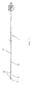
- a balloon catheter has a form approximately as shown in Fig. 1, and having a guide wire (GW) inserted through its internal cavity from a guide wire port 11, where the guide wire (GW) is inserted into, for example, a blood vessel.
- a balloon catheter (BC) is required to have an ability to cross to an objective area (cross ability), and therefore, is required to have an ability to be pushed into an objective area along the guide wire (GW) (pushability), followability which allows the balloon catheter (BC) to be easily deformed along the guide wire (GW), and a lubricative property of a portion to be inserted.
- a shaft 1 of the balloon catheter (BC) in general is flexible in a distal section 12 on a distal side relative to the guide wire port 11 and is stiff on a proximal side relative to the same.
- a lubricative property is imparted by lubrication processing to the distal section 12 on the distal side relative to the guide wire port 11, which section includes the balloon 3 and a distal portion 2 extending from the balloon straight portion toward the distal end.
- a method for lubricating processing in general, the formation of a lubricant film by silicone coating or hydrophilization processing with polyvinylpyrrolidone (PVP) or the like is adopted (US 5,503,631 and US 6,306,144).
- PVP polyvinylpyrrolidone
- Fig. 1 reference numeral 36 denotes a marker for confirming the position of the inserted balloon 3.
- the present invention has been made in view of the above-mentioned problem, and an object of the invention is to provide a balloon catheter which is improved in cross ability and is also improved in stability in an objective area (gripping property), which properties are adjusted with good balance so as not to cause slipping during kissing techniques.
- the invention relates to a balloon catheter suited to kissing techniques which includes a tubular body having a balloon provided on a flexible distal section of a stiff shaft and has a gripping property and a cross ability adjusted with good balance.
- cross ability usually refers to the ability of the catheter to successfully transmit pushing and guiding and steering forces applied at the proximal hub by the physician, such that the distal tip of the balloon catheter pushes into, through and past a constricted lesion.
- the term “gripping property” means the stability that the balloon catheter achieves in the objective area.
- the term “pushability” means a transmission of longitudinal forces along the guidewire from its proximal end to its distal end.
- followability means an easily deformable property of the balloon catheter along the guidewire.
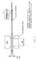
- the gripping property is expressed by a resistance value which is obtained when a balloon of length 20 mm and folding diameter 0.7 mm to 0.9 mm is fitted into a polyurethane tube (a polyether based aliphatic thermoplastic urethane under the trademark TELOCOFLEX EG-80A by Thermomedics, Inc.) having an inner diameter 2.4 mm and outer diameter of 4.0 mm and a length of 10 mm and the balloon is expanded to a diameter of 2.5 mm and pulled toward a proximal side at a speed of 250 mm/min in a water bath of 37°C, the resistance value being measured by a Universal Tensile Testing Instrument, ORIENTEC RTC-1225A (see, Fig. 6).
- a polyurethane tube a polyether based aliphatic thermoplastic urethane under the trademark TELOCOFLEX EG-80A by Thermomedics, Inc.
- the cross ability is expressed by a resistance value which is obtained when a balloon of length 20 mm and folding diameter 0.7 mm to 0.9 mm is pushed and inserted into a hole having a diameter of 0.4 mm in a polyurethane film (Esmer URS, Nippon Matai) having a thickness of 1 mm along with a guidewire at a speed of 500 mm/min in a water bath of 37°C, the resistance value being measured by a Universal Tensile Testing Instrument, ORIENTEC RTC-1225A (see, Fig.7).
- the gripping property is adjusted to 3.2 N to 6.0 N, and the cross ability is adjusted so that its initial value is not higher than 0. 65 N and its middle value is not higher than 0.40 N.
- the gripping property is 4.0 N to 6.0 N, and the cross ability is adjusted so that its initial value is not higher than 0.50 N and its middle value is not higher than 0.39 N.
- the initial value means the resistance value that the balloon tip is passed through the polyurethane when the balloon catheter initially inserts into the polyurethane tubular membrane, while the middle value means the resistance value that the balloon straight portion is passed through the polyurethane following the tip insertion.
- the balance of gripping property and cross ability depends on a forming material of the balloon and the state of its surface as well as a balance between the stiffness of the proximal side of the shaft and the flexibility of a distal section, and therefore, the balloon straight portion and a portion extending from the balloon straight portion on a distal side thereof generally are not subjected to lubrication.
- the distal portion extending from the balloon straight portion may also be subjected to lubrication processing in order to improve the cross ability, particularly the initial value of the cross ability, while maintaining the gripping property.
- a 5 % or less solution of silicone in a flon solvent may be coated on the tip portion to form a silicone coating.
- a 0.5 % or less solution of silicone in flon solvent may also be coated on the balloon straight portion to form a silicone coating.
- a balloon catheter (BC) according to the invention includes a tubular body having a balloon 3 provided on a distal section 12 of a shaft 1, the shaft 1 being flexible in the distal section 12 and stiff on its proximal side relative to the distal section 12, whereby gripping property and cross ability are adjusted with good balance.
- the balloon catheter is a catheter provided with an air-inflatable balloon 3 attached on the tip of the longitudinal flexible shaft 1, which is not limited to Fig. 1 but may have a well-known structure, and a lumen (outer lumen) communicating with an inner part of the balloon 3 to send air into the balloon 3 and remove the air from the expanded balloon 3, and another lumen (inner lumen) to transmit the guidewire which may have an optional structure known in the art of dilation catheters.
- a lumen outer lumen communicating with an inner part of the balloon 3 to send air into the balloon 3 and remove the air from the expanded balloon 3, and another lumen (inner lumen) to transmit the guidewire which may have an optional structure known in the art of dilation catheters.
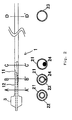
- Figs. 2 and 3 One example of the balloon catheters used in the present invention is explained in detail using Figs. 2 and 3.
- the shaft 1 consists of a distal section, a transition section and a proximal section, in which the distal section 12 extending from the guidewire port 11 is about 200 mm to 300 mm and is flexible, and the proximal section extending from the guidewire port 11 is about 700 to 1400 mm and is stiff.
- the distal section of the shaft 1 comprises double tubes composed of an inner tube 22 inside an outer tube 21 (Fig. 2 A-A' and Fig. B-B'), in which the distal end of the outer tube 21 is jointed with a most proximal end 35 of the balloon 3, and the inner lumen of the outer tube 21 communicates with the inside of the balloon 3.
- the inner tube 22 extends from the jointed part between the outer tube 21 and the balloon 3 toward the distal section to penetrate through the inside of the balloon 3, and the most distal end 31 of the balloon 3 is jointed with the peripheral surface of the distal section of the inner tube 22.
- the outer tube 21 and the inner tube 22 are made from synthetic materials such as polyamide or polyamide elastomer, but the synthetic materials are not limited to these materials.
- the inner tube 22 terminates at the guidewire port 11 through which the guidewire (not shown) can be drawn away, and the guidewire port 11 is provided on the tubular wall of the tube 21 (Fig.2 C-C').
- the proximal section of the shaft 1 is a single tube 23 forming a stiff proximal section connected with the outer tube 21, and is composed of a metallic material such as stainless steal, SUS 304, polyimide or polyetherketone (Fig. 2 D-D').
- the transition section of shaft 11 is a section in the proximal section and distal section in which the core wire is inserted.
- a core wire 24 made of a metallic material such as SUS 304 may be inserted in the proximal section of the outer tube 21 and the distal section of the outer tube 23 (Fig.2, B-B' and C-C', black circle).
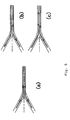
- the balloon 3 in the present invention consists of the balloon most distal portion (distal end) 31, a distal tapered portion 32, a balloon straight portion 33, a proximal tapered portion 34 and a most proximal portion 35 (proximal end) (Fig. 3).
- the distal portion 2 extending from the balloon straight portion 33 toward the distal side refers to the most distal end portion (distal end) 31 and the distal tapered portion 32.
- the balloon in the present invention is a balloon for medical instruments which is a given length of tube made of polymer materials and can be expanded in a radial direction under pressure.
- the polymer materials in the balloon 3 include synthetic elastomers such as polyamide elastomer, polyester elastomer, polyurethane elastomer and the like, and polyamide elastomers include polyamide/polyether block copolymer, polyamide/polyester block copolymer and the like.
- the polyamide/polyether block copolymer consists of two or more hard segments of polyamide and two or more soft segments of polyether.
- the polyamide hard segments in the polyamide/polyether block copolymer are polyamide consisting of C6 or more higher carboxylic acids and C6 or more higher organic diamines, or C6 or more higher aliphatic ⁇ -amino acids, and the polyether soft segments consist of C2 to C10 diols.
- the polyamide/polyether block copolymer has an elasticity of 150,000 psi (1.034 x 10 9 Pa) or less, preferably, 50,000 to 120,000 psi (3.448 x 10 8 to 8.274 x 10 8 Pa), a hardness Shore D 60 or more, preferably, 65 to 75, and include the polyamide hard segments in an amount of 50% to 95 % by weight, preferably, 80 to 90 % by weight (based on the polyamide/polyether block copolymer).
- the polyamide segments and polyether segments have repeated segments of 5 to 10, in which the polyamide segments may be selected from the group consisting of nylon 12, nylon 11, nylon 9, nylon 6, nylon 6/12, nylon 6/11, nylon 6/9 and nylon 6/6.
- the polyether segments may be selected from the group consisting of polyethylene glycol, polypropylene glycol, poly(tetramethylene ether), poly(pentamethylene ether) and poly(hexamethylene glycol).
- polyamide/polyether block copolymers are sold commercially under the PEBAX trademark by Atofina, Japan, or Atomchem North Ameica, Inc.
- suitable commercially available polymers are the Pebax 33 series polymers with a hardness of 60 and above (Shore D scale) especially, Pebax 7033 and 6333.
- the balloon 3 in the present invention consists of the balloon most distal portion (distal end) 31, the distal tapered portion 32, the balloon straight portion 33, the proximal tapered portion 34 and the most proximal portion (proximal end) (Fig. 3).
- the most distal portion 31 has a diameter of 0.4 to 0.7 mm and a length of 2 to 6 mm and the balloon straight portion 33 has a diameter of 0.8 to 7.0 mm and a length of 5 to 40 mm.
- a diameter of the most proximal portion is not limited in the present invention.
- the distal tapered portion 32 and the proximal tapered portion 34 are a transient portions from the most distal portion 31 to the balloon straight portion 33, and from the balloon straight portion 33 to the proximal portion 35, respectively.
- the thickness of the balloon is 15 to 40 ⁇ m, and the highest dilation ratio of the balloon straight portion is 4 to 8 times.
- the lubrication processing refers to film-formation by application of a silicon solution, or hydrophilization processing by applying a hydrophilic polymer solution, such as polyvinylpyrrolidone solution.
- the distal portion 2 and the balloon straight portion 33 in the balloon in the present invention include the following embodiments;
- the silicone useful in the present invention includes dimethylsilicone, MXD4 or DC-360 manufactured by Dow Corning, and the solvent includes flon, heptane and the like.
- the hydrophilic polymer useful in the present invention includes polyvinylpyrrolidones such as poly(vinylpyrrolidone) homopolymer and poly(vinylpyrrolidone) copolymer, and polyalkylene glycols such as polyethylene glycol, alkoxy polyalkylene glycol.
- the useful solvent for the hydrophilic polymer includes polar solvents such as alcohols, glycols and water; aliphatic hydrocarbons such as heptane and hexane; aromatic hydrocarbons such as toluene and xylene; chlorinated hydrocarbons such as perchloroethylene, methylene chloride, chloroform, carbon tetrachloride, and 1,1,1-trichloroethane; and fluorinated carbons.
- polar solvents such as alcohols, glycols and water
- aliphatic hydrocarbons such as heptane and hexane
- aromatic hydrocarbons such as toluene and xylene
- chlorinated hydrocarbons such as perchloroethylene, methylene chloride, chloroform, carbon tetrachloride, and 1,1,1-trichloroethane
- fluorinated carbons such as perchloroethylene, methylene chloride, chloroform, carbon tetrachlor
- a 5 % or less solution, preferably, a 5% to 10% solution of the hydrophilic polymer is used for hydrophilization processing.
- the method for coating the most distal portion, the distal tapered portion and the balloon straight portion in the balloon with the silicone solution or the hydrophilic polymer solution includes dipping, coating, spraying and the like.
- the coating thickness after evaporating the solvent is 1 to 10 ⁇ m, preferably, 2 to 6 ⁇ m, and most preferably, 2 to 4 ⁇ m.
- the solvent may be evaporated at ambient temperature.
- the gripping property represents an ability to prevent slipping from easily occurring, namely, stability in an objective area, in the case where a balloon guided to an objective area moves by slipping when the balloon is expanded during treatment using kissing techniques or treatment of in-stent restenosis (restenosis occurring in a stent).
- gripping property is expressed by a resistance value which is obtained when a balloon of a length of 20 mm and a folding diameter of 0.7 mm is fitted into a polyurethane tube of diameter 2.4 mm and length 10 mm and the balloon is expanded to a diameter of 2.5 mm and pulled toward a proximal side at a speed of 250 mm/min in a water bath of 37°C.
- the cross ability represents an ability to cross to an objective area and is expressed by a resistance value which is obtained when a balloon of length 20 mm and folding diameter 0.7 mm which is expanded to a diameter of 2.5 mm is pushed and inserted into a hole of a polyurethane film having a thickness of 1 mm and a hole diameter of 0.4 mm at a speed of 500 mm/min in a water bath of 37°C. Since better gripping property produces low cross ability, in the invention, both are adjusted with good balance.
- the gripping property is adjusted to 3.2 N to 6.0 N, and the cross ability is adjusted so that its initial value (when the balloon starts to be inserted) is not higher than 0.65 N and its middle value is not higher than 0.40 N.
- the gripping property is 4.0 N to 6.0 N, and the cross ability is adjusted so that its initial value is not higher than 0.50 N and its middle value is not higher than 0.39 N.
- the balance of gripping property and cross ability depends on its forming materials and the states of its surfaces as well as the balance between the stiffness of the proximal side of the shaft 1 and the flexibility of the distal section 12, and therefore, the balloon straight portion 33 and the distal portion 2 extending from the balloon straight portion 33 on a distal side (the most distal portion 31 and the distal tapered portion 32) generally are not subjected to lubrication processing.
- the distal portion 2 extending from the balloon straight portion 33 may also be subjected to lubrication processing in order to improve the cross ability, particularly the initial value of the cross ability, while maintaining the gripping property, and as a method for lubrication processing, because of the ease of processing, a 5 % or less silicone solution using flon as a solvent may be coated to form a film of silicone (lubricant).
- a 1 % polyvinylpyrrolidone solution using chloroform as solvent may also be coated on the distal portion.
- a 0.5 % or less silicone solution using flon as a solvent may also be coated to form a film of silicone on the balloon.
- a balloon 3 having a folding diameter of 0.74 mm and a thickness of 20 ⁇ m was formed by melting and extruding a polyamide/polyether block copolymer (PEBAX 7033 manufactured by Atofina Japan) into a balloon.
- the lengths of the balloon portions respectively are as follows; the most distal portion 31, 3 mm; the distal tapered portion 32, 4 mm; the straight portion 33, 20 mm; the proximal tapered portion 34, 3 mm and the most proximal portion 35, 2 mm.
- the inside of the most distal portion 31 in the balloon 3 was jointed to the peripheral surface of the polyamide inner tube 22 at the distal end, and the inside of the most proximal portion 35 in the balloon 3 was jointed to the peripheral surface of the polyamide outer tube 21 at the distal end to form the balloon catheter.
- the polyamide/polyether block copolymer (PEBAX 7033) has a Shore D hardness of 69, a flexural modulus of an 67,000, ultimate tensile strength of 8,300 psi, and an ultimate elongation of 400%.
- polyamide 12 or a blend of polyamide 12 and polyamide/polyether block copolymer (PEBAX 5533, Shore D hardness 55, manufactured by Atofina Japan, blend ratio 90/10 by weight) is used for making a balloon (Comparative Examples 3 and 5). Further, for the comparison, commercially available balloon catheters were prepared (Comparative Examples 1, 2 and 4 to 9).
- the balloon catheter according to the invention it is possible to perform treatment of a bifurcation safely and reliably, because the balloon catheter has a high ability to cross to an objective area and causes no slipping during kissing during treatment of a stenosis formed in a bifurcation of a blood vessel.
Landscapes
- Health & Medical Sciences (AREA)
- Life Sciences & Earth Sciences (AREA)
- Heart & Thoracic Surgery (AREA)
- Animal Behavior & Ethology (AREA)
- General Health & Medical Sciences (AREA)
- Public Health (AREA)
- Veterinary Medicine (AREA)
- Biophysics (AREA)
- Epidemiology (AREA)
- Child & Adolescent Psychology (AREA)
- Pulmonology (AREA)
- Engineering & Computer Science (AREA)
- Anesthesiology (AREA)
- Biomedical Technology (AREA)
- Hematology (AREA)
- Media Introduction/Drainage Providing Device (AREA)
- Materials For Medical Uses (AREA)
Abstract
Description


Claims (16)
- A balloon catheter suited to kissing techniques which comprises a tubular body having a balloon (3) provided on a flexible distal section (12) of a shaft (1), the balloon (3) comprising a most distal end portion (31), a distal tapered portion (32), a balloon straight portion (33), a proximal tapered portion (34) and a most proximal end portion (35), the shaft (1) comprising the flexible distal section (12), a transient section and a stiff proximal section, wherein the balloon catheter has a gripping property and cross ability adjusted with good balance.
- The balloon catheter according to claim 1, wherein the gripping property is 3.2 N to 6.0 N, which value is obtained when a balloon having a length of 20 mm and a folding diameter 0.7 mm is fitted into a polyurethane tube having a diameter of 2.4 mm and a length of 10 mm and the balloon is expanded to a diameter of 2.5 mm and pulled toward a proximal side of said tube at a speed of 250 mm/min in a water bath of 37°C; and wherein the cross ability is not higher than 0.65 N in initial value and not higher than 0.40 N in middle value, which value are obtained when a balloon of length 20 mm and folding diameter 0.7 mm which is expanded to a diameter of 2.5 mm is pushed and inserted into a hole having a diameter of 0.4 mm in a polyurethane film having a thickness of 1 mm at a speed of 500 mm/min in a water bath of 37°C.
- The balloon catheter according to claim 2, wherein the gripping property is 4.0 N to 6.0 N and the cross ability is not higher than 0.50 N in initial value and not higher than 0.39 N in middle value.
- The balloon catheter according to any one of the preceding claims, wherein the balloon straight portion (33) is not lubricated or has a silicone coating formed by applying a 0.5% or less silicone solution thereon.
- The balloon catheter according to any one of claims 1 to 3, wherein the most distal end portion (31), the distal tapered portion (32) and the balloon straight portion (33) are not lubricated.
- The balloon catheter according to any one of claims 1 to 3, wherein the most distal end portion (31) and the distal tapered portion (32) are lubricated while the balloon straight portion (33) is not lubricated.
- The balloon catheter according to claim 6, wherein the most distal end portion (31) and the distal tapered portion (32) have a polyvinylpyrrolidone coating.
- The balloon catheter according to claim 6, wherein the most distal end portion (31) and the distal tapered portion (32) have a silicone coating formed by applying a 5% or less silicone solution thereon.
- The balloon catheter according to any one of claims 1 to 3, wherein the most distal end portion (31), the distal tapered portion (32) and the balloon straight portion (33) are lubricated, and the most distal end portion (31) and the distal tapered portion (32) have a silicone coating formed by applying a 5% or less silicone solution thereon and the balloon straight portion (33) has a silicone coating formed by applying a 0.5% or less silicone solution thereon.
- The balloon catheter according to anyone of claims 1 to 3, wherein the most distal end portion (31), the distal tapered portion (32) and the balloon straight portion (33) are lubricated, and the most distal end portion (31) and the distal tapered portion (32) have a polyvinylpyrrolidone coating formed by applying a polyvinyl solution thereon and the balloon straight portion (33) has a silicone coating formed by applying a 0.5% or less silicone solution thereon.
- The balloon catheter according to any one of claims 1 to 3, wherein the most distal end portion (31) and the distal tapered portion (32) are not lubricated while the balloon straight portion (33) has a silicone coating formed by applying a 0.5% or less silicone solution thereon.
- The balloon catheter according to any one of the preceding claims, wherein the balloon (3) is made of a polyamide elastomer.
- The balloon catheter according to claim 12, wherein the polyamide elastomer is a polyamide/polyether block copolymer consisting of two or more hard segments of polyamide and two or more soft segments of polyether.
- The balloon catheter according to claim 12 or 13, wherein the polyamide/polyether block copolymer has a Shore D hardness of 60 or more, and the polyamide hard segments comprise 50% to 95 % by weight of the polyamide/polyether block copolymer.
- The balloon catheter according to claim 13, wherein the polyamide hard segments in the polyamide/polyether block copolymer are of a polyamide consisting of C6 or more higher carboxylic acids and C6 or more higher organic diamines, or C6 or more higher aliphatic ω-amino acids, and wherein the polyether soft segments consist of C2 to C10 diols.
- The balloon catheter according to any one of the preceding claims, wherein the shaft (1) comprises, as the flexible distal section (12), double tubes composed of an inner tube inside (22) an outer tube (21) made of synthetic polymer, and, as the stiff proximal section, a single tube (23) made of metallic material, polyimide or polyetherketone and connected with said outer tube (21).
Applications Claiming Priority (2)
| Application Number | Priority Date | Filing Date | Title |
|---|---|---|---|
| JP2003173902 | 2003-06-18 | ||
| JP2003173902 | 2003-06-18 |
Publications (3)
| Publication Number | Publication Date |
|---|---|
| EP1488822A2 true EP1488822A2 (en) | 2004-12-22 |
| EP1488822A3 EP1488822A3 (en) | 2005-05-04 |
| EP1488822B1 EP1488822B1 (en) | 2007-01-10 |
Family
ID=33410962
Family Applications (1)
| Application Number | Title | Priority Date | Filing Date |
|---|---|---|---|
| EP04014351A Expired - Lifetime EP1488822B1 (en) | 2003-06-18 | 2004-06-18 | Balloon catheter suited to kissing techniques |
Country Status (3)
| Country | Link |
|---|---|
| US (1) | US7407507B2 (en) |
| EP (1) | EP1488822B1 (en) |
| DE (1) | DE602004004199T2 (en) |
Cited By (2)
| Publication number | Priority date | Publication date | Assignee | Title |
|---|---|---|---|---|
| US7654264B2 (en) | 2006-07-18 | 2010-02-02 | Nellcor Puritan Bennett Llc | Medical tube including an inflatable cuff having a notched collar |
| CN108064179A (en) * | 2016-09-05 | 2018-05-22 | 朝日英达科株式会社 | Seal wire |
Families Citing this family (9)
| Publication number | Priority date | Publication date | Assignee | Title |
|---|---|---|---|---|
| US8177829B2 (en) * | 2006-08-23 | 2012-05-15 | Boston Scientific Scimed, Inc. | Auxiliary balloon catheter |
| JP4562197B2 (en) * | 2006-09-29 | 2010-10-13 | 朝日インテック株式会社 | Balloon catheter assembly |
| US8257722B2 (en) | 2008-09-15 | 2012-09-04 | Cv Ingenuity Corp. | Local delivery of water-soluble or water-insoluble therapeutic agents to the surface of body lumens |
| US9198968B2 (en) | 2008-09-15 | 2015-12-01 | The Spectranetics Corporation | Local delivery of water-soluble or water-insoluble therapeutic agents to the surface of body lumens |
| US8114429B2 (en) | 2008-09-15 | 2012-02-14 | Cv Ingenuity Corp. | Local delivery of water-soluble or water-insoluble therapeutic agents to the surface of body lumens |
| US8128951B2 (en) * | 2008-09-15 | 2012-03-06 | Cv Ingenuity Corp. | Local delivery of water-soluble or water-insoluble therapeutic agents to the surface of body lumens |
| JP5952562B2 (en) * | 2012-01-05 | 2016-07-13 | 株式会社グッドマン | Catheter and method for manufacturing catheter |
| US9956385B2 (en) | 2012-06-28 | 2018-05-01 | The Spectranetics Corporation | Post-processing of a medical device to control morphology and mechanical properties |
| US10525171B2 (en) | 2014-01-24 | 2020-01-07 | The Spectranetics Corporation | Coatings for medical devices |
Family Cites Families (9)
| Publication number | Priority date | Publication date | Assignee | Title |
|---|---|---|---|---|
| US4896670A (en) * | 1988-04-19 | 1990-01-30 | C. R. Bard, Inc. | Kissing balloon catheter |
| CA2107998C (en) | 1992-10-09 | 2005-09-20 | Makoto Onishi | Catheter-balloon for vasodilation |
| US5670558A (en) | 1994-07-07 | 1997-09-23 | Terumo Kabushiki Kaisha | Medical instruments that exhibit surface lubricity when wetted |
| US6306144B1 (en) | 1996-11-01 | 2001-10-23 | Scimed Life Systems, Inc. | Selective coating of a balloon catheter with lubricious material for stent deployment |
| JP3432101B2 (en) | 1997-02-06 | 2003-08-04 | テルモ株式会社 | Medical equipment |
| US6221467B1 (en) | 1997-06-03 | 2001-04-24 | Scimed Life Systems, Inc. | Coating gradient for lubricious coatings on balloon catheters |
| US6193686B1 (en) | 1999-06-30 | 2001-02-27 | Advanced Cardiovascular Systems, Inc. | Catheter with enhanced flexibility |
| AU2001247425A1 (en) | 2000-04-10 | 2001-10-23 | Advanced Cardiovascular Systems Inc. | Selectively coated stent delivery system and method of manufacture thereof |
| US7025752B2 (en) | 2002-11-06 | 2006-04-11 | Advanced Cardiovascular Systems, Inc. | Reduced slippage balloon catheter and method of using same |
-
2004
- 2004-06-17 US US10/868,937 patent/US7407507B2/en not_active Expired - Fee Related
- 2004-06-18 EP EP04014351A patent/EP1488822B1/en not_active Expired - Lifetime
- 2004-06-18 DE DE602004004199T patent/DE602004004199T2/en not_active Expired - Fee Related
Cited By (3)
| Publication number | Priority date | Publication date | Assignee | Title |
|---|---|---|---|---|
| US7654264B2 (en) | 2006-07-18 | 2010-02-02 | Nellcor Puritan Bennett Llc | Medical tube including an inflatable cuff having a notched collar |
| US8096299B2 (en) | 2006-07-18 | 2012-01-17 | Nellcor Puritan Bennett Llc | Medical tube including an inflatable cuff having a notched collar |
| CN108064179A (en) * | 2016-09-05 | 2018-05-22 | 朝日英达科株式会社 | Seal wire |
Also Published As
| Publication number | Publication date |
|---|---|
| DE602004004199D1 (en) | 2007-02-22 |
| DE602004004199T2 (en) | 2007-10-11 |
| US20040260330A1 (en) | 2004-12-23 |
| US7407507B2 (en) | 2008-08-05 |
| EP1488822B1 (en) | 2007-01-10 |
| EP1488822A3 (en) | 2005-05-04 |
Similar Documents
| Publication | Publication Date | Title |
|---|---|---|
| US6221467B1 (en) | Coating gradient for lubricious coatings on balloon catheters | |
| EP2334347B1 (en) | Multilayer medical balloon | |
| AU638936B2 (en) | Nylon-peba copolymer catheter | |
| US5368048A (en) | Method of making radio-opaque tipped, sleeved guidewire and product | |
| US6837869B2 (en) | Catheter having a soft distal tip | |
| CN103282075B (en) | Balloon Catheters with Adjustable Length and Diameter | |
| US7425357B2 (en) | Surface modification of expanded ultra high molecular weight polyethylene(eUHMWPE) for improved bondability | |
| US6610068B1 (en) | Non-flush over-the-wire catheter devices | |
| EP1488822B1 (en) | Balloon catheter suited to kissing techniques | |
| US20020018866A1 (en) | Polyether block amide catheter balloons | |
| JP4865188B2 (en) | Balloon catheter with striped flexible tip | |
| EP0277369A2 (en) | Dilatation catheter with angled balloon | |
| US20040002727A1 (en) | Coil reinforced catheter inner tubular member | |
| US20090254113A1 (en) | Dilatation balloon with ridges and methods | |
| KR20140121852A (en) | Medical tube | |
| US20040122464A1 (en) | Balloon catheter having a microporous distal tip | |
| JP2005028118A (en) | Balloon catheter suitable for kissing technique | |
| WO2024262530A1 (en) | Balloon catheter | |
| JP2007000157A (en) | Balloon and balloon catheter | |
| US20250152922A1 (en) | Balloon catheter | |
| WO2010060888A1 (en) | Medical balloon catheter with hollow wire cable rope guidewire duct | |
| WO2024070306A1 (en) | Balloon catheter | |
| WO2025047651A1 (en) | Catheter | |
| JP2003117003A (en) | Variable length balloon catheter and method of manufacturing the same |
Legal Events
| Date | Code | Title | Description |
|---|---|---|---|
| PUAI | Public reference made under article 153(3) epc to a published international application that has entered the european phase |
Free format text: ORIGINAL CODE: 0009012 |
|
| AK | Designated contracting states |
Kind code of ref document: A2 Designated state(s): AT BE BG CH CY CZ DE DK EE ES FI FR GB GR HU IE IT LI LU MC NL PL PT RO SE SI SK TR |
|
| AX | Request for extension of the european patent |
Extension state: AL HR LT LV MK |
|
| PUAL | Search report despatched |
Free format text: ORIGINAL CODE: 0009013 |
|
| AK | Designated contracting states |
Kind code of ref document: A3 Designated state(s): AT BE BG CH CY CZ DE DK EE ES FI FR GB GR HU IE IT LI LU MC NL PL PT RO SE SI SK TR |
|
| AX | Request for extension of the european patent |
Extension state: AL HR LT LV MK |
|
| RIC1 | Information provided on ipc code assigned before grant |
Ipc: 7A 61L 29/08 B Ipc: 7A 61L 29/14 B Ipc: 7A 61L 31/10 B Ipc: 7A 61M 25/00 B Ipc: 7A 61M 25/10 A Ipc: 7A 61M 29/02 B |
|
| 17P | Request for examination filed |
Effective date: 20051012 |
|
| AKX | Designation fees paid |
Designated state(s): AT BE BG CH CY CZ DE DK EE ES FI FR GB GR HU IE IT LI LU MC NL PL PT RO SE SI SK TR |
|
| GRAP | Despatch of communication of intention to grant a patent |
Free format text: ORIGINAL CODE: EPIDOSNIGR1 |
|
| GRAS | Grant fee paid |
Free format text: ORIGINAL CODE: EPIDOSNIGR3 |
|
| GRAA | (expected) grant |
Free format text: ORIGINAL CODE: 0009210 |
|
| AK | Designated contracting states |
Kind code of ref document: B1 Designated state(s): AT BE BG CH CY CZ DE DK EE ES FI FR GB GR HU IE IT LI LU MC NL PL PT RO SE SI SK TR |
|
| PG25 | Lapsed in a contracting state [announced via postgrant information from national office to epo] |
Ref country code: FI Free format text: LAPSE BECAUSE OF FAILURE TO SUBMIT A TRANSLATION OF THE DESCRIPTION OR TO PAY THE FEE WITHIN THE PRESCRIBED TIME-LIMIT Effective date: 20070110 Ref country code: AT Free format text: LAPSE BECAUSE OF FAILURE TO SUBMIT A TRANSLATION OF THE DESCRIPTION OR TO PAY THE FEE WITHIN THE PRESCRIBED TIME-LIMIT Effective date: 20070110 Ref country code: DK Free format text: LAPSE BECAUSE OF FAILURE TO SUBMIT A TRANSLATION OF THE DESCRIPTION OR TO PAY THE FEE WITHIN THE PRESCRIBED TIME-LIMIT Effective date: 20070110 Ref country code: NL Free format text: LAPSE BECAUSE OF FAILURE TO SUBMIT A TRANSLATION OF THE DESCRIPTION OR TO PAY THE FEE WITHIN THE PRESCRIBED TIME-LIMIT Effective date: 20070110 Ref country code: PL Free format text: LAPSE BECAUSE OF FAILURE TO SUBMIT A TRANSLATION OF THE DESCRIPTION OR TO PAY THE FEE WITHIN THE PRESCRIBED TIME-LIMIT Effective date: 20070110 Ref country code: LI Free format text: LAPSE BECAUSE OF FAILURE TO SUBMIT A TRANSLATION OF THE DESCRIPTION OR TO PAY THE FEE WITHIN THE PRESCRIBED TIME-LIMIT Effective date: 20070110 Ref country code: CH Free format text: LAPSE BECAUSE OF FAILURE TO SUBMIT A TRANSLATION OF THE DESCRIPTION OR TO PAY THE FEE WITHIN THE PRESCRIBED TIME-LIMIT Effective date: 20070110 Ref country code: SI Free format text: LAPSE BECAUSE OF FAILURE TO SUBMIT A TRANSLATION OF THE DESCRIPTION OR TO PAY THE FEE WITHIN THE PRESCRIBED TIME-LIMIT Effective date: 20070110 |
|
| REG | Reference to a national code |
Ref country code: GB Ref legal event code: FG4D |
|
| REG | Reference to a national code |
Ref country code: IE Ref legal event code: FG4D |
|
| REF | Corresponds to: |
Ref document number: 602004004199 Country of ref document: DE Date of ref document: 20070222 Kind code of ref document: P |
|
| PG25 | Lapsed in a contracting state [announced via postgrant information from national office to epo] |
Ref country code: SE Free format text: LAPSE BECAUSE OF FAILURE TO SUBMIT A TRANSLATION OF THE DESCRIPTION OR TO PAY THE FEE WITHIN THE PRESCRIBED TIME-LIMIT Effective date: 20070410 |
|
| PG25 | Lapsed in a contracting state [announced via postgrant information from national office to epo] |
Ref country code: BG Free format text: LAPSE BECAUSE OF FAILURE TO SUBMIT A TRANSLATION OF THE DESCRIPTION OR TO PAY THE FEE WITHIN THE PRESCRIBED TIME-LIMIT Effective date: 20070411 |
|
| PG25 | Lapsed in a contracting state [announced via postgrant information from national office to epo] |
Ref country code: ES Free format text: LAPSE BECAUSE OF FAILURE TO SUBMIT A TRANSLATION OF THE DESCRIPTION OR TO PAY THE FEE WITHIN THE PRESCRIBED TIME-LIMIT Effective date: 20070421 |
|
| ET | Fr: translation filed | ||
| PG25 | Lapsed in a contracting state [announced via postgrant information from national office to epo] |
Ref country code: PT Free format text: LAPSE BECAUSE OF FAILURE TO SUBMIT A TRANSLATION OF THE DESCRIPTION OR TO PAY THE FEE WITHIN THE PRESCRIBED TIME-LIMIT Effective date: 20070611 |
|
| NLV1 | Nl: lapsed or annulled due to failure to fulfill the requirements of art. 29p and 29m of the patents act | ||
| REG | Reference to a national code |
Ref country code: CH Ref legal event code: PL |
|
| PLBE | No opposition filed within time limit |
Free format text: ORIGINAL CODE: 0009261 |
|
| STAA | Information on the status of an ep patent application or granted ep patent |
Free format text: STATUS: NO OPPOSITION FILED WITHIN TIME LIMIT |
|
| PG25 | Lapsed in a contracting state [announced via postgrant information from national office to epo] |
Ref country code: SK Free format text: LAPSE BECAUSE OF FAILURE TO SUBMIT A TRANSLATION OF THE DESCRIPTION OR TO PAY THE FEE WITHIN THE PRESCRIBED TIME-LIMIT Effective date: 20070110 |
|
| 26N | No opposition filed |
Effective date: 20071011 |
|
| PG25 | Lapsed in a contracting state [announced via postgrant information from national office to epo] |
Ref country code: RO Free format text: LAPSE BECAUSE OF FAILURE TO SUBMIT A TRANSLATION OF THE DESCRIPTION OR TO PAY THE FEE WITHIN THE PRESCRIBED TIME-LIMIT Effective date: 20070110 Ref country code: CZ Free format text: LAPSE BECAUSE OF FAILURE TO SUBMIT A TRANSLATION OF THE DESCRIPTION OR TO PAY THE FEE WITHIN THE PRESCRIBED TIME-LIMIT Effective date: 20070110 Ref country code: BE Free format text: LAPSE BECAUSE OF FAILURE TO SUBMIT A TRANSLATION OF THE DESCRIPTION OR TO PAY THE FEE WITHIN THE PRESCRIBED TIME-LIMIT Effective date: 20070110 |
|
| PG25 | Lapsed in a contracting state [announced via postgrant information from national office to epo] |
Ref country code: MC Free format text: LAPSE BECAUSE OF NON-PAYMENT OF DUE FEES Effective date: 20070630 |
|
| PG25 | Lapsed in a contracting state [announced via postgrant information from national office to epo] |
Ref country code: GR Free format text: LAPSE BECAUSE OF FAILURE TO SUBMIT A TRANSLATION OF THE DESCRIPTION OR TO PAY THE FEE WITHIN THE PRESCRIBED TIME-LIMIT Effective date: 20070411 |
|
| PG25 | Lapsed in a contracting state [announced via postgrant information from national office to epo] |
Ref country code: IE Free format text: LAPSE BECAUSE OF NON-PAYMENT OF DUE FEES Effective date: 20070618 |
|
| PG25 | Lapsed in a contracting state [announced via postgrant information from national office to epo] |
Ref country code: EE Free format text: LAPSE BECAUSE OF FAILURE TO SUBMIT A TRANSLATION OF THE DESCRIPTION OR TO PAY THE FEE WITHIN THE PRESCRIBED TIME-LIMIT Effective date: 20070110 |
|
| PG25 | Lapsed in a contracting state [announced via postgrant information from national office to epo] |
Ref country code: CY Free format text: LAPSE BECAUSE OF FAILURE TO SUBMIT A TRANSLATION OF THE DESCRIPTION OR TO PAY THE FEE WITHIN THE PRESCRIBED TIME-LIMIT Effective date: 20070110 |
|
| PG25 | Lapsed in a contracting state [announced via postgrant information from national office to epo] |
Ref country code: LU Free format text: LAPSE BECAUSE OF NON-PAYMENT OF DUE FEES Effective date: 20070618 |
|
| PGFP | Annual fee paid to national office [announced via postgrant information from national office to epo] |
Ref country code: IT Payment date: 20090618 Year of fee payment: 6 |
|
| PG25 | Lapsed in a contracting state [announced via postgrant information from national office to epo] |
Ref country code: HU Free format text: LAPSE BECAUSE OF FAILURE TO SUBMIT A TRANSLATION OF THE DESCRIPTION OR TO PAY THE FEE WITHIN THE PRESCRIBED TIME-LIMIT Effective date: 20070711 Ref country code: TR Free format text: LAPSE BECAUSE OF FAILURE TO SUBMIT A TRANSLATION OF THE DESCRIPTION OR TO PAY THE FEE WITHIN THE PRESCRIBED TIME-LIMIT Effective date: 20070110 |
|
| PGFP | Annual fee paid to national office [announced via postgrant information from national office to epo] |
Ref country code: DE Payment date: 20090615 Year of fee payment: 6 Ref country code: GB Payment date: 20090617 Year of fee payment: 6 |
|
| GBPC | Gb: european patent ceased through non-payment of renewal fee |
Effective date: 20100618 |
|
| REG | Reference to a national code |
Ref country code: FR Ref legal event code: ST Effective date: 20110228 |
|
| PG25 | Lapsed in a contracting state [announced via postgrant information from national office to epo] |
Ref country code: IT Free format text: LAPSE BECAUSE OF NON-PAYMENT OF DUE FEES Effective date: 20100618 |
|
| PG25 | Lapsed in a contracting state [announced via postgrant information from national office to epo] |
Ref country code: DE Free format text: LAPSE BECAUSE OF NON-PAYMENT OF DUE FEES Effective date: 20110101 |
|
| PG25 | Lapsed in a contracting state [announced via postgrant information from national office to epo] |
Ref country code: FR Free format text: LAPSE BECAUSE OF NON-PAYMENT OF DUE FEES Effective date: 20100630 |
|
| PG25 | Lapsed in a contracting state [announced via postgrant information from national office to epo] |
Ref country code: GB Free format text: LAPSE BECAUSE OF NON-PAYMENT OF DUE FEES Effective date: 20100618 |
|
| PGFP | Annual fee paid to national office [announced via postgrant information from national office to epo] |
Ref country code: FR Payment date: 20090611 Year of fee payment: 6 |