EP1488709A1 - Improved dehydration system comprising a revolving screen - Google Patents
Improved dehydration system comprising a revolving screen Download PDFInfo
- Publication number
- EP1488709A1 EP1488709A1 EP03743397A EP03743397A EP1488709A1 EP 1488709 A1 EP1488709 A1 EP 1488709A1 EP 03743397 A EP03743397 A EP 03743397A EP 03743397 A EP03743397 A EP 03743397A EP 1488709 A1 EP1488709 A1 EP 1488709A1
- Authority
- EP
- European Patent Office
- Prior art keywords
- screen
- product
- revolving screen
- hot air
- dehydration system
- Prior art date
- Legal status (The legal status is an assumption and is not a legal conclusion. Google has not performed a legal analysis and makes no representation as to the accuracy of the status listed.)
- Granted
Links
- 230000018044 dehydration Effects 0.000 title claims abstract description 18
- 238000006297 dehydration reaction Methods 0.000 title claims abstract description 18
- 238000010908 decantation Methods 0.000 claims abstract description 7
- 238000010438 heat treatment Methods 0.000 claims abstract description 4
- 239000004449 solid propellant Substances 0.000 claims description 5
- 230000005484 gravity Effects 0.000 claims description 2
- 239000000835 fiber Substances 0.000 abstract description 16
- 239000000446 fuel Substances 0.000 abstract description 7
- 238000001035 drying Methods 0.000 abstract description 5
- 239000010849 combustible waste Substances 0.000 abstract 1
- 239000000047 product Substances 0.000 description 54
- 238000000034 method Methods 0.000 description 14
- ATUOYWHBWRKTHZ-UHFFFAOYSA-N Propane Chemical compound CCC ATUOYWHBWRKTHZ-UHFFFAOYSA-N 0.000 description 4
- 239000007789 gas Substances 0.000 description 4
- VNWKTOKETHGBQD-UHFFFAOYSA-N methane Chemical compound C VNWKTOKETHGBQD-UHFFFAOYSA-N 0.000 description 4
- 210000003027 ear inner Anatomy 0.000 description 3
- 241000219823 Medicago Species 0.000 description 2
- 235000017587 Medicago sativa ssp. sativa Nutrition 0.000 description 2
- 238000001816 cooling Methods 0.000 description 2
- 239000002283 diesel fuel Substances 0.000 description 2
- 238000010348 incorporation Methods 0.000 description 2
- 238000009434 installation Methods 0.000 description 2
- 238000012423 maintenance Methods 0.000 description 2
- 239000003345 natural gas Substances 0.000 description 2
- 239000002245 particle Substances 0.000 description 2
- 239000001294 propane Substances 0.000 description 2
- 239000002699 waste material Substances 0.000 description 2
- 244000144725 Amygdalus communis Species 0.000 description 1
- 235000011437 Amygdalus communis Nutrition 0.000 description 1
- 241000283690 Bos taurus Species 0.000 description 1
- 239000002154 agricultural waste Substances 0.000 description 1
- 238000003915 air pollution Methods 0.000 description 1
- 235000020224 almond Nutrition 0.000 description 1
- 230000015556 catabolic process Effects 0.000 description 1
- 235000013339 cereals Nutrition 0.000 description 1
- 238000002485 combustion reaction Methods 0.000 description 1
- 239000000428 dust Substances 0.000 description 1
- 239000000284 extract Substances 0.000 description 1
- 238000009313 farming Methods 0.000 description 1
- 238000011049 filling Methods 0.000 description 1
- 238000001914 filtration Methods 0.000 description 1
- 239000012467 final product Substances 0.000 description 1
- 239000002440 industrial waste Substances 0.000 description 1
- 238000009413 insulation Methods 0.000 description 1
- 239000007788 liquid Substances 0.000 description 1
- 230000014759 maintenance of location Effects 0.000 description 1
- 238000004519 manufacturing process Methods 0.000 description 1
- 238000012856 packing Methods 0.000 description 1
- 238000012545 processing Methods 0.000 description 1
- 230000000979 retarding effect Effects 0.000 description 1
- 238000000926 separation method Methods 0.000 description 1
- 238000003756 stirring Methods 0.000 description 1
- 210000003462 vein Anatomy 0.000 description 1
Images
Classifications
-
- A—HUMAN NECESSITIES
- A23—FOODS OR FOODSTUFFS; TREATMENT THEREOF, NOT COVERED BY OTHER CLASSES
- A23B—PRESERVATION OF FOODS, FOODSTUFFS OR NON-ALCOHOLIC BEVERAGES; CHEMICAL RIPENING OF FRUIT OR VEGETABLES
- A23B7/00—Preservation of fruit or vegetables; Chemical ripening of fruit or vegetables
- A23B7/02—Dehydrating; Subsequent reconstitution
- A23B7/0205—Dehydrating; Subsequent reconstitution by contact of the material with fluids, e.g. drying gas or extracting liquids
-
- A—HUMAN NECESSITIES
- A23—FOODS OR FOODSTUFFS; TREATMENT THEREOF, NOT COVERED BY OTHER CLASSES
- A23B—PRESERVATION OF FOODS, FOODSTUFFS OR NON-ALCOHOLIC BEVERAGES; CHEMICAL RIPENING OF FRUIT OR VEGETABLES
- A23B7/00—Preservation of fruit or vegetables; Chemical ripening of fruit or vegetables
- A23B7/02—Dehydrating; Subsequent reconstitution
-
- A—HUMAN NECESSITIES
- A23—FOODS OR FOODSTUFFS; TREATMENT THEREOF, NOT COVERED BY OTHER CLASSES
- A23B—PRESERVATION OF FOODS, FOODSTUFFS OR NON-ALCOHOLIC BEVERAGES; CHEMICAL RIPENING OF FRUIT OR VEGETABLES
- A23B9/00—Preservation of edible seeds, e.g. cereals
- A23B9/08—Drying; Subsequent reconstitution
-
- A—HUMAN NECESSITIES
- A23—FOODS OR FOODSTUFFS; TREATMENT THEREOF, NOT COVERED BY OTHER CLASSES
- A23N—MACHINES OR APPARATUS FOR TREATING HARVESTED FRUIT, VEGETABLES OR FLOWER BULBS IN BULK, NOT OTHERWISE PROVIDED FOR; PEELING VEGETABLES OR FRUIT IN BULK; APPARATUS FOR PREPARING ANIMAL FEEDING- STUFFS
- A23N12/00—Machines for cleaning, blanching, drying or roasting fruits or vegetables, e.g. coffee, cocoa, nuts
- A23N12/08—Machines for cleaning, blanching, drying or roasting fruits or vegetables, e.g. coffee, cocoa, nuts for drying or roasting
-
- F—MECHANICAL ENGINEERING; LIGHTING; HEATING; WEAPONS; BLASTING
- F26—DRYING
- F26B—DRYING SOLID MATERIALS OR OBJECTS BY REMOVING LIQUID THEREFROM
- F26B11/00—Machines or apparatus for drying solid materials or objects with movement which is non-progressive
- F26B11/02—Machines or apparatus for drying solid materials or objects with movement which is non-progressive in moving drums or other mainly-closed receptacles
- F26B11/026—Arrangements for charging or discharging the materials to be dried, e.g. discharging by reversing drum rotation, using spiral-type inserts
-
- F—MECHANICAL ENGINEERING; LIGHTING; HEATING; WEAPONS; BLASTING
- F26—DRYING
- F26B—DRYING SOLID MATERIALS OR OBJECTS BY REMOVING LIQUID THEREFROM
- F26B11/00—Machines or apparatus for drying solid materials or objects with movement which is non-progressive
- F26B11/02—Machines or apparatus for drying solid materials or objects with movement which is non-progressive in moving drums or other mainly-closed receptacles
- F26B11/028—Arrangements for the supply or exhaust of gaseous drying medium for direct heat transfer, e.g. perforated tubes, annular passages, burner arrangements, dust separation, combined direct and indirect heating
-
- F—MECHANICAL ENGINEERING; LIGHTING; HEATING; WEAPONS; BLASTING
- F26—DRYING
- F26B—DRYING SOLID MATERIALS OR OBJECTS BY REMOVING LIQUID THEREFROM
- F26B23/00—Heating arrangements
- F26B23/02—Heating arrangements using combustion heating
- F26B23/028—Heating arrangements using combustion heating using solid fuel; burning the dried product
Definitions
- the present descriptive memory refers, as its title indicates, to an improved dehydration system comprising a revolving screen, of the type used to dehydrate or dry different types of agricultural products, like alfalfa, any kind of fodder, pulps, cereal and agricultural or urban waste, with the main purpose of improving the conservation of those products since they are harvested or produced until they are consumed or used.
- a revolving screen or tube where the product that has to be dehydrated is introduced at one end, usually by means of a feed hopper.
- the revolving motion of the screen usually generated by means of external driving wheels, together with the internal blades or ribs turn the product as it moves lengthways along the screen.
- Hot air is also introduced into the screen at the same end as the product.
- the hot air comes from a gas burner (e.g. natural gas, propane or similar) or an oil burner (e.g. diesel fuel). This air circulates through the screen because a powerful fan situated at the exit sucks it.
- a sluice stops most of the product, specially medium-sized and large fibres, in order to separate it from the hot air current, and from there it arrives at the exit tank by means of pipes and feed augers.
- the product can go through any type of cooling system in order to lower its temperature. The hot air is sucked through the screen together with some airborne product, mainly small and very small fibres.
- the hot air has to go through a cyclone or decantation labyrinth with a large sluice where the product is separated from the air in order to incorporate it to the next process.
- the fan situated at the exit used to suck the air during the circulation process, expels all that air out of the system, usually through a ventilating stack.
- the need for a high degree of dehydration in the fibre requires the hot air used in the process to be at very high temperatures, around 700 °C. In order to reach those temperatures it is necessary to use high performance gas or oil burners, which consume a lot of energy to heat the air from room temperature to the desired temperature. This high consumption increases the cost of the dehydration process and therefore the price of the final product. It has the additional disadvantage of generating high levels of air pollution. This means that complex filtering systems have to be installed in the chimneys, and this increases the cost of the installation.
- the improved dehydration system comprising a revolving screen that is the subject of the present invention has been developed. It includes several fundamental innovations that combined solve all the problems and disadvantages of the systems currently used to process long fibre products, and also improve enormously the energy efficiency of the whole system, which in turn means lower costs.
- the first innovation is a drying screen perfected with a system of internal mutiturn blades that turn and stir the product more, so that it mixes better with the hot air and the dehydration is improved without it getting stuck or forming obstacles that slow it down. Therefore, the product flows easily and continuously, regardless of the length of the fibre. This way, the product does not get stuck and the system does not break down when processing long fibre products. Therefore the process is improved and maintenance costs are lower.
- Another important innovation is the incorporation of a decantation unit at the exit of the screen, which replaces the separating sluice in the conventional systems. The product falls by gravity from this box onto the exit conveyor and is thus separated from the hot air without any kind of mechanism that might limit the size of the processed product. This way, another source of constant breakdowns and bottlenecks is eliminated and long fibre products can be easily separated.
- a great improvement over conventional processes is the incorporation of a mixed hot air generator that basically has a preheating stage, based on the combustion of solid fuels (biomasses or similar), followed by an air propelling fan, and a second heating stage at high temperatures based on a gas (natural gas, propane, etc.) or liquid (e.g. diesel fuel) burner, or otherwise, resistors or heat exchangers that generate electric power.
- the first stage heats the air, raising its temperature to about 350 °C, by means of a solid fuel furnace where biomasses (agricultural waste such as almond shells, etc.) or other kind of low cost solid fuels are burned.
- the air at 350 °C is then propelled by means of a fan into the second stage, where its temperature is raised using burners, resistors or heat exchangers to more than 700 °C, which is the temperature required to dehydrated the product properly in the screen.
- This kind of mixed hot air generator has an important advantage: the fuels that are burned in the furnace during the preheating stage, such as biomasses and other farming or industrial waste, are very low cost fuels. This is a low cost and environmentally friendly contribution to waste disposal. This obviously reduces significantly the cost of the process, also because during the second stage, which uses more expensive fuels, the product is already heated and the temperature difference, in this case between 350 °C and 700 °C, is smaller than with conventional generators, and therefore less fuel is required.
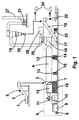
- figure -1- shows a lateral view of the present invention.
- the drying process starts with a feeding system (1) where the wet product is placed.
- the product is moved up by a conveyor (2) that consists of a conveyor belt, feed auger or similar and into the inlet (3) of the revolving screen (4).
- the amount of product that goes in can be controlled by adjusting the speed of the conveyor and the thickness of the product layer changing the height of a roll (5).
- the product falls into the screen's inlet (3) through a large pipe, preventing blockages.
- the wet product and the hot air from the mixed furnace (6) enter the screen (4) through a pipe (7) that is insulated in order to prevent the loss of heat and has the inlet (3) at the top.
- the hot air generator (6) has two stages. The first one preheats the air in a chamber (8) using a solid fuel burner with its own fuel feeding system (9), made of a feed hopper and a feed auger or similar. At the exit there is an ash and particles decanter (10), fitted with thermal insulation, and a fan (11) that propels the preheated air. Next, the second heating stage takes place in another chamber (12) where there is a high performance burner, preferably an "air vein” type gas burner, although it can be of other types of fuel or even electrical, like an air-to-air heat exchanger.
- a high performance burner preferably an "air vein” type gas burner, although it can be of other types of fuel or even electrical, like an air-to-air heat exchanger.
- the drying system being put forward is a perfected one-step multiturn revolving screen (4) where the product forms curtains as it falls from the revolving blades and is thus exposed to the airflow.
- the screen (4) has treads (13) that allow it to turn on top of several wheels or bearings, one of which, at least, is a driving one (14). All this rests on top of beds or mountings (15) tightly anchored to a bedplate.
- a decantation unit (16) attached to the reception hopper (17) followed by a conveyor (18) that takes the dry product out of the screen (4).
- the lighter particles that are carried by the air will be collected in a cyclone (19) or cyclonic separator that works in depression and separates the dust and fine dry product from the air.
- a revolving valve (20) at the bottom, and an indraught pipe connects it to the indraught fan (21).
- the revolving valve (20) extracts the fine product that can then be incorporated to the long fibre product or kept apart for a different kind of treatment.
- the exit conveyor (18) that carries the dry product also allows the fibre to cool down. Once the dry fibre has fallen from the decantation unit (16) at the beginning of the conveyor and as soon as it starts going up, it is subjected to a flow of cold air generated by a refrigerating unit (23) that lowers its temperature. At the exit of the conveyor we obtain the dry long fibre product, that can optionally be fed into a packing press (22).
Landscapes
- Engineering & Computer Science (AREA)
- Life Sciences & Earth Sciences (AREA)
- Chemical & Material Sciences (AREA)
- Food Science & Technology (AREA)
- Polymers & Plastics (AREA)
- General Engineering & Computer Science (AREA)
- Zoology (AREA)
- Wood Science & Technology (AREA)
- Mechanical Engineering (AREA)
- General Chemical & Material Sciences (AREA)
- Chemical Kinetics & Catalysis (AREA)
- Sustainable Development (AREA)
- Combustion & Propulsion (AREA)
- Physics & Mathematics (AREA)
- Thermal Sciences (AREA)
- Drying Of Solid Materials (AREA)
- Transplanting Machines (AREA)
- Separation Using Semi-Permeable Membranes (AREA)
- Centrifugal Separators (AREA)
- Filtering Materials (AREA)
Abstract
Description
Attempts to carry out this type of process with the current systems have revealed several problems and disadvantages.
Another important innovation is the incorporation of a decantation unit at the exit of the screen, which replaces the separating sluice in the conventional systems. The product falls by gravity from this box onto the exit conveyor and is thus separated from the hot air without any kind of mechanism that might limit the size of the processed product. This way, another source of constant breakdowns and bottlenecks is eliminated and long fibre products can be easily separated.
The hot air generator (6) has two stages. The first one preheats the air in a chamber (8) using a solid fuel burner with its own fuel feeding system (9), made of a feed hopper and a feed auger or similar. At the exit there is an ash and particles decanter (10), fitted with thermal insulation, and a fan (11) that propels the preheated air. Next, the second heating stage takes place in another chamber (12) where there is a high performance burner, preferably an "air vein" type gas burner, although it can be of other types of fuel or even electrical, like an air-to-air heat exchanger.
The screen (4) has treads (13) that allow it to turn on top of several wheels or bearings, one of which, at least, is a driving one (14). All this rests on top of beds or mountings (15) tightly anchored to a bedplate.
At the exit of the screen (4) there is a decantation unit (16) attached to the reception hopper (17) followed by a conveyor (18) that takes the dry product out of the screen (4).
The lighter particles that are carried by the air will be collected in a cyclone (19) or cyclonic separator that works in depression and separates the dust and fine dry product from the air. In order to do that, it is fitted with a revolving valve (20) at the bottom, and an indraught pipe connects it to the indraught fan (21).
The revolving valve (20) extracts the fine product that can then be incorporated to the long fibre product or kept apart for a different kind of treatment.
Claims (5)
- Improved dehydration system comprising a revolving screen, of the type used to dehydrate or dry different types of agricultural products, and characterized in that it uses a perfected multiturn revolving screen.
- Improved dehydration system comprising a revolving screen, as described in the previous claim, characterized in that at the exit of the screen the product falls by gravity from a sluice-free decantation unit (16), so that the dry product is separated from the hot air.
- Improved dehydration system comprising a revolving screen, as described in the previous claim, characterized by a mixed hot air generator (6) with two sequential heating stages (8) and (12).
- Improved dehydration system comprising a revolving screen, as described in the previous claim, characterized in that it can use solid fuels in the preheating stage (8).
- Improved dehydration system comprising a revolving screen, as described in the previous claim, characterized by two fans, (11) and (21), that improve the hot air flow inside the revolving screen (4) and through the whole dehydration system.
Applications Claiming Priority (3)
| Application Number | Priority Date | Filing Date | Title |
|---|---|---|---|
| ES200200502A ES2197800B1 (en) | 2002-03-01 | 2002-03-01 | IMPROVED DEHYDRATION SYSTEM IN ROTARY TROMEL. |
| ES200200502 | 2002-03-01 | ||
| PCT/ES2003/000091 WO2003073874A1 (en) | 2002-03-01 | 2003-02-26 | Improved dehydration system comprising a revolving screen |
Publications (2)
| Publication Number | Publication Date |
|---|---|
| EP1488709A1 true EP1488709A1 (en) | 2004-12-22 |
| EP1488709B1 EP1488709B1 (en) | 2005-08-03 |
Family
ID=27772019
Family Applications (1)
| Application Number | Title | Priority Date | Filing Date |
|---|---|---|---|
| EP03743397A Expired - Lifetime EP1488709B1 (en) | 2002-03-01 | 2003-02-26 | Improved dehydration system comprising a revolving screen |
Country Status (6)
| Country | Link |
|---|---|
| EP (1) | EP1488709B1 (en) |
| AT (1) | ATE300880T1 (en) |
| AU (1) | AU2003209779A1 (en) |
| DE (1) | DE60301209D1 (en) |
| ES (1) | ES2197800B1 (en) |
| WO (1) | WO2003073874A1 (en) |
Cited By (3)
| Publication number | Priority date | Publication date | Assignee | Title |
|---|---|---|---|---|
| CN104567283A (en) * | 2013-10-10 | 2015-04-29 | 宁夏琪凯节能设备有限公司 | Novel energy-saving slag dryer |
| CN106352690A (en) * | 2016-10-17 | 2017-01-25 | 无锡市日升化工有限公司 | PVC processing aid drying machine capable of drying in rotatable mode |
| WO2018187965A1 (en) * | 2017-04-12 | 2018-10-18 | 深圳市源畅通科技有限公司 | Grain drying device convenient to use |
Families Citing this family (6)
| Publication number | Priority date | Publication date | Assignee | Title |
|---|---|---|---|---|
| CN103528347A (en) * | 2013-11-05 | 2014-01-22 | 宁夏新航能源环境科技有限公司 | Energy-saving dryer |
| CN104390437A (en) * | 2014-10-24 | 2015-03-04 | 广德县瑞龙新型材料有限公司 | Fluorite dryer |
| CN105875828A (en) * | 2016-05-27 | 2016-08-24 | 黄莉娟 | Drum-type grain dryer |
| CN107263590B (en) * | 2017-07-05 | 2019-04-05 | 芜湖扬展新材料科技服务有限公司 | A kind of betel nut pelleter with cleaning and drying integrated function |
| CN109107891A (en) * | 2018-08-15 | 2019-01-01 | 绩溪袁稻农业产业科技有限公司 | Paddy processing system |
| CN112588576B (en) * | 2020-11-27 | 2022-02-01 | 日照金果粮油有限公司 | Peanut stir-frying device capable of achieving uniform heating |
Family Cites Families (5)
| Publication number | Priority date | Publication date | Assignee | Title |
|---|---|---|---|---|
| ES2014609A6 (en) * | 1989-04-25 | 1990-07-16 | Baque De Montiano Jose Antonio | Dryer for bulk (loose) products with a high level of moisture |
| ES2127051B1 (en) * | 1995-05-04 | 2000-01-01 | Ingenieria Del Secado S L | PERFECTED ROTARY DRYER FOR FOOD PRODUCTS. |
| ES1033784Y (en) * | 1996-04-03 | 1997-03-01 | Agro Pirineos Ayerbe S L | PERFECTED DRYER TROMEL. |
| ES2177359B2 (en) * | 1999-04-06 | 2003-12-01 | Ibergear S L | ROTARY DRYER. |
| ES1046567Y (en) * | 2000-06-20 | 2001-06-01 | Agro Pirineos Ayerbe S L | PERFECTED DEHYDRATION TROMEL. |
-
2002
- 2002-03-01 ES ES200200502A patent/ES2197800B1/en not_active Expired - Fee Related
-
2003
- 2003-02-26 AT AT03743397T patent/ATE300880T1/en not_active IP Right Cessation
- 2003-02-26 AU AU2003209779A patent/AU2003209779A1/en not_active Abandoned
- 2003-02-26 DE DE60301209T patent/DE60301209D1/en not_active Expired - Lifetime
- 2003-02-26 EP EP03743397A patent/EP1488709B1/en not_active Expired - Lifetime
- 2003-02-26 WO PCT/ES2003/000091 patent/WO2003073874A1/en not_active Ceased
Non-Patent Citations (1)
| Title |
|---|
| See references of WO03073874A1 * |
Cited By (3)
| Publication number | Priority date | Publication date | Assignee | Title |
|---|---|---|---|---|
| CN104567283A (en) * | 2013-10-10 | 2015-04-29 | 宁夏琪凯节能设备有限公司 | Novel energy-saving slag dryer |
| CN106352690A (en) * | 2016-10-17 | 2017-01-25 | 无锡市日升化工有限公司 | PVC processing aid drying machine capable of drying in rotatable mode |
| WO2018187965A1 (en) * | 2017-04-12 | 2018-10-18 | 深圳市源畅通科技有限公司 | Grain drying device convenient to use |
Also Published As
| Publication number | Publication date |
|---|---|
| AU2003209779A1 (en) | 2003-09-16 |
| ATE300880T1 (en) | 2005-08-15 |
| ES2197800B1 (en) | 2005-02-01 |
| ES2197800A1 (en) | 2004-01-01 |
| EP1488709B1 (en) | 2005-08-03 |
| DE60301209D1 (en) | 2005-09-08 |
| WO2003073874A1 (en) | 2003-09-12 |
Similar Documents
| Publication | Publication Date | Title |
|---|---|---|
| US20100089295A1 (en) | Continuously-Fed Non-Densified Biomass Combustion System | |
| US20120006025A1 (en) | Thermal power plant using low-grade coal as fuel | |
| EP1488709B1 (en) | Improved dehydration system comprising a revolving screen | |
| JP3359307B2 (en) | Method and apparatus for drying and carbonizing organic waste | |
| US5904105A (en) | Device for combustion of moist fuel | |
| US20130291771A1 (en) | Method and system for delivering heat through gasification of biomass | |
| CN116376578B (en) | Continuous carbonization method and equipment for biomass waste by utilizing aerodynamic method | |
| CN113819749A (en) | Hot air generating device for drying tea leaves | |
| CN112899003B (en) | Multifunctional full-automatic biomass carbonization system and biomass carbonization method | |
| CN207527967U (en) | A kind of paddle type sludge dryer | |
| US2696677A (en) | Dehydrator | |
| CN106196096B (en) | Bagasse boiler drying and spray combustion system | |
| CN221319879U (en) | High-temperature pyrolysis gasification furnace for solid waste | |
| CN211575831U (en) | A food oven dehumidification structure | |
| CN207845463U (en) | A kind of municipal sludge carbonization cracker | |
| CN219494741U (en) | Biomass fuel dehumidifying and drying device | |
| CN205351339U (en) | Dregs of a decoction biomass fuel multi -fuel fired boiler | |
| CN112944364B (en) | Semisolid hazardous waste incineration treatment process | |
| CN205747844U (en) | One crushed biomass band drier safely and efficiently | |
| US3738796A (en) | Apparatus and method for dehydrating wet particulate matter and for disposing of waste products therefrom | |
| CN111748393B (en) | A device for making solid fuel from kitchen waste by swirl flash self-heating and cascade utilization | |
| CN104946280B (en) | A kind of micro-wave drying and the integrated apparatus for being pyrolyzed marine alga | |
| CN204779474U (en) | Integrated device of microwave heating drying and pyrolysis marine alga | |
| CN202973115U (en) | Lifting spiral feeding device | |
| CN209456271U (en) | A kind of municipal sludge pyrolysis installation |
Legal Events
| Date | Code | Title | Description |
|---|---|---|---|
| PUAI | Public reference made under article 153(3) epc to a published international application that has entered the european phase |
Free format text: ORIGINAL CODE: 0009012 |
|
| 17P | Request for examination filed |
Effective date: 20040922 |
|
| AK | Designated contracting states |
Kind code of ref document: A1 Designated state(s): AT BE BG CH CY CZ DE DK EE ES FI FR GB GR HU IE IT LI LU MC NL PT SE SI SK TR |
|
| AX | Request for extension of the european patent |
Extension state: AL LT LV MK RO |
|
| GRAP | Despatch of communication of intention to grant a patent |
Free format text: ORIGINAL CODE: EPIDOSNIGR1 |
|
| GRAS | Grant fee paid |
Free format text: ORIGINAL CODE: EPIDOSNIGR3 |
|
| GRAA | (expected) grant |
Free format text: ORIGINAL CODE: 0009210 |
|
| AK | Designated contracting states |
Kind code of ref document: B1 Designated state(s): AT BE BG CH CY CZ DE DK EE ES FI FR GB GR HU IE IT LI LU MC NL PT SE SI SK TR |
|
| PG25 | Lapsed in a contracting state [announced via postgrant information from national office to epo] |
Ref country code: IT Free format text: LAPSE BECAUSE OF FAILURE TO SUBMIT A TRANSLATION OF THE DESCRIPTION OR TO PAY THE FEE WITHIN THE PRESCRIBED TIME-LIMIT;WARNING: LAPSES OF ITALIAN PATENTS WITH EFFECTIVE DATE BEFORE 2007 MAY HAVE OCCURRED AT ANY TIME BEFORE 2007. THE CORRECT EFFECTIVE DATE MAY BE DIFFERENT FROM THE ONE RECORDED. Effective date: 20050803 Ref country code: EE Free format text: LAPSE BECAUSE OF FAILURE TO SUBMIT A TRANSLATION OF THE DESCRIPTION OR TO PAY THE FEE WITHIN THE PRESCRIBED TIME-LIMIT Effective date: 20050803 Ref country code: FI Free format text: LAPSE BECAUSE OF FAILURE TO SUBMIT A TRANSLATION OF THE DESCRIPTION OR TO PAY THE FEE WITHIN THE PRESCRIBED TIME-LIMIT Effective date: 20050803 Ref country code: LI Free format text: LAPSE BECAUSE OF FAILURE TO SUBMIT A TRANSLATION OF THE DESCRIPTION OR TO PAY THE FEE WITHIN THE PRESCRIBED TIME-LIMIT Effective date: 20050803 Ref country code: SI Free format text: LAPSE BECAUSE OF FAILURE TO SUBMIT A TRANSLATION OF THE DESCRIPTION OR TO PAY THE FEE WITHIN THE PRESCRIBED TIME-LIMIT Effective date: 20050803 Ref country code: NL Free format text: LAPSE BECAUSE OF FAILURE TO SUBMIT A TRANSLATION OF THE DESCRIPTION OR TO PAY THE FEE WITHIN THE PRESCRIBED TIME-LIMIT Effective date: 20050803 Ref country code: SK Free format text: LAPSE BECAUSE OF FAILURE TO SUBMIT A TRANSLATION OF THE DESCRIPTION OR TO PAY THE FEE WITHIN THE PRESCRIBED TIME-LIMIT Effective date: 20050803 Ref country code: CH Free format text: LAPSE BECAUSE OF FAILURE TO SUBMIT A TRANSLATION OF THE DESCRIPTION OR TO PAY THE FEE WITHIN THE PRESCRIBED TIME-LIMIT Effective date: 20050803 Ref country code: AT Free format text: LAPSE BECAUSE OF FAILURE TO SUBMIT A TRANSLATION OF THE DESCRIPTION OR TO PAY THE FEE WITHIN THE PRESCRIBED TIME-LIMIT Effective date: 20050803 Ref country code: CZ Free format text: LAPSE BECAUSE OF FAILURE TO SUBMIT A TRANSLATION OF THE DESCRIPTION OR TO PAY THE FEE WITHIN THE PRESCRIBED TIME-LIMIT Effective date: 20050803 Ref country code: BE Free format text: LAPSE BECAUSE OF FAILURE TO SUBMIT A TRANSLATION OF THE DESCRIPTION OR TO PAY THE FEE WITHIN THE PRESCRIBED TIME-LIMIT Effective date: 20050803 Ref country code: TR Free format text: LAPSE BECAUSE OF FAILURE TO SUBMIT A TRANSLATION OF THE DESCRIPTION OR TO PAY THE FEE WITHIN THE PRESCRIBED TIME-LIMIT Effective date: 20050803 |
|
| REG | Reference to a national code |
Ref country code: GB Ref legal event code: FG4D |
|
| REG | Reference to a national code |
Ref country code: CH Ref legal event code: EP |
|
| REG | Reference to a national code |
Ref country code: IE Ref legal event code: FG4D |
|
| REF | Corresponds to: |
Ref document number: 60301209 Country of ref document: DE Date of ref document: 20050908 Kind code of ref document: P |
|
| PG25 | Lapsed in a contracting state [announced via postgrant information from national office to epo] |
Ref country code: BG Free format text: LAPSE BECAUSE OF FAILURE TO SUBMIT A TRANSLATION OF THE DESCRIPTION OR TO PAY THE FEE WITHIN THE PRESCRIBED TIME-LIMIT Effective date: 20051103 Ref country code: SE Free format text: LAPSE BECAUSE OF FAILURE TO SUBMIT A TRANSLATION OF THE DESCRIPTION OR TO PAY THE FEE WITHIN THE PRESCRIBED TIME-LIMIT Effective date: 20051103 Ref country code: GR Free format text: LAPSE BECAUSE OF FAILURE TO SUBMIT A TRANSLATION OF THE DESCRIPTION OR TO PAY THE FEE WITHIN THE PRESCRIBED TIME-LIMIT Effective date: 20051103 Ref country code: DK Free format text: LAPSE BECAUSE OF FAILURE TO SUBMIT A TRANSLATION OF THE DESCRIPTION OR TO PAY THE FEE WITHIN THE PRESCRIBED TIME-LIMIT Effective date: 20051103 |
|
| PG25 | Lapsed in a contracting state [announced via postgrant information from national office to epo] |
Ref country code: DE Free format text: LAPSE BECAUSE OF FAILURE TO SUBMIT A TRANSLATION OF THE DESCRIPTION OR TO PAY THE FEE WITHIN THE PRESCRIBED TIME-LIMIT Effective date: 20051104 |
|
| PG25 | Lapsed in a contracting state [announced via postgrant information from national office to epo] |
Ref country code: PT Free format text: LAPSE BECAUSE OF FAILURE TO SUBMIT A TRANSLATION OF THE DESCRIPTION OR TO PAY THE FEE WITHIN THE PRESCRIBED TIME-LIMIT Effective date: 20060103 |
|
| NLV1 | Nl: lapsed or annulled due to failure to fulfill the requirements of art. 29p and 29m of the patents act | ||
| PG25 | Lapsed in a contracting state [announced via postgrant information from national office to epo] |
Ref country code: HU Free format text: LAPSE BECAUSE OF FAILURE TO SUBMIT A TRANSLATION OF THE DESCRIPTION OR TO PAY THE FEE WITHIN THE PRESCRIBED TIME-LIMIT Effective date: 20060204 |
|
| REG | Reference to a national code |
Ref country code: CH Ref legal event code: PL |
|
| PG25 | Lapsed in a contracting state [announced via postgrant information from national office to epo] |
Ref country code: IE Free format text: LAPSE BECAUSE OF NON-PAYMENT OF DUE FEES Effective date: 20060227 |
|
| PG25 | Lapsed in a contracting state [announced via postgrant information from national office to epo] |
Ref country code: MC Free format text: LAPSE BECAUSE OF NON-PAYMENT OF DUE FEES Effective date: 20060228 Ref country code: LU Free format text: LAPSE BECAUSE OF NON-PAYMENT OF DUE FEES Effective date: 20060228 |
|
| PLBE | No opposition filed within time limit |
Free format text: ORIGINAL CODE: 0009261 |
|
| STAA | Information on the status of an ep patent application or granted ep patent |
Free format text: STATUS: NO OPPOSITION FILED WITHIN TIME LIMIT |
|
| 26N | No opposition filed |
Effective date: 20060504 |
|
| EN | Fr: translation not filed | ||
| PG25 | Lapsed in a contracting state [announced via postgrant information from national office to epo] |
Ref country code: FR Free format text: LAPSE BECAUSE OF FAILURE TO SUBMIT A TRANSLATION OF THE DESCRIPTION OR TO PAY THE FEE WITHIN THE PRESCRIBED TIME-LIMIT Effective date: 20060929 |
|
| REG | Reference to a national code |
Ref country code: IE Ref legal event code: MM4A |
|
| GBPC | Gb: european patent ceased through non-payment of renewal fee |
Effective date: 20070226 |
|
| PG25 | Lapsed in a contracting state [announced via postgrant information from national office to epo] |
Ref country code: GB Free format text: LAPSE BECAUSE OF NON-PAYMENT OF DUE FEES Effective date: 20070226 |
|
| PG25 | Lapsed in a contracting state [announced via postgrant information from national office to epo] |
Ref country code: FR Free format text: LAPSE BECAUSE OF FAILURE TO SUBMIT A TRANSLATION OF THE DESCRIPTION OR TO PAY THE FEE WITHIN THE PRESCRIBED TIME-LIMIT Effective date: 20050803 Ref country code: CY Free format text: LAPSE BECAUSE OF FAILURE TO SUBMIT A TRANSLATION OF THE DESCRIPTION OR TO PAY THE FEE WITHIN THE PRESCRIBED TIME-LIMIT Effective date: 20050803 |
|
| PG25 | Lapsed in a contracting state [announced via postgrant information from national office to epo] |
Ref country code: ES Free format text: LAPSE BECAUSE OF NON-PAYMENT OF DUE FEES Effective date: 20060228 |