EP1487234A1 - Bass reflex type speaker device, mounting structure and mounting method for speaker device - Google Patents
Bass reflex type speaker device, mounting structure and mounting method for speaker device Download PDFInfo
- Publication number
- EP1487234A1 EP1487234A1 EP03707206A EP03707206A EP1487234A1 EP 1487234 A1 EP1487234 A1 EP 1487234A1 EP 03707206 A EP03707206 A EP 03707206A EP 03707206 A EP03707206 A EP 03707206A EP 1487234 A1 EP1487234 A1 EP 1487234A1
- Authority
- EP
- European Patent Office
- Prior art keywords
- speaker
- speaker box
- mounting
- duct
- box
- Prior art date
- Legal status (The legal status is an assumption and is not a legal conclusion. Google has not performed a legal analysis and makes no representation as to the accuracy of the status listed.)
- Withdrawn
Links
Images





Classifications
-
- H—ELECTRICITY
- H04—ELECTRIC COMMUNICATION TECHNIQUE
- H04R—LOUDSPEAKERS, MICROPHONES, GRAMOPHONE PICK-UPS OR LIKE ACOUSTIC ELECTROMECHANICAL TRANSDUCERS; ELECTRIC HEARING AIDS; PUBLIC ADDRESS SYSTEMS
- H04R1/00—Details of transducers, loudspeakers or microphones
- H04R1/02—Casings; Cabinets ; Supports therefor; Mountings therein
-
- H—ELECTRICITY
- H04—ELECTRIC COMMUNICATION TECHNIQUE
- H04R—LOUDSPEAKERS, MICROPHONES, GRAMOPHONE PICK-UPS OR LIKE ACOUSTIC ELECTROMECHANICAL TRANSDUCERS; ELECTRIC HEARING AIDS; PUBLIC ADDRESS SYSTEMS
- H04R1/00—Details of transducers, loudspeakers or microphones
- H04R1/20—Arrangements for obtaining desired frequency or directional characteristics
- H04R1/22—Arrangements for obtaining desired frequency or directional characteristics for obtaining desired frequency characteristic only
- H04R1/28—Transducer mountings or enclosures modified by provision of mechanical or acoustic impedances, e.g. resonator, damping means
- H04R1/2807—Enclosures comprising vibrating or resonating arrangements
- H04R1/2815—Enclosures comprising vibrating or resonating arrangements of the bass reflex type
- H04R1/2819—Enclosures comprising vibrating or resonating arrangements of the bass reflex type for loudspeaker transducers
-
- H—ELECTRICITY
- H04—ELECTRIC COMMUNICATION TECHNIQUE
- H04N—PICTORIAL COMMUNICATION, e.g. TELEVISION
- H04N5/00—Details of television systems
- H04N5/64—Constructional details of receivers, e.g. cabinets or dust covers
-
- H—ELECTRICITY
- H04—ELECTRIC COMMUNICATION TECHNIQUE
- H04N—PICTORIAL COMMUNICATION, e.g. TELEVISION
- H04N5/00—Details of television systems
- H04N5/64—Constructional details of receivers, e.g. cabinets or dust covers
- H04N5/642—Disposition of sound reproducers
-
- H—ELECTRICITY
- H04—ELECTRIC COMMUNICATION TECHNIQUE
- H04N—PICTORIAL COMMUNICATION, e.g. TELEVISION
- H04N5/00—Details of television systems
- H04N5/66—Transforming electric information into light information
-
- H—ELECTRICITY
- H04—ELECTRIC COMMUNICATION TECHNIQUE
- H04R—LOUDSPEAKERS, MICROPHONES, GRAMOPHONE PICK-UPS OR LIKE ACOUSTIC ELECTROMECHANICAL TRANSDUCERS; ELECTRIC HEARING AIDS; PUBLIC ADDRESS SYSTEMS
- H04R1/00—Details of transducers, loudspeakers or microphones
- H04R1/20—Arrangements for obtaining desired frequency or directional characteristics
- H04R1/22—Arrangements for obtaining desired frequency or directional characteristics for obtaining desired frequency characteristic only
- H04R1/28—Transducer mountings or enclosures modified by provision of mechanical or acoustic impedances, e.g. resonator, damping means
- H04R1/2807—Enclosures comprising vibrating or resonating arrangements
- H04R1/2815—Enclosures comprising vibrating or resonating arrangements of the bass reflex type
- H04R1/2823—Vents, i.e. ports, e.g. shape thereof or tuning thereof with damping material
- H04R1/2826—Vents, i.e. ports, e.g. shape thereof or tuning thereof with damping material for loudspeaker transducers
Definitions
- Fig. 1 is a perspective view showing a configuration example of a conventional speaker apparatus, with 40 representing the speaker apparatus and the speaker apparatus having a duct 41.
- an apparatus is disclosed as shown in Fig. 1 that is designed to upgrade the bass characteristic by extracting, in general, radiation from the duct to the listener's side, that is, to the speaker's opening surface side and using the bass reflex effect thereof (see, e.g., Patent Documents 1 and 2).
- Patent Document 1 As disclosed in the embodiment of Patent Document 1, there exists another apparatus that adjusts the bass characteristic by projecting a substantially U-shaped duct on the rear surface of the box, fastening the duct diagonally along the rear surface wall of the box and reinforcing the wall member.
- speaker cabinet is required to be compact and lightweight to the extent possible and thin in shape.
- the cabinet is required to be of a fixed volume or more.
- the depth from a speaker opening portion to a rear surface cabinet should be a fixed size or more.
- Patent Document 1 Japanese Laid-Open Patent Publication No. H06-217385
- Patent Document 3 Japanese Laid-Open Patent Publication No. 2001-145186
- Patent Document 5 Japanese Laid-Open Patent Publication No. H08-336194
- a bass reflex type speaker apparatus is characterized in that it comprises a speaker box having an opening portion on a front surface, a speaker unit mounted within the speaker box in conformity with the opening portion, and a tubular duct that externally radiates sound from a rear surface of the speaker unit disposed within the speaker box through phase inversion, wherein the duct has on the same plane one or a plurality of bent portions bent in substantially dogleg form and linear portions extending at both ends of the bent portion, and wherein the duct is disposed in parallel with the front surface of the speaker box.
- the speaker apparatus is further characterized in that at least the longest linear portion of the linear portions is disposed tilted relative to one or more wall surfaces except for the front and rear surfaces of the speaker box.
- the speaker apparatus is further characterized in that the speaker box has a second opening portion for externally projecting one of the linear portions extended from the bent portion of the duct, and that the bent portion is disposed in the vicinity of the second opening portion of the speaker box.
- the speaker apparatus is further characterized in that the duct is disposed at a position where the duct does not overlap the speaker unit as seen two-dimensionally from the front surface of the speaker box.
- the speaker apparatus is further characterized in that the length of the linear portion projected externally from the second opening portion outside the speaker box is shorter than that of the other linear portion extended internally from the bent portion into the speaker box.
- the bent portion of the bass reflex duct is arranged near the speaker unit and because the bass reflex duct is displaced two-dimensionally from the direction of thickness of the speaker unit, to reduce the size, namely, height, width and depth of the speaker box incorporating the duct.
- the speaker apparatus is further characterized in that an inner surface at a front end of the linear portion of the duct proj ected externally from the second opening portion is spread in tapered form near the second opening portion of the speaker box.
- the speaker apparatus is further characterized in that the opening surface of the duct projected from the second opening portion is oval. It is thus possible, because the external opening of the bass reflex duct is spread in tapered form toward the front end side, to gradually weaken the sound pressure at the blow-off portion, thus improving wind noise, a sound that readily occurs at the external opening of the duct. It is also possible, because the external opening surface is oval, to reduce the depth of the speaker box, thus allowing thickness reduction.
- the speaker apparatus is further characterized in that the speaker box has the second opening portion on a wall surface other than the front and rear surfaces of the speaker box. It is thus possible, because the radiation direction of the external opening surface of the bass reflex duct is oriented in a direction different from that of the opening surface of the speaker unit and because, for example, in the usage environment where a woofer and left and right stereo speakers must be installed close to each other and on the same plane, mid/treble-band sound component leaking out from the woofer can be released vertically in a different direction, to simplify a mid/treble-band elimination filter used in a woofer drive circuit, thus allowing reducing cost and keeping the stereo feeling intact.
- a speaker apparatus mounting structure for mounting and fixing a speaker apparatus with a substantially box-shaped speaker box within an enclosure of a television receiver having front and back panels is characterized in that the speaker apparatus is provided with a plurality of first mounting portions for clamping and retaining vibration-insulating members at any plurality of corner portions of all the corner portions of the speaker box and with a second mounting portion that projects upward at a substantially center position on an upper portion of a top surface of the speaker box, the second mounting portion clamping and retaining at least one vibration-insulating member, the first and second mounting portions being disposed integrally with the speaker box, and that the vibration-insulating members of the first mounting portions are secured to mounting members provided on the front panel of the television receiver, the vibration-insulating member of the second mounting portion being clamped between the front and back panels by clamping members on the front and back panels of the television receiver such that the clamped vibration-insulating member and the clamping members are tightened together and fixed.
- the speaker apparatus mounting structure is further characterized in that the speaker box is made up of front and back cabinets, and that the first and second mounting portions are disposed in parallel and on substantially the same plane when viewed from a cross-section joining the front and back cabinets of the speaker box.
- the speaker apparatus mounting structure is further characterized in that the first and second mounting portions are depression-shaped so as to be open upward when viewed from the front or back cabinet.
- the speaker apparatus mounting structure is further characterized in that the vibration-insulating members are cylindrical elastic bodies.
- the speaker box is pressed and fixed to a front panel making up the enclosure's front surface portion of the television receiver with a plurality of mounting portions provided on the outer perimeter of the front cabinet of the speaker box and because the both of front and back panels of the television receiver are tightened together and fixed at one point with a single mounting portion provided on the uppermost portion on the outer perimeter of the front cabinet of the speaker box, to suppress conduction of vibrations from the incorporated speaker to the entire enclosure of the display device, thus reducing screen jitter and vibrations of the receiver's main body.
- the speaker apparatus mounting structure is further characterized in that the vibration-insulating member of the second mounting portion is clamped by bosses provided on the front and back panels of the television receiver, each boss projecting inward, and that, by fixing the clamped vibration-insulating member and the bosses with fixing members, the speaker apparatus is mounted such that at least one point of the speaker apparatus is suspended by the front and back panels of the television receiver.
- the speaker apparatus mounting structure is further characterized in that the speaker apparatus is a bass reflex type speaker apparatus incorporating at least one speaker unit, that the speaker apparatus has a tubular duct for externally radiating sound from a rear surface of the speaker unit through phase inversion, and that a sound release surface of the duct is disposed on a wall surface other than the front and rear surfaces of the speaker box.
- a speaker apparatus mounting method for mounting and fixing a speaker apparatus with a substantially box-shaped speaker box within an enclosure of a television receiver having front and back panels is characterized in that it comprises clamping and retaining vibration-insulating members by first mounting portions disposed at any plurality of corner portions of all the corner portions of the speaker box; clamping and retaining at least one vibration-insulating member by a second mounting portion projecting upward at a substantially center position on an upper portion of a top surface of the speaker box; securing the vibration-insulating members of the first mounting portions to mounting members provided on the front panel of the television receiver; and clamping the vibration-insulating member of the second mounting portion between the front and back panels by clamping members on the front and back panels of the television receiver such that the clamped vibration-insulating member and the clamping members are tightened together and fixed.
- Fig. 3 is a sectional view showing the left-half configuration, as seen from front, of the bass reflex type speaker apparatus according to the present invention.
- Fig. 5 is a partial sectional view showing, in a right-side view of the bass reflex type speaker apparatus according to the present invention, the speaker apparatus with a back cabinet removed.
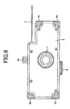
- Fig. 6 is a front view, as seen from the opening surface side of a speaker unit, of the bass reflex type speaker apparatus according to the present invention.
- Fig. 9 is a bottom view, as seen from bottom, of the bass reflex type speaker apparatus according to the present invention.
- Fig. 2 is a perspective view, as seen from the speaker opening side, of a bass reflex type speaker apparatus according to the present invention, showing the outline of a rectangular box speaker, an embodiment of the present invention.
- the speaker box of the present bass reflex type speaker apparatus is configured by integrating a woofer speaker unit 1 with front and back cabinets 2 and 3 having an opening, with both cabinets fixed to a front panel of a television receiver, etc. with mounting holes (4b to 4e) provided at four surrounding positions. Therefore, the back cabinet 3 serves also as a rear surface wall of the speaker box. It is to be noted that there is inserted into a mounting hole 4a, a boss for fixing front and back panels of the television receiver.
- 5 in Fig. 2 is a speaker connection connector.
- FIG. 3 6a to 6d are mounting holes of the speaker unit 1, 7 a bass reflex duct, 8 an external opening portion of the bass reflex duct 7, 9 an inner opening portion of the bass reflex duct 7, 10a a top surface portion of the back cabinet 3 and 10b a bottom surface portion of the back cabinet 3.
- the duct structure of the present embodiment is made up of two paths; a longer portion from a front end portion A-A' of the inner opening portion 9 to a bent portion B-B' and a shorter portion from the portion B-B' to a point D of a front end portion of the external opening portion 8 releasing sound.
- the position of the inner opening portion 9, one end of the longer portion is extended to near a corner portion of the speaker box, thus securing the duct's linear distance required for bass reflex effect.
- Fig. 5 is a partial sectional view showing, in a right-side view of the bass reflex type speaker apparatus according to the present invention, the speaker apparatus with a back cabinet 3 removed. As shown in Fig. 5, to make the speaker box thinner, the apparatus is disposed such that the direction shown by line E-E' in the same figure, i.e., an entire longitudinal linear portion of the bass reflex duct 7 is parallel with the front surface of the speaker box, i.e., the opening surface of the speaker unit 1.
- the bass reflex duct it is possible, by bending the bass reflex duct, by diagonally fixing and mounting the duct relative to a given wall surface of the speaker box and by arranging the longest longitudinal portion of the duct in parallel with the front surface of the speaker box (i.e., opening surface of the speaker unit) , to reduce the size, namely, height, width and depth of the speaker box incorporating the duct.
- the bass reflex duct is arranged near the speaker unit and displaced two-dimensionally from the direction of thickness of the speaker unit, to reduce the size, namely, height, width and depth of the speaker box incorporating the duct.
- the speaker box can be made more compact by having a duct provided with a plurality of bent portions.
- the external opening portion 8 of the duct 7 is provided on the bottom surface of the speaker box in the present embodiment, with the cross-section being oval as shown in the same figure. It is to be noted that the range of the oval cross-sectional portion in the present embodiment is the tapered portion in the duct's inner surface portion between C and D shown in Fig. 3.
- the bass reflex duct has an oval external opening surface, to reduce the depth of the speaker box, thus allowing thickness reduction.
- the duct located within the speaker box is cylindrical
- the above embodiment is not limited to cylindrical duct, and the same effect can be obtained by using an oval or box-shaped duct.
- the direction, in which the external opening portion 8 of the bass reflex duct 7 is provided, can be changed arbitrarily depending on the positions where mid/treble stereo speakers are installed that are used together with the woofer of the display device used, and may be radiated toward the wall surface of the speaker box other than the front and rear surfaces thereof such as the top surface side or the left and right wall surfaces of the speaker box.
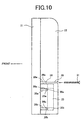
- Fig. 10 is a side view of a thin television receiver according to the present invention, with a speaker box mounted therein.
- Fig. 11 is a partial perspective view, as seen from rear, when the speaker box is mounted in the thin television receiver according to the present invention.
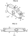
- Fig. 12 is a perspective view, as seen from front, of the speaker box applied to the present invention.
- Fig. 13 is a bottom view, as seen from bottom, of the speaker box applied to the present invention.
- 21 is a liquid crystal television receiver's front panel, 22 a back panel of the television receiver and 23 a speaker box, with the speaker box 23 having a front cabinet 23a and a back cabinet 23b. Further, the speaker box 23 has mounting portions 24, 25a, 25b, 25c and 25d that are provided projecting on the outer perimeter portion of the front cabinet 23a.
- 26a, 26b, 26c, 26d and 26e are, for example, vibration-insulating members made of cylindrical rubber members, with these members inserted from the notched portion side of each of the mounting portions 24, 25a, 25b, 25c and 25d and held.
- Each of 27a, 27b, 27c, 27d, 27e and 27f is a speaker box mounting hole for fixing the front and back cabinets 23a and 23b with screws (not shown).
- Each of 28a, 28b, 28c, 28d and 28e is a boss configured integrally with the front panel 21 of the television receiver on the rear surface side of the front panel 21 and provided projecting in the inner direction; 29 is a boss provided integrally with the back panel 22 on the rear surface side of the back panel 22 of the television receiver and projecting in the inner direction.
- 30a, 30b, 30c and 30d are each a screw for mounting and fixing the speaker box 23 to each of the bosses (28a, 28b, 28c, 28d) provided on the rear surface portion of the front panel 21 of the television receiver; 31 a screw for tightening together and fixing the back panel 22 of the television receiver to the boss 28e provided on the rear surface portion of the front panel 21 of the television receiver via the mounting portion 24 provided on the upper portion of the speaker box 23.
- 32 is a speaker unit mounted within the speaker box 23, and 33 a duct provided on the bottom surface portion of the speaker box 23.
- the woofer bass reflex type speaker unit 32 is mounted and fixed within the speaker box 23 by fixing members (not shown), with the opening thereof facing the front surface.
- the sound release duct 33 of the bass reflex type speaker as shown in Fig. 13.
- the duct 33 having an oval sound release port, plays a role of radiating a given frequency component downward of the television receiver's enclosure from the sound release port.
- the mounting configuration of the bass reflex type speaker box 23 will be described below in sequence.
- the speaker box 23 is a horizontal box-shaped speaker, and the front and back cabinets 23a and 23b of the speaker box 23 are joined by first adhering the joining portions of the two with a member such as adhesive and then tightening and fixing the mounting holes (27a to 27f) with a plurality of screws (not shown) from the rear surface portion of the back cabinet 23b, as shown in Fig. 11, thus enhancing hermetic properties of the two joining portions.
- the plurality of mounting portions 24 and 25a to 25d for mounting the speaker box 23 to the front panel 21 of the television receiver.
- the mounting portion 24 is provided on the upper portion, whereas the mounting portions 25a to 25d are each provided at a corner portion on the left or right side surface.
- the mounting portion 24 is, as shown in Fig. 12, provided projecting upward at the substantially horizontal center portion when viewed from the opening portion (front surface side) of the speaker box 23, with the mounting portion 24 shaped to have the front end portion notched in the shape of a depression and the depression-shaped portion hollowed out in a cylindrical manner in the direction of thickness as shown in Fig. 11.
- the mounting portion 24 has the vibration-insulating member 26e, made of a cylindrical elastic member having a hollow at the center (rubber bushing used in the present invention) shown in Fig. 11, inserted from the side surface and held and fixed in the depression-shaped notched portion as shown in Fig. 12.
- vibration-insulating members By providing, in a fixed manner, these vibration-insulating members in each mounting portion, vibrations of the speaker box 23 are suppressed from conducting to the enclosure of the television receiver. While in the present embodiment, rubber was used for the vibration-insulating members, for example, silicon rubber and other materials can be preferably used. The vibration-insulating members are not limited thereto, and other elastic materials such as spring, leaf spring and urethane may be used.
- these portions are provided in parallel with each other and on substantially the same plane, when viewed from the joining cross-section along a line X-X shown in Fig. 13, thus preventing the number of mounting vibration points of the speaker box 23 from increasing in the direction of depth of the speaker box 23 when the speaker box 23 is fixed to the front panel 21 of the television receiver.
- the surface is fastened first by applying adhesive, and then the back cabinet 23b is fixed to the front cabinet 23a with screws (not shown), thus enhancing hermetic properties, preventing vibrations and enhancing the acoustic characteristic of the speaker box 23.
- the speaker box 23 used in the present invention is a phase inverted type bass reflex speaker box incorporating the woofer speaker unit 32, with the duct that determines the acoustic characteristic thereof provided within the box.
- a bass reflex speaker box is mounted within the enclosure of a thin television receiver, it is of extreme importance, in order to suppress vibrations of the speaker and the receiver's main body, in which direction of the enclosure of the television receiver the sound release port of the external duct of the speaker box is provided.
- the sound release port of the duct is provided on the bottom surface portion of the speaker box 23, that is, on the external wall surface of the speaker box 23 oriented vertically in a different direction from the opening surface or the rear surface of the speaker unit 32, sound is externally released in the present embodiment from the bottom surface of the television receiver's enclosure as shown in Fig. 13.
- the duct's sound release port may be provided on the upper surface wall of the speaker box 23, if, for example, the speaker box 23 is provided on the upper portion of the enclosure of the television receiver, and alternatively the duct's sound release port may be provided on the side surface wall of the speaker box 23 if the speaker box 23 is provided on the left or right side surface of the enclosure of the television receiver. That is, the position where the sound release duct is provided on the speaker box 23 can be arbitrarily selected depending on the shape of the television receiver's enclosure and the mounting position of the speaker box.
- the single mounting portion provided on the top surface portion on the outer perimeter of the front cabinet of the speaker box, is fixed only to the back panel of the television receiver, thus resulting in the back panel suspending the speaker box from above at one point with the single mounting portion.
- the back panel of the television receiver's enclosure is fixed only at one point to the front panel of the television receiver's enclosure via the speaker box, thus allowing reduction of the number of bosses, necessary for mounting the speaker box and provided on the enclosure of the television receiver, and labor cost.
- the vibration-insulating members (26a, 26b, 26c, 26d, 26e), held in the depressed portions provided in the mounting portions 24 and 25a to 25d of the speaker box 23, are inserted onto the bosses (28a to 28e) provided on the front panel 21 of the television receiver.
- the speaker box 23 is mounted and fixed to the front panel 21 via the mounting portions 25a to 25d and the bosses (28a to 28e) using the screws (30a, 30b, 30c, 30d). In this condition, therefore, only the mounting portion 24 provided on the upper portion of the speaker box 23 is not fixed.
- the back panel 22 of the television receiver is pressed and fixed to the front panel 21 using a plurality of mounting screws (not shown).
- the boss 29 for fixing the speaker box 23 and that is hollowed out.
- the boss 29 of the back panel 22, the mounting portion 24 of the speaker box 23 and the boss 28e of the front panel 21 of the television receiver are pressed and fixed with the mounting screw 31 from the rear surface of the back panel 22 of the television receiver.
- each of the mounting portions provided on the outer perimeter of the speaker box 23 are fixed to the front panel 21 of the television receiver via the bosses alone.
- the single mounting portion 24, provided on the top surface portion of the speaker box 23 tightens together and fixes both the front and back panels 21 and 22 of the television receiver via the bosses, thus fixing the speaker box 23 by suspending the speaker box 23 at one fixed fulcrum using both the front and back cabinets of the television receiver.
- the speaker apparatus according to the present invention while being not only compact and lightweight but also thin, is applicable to a bass reflex type speaker apparatus having excellent bass characteristic.
- a bass reflex type speaker apparatus is incorporated in a television receiver equipped with a thin display device such as liquid crystal display device (LCD) or plasma display device (PDP)
- LCD liquid crystal display device
- PDP plasma display device
Landscapes
- Engineering & Computer Science (AREA)
- Signal Processing (AREA)
- Physics & Mathematics (AREA)
- Acoustics & Sound (AREA)
- Multimedia (AREA)
- Health & Medical Sciences (AREA)
- Otolaryngology (AREA)
- Details Of Audible-Bandwidth Transducers (AREA)
Abstract
Description
Claims (16)
- A bass reflex type speaker apparatus comprising a speaker box having an opening portion on a front surface, a speaker unit mounted within the speaker box in conformity with the opening portion, and a tubular duct that externally radiates sound from a rear surface of the speaker unit disposed within the speaker box through phase inversion, wherein the duct has on the same plane one or a plurality of bent portions bent in substantially dogleg form and linear portions extending at both ends of the bent portion, and wherein the duct is disposed in parallel with the front surface of the speaker box.
- The bass reflex type speaker apparatus as defined in claim 1, wherein at least the longest linear portion of the linear portions is disposed tilted relative to one or more wall surfaces except for the front and rear surfaces of the speaker box.
- The bass reflex type speaker apparatus as defined in claim 1, wherein the speaker box has a second opening portion for externally projecting one of the linear portions extended from the bent portion of the duct, and wherein the bent portion is disposed in the vicinity of the second opening portion of the speaker box.
- The bass reflex type speaker apparatus as defined in claim 1, wherein the duct is disposed at a position where the duct does not overlap the speaker unit as seen two-dimensionally from the front surface of the speaker box.
- The bass reflex type speaker apparatus as defined in claim 1, wherein an inner surface at a front end of the linear portion of the duct projected externally from the second opening portion is spread in tapered form near the second opening portion of the speaker box.
- The bass reflex type speaker apparatus as defined in any one of claims 3 to 5, wherein the opening surface of the duct projected from the second opening portion is oval.
- The bass reflex type speaker apparatus as defined in any one of claims 3 to 5, wherein the length of the linear portion projected externally from the second opening portion outside the speaker box is shorter than that of the other linear portion extended internally from the bent portion into the speaker box.
- The bass reflex type speaker apparatus as defined in any one of claims 3 to 5, wherein the speaker box has the second opening portion on a wall surface other than the front and rear surfaces of the speaker box.
- A speaker apparatus mounting structure for mounting and fixing a speaker apparatus with a substantially box-shaped speaker box within an enclosure of a television receiver having front and back panels, wherein the speaker apparatus is provided with a plurality of first mounting portions for clamping and retaining vibration-insulating members at any plurality of corner portions of all the corner portions of the speaker box and with a second mounting portion that projects upward at a substantially center position on an upper portion of a top surface of the speaker box, the second mounting portion clamping and retaining at least one vibration-insulating member, the first and second mounting portions being disposed integrally with the speaker box, and wherein the vibration-insulating members of the first mounting portions are secured to mounting members provided on the front panel of the television receiver, the vibration-insulating member of the second mounting portion being clamped between the front and back panels by clamping members on the front and back panels of the television receiver such that the clamped vibration-insulating member and the clamping members are tightened together and fixed.
- The speaker apparatus mounting structure as defined in claim 9, wherein the speaker box is made up of front and back cabinets, and wherein the first and second mounting portions are disposed in parallel and on substantially the same plane when viewed from a cross-section joining the front and back cabinets of the speaker box.
- The speaker apparatus mounting structure as defined in claim 9, wherein the first and second mounting portions are depression-shaped so as to be open upward when viewed from the front or back cabinet.
- The speaker apparatus mounting structure as defined in claim 9, wherein the vibration-insulating member of the second mounting portion is clamped by bosses provided on the front and back panels of the television receiver, each boss projecting inward, and wherein, by fixing the clamped vibration-insulating member and each of the bosses with fixing members, the speaker apparatus is mounted such that at least one point of the speaker apparatus is suspended by the front and back panels of the television receiver.
- The speaker apparatus mounting structure as defined in claim 9, wherein the vibration-insulating members are cylindrical elastic bodies.
- The speaker apparatus mounting structure as defined in any one of claims 9 to 13, wherein the speaker apparatus is a bass reflex type speaker apparatus incorporating at least one speaker unit.
- The speaker apparatus mounting structure as defined in claim 14, wherein the speaker apparatus has a tubular duct for externally radiating sound from a rear surface of the speaker unit through phase inversion, and wherein a sound release surface of the duct is disposed on a wall surface other than the front and rear surfaces of the speaker box.
- A speaker apparatus mounting method for mounting and fixing a speaker apparatus with a substantially box-shaped speaker box within an enclosure of a television receiver having front and back panels, the method comprising clamping and retaining vibration-insulating members by first mounting portions disposed at any plurality of corner portions of all the corner portions of the speaker box; clamping and retaining at least one vibration-insulating member by a second mounting portion projecting upward at a substantially center position on an upper portion of a top surface of the speaker box; securing the vibration-insulating members of the first mounting portions to mounting members provided on the front panel of the television receiver; and clamping the vibration-insulating member of the second mounting portion between the front and back panels by clamping members on the front and back panels of the television receiver such that the clamped vibration-insulating member and the clamping members are tightened together and fixed.
Applications Claiming Priority (5)
| Application Number | Priority Date | Filing Date | Title |
|---|---|---|---|
| JP2002071349 | 2002-03-15 | ||
| JP2002071349A JP3816016B2 (en) | 2002-03-15 | 2002-03-15 | Bass reflex type speaker device |
| JP2002336509 | 2002-11-20 | ||
| JP2002336509 | 2002-11-20 | ||
| PCT/JP2003/002526 WO2003079719A1 (en) | 2002-03-15 | 2003-03-04 | Bass reflex type speaker device, mounting structure and mounting method for speaker device |
Publications (2)
| Publication Number | Publication Date |
|---|---|
| EP1487234A1 true EP1487234A1 (en) | 2004-12-15 |
| EP1487234A4 EP1487234A4 (en) | 2005-12-07 |
Family
ID=28043718
Family Applications (1)
| Application Number | Title | Priority Date | Filing Date |
|---|---|---|---|
| EP03707206A Withdrawn EP1487234A4 (en) | 2002-03-15 | 2003-03-04 | Bass reflex type speaker device, mounting structure and mounting method for speaker device |
Country Status (7)
| Country | Link |
|---|---|
| US (1) | US7184566B2 (en) |
| EP (1) | EP1487234A4 (en) |
| KR (1) | KR100609796B1 (en) |
| CN (1) | CN100592822C (en) |
| AU (1) | AU2003211513A1 (en) |
| TW (1) | TWI227647B (en) |
| WO (1) | WO2003079719A1 (en) |
Cited By (2)
| Publication number | Priority date | Publication date | Assignee | Title |
|---|---|---|---|---|
| EP1773092A2 (en) * | 2005-10-04 | 2007-04-11 | Gealan Formteile GmbH | Enclosure with sealing arrangement |
| CN104168525A (en) * | 2014-07-25 | 2014-11-26 | 无锡杰夫电声有限公司 | Inverted phase type multipoint excitation loudspeaker case |
Families Citing this family (14)
| Publication number | Priority date | Publication date | Assignee | Title |
|---|---|---|---|---|
| JP2005268868A (en) * | 2004-03-16 | 2005-09-29 | Orion Denki Kk | Television receiver with reinforcing mounting structure |
| TWI273857B (en) * | 2005-09-29 | 2007-02-11 | Asustek Comp Inc | Speaker with vibration-proof design |
| CN100499971C (en) * | 2005-11-04 | 2009-06-10 | 群康科技(深圳)有限公司 | Panel display |
| JP5110012B2 (en) | 2008-03-27 | 2012-12-26 | ヤマハ株式会社 | Speaker device |
| JP5979355B2 (en) * | 2012-06-07 | 2016-08-24 | ヤマハ株式会社 | Speaker device and speaker box |
| KR101675157B1 (en) | 2015-04-24 | 2016-11-22 | 주식회사 비젼테크닉스 | Speaker Unit with Amp |
| WO2017003412A1 (en) * | 2015-06-27 | 2017-01-05 | Intel Corporation | Attachment for devices |
| US10645241B2 (en) * | 2017-09-26 | 2020-05-05 | Fuji Xerox Co., Ltd. | Sound emitting device, image forming apparatus and electronic apparatus |
| CN107959908A (en) * | 2017-11-22 | 2018-04-24 | 江苏鹏美电声器材有限公司 | A kind of speaker |
| CN213906836U (en) * | 2020-11-30 | 2021-08-06 | 瑞声光电科技(常州)有限公司 | Speaker boxes and electronic equipment |
| JP2022119087A (en) * | 2021-02-03 | 2022-08-16 | 船井電機株式会社 | Display device and speaker unit |
| CN112929770A (en) * | 2021-02-05 | 2021-06-08 | 歌尔科技有限公司 | Sound cavity structure and sound box |
| US12382216B2 (en) * | 2023-04-19 | 2025-08-05 | Dell Products L.P. | Embedded damper speaker design |
| KR102721548B1 (en) * | 2023-04-28 | 2024-10-23 | 엘지전자 주식회사 | Sound device and display device including it |
Family Cites Families (21)
| Publication number | Priority date | Publication date | Assignee | Title |
|---|---|---|---|---|
| GB8425657D0 (en) | 1984-10-10 | 1984-11-14 | Austin Rover Group | Exhaust system |
| JPS6339520A (en) | 1986-08-02 | 1988-02-20 | 原科 利行 | Seedling growing method and mat |
| JPS6387979A (en) | 1986-10-02 | 1988-04-19 | Tax Adm Agency | Immobilization of biocatalyst |
| JPH0644229Y2 (en) * | 1986-11-27 | 1994-11-14 | ソニー株式会社 | Speaker device |
| JPS64889A (en) | 1987-06-23 | 1989-01-05 | Matsushita Electric Ind Co Ltd | Speaker system for television |
| JPH0830967B2 (en) | 1987-10-07 | 1996-03-27 | 横河電機株式会社 | Self tuning controller |
| JPH01143587U (en) * | 1988-03-25 | 1989-10-02 | ||
| JP2501682Y2 (en) * | 1989-08-15 | 1996-06-19 | ヤマハ株式会社 | Spoker case open pipe port mounting structure |
| US5111905A (en) * | 1989-11-30 | 1992-05-12 | Rogersound Labs, Inc. | Speaker enclosure |
| JPH04114598A (en) | 1990-09-04 | 1992-04-15 | Sharp Corp | Bass reflex type speaker system |
| US5147986A (en) * | 1990-12-03 | 1992-09-15 | Tandy Corporation | Subwoofer speaker system |
| US5361380A (en) * | 1991-06-19 | 1994-11-01 | Daewoo Electronics Co., Ltd. | Woofer module for use in a television set |
| KR0183670B1 (en) * | 1992-07-14 | 1999-05-15 | 강진구 | Speaker system |
| JPH06217385A (en) | 1993-01-14 | 1994-08-05 | Sony Corp | Bass reflex speaker box |
| US5400408A (en) * | 1993-06-23 | 1995-03-21 | Apple Computer, Inc. | High performance stereo sound enclosure for computer visual display monitor and method for construction |
| JPH07177443A (en) | 1993-12-16 | 1995-07-14 | Toshiba Corp | Speaker set speaker system |
| JPH08336194A (en) | 1995-06-07 | 1996-12-17 | Sanyo Electric Co Ltd | Speaker box mounting structure |
| JPH0965251A (en) | 1995-08-28 | 1997-03-07 | Matsushita Electric Ind Co Ltd | Screen shake prevention device |
| US5844176A (en) * | 1996-09-19 | 1998-12-01 | Clark; Steven | Speaker enclosure having parallel porting channels for mid-range and bass speakers |
| KR100327357B1 (en) | 1999-04-16 | 2002-03-06 | 구자홍 | speaker system in video display appliance |
| JP2001145186A (en) | 1999-11-12 | 2001-05-25 | Matsushita Electric Ind Co Ltd | Television receiver |
-
2003
- 2003-03-04 AU AU2003211513A patent/AU2003211513A1/en not_active Abandoned
- 2003-03-04 EP EP03707206A patent/EP1487234A4/en not_active Withdrawn
- 2003-03-04 CN CN03810925A patent/CN100592822C/en not_active Expired - Fee Related
- 2003-03-04 US US10/507,629 patent/US7184566B2/en not_active Expired - Fee Related
- 2003-03-04 WO PCT/JP2003/002526 patent/WO2003079719A1/en not_active Ceased
- 2003-03-04 KR KR1020047014404A patent/KR100609796B1/en not_active Expired - Fee Related
- 2003-03-14 TW TW092105632A patent/TWI227647B/en not_active IP Right Cessation
Cited By (2)
| Publication number | Priority date | Publication date | Assignee | Title |
|---|---|---|---|---|
| EP1773092A2 (en) * | 2005-10-04 | 2007-04-11 | Gealan Formteile GmbH | Enclosure with sealing arrangement |
| CN104168525A (en) * | 2014-07-25 | 2014-11-26 | 无锡杰夫电声有限公司 | Inverted phase type multipoint excitation loudspeaker case |
Also Published As
| Publication number | Publication date |
|---|---|
| US7184566B2 (en) | 2007-02-27 |
| WO2003079719A1 (en) | 2003-09-25 |
| US20050117768A1 (en) | 2005-06-02 |
| TWI227647B (en) | 2005-02-01 |
| TW200401576A (en) | 2004-01-16 |
| KR100609796B1 (en) | 2006-08-08 |
| CN1653848A (en) | 2005-08-10 |
| CN100592822C (en) | 2010-02-24 |
| EP1487234A4 (en) | 2005-12-07 |
| AU2003211513A1 (en) | 2003-09-29 |
| KR20040091136A (en) | 2004-10-27 |
Similar Documents
| Publication | Publication Date | Title |
|---|---|---|
| US7184566B2 (en) | Bass reflex type speaker device, mounting structure and mounting method for speaker device | |
| EP2282553B1 (en) | Bass sound amplifying enclosure, woofer including the same, and electronic device including the woofer | |
| JP4808168B2 (en) | Display device | |
| US20100111343A1 (en) | Display with miniature speaker and the structure of the miniature speaker | |
| CN113994712B (en) | display screen | |
| US4408678A (en) | Loudspeaker enclosure | |
| EP2182736A1 (en) | Miniature speaker and display with miniature speaker | |
| JP2011160319A (en) | Acoustic device and display device | |
| JP3998618B2 (en) | Display device | |
| CN1117339A (en) | speaker system | |
| JP3995632B2 (en) | Bass reflex speaker device and video display device incorporating the bass reflex speaker device | |
| JPH11122560A (en) | Television receiver with speaker vibration preventing device | |
| AU691750B2 (en) | Howling phenomena removing apparatus for video display apparatus | |
| US7302075B2 (en) | Electronic device with loudspeaker | |
| JP4059272B2 (en) | Speaker system and speaker enclosure | |
| US20070206828A1 (en) | Distributed acoustic cabinet | |
| JP3957281B2 (en) | A stand with speakers | |
| JP3816016B2 (en) | Bass reflex type speaker device | |
| KR100732167B1 (en) | Speaker assembly and video equipment | |
| JP2018129685A (en) | Display unit and television receiver | |
| JP2018129686A (en) | Woofer box, display device, and television receiver | |
| JPH10191486A (en) | Speaker system and display device using the same | |
| JP2007067462A (en) | Speaker mounting structure | |
| JP2011077851A (en) | Stand and display device |
Legal Events
| Date | Code | Title | Description |
|---|---|---|---|
| PUAI | Public reference made under article 153(3) epc to a published international application that has entered the european phase |
Free format text: ORIGINAL CODE: 0009012 |
|
| 17P | Request for examination filed |
Effective date: 20040917 |
|
| AK | Designated contracting states |
Kind code of ref document: A1 Designated state(s): AT BE BG CH CY CZ DE DK EE ES FI FR GB GR HU IE IT LI LU MC NL PT RO SE SI SK TR |
|
| AX | Request for extension of the european patent |
Extension state: AL LT LV MK RO |
|
| A4 | Supplementary search report drawn up and despatched |
Effective date: 20051024 |
|
| 17Q | First examination report despatched |
Effective date: 20070814 |
|
| GRAP | Despatch of communication of intention to grant a patent |
Free format text: ORIGINAL CODE: EPIDOSNIGR1 |
|
| INTG | Intention to grant announced |
Effective date: 20140714 |
|
| STAA | Information on the status of an ep patent application or granted ep patent |
Free format text: STATUS: THE APPLICATION IS DEEMED TO BE WITHDRAWN |
|
| 18D | Application deemed to be withdrawn |
Effective date: 20141125 |