TECHNICAL FIELD
The present invention relates to a format secondary
conversion method for an image signal, and a method and an
apparatus for transmitting a time code signal used for the format
secondary conversion method for the image signal.
BACKGROUND OF THE INVENTION
As a time code signal used for transmitting an image signal,
LTC (Linear Time Code) signal subjected to a Biphasemark
modulation and recorded in an audio frequency band can be
mentioned. The time code signal is transmitted in a synchronous
state with respect to the image signal.
The advancement in an image technology in recent years
has realized a format conversion of the image signal. In general,
when the format conversion is executed, the number of frames
per second is increased or decreased. More specifically, the
format conversion processing results in increasing or
decreasing the number of image data (hereinafter, referred to
as frame image data) per second constituting the respective
frames in the image signal. Therefore, at least one frame image
data of the respective frame image data constituting the image
signal prior to the conversion is consequently eliminated or
written in an overlapping state in the converted image signal.
When the format conversion is executed to the image signal,
the image signal is inversely converted into a format prior
to the conversion as circumstances demand. Hereinafter, the
initial format conversion is called a primary conversion, and
the format conversion for inverting the primary-converted image
signal into the original image signal is called a secondary
conversion.
In order to accurately secondary-convert the
primary-converted image signal into the original image signal,
it becomes necessary that the respective frames in the
primary-converted image signal and the respective frames in
the secondary-converted image signal accurately correspond to
each other. In order to make them accurately correspond to
each other, it is important to accurately grasp a frame position
where any change is generated in the image data in the
primary-converted image signal at the time of executing the
secondary conversion (inverse conversion).
However, a conventional technology has neither
established any configuration where a relationship between the
frame position and the time code signal can be accurately grasped
nor proposed any effective method in the time code signal
corresponding to the primary-converted image signal.
Therefore, a main object of the present invention is to
accurately grasp the relationship between the frame position
and the time code signal in the image signal, which is subjected
to the time of the primary conversion, to thereby accurately
execute the format secondary conversion to the image signal.
DISCLOSURE OF THE INVENTION
In order to accomplish the foregoing object, a first time
code signal transmission method according to the present
invention is a time code signal transmission method for
transmitting a time code signal corresponding to an image signal
after a format conversion, in which the number of frames per
second is changed, is executed thereto, wherein information
indicating a frame position in the image signal, where image
data is changed through the format conversion, is attached to
the time code signal to be transmitted.
A first time code signal transmission apparatus according
to the present invention is a time code signal transmission
apparatus for transmitting the time code signal corresponding
to the image signal after the format conversion, in which the
number of frames per second is changed, is executed thereto,
comprises a creation device, the creation device creating the
information indicating the frame position in the image signal
where the image data is changed through the format conversion,
and an attachment device, the attachment device attaching the
information to the time code signal to be transmitted.
A second time code signal transmission method according
to the present invention is a time code signal transmission
method for transmitting a time code signal corresponding to
an image signal after a format conversion, in which the number
of frames per second is changed, is executed thereto, wherein
information indicating a synchronous state between frame
conversion cycles in the format conversion and time code
progression is attached to the time code signal to be
transmitted.
A second time code signal transmission apparatus
according to the present invention is a time code signal
transmission apparatus for transmitting a time code signal
corresponding to the image signal after the format conversion,
in which the number of frames per second is changed, is executed
thereto, comprises a creation device, the creation device
creating the information indicating the synchronous state
between the frame conversion cycles in the format conversion
and the time code progression and an attachment device, the
attachment device attaching the information to the time code
signal to be transmitted in response to the time code
progression.
A first format secondary conversion method for image
signal according to the present invention is a format secondary
conversion method for image signal for restituting the image
signal after a format primary conversion, in which the number
of frames per second is changed, is executed thereto through
a secondary conversion (inverse conversion) to the image signal
of an original format, wherein the information indicating the
frame position in the primary-converted image signal, in which
the image data is changed through the format primary conversion,
is attached to the time code signal corresponding to the image
signal after the format primary conversion, the information
indicating the frame position is retrieved from the time code
signal when the primary-converted image signal is subjected
to the secondary conversion, and the primary-converted image
signal is secondary-converted into the image signal of the
original format based on the retrieved information.
A second format secondary conversion method for image
signal according to the present invention is a format secondary
conversion method for image signal for restituting the image
signal after a format primary conversion, in which the number
of frames per second is changed, is executed thereto through
a secondary conversion (inverse conversion) to the image signal
of an original format, wherein the information indicating the
synchronous state between the frame conversion cycles in the
format conversion and the time code progression is attached
to the time code signal corresponding to the image signal after
the format primary conversion, the information indicating the
synchronous state is retrieved from the time code signal when
the primary-converted image signal is subjected to the secondary
conversion, and the primary-converted image signal is
secondary-converted into the image signal of the original format
based on the retrieved information.
Accordingly, in the present invention, the secondary
conversion can be executed with the accurate knowledge of the
relationship between the frame position and the time code in
the format secondary conversion of the image signal.
In the first time code signal transmission method, first
time code signal transmission apparatus, and first format
secondary conversion method for image signal according to the
present invention, the information preferably represents a
fieldposition in the image signal where the image data is changed
in the format conversion. In that manner, the secondary
conversion can be executed while exactly knowing the
relationship between the field position and the time code, and
by extension, mutual conversions (primary and secondary
conversions) between an interlace image signal and a progressive
image signal can be executed with a high accuracy.
The information is preferably attached to a user' s bit
area of the time code signal.
BRIEF DESCRIPTION OF THE DRAWINGS
Fig. 1 is a block diagram illustrating a configuration
of a time code signal transmission apparatus according to a
preferred embodiment of the present invention.
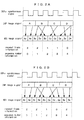
Fig. 2A and 2B are frame formats illustrating a format
conversion, in which a 24P image signal is converted into a
60I image signal.
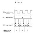
Fig. 3 is a frame format illustrating a format conversion,
in which a 10P image signal is converted into the 60I image
signal
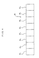
Fig. 4 is a frame format illustrating a configuration
of a user' s bit area of a time code signal (LTC signal) used
in the present invention.
DESCRIPTION OF THE PREFERRED EMBODIMENT
Hereinafter, a preferred embodiment of the present
invention is described referring to the drawings. Fig. 1 is
a block diagram illustrating a configuration of a time code
signal transmission apparatus according to a preferred
embodiment of the present invention. The present embodiment
is premised on a format conversion of an image signal. In the
present embodiment, the invention is realized by means of an
apparatus for transmitting a time code signal corresponding
to the format-converted image signal. To be more specific,
the present embodiment is premised on a primary conversion of
an image signal (hereinafter, referred to as 24P image signal)
in a progressive format of 24 frames/second (hereinafter,
referred to as 24P format) into an image signal (hereinafter,
referred to as 60I image signal) in an interlace format of 30
frames/second (hereinafter, referred to as 60I format).
In the present embodiment, the invention is realized by
means of a time code signal transmission apparatus 1 for
transmitting the time code signal corresponding to the converted
image signal (60I image signal) in executing the format primary
conversion and a format secondary conversion (inverse
conversion) using the transmitted time code.
The time code signal transmission apparatus 1 comprises
a transmission unit 2 and a reception unit 3. A configuration
of the transmission unit 2 is first described.
The transmission unit 2 comprises a time code information
reading device 4, a renewal frame information creation device
5, a time code auxiliary information creation device 6, a
sequence number information creation device 7, a transmission
side verification data creation device 9, an LTC signal creation
device 10, and a transmission device 11.
The time code information reading device 4 reads time
code information It created outside of the time code signal
transmission apparatus 1. The time code information reading
device 4 outputs the read time code information It to the renewal
frame information creation device 5, time code auxiliary
information creation device 6, sequence number information
creation device 7, and LTC signal creation device 10.
The renewal frame information creation device 5, time
code auxiliary information creation device 6, and sequence
number information creation device 7 create different kinds
of attached information Ia from the time code information It
readby the time code information reading device 4. The attached
information Ia is to be stored in a user' s bit area 20 of the
LTC signal (time code signal).
The attached information Ia includes renewal frame
information Ib, time code auxiliary information Ic, and sequence
number information Id. The renewal frame information Ib is
created in the renewal frame information creation device 5.
The time code auxiliary information Ic includes frame rate
information (numeral value information of frame rate) Ic1,
interlace/progressive discrimination information Ic2, and
other auxiliary information Ic3. The time code auxiliary
information Ic including such information is created in the
time code auxiliary information creation device 6. The
sequence number information Id is created in the sequence number
information creation device 7.
The creation devices 5, 6 and 7 output the different kinds
of attached information Ia created thereby to the LTC signal
creation device 10 and transmission side verification data
creation device 9.
The transmission side verification data creation device
9 creates transmission side verification data Dt from the
attached information Ia (renewal frame information Ib, time
code auxiliary information Ic, and sequence number information
Id) inputted therein, and outputs the transmission side
verification data Dt to the LTC signal creation device 10. To
put it differently, the transmission side verification data
creation device 9 uses the attached information Ia inputted
therein as the information to be verified to thereby create
the transmission side verification data Dt.
The LTC signal creation device 10 creates the LTC signal,
which is the time code signal, based on the time code information
It, attached information Ia (renewal frame information Ib, time
code auxiliary information Ic, and sequence number information
Id) , and transmission side verification data Dt. The LTC signal
creation device 10 outputs the created LTC signal to the
transmission device 11. The transmission device 11 transmits
the inputted LTC signal to the reception unit 3, in which the
transmission method is not particularly limited. The
transmission device 11 transmits the LTC signal to the reception
unit 3 by means of, for example, cable transmission.
Next, a configuration of the reception unit 3 is described.
The reception unit 3 comprises a reception device 12, an
information-to-be-verified reading device 13, a reception side
verification data creation device 14, a verification data
reading device 15, and a verification device 16.
The reception device 12 receives the LTC signal
transmitted from the transmission unit 2. The
information-to-be-verified reception-side reading device 13
reads the attached information Ia from the user' s bit area 20
of the received LTC signal, and outputs the attached information
Ia to the reception side verification data creation device 14.
The reception side verification data creation device 14
executes a calculation processing using the read attached
information Ia based on a predetermined verification formula
to thereby create a reception side verification data Dr. The
formula used in the reception side verification data creation
device 14 employs a verification formula used in the
transmission side verification data creation device 9.
The verification data reading device 15 reads the
transmission side verification data Dt from the received LTC
signal. The verification device 16 collates the transmission
side verification data Dt and the reception side verification
data Dr to thereby verify if any error is generated in the
information in the user' s bit area 20 of the received LTC signal.
A reference numeral 17 denotes an LTC signal output
terminal serving to output the LTC signal received by the
reception device 12 outside from the reception unit 3. A
reference numeral 18 denotes a verification result output
terminal serving to output the verification result of the
verification device 16 outside from the reception unit 3.
In the present embodiment, the renewal frame information
creation device 5 constitutes an example of a creation device,
the creation device creating information indicating a frame
position in the image signal where image data is changed in
the format conversion. The sequence number information
creation device 7 constitutes an example of a creation device,
the creation device creating information indicating a
synchronous state between frame conversion cycles and time code
progression in the format conversion. The LTC signal creation
device 10 constitutes an example of an attachment device.
However, the configuration examples are only part of
examples realizing the present invention. The present
invention can accept any configuration capable of exerting
functions recited in claims.
Next, the attached information Ia is described. The
attached information Ia is effective in the following
transmission form of the time code signal.
The advancement in an image technology in recent years
has realized the format conversion of the image signal. For
example, the image signal of the 24P format can be converted
into the image signal of the 60I format. In general, the
execution of the format conversion increases or decreases the
number of the frames per second. More specifically, the format
conversion processing increases or decreases the number of the
image data (hereinafter, referred to as frame image data) per
second constituting the respective frames in the image signal.
Therefore, at least one frame image data of the respective frame
image data consti tuting the image signal prior to the conversion
is consequently eliminated or written in an overlapping state
in the converted image signal.
When the format conversion is executed to the image signal
as described, the image signal is inversely converted into the
image signal of the format prior to the conversion whenever
necessary, a reason for which is mentioned below.
Many of image processing apparatuses generally used, such
as a nonlinear edition device, can only execute an image
processing of a standard format (for example, 60I format or
30P format). Because of that, when the image signal of the
standard format (for example, 60I format or 30P format) is
converted into the image signal of a non-standard format, it
becomes necessary to inversely convert the image signal into
the image signal of the standard format in order to execute
the image processing to the image signal by means of the general
image processing apparatus.
Further, when the image processing (nonlinear edition)
is executed to the image signal converted into the format
increasing the number of frames per second, it is effective
to inversely convert the image signal into the image signal
of the format prior to the conversion for such a reason that
the edition of the pre-conversion image format requires a less
memory capacity.
In the following description, the inverse conversion is
called the secondary conversion and discriminated from the
primary conversion initially executed. The image data is
comprised of the frame image data sequentially disposed in a
chronological order. In the case of an interlace image signal,
the frame image data is comprised of a pair of field image data.
In order to accurately restitute the primary-converted
image signal (hereinafter, referred to as primary conversion
image signal) to the original image signal through the secondary
conversion, it is necessary to accurately grasp an arrangement
order of the image data in the primary conversion image signal,
a reason for which is described below. The reason is described
exemplifying the conversion form where the 24P image signal
is primary-converted into the 60I image signal and the
conversion form where the 10P image signal is primary-converted
into the 60I image signal. Needless to say, the reason is applied
to the format conversion in other forms.
Fig. 2A and Fig. 2B illustrate the conversion form where
the 24P image signal is primary-converted into the 60I image
signal. Fig. 3 illustrates the conversion form where the 10P
image signal is primary-converted into the 60I image signal.
First, the primary conversion of the 24P image signal
into the 60I image signal is described referring to Fig. 2A.
Fig. 2A shows a conversion method called a 2:3:2:3 pull-down
method. 24P frame image data for four frames temporally
consecutive in the 24P image signal is converted into 60I frame
image data for five frames, which are increased by one frame
through the primary conversion into the 60I image signal.
When the primary conversion (24P → 60I) is executed by
means of the 2:3:2:3 pull-down conversion method to the image
signals having the format-wise differences, the processing is
as follows.
First, 24I frame image data (Ao|Ae), (Bo|Be), (Co|Ce),
and (Do|De) in a 24I image signal (interlace image signal
of 24 frames/second) is retrieved from the frame image data
(A), (B), (C), and (D) sequentially disposed on a time axis
in the 24P image signal. A symbol o denotes a first field.
A symbol e denotes a second field.
Further, the 60I frame image data (Ao|Ae), (Bo|Be),
(Bo|Ce), (Co|De), and (Do|De) for five frames in the 60I image
signal are created from the retrieved 24I frame image data
(Ao|Ae), (Bo|Be), (Co|Ce), and (Do|De). Such a creation
(conversion) process is repeated per four frames of the 24P
format to thereby primary-convert the 24P image signal into
the 60I image signal.
At that time, of the respective 24I field image data
(Ao), (Ae) , (Bo) , (Be) , (Co), (Ce) , (Do) , and (De)
constituting the retrieved 24I frame image data (Ao|Ae),
(Bo|Be), (Co|Ce), and (Do|De), two 24I field image data (Bo)
and (De), which makes one frame in sum total, are redundantly
used. The 24I field image data (Bo) and (De) to be redundantly
used and insertion positions thereof are determined in advance.
Further, arrangement positions of the respective 24I field
image data (Ao) , (Ae) , (Bo), (Be) , (Co) , (Ce), (Do), and (De)
including the 24I field image data (Bo) and (De) redundantly
used are also determined in advance. In Fig. 2A, theinsertion
and arrangement order is shown. Hereinafter, such a
rearrangement order in the primary conversion is called a
primary conversion order.
The conversion method called the 2:3:2:3 pull-down
conversion method was described referring to Fig. 2A. There
is another conversion method called a 2:3:3:2 pull-down
conversion method, as shown in Fig. 2B, that can be employed
when the 24P image signal is primary-converted into the 60I
image signal. In the 2:3:3:2 pull-down conversion method,
two 24I field image data (Bo) and (Ce) are redundantly used.
The 24I field image data (Bo) and (Ce) redundantly used and
insertion positions thereof are determined in advance.
Further, arrangement positions of the respective 24I field
image data (Ao), (Ae), (Bo), (Be), (Co) , (Ce) , (Do) , and (De)
including the 24I field image data (Bo) and (Ce) redundantly
used are determined in advance. In Fig. 2B, the insertion
and arrangement order is shown. As shown in Fig. 2B, the
2:3:3:2 pull-down conversion method is only slightly
different to the 2:3:2:3 pull-down conversion method in the
field combinations at the time of the conversion.
Next, the primary conversion of the 10P image signal into
the 60I image signal is described. 10I frame image data for
one frame in the 10P image signal is converted into the 60I
frame image data for three frames, which are increased by two
frames through the primary conversion into the 60I image signal.
To be specific, first, frame image data (Ao|Ae) in the
10I image signal (interlace image signal of ten frames/second)
is retrieved from respective 10P frame image data (A) in the
10P image signal.
Further, the 60I frame image data (Ao|Ae), (Ao|Ae), and
(Ao|Ae) for three frames in the 60I image signal are created
from the retrieved 10I frame image data (Ao|Ae). To be
specific, the 60I frame image data (Ao|Ae), (Ao|Ae), and
(Ao|Ae) for three frames are created by repeatedly copying
the same 10I frame image data (Ao|Ae) for three frames. Such
a creation (conversion) process is repeated per frame of the
10P format to thereby primary-convert the 10P image signal
into the 60I image signal. Fig. 3 shows the insertion and
arrangement order.
In order to accurately secondary-convert the various
primary conversion image signals described above into the
original image signals, it is necessary that the respective
frames in the primary conversion image signal and the respective
frames in the secondary-converted image signal accurately
correspond to each other. In order to make them accurately
correspond to each other, it is important to accurately grasp
the frame position where the image data changes in the
primary-converted image signal when the secondary conversion
is executed.
In the time code signal transmission apparatus 1 for
transmitting the time code signal corresponding to the primary
conversion image signal (hereinafter, referred to as primary
conversion time code signal) according to the present embodiment,
the flollwoing attached information Ia is attached to the user' s
bit area 20 of the time code signal to be transmitted. The
user's bit area 20, which is also called a binary group, is
set to 32 bits of 64 data bits of a SMPTE/EBU time code signal.
The time code signal transmission apparatus 1 designates
the information indicating the frame position where the image
data changes through the primary conversion as the renewal frame
information Ib, and attaches the renewal frame information Ib
thus designated to the user' s bit area 20 of the primary
conversion time code signal. The renewal frame information
is an example of the information indicating the frame position
where the image data is changed through the format conversion
in the image signal.
The renewal frame information Ib is created in response
to the interlace format, for example, in the following manner.
When the image data is changed in the first field of the frame,
the renewal frame information Ib (2) is attached to the user' s
bit area 20 of the primary conversion time code signal
corresponding to the relevant frame. When the image data is
changed in the second field of the frame, the renewal frame
information Ib (1) is attached to the user's bit area 20 of
the primary conversion time code signal corresponding to the
relevant frame. When the image data is not changed in the frame,
the renewal frame information Ib (0) is attached to the user' s
bit area 20 of the primary conversion time code signal
corresponding to the relevant frame.
The primary conversion image signal is accurately
secondary-converted by using the primary conversion time code
signal with the renewal frame information Ib corresponding to
the primary conversion states of the respective frames attached
thereto.
First, below are described an function exerted by the
renewal frame information Ib and an operation of the secondary
conversion using the same exemplifying the case where the image
signal, in which the 24P image signal is primary-converted into
the 60I image signal, is restituted to the 24P image signal
through the secondary conversion. The operation of the
secondary conversion is described here exemplifying the 2:3:2:3
pull-down conversion method.
As shown in Fig. 2A, the following change is generated
in the primary-converted 60I image signal. In the frame (Ao|Ae),
the image data changes in the first field with respect to
a previous frame (not shown). In the frame (Bo|Be), the image
data changes in the first field with respect to the previous
frame (Ao|Ae). In the frame (Bo|Ce), the image data changes
in the second field with respect to the previous frame (Bo|Be).
In the frame (Co|De), the image data changes in the second
field with respect to the previous frame (Bo|Ce). In the
frame (Do|De), the image data does not change respect to the
previous frame (Co|De).
Based on the foregoing changes of the image data, the
following renewal frame information Ib is attached to the
time code signal (LTC signal) corresponding to the primary
conversion image signal (60I image signal) in the time code
signal transmission apparatus 1. The renewal frame
information Ib (2) is attached to the use's bit area 20 of
the time code signal corresponding to the respective frames
(Ao|Ae) and (Bo|Be). The renewal frame information Ib (1)
is attached to the use' s bit area 20 of the time code signal
corresponding to the respective frames (Bo|Ce) and (Co|De).
The renewal frame information Ib (0) is attached to the use' s
bit area 20 of the time code signal corresponding to the frame
(Do|De).
The numeral values in the brackets attached to the
respective frame information Ib denote the following. (2)
denotes that the frame image data is created in the secondary
conversion using the image signals in the first and second fields
constituting the frame because the image data is changed in
the first field in the relevant frame.
As above, the operation of the secondary conversion was
described exemplifying the 2:3:2:3 pull-down conversion method.
Needless to say, the operation of the secondary conversion is
executed in the same manner when the 2:3:3:2 pull-down
conversion method is employed.
When the primary conversion image signal (60I image
signal) is secondary-converted into the 24P image signal by
means of the renewal frame information Ib attached to the time
code signal, the followingprocessing is executed to the primary
conversion image signal (60I image signal).
In the frame (Ao|Ae), the frame image data (A) of the
24P image signal is created from the field image data (Ao)
in the first field where the image data is changed and the
second field image data (Ae) that temporally follows. The
creation of the frame image data (A) is based on the reading
of the renewal frame information Ib (2) attached to the user' s
bit area 20 of the time code signal corresponding to the
relevant frame.
In the frame (Bo|Be), the frame image data (B) of the
24P image signal is created from the field image data (Bo)
in the first field where the image data is changed and the
second field image data (Be) that temporally follows. The
creation of the frame image data (B) is based on the reading
of the renewal frame information Ib (2).
In the frame (Bo|Ce), the frame image data (C) of the
24P image signal is created from the field image data (Ce)
in the second field where the image data is changed and the
first field image data (Co) of the frame (Co|De) that
temporally follows. The creation of the frame image data
(C) is based on the reading of the renewal frame information
Ib (1).
In the frame (Co|De), the frame image data (D) of the
24P image signal is created from the field image data (De)
of the second field where the image data is changed and the
first field image data (Do) of the frame (Do|De) that
temporally follows. The creation of the frame image data
(D) is based on the reading of the renewal frame information
Ib (1).
In the frame (Do|De), the frame image data of the 24P
image signal is not created from the image data of the relevant
frame. The non-creation of the frame image data is based
on the reading of the renewal frame information Ib (0).
The primary conversion image signal (60I image signal)
is accurately secondary-converted into the 24P image signal
through the secondary conversion described above.
Next, the content of the renewal frame information Ib
and the operation of the secondary conversion referring to
the case where the image signal, in which the 10P image signal
is primary-converted into the 60I image signal, is restituted
to the 10P image signal through the secondary conversion.
As shown in Fig. 3, the following change is generated
in the image data in the primary conversion image signal (60I
image signal). In the first frame (Ao|Ae), the image data
is changed in the first field with respect to a previous frame
(not shown). In the second and third frames (Ao|Ae) and
(Ao|Ae), the image data is not changed with respect to the
previous frames.
Based on the changes of the image data, in the time code
signal transmission apparatus 1, the following renewal frame
information Ib is attached to the user's bit area 20 of the
time code signal corresponding to the primary conversion image
signal (60I image signal). The renewal frame information Ib
(2) is attached to the user' s bit area 20 of the time code signal
corresponding to the first frame (Ao|Ae). The renewal frame
information Ib (0) is attached to each user's bit area 20 of
the time code signal corresponding to the second and third frames
(Ao|Ae) and (Ao|Ae).
When the primary conversion image signal (60I image
signal) is secondary-converted into the 10P image signal using
the renewal frame information Ib attached to the time code signal,
the following processing is executed to the primary conversion
image signal (60I image signal).
In the first frame (Ao|Ae), the 10P frame image data
(A) is created from the field image data (Ao) in the first
field where the image data is changed and the second field
image data (Ae) that temporally follows based on the reading
of the renewal frame information Ib (2) attached to the user' s
bit area 20 of the time code signal corresponding to the
relevant frame. In the second and third frames (Ao|Ae) and
(Ao|Ae), the frame image data is not created from the image
data of the relevant frames based on the reading of the renewal
frame information Ib (0).
The execution of the described secondary conversion
enables the primary conversion image signal (60I image signal)
to be accurately secondary-converted into the 10P image
signal.
In order to execute the foregoing secondary conversion
using the renewal frame information Ib, it is necessary to create
a conversion frequency signal of the primary conversion image
signal. The conversion frequency signal represents cycles when
the image data is changed in converting the original image signal
into the primary conversion image signal. When the 24P image
signal is primary-converted into the 60I image signal, the
conversion frequency signal shows five frame cycles. When the
10P image signal is primary-converted into the 60I image signal,
the changes cycle signal shows three frame cycles. The
conversion cycle signal can be created based on the renewal
frame information Ib attached to the time code signal on the
side of the apparatus for executing the secondary conversion
(image processing apparatus). The conversion cycle signal can
be created based on the renewal frame information Ib in the
following manner. The renewal frame information Ib repeats
the data in accordance with the conversion cycles in the primary
conversion, and the repetition cycles are detected to thereby
create the conversion cycle signal.
In the time code signal transmission apparatus 1 according
to the present embodiment, another attached information Ia is
attached to the user's bit area 20 of the time code signal.
When the 24P image signal is primary-converted into the 60I
image signal or 30P image signal, or the like, a cyclic sequence,
in which five frames of the primary conversion image signal
(60I image signal, 30P image signal) constitute a cycle, is
repeatedly executed. The cyclic sequence is called, as
described earlier, the 2:3:2:3 pull-down processing or the
2:3:3:2 pull-down processing. Fig. 2A and Fig. 2B are
referenced for the details of the pull-down processings.
In the primary conversion image signal, to which the
pull-down processings are implemented, the same primary
conversion processing is repeated implemented per five frames.
When it is accurately known which cyclic position in the five
frame cycles the respective frames in the primary conversion
image signal (60I image signal, 30P image signal) correspond
to, the primary conversion image signal can be accurately
secondary-converted. In the time code signal transmission
apparatus 1 according to the present embodiment, therefore,
five sequence number information Id (00), (01), (02), (03),
(04) are sequentially attached to the time code signal
corresponding to the primary conversion image signal (60I image
signal and 30P image signal) in response to the respective frame
positions.
More specifically, the sequence number information Id
(00 01 02 03 04 00 01 02 03 04 ...) is created in response to
values of frame digits (00 01 02 03 04 05 06 07 08 09 10 11
... 27 28 29 00 ...) of the time code in the primary conversion
image signal (60I image signal, 30P image signal). The created
sequence number information Id is arranged to correspond to
the respective frame positions of the time code signal, and
attached to the user' s bit area 20 of the time code signal in
the corresponding state.
The sequence number information Id can be calculated as
a remainder of an integral number 5 into the frame digit values
of the time code. The calculation method results from the
respective pull-down processings, in which the format
conversion processing is repeated per five frames.
In the primary conversion image signal (60I image signal),
the sequence number information Id has the following principal
purpose. In the respective frames of the primary conversion
image signal (60I image signal) corresponding to the sequence
number information Id (00) and Id (01), the image data is changed
in the field image data in the first field. In the respective
frames of the primary conversion image signal (60I image signal)
corresponding to the sequence number information Id (02) and
Id (03), the image data is changed in the field image data in
the second field. In the respective frames of the primary
conversion image signal (60I image signal) corresponding to
the sequence number information Id (04), the image data is not
changed in any field image data in either of the fields. The
sequence number information ID is an example of the information
indicating the synchronous state between the frame conversion
cycles in the format conversion and the time code progression.
When the primary conversion image signal (60I image
signal) is secondary-converted into the 24P image signal using
the time code signal with the sequence number information Id
having the purpose attached thereto, the following processing
is executed to the primary conversion image signal (60I image
signal).
In the frame (Ao|Ae), the following processing is
executed based on the reading of the sequence number
information Id (00) attached to the user's bit area 20 of
the time code signal corresponding to the relevant frame
position. The frame image data (A) is created from the field
image data (Ao) in the first field of the frame where the
image data is changed and the second field image data (Ae)
that temporally follows.
In the frame (Bo|Be), the following processing is
executed based on the reading of the sequence number
information Id (01) attached to the user's bit area 20 of
the time code signal corresponding to the relevant frame
position. The frame image data (B) is created from the field
image data (Bo) in the first field of the frame where the
image data is changed and the second field image data (Be)
that temporally follows.
In the frame (Bo|Ce), the following processing is
executed based on the reading of the sequence number
information Id (02) attached to the user's bit area 20 of
the time code signal corresponding to the relevant frame
position. The frame image data (C) is created from the field
image data (Ce) in the second field of the frame where the
image data is changed and the first field image data (Co)
in the frame (Co|De) that temporally follows.
In the frame (Co|De), the following processing is
executed based on the reading of the sequence number
information Id (03) attached to the user's bit area 20 of
the time code signal corresponding to the relevant frame
position. The frame image data (D) is created from the field
image data (De) in the second field of the frame where the
image data is changed and the first field image data (Do)
in the frame (Do|De) that temporally follows.
In the frame (Do|De), the frame image data is not created
from the image data of the frame (Do|De) based on the reading
of the sequence number information Id (04) attached to the
user' s bit area 20 of the time code signal corresponding to
the relevant frame position.
The foregoing secondary conversion is executed to
thereby accurately secondary-convert the primary-converted
60I image signal into the 24P image signal.
When the 24P image signal is converted into the 30P
image signal through the primary conversion, and the 30P image
signal is inversely converted into the 24P image signal
through the secondary conversion, the respective pull-down
processings are basically implemented, as described. The
sequence number information Id is thus effective. Therefore,
when the secondary conversion is executed to the primary
conversion image signal (30P image signal) based on the
sequence number information Id, the 30P image signal can be
accurately restituted to the 24P image signal.
The sequence number information Id is, as described,
the auxiliary information, which becomes effective in the
secondary conversion (60I image signal → 24P image signal,
30P image signal → 24P image signal) of the image signal
subjected to the respective pull-down processings in the
primary conversion (24P image signal → 60I image signal,
24P image signal → 30P image signal). Therefore, the
sequence number information Id is not effective in the
secondary conversion of the image signal which is not
subjected to the respective pull-down processings in the
primary conversion (10P image signal → 60I image signal).
Because of that, the sequence number information Id is not
provided for the time code signal to be attached to the primary
conversion image signal, which is not subjected to the
respective pull-down processings in the primary conversion.
In that case, information of NO INFO (for example, Fh in
hexadecimal notation) is attached to the user' s bit area 20.
The described renewal frame information Ib and the
sequence number information Id are recorded in the user's bit
area 20 of the time code signal transmitted by the time code
signal transmission apparatus 1. Next, an example of the
information to be stored in the user' s bit area 20 of the time
code signal to be transmitted is described referring to Fig.
4.
The user's bit are 20 comprises first through eighth
recording regions 201 - 208. The transmission side verification
data Dt is stored in the first and second recording regions
201 and 202. The third recording region 203 is a reserve region
and not particularly used as a data storage region in the present
invention. The sequence number information Id is stored in
the fourth recording region 204. The frame rate information
Ic1 is stored in the fifth and sixth recording regions 205 and
206. The interlace/progressive discrimination information Ic2
and the discrimination information Ic3 for discriminating the
2:3:2:3 method/2:3:3:2 method in the pull-down processing are
stored in the seventh recording region 207. The renewal frame
information Ib and other auxiliary information Ic3 are stored
in the eighth recording region 208.
Next, an example of a method of calculating the
transmission side verification data Dt and the reception side
verification data D4 is described.
The data in the first through eighth recording regions
20
1 - 20
8 constituting the user'
s bit area 20 of the time code
signal to be transmitted is sequentially referred to as a1 -
a8. The transmission side verification data Dt and the
reception side verification data Dr are respectively calculated
in the hexadecimal notation according to the following formula.
Dt, Dr = ((00h+A34+A56+A78) & FFh) XOR 55h
A34 = (a3<<4) +a4
A56 = (a5<<4)+a6
A78 = (a7<<4)+a8
The recording regions 201 and 202 are the regions for
storing the transmission side verification data Dt, and it is
not possible to calculate the transmission side verification
data Dt and the reception side verification data Dr using the
reception side verification data Dt as a variable. Therefore,
the variable corresponding to the first and second recording
regions 201 and 202 in the formula 1) is 00h.
The transmission side verification data Dt and the
reception side verification data Dr are calculated by means
of the formula 1), for example, in the following manner. In
the case where a1 = *, a2 = *, a3 = C, a4 = D, a5 = 1, a6 =
2, a7 = 3, and a8 = 4,
Next, a method of transmitting the time code signal by
means of the time codes signal transmission apparatus 1
according to the present embodiment is described. The
description is based on the assumed case where time code signal
corresponding to the image signal, in which the 24P image signal
is format-converted into the 60I image signal through the
primary conversion, is transmitted.
First, the operation conducted by the transmission unit
2 is described. The time code information It created outside
of the time code signal transmission apparatus 1 is read by
the time code information reading device 4. The read time code
information It corresponds to the image signal format-converted
into the 60I image signal through the primary conversion. The
time code information reading device 4 outputs the read time
code information It to the renewal frame information creation
device 5, time code auxiliary information creation device 6,
and sequence number information creation device 7.
The renewal frame information creation device 5 creates
the described renewal frame information Ib from the inputted
time code information It, and outputs the renewal frame
information Ib to the LTC signal creation device 10 and the
transmission side verification data creation device 9.
The time code auxiliary information creation device 6
creates the time code auxiliary information Ic (frame rate
information Ic1, interlace/progressive discrimination
information Ic2, and other auxiliary information Ic3) from the
inputted time code information It, and outputs the time code
auxiliary information Ic to the LTC signal creation device 10
and the transmission side verification data creation device
9.
The sequence number information creation device 7 creates
the described sequence number information Id from the inputted
time code information It, and outputs the sequence number
information Id to the LTC signal creation device 10 and the
transmission side verification data creation device 9.
The transmission side verification data creation device
9 uses the inputted renewal frame information Ib, time code
auxiliary information Ic, and sequence number information Id
as verification information, and verify the verification
information by means of the predetermined verification formula
(an example thereof was described) to thereby create the
transmission side verification data Dt. The transmission side
verification data creation device 9 outputs the created
transmission side verification data Dt to the LTC signal
creation device 10.
The LTC signal creation device 10 creates the LTC signal,
which is the time code signal, from the inputted time code
information It; attached information Ia (renewal frame
information Ib, time code auxiliary information Ic, and sequence
number information Id) , and transmission side verification data
Dt. The attached information Ia and the transmission side
verification data Dt are stored in the user's bit area 20 of
the LTC signal. The form of the storage was already described
referring to Fig. 4, therefore not described here.
The LTC signal created in LTC signal creation device 10
is transmitted from the transmission device 11 to the reception
unit 3.
Next, the operation conducted by the reception unit 3
is described. First, the LTC signal received by the reception
device 12 directly passes through the reception device 12, and
is outputted outside from the LTC signal output terminal 17.
As a result of the output, the LTC signal is supplied to the
information-to-be-verified reading device 13 and verification
data reading device 15.
The information-to-be-verified reading device 13 reads
the information to be verified from the LTC signal inputted
by the reception device 12. The information to be verified
is read from the user' s bit area 20 per frame of the LTC signal.
More specifically, the attached information Ia stored in the
user' s bit area 20 of each frame of the LTC signal is read as
the information to be verified.
The information to be verified read by the
information-to-be-verified reading device 13 (attached
information Ia) is supplied to the reception side verification
data creation device 14. In the reception side verification
data creation device 14, the same verification formula as the
one used in the transmission side verification data creation
device 9 is previously set and memorized. The reception side
verification data creation device 14 executes a calculation
to the supplied information to be collated (attached information
Ia) using the memorized verification formula. The formula 1)
described earlier can be mentioned as an example of the
verification formula.
The reception side verification data creation device 14
outputs the calculation result to the verification device 16
as the reception side verification data Dr.
Meanwhile, the verification data reading device 15 reads
the transmission side verification data Dt from the user' s bit
area 20 of the LTC signal received by the reception device 12.
The reception side verification data Dt is read per frame of
the LTC signal. The verification data reading device 15
supplies the read transmission side verification data Dt to
the verification device 16.
The verification device 16 collates the reception side
verification data Dr suppliedby the reception side verification
data creation device 14 and the transmission side verification
data Dt supplied by the verification data reading device 15
per frame. When the respective data are equal to each other,
the verification device 16 judges that there is no error in
the information in the user' s bit area 20 corresponding to the
relevant frame position in the received LTC signal. On the
contrary, when the respective data are not equal to each other,
the verification device 16 judges the presence of any error
in the information in the user' s bit area 20 corresponding to
the relevant frame position in the received LTC signal. The
verification device 16 outputs the error detection result
outside of the reception unit 3 from the verification result
output terminal 18.
In the time code signal transmission apparatus according
to the present embodiment, it is detected from the error
detection operation described above whether or not any error
is generated in the user' s bit area 20 of the LTC signal during
the transmission.
In the time code signal transmission apparatus 1, the
transmission side verification data Dt and the reception side
verification data Dr are verified per frame to thereby identify
and detect the error in the user' s bit area 20 of the LTC signal
per frame. The error detection per frame is particularly
effective in the format conversion. In executing the primary
conversion, in which the number of the frames is increased or
decreased per second, the frame data effective in the secondary
conversion is scattered in the frame data constituting the
primary conversion image signal. Therefore, the time code
signal transmission apparatus 1 capable of detecting the error
per frame exerts a remarkable effect particularly in the pursuit
for the highly accurate secondary conversion.
In the described embodiment, the sequence number
information Id and the renewal frame information Ib are attached
to the user's bit area 20 to thereby improve the conversion
accuracy in the secondary conversion. However, the same effect
can be obtained from attaching only the renewal frame
information Ib to the user's bit area 20. In the same manner,
the same effect can be obtained from attaching only the sequence
number information Id to the user's bit area 20.
Further, the sequence number information Id and the
renewal frame information Ib are not necessarily attached to
the user' s bit area 20, and can be obviously attached to any
signal area in the time code signal (LTC signal), to which those
information can be attached.
INDUSTRIAL APPLICABILITY
According to the present invention, the relationship
between the frame position and the time code can be accurately
grasped. Because of the advantage, the highly accurate inverse
conversion can be achieved using the information when the
inverse conversion (secondary conversion) is executed to the
converted image signal.