EP1487160A2 - Service usage records for mobile data communications - Google Patents
Service usage records for mobile data communications Download PDFInfo
- Publication number
- EP1487160A2 EP1487160A2 EP04102649A EP04102649A EP1487160A2 EP 1487160 A2 EP1487160 A2 EP 1487160A2 EP 04102649 A EP04102649 A EP 04102649A EP 04102649 A EP04102649 A EP 04102649A EP 1487160 A2 EP1487160 A2 EP 1487160A2
- Authority
- EP
- European Patent Office
- Prior art keywords
- data
- packets
- support node
- tunnelling
- service
- Prior art date
- Legal status (The legal status is an assumption and is not a legal conclusion. Google has not performed a legal analysis and makes no representation as to the accuracy of the status listed.)
- Granted
Links
Images

Classifications
-
- H—ELECTRICITY
- H04—ELECTRIC COMMUNICATION TECHNIQUE
- H04L—TRANSMISSION OF DIGITAL INFORMATION, e.g. TELEGRAPHIC COMMUNICATION
- H04L43/00—Arrangements for monitoring or testing data switching networks
- H04L43/08—Monitoring or testing based on specific metrics, e.g. QoS, energy consumption or environmental parameters
- H04L43/0876—Network utilisation, e.g. volume of load or congestion level
-
- H—ELECTRICITY
- H04—ELECTRIC COMMUNICATION TECHNIQUE
- H04L—TRANSMISSION OF DIGITAL INFORMATION, e.g. TELEGRAPHIC COMMUNICATION
- H04L12/00—Data switching networks
- H04L12/02—Details
- H04L12/14—Charging, metering or billing arrangements specially adapted for data communications, e.g. authentication, authorisation and accounting [AAA] framework
-
- H—ELECTRICITY
- H04—ELECTRIC COMMUNICATION TECHNIQUE
- H04L—TRANSMISSION OF DIGITAL INFORMATION, e.g. TELEGRAPHIC COMMUNICATION
- H04L12/00—Data switching networks
- H04L12/02—Details
- H04L12/14—Charging, metering or billing arrangements specially adapted for data communications, e.g. authentication, authorisation and accounting [AAA] framework
- H04L12/1403—Architecture for metering, charging or billing
-
- H—ELECTRICITY
- H04—ELECTRIC COMMUNICATION TECHNIQUE
- H04L—TRANSMISSION OF DIGITAL INFORMATION, e.g. TELEGRAPHIC COMMUNICATION
- H04L12/00—Data switching networks
- H04L12/02—Details
- H04L12/14—Charging, metering or billing arrangements specially adapted for data communications, e.g. authentication, authorisation and accounting [AAA] framework
- H04L12/1432—Metric aspects
-
- H—ELECTRICITY
- H04—ELECTRIC COMMUNICATION TECHNIQUE
- H04L—TRANSMISSION OF DIGITAL INFORMATION, e.g. TELEGRAPHIC COMMUNICATION
- H04L69/00—Network arrangements, protocols or services independent of the application payload and not provided for in the other groups of this subclass
- H04L69/16—Implementation or adaptation of Internet protocol [IP], of transmission control protocol [TCP] or of user datagram protocol [UDP]
- H04L69/163—In-band adaptation of TCP data exchange; In-band control procedures
-
- H—ELECTRICITY
- H04—ELECTRIC COMMUNICATION TECHNIQUE
- H04L—TRANSMISSION OF DIGITAL INFORMATION, e.g. TELEGRAPHIC COMMUNICATION
- H04L69/00—Network arrangements, protocols or services independent of the application payload and not provided for in the other groups of this subclass
- H04L69/16—Implementation or adaptation of Internet protocol [IP], of transmission control protocol [TCP] or of user datagram protocol [UDP]
- H04L69/164—Adaptation or special uses of UDP protocol
-
- H—ELECTRICITY
- H04—ELECTRIC COMMUNICATION TECHNIQUE
- H04M—TELEPHONIC COMMUNICATION
- H04M15/00—Arrangements for metering, time-control or time indication ; Metering, charging or billing arrangements for voice wireline or wireless communications, e.g. VoIP
- H04M15/04—Recording calls, or communications in printed, perforated or other permanent form
- H04M15/06—Recording class or number of calling, i.e. A-party or called party, i.e. B-party
-
- H—ELECTRICITY
- H04—ELECTRIC COMMUNICATION TECHNIQUE
- H04M—TELEPHONIC COMMUNICATION
- H04M15/00—Arrangements for metering, time-control or time indication ; Metering, charging or billing arrangements for voice wireline or wireless communications, e.g. VoIP
- H04M15/41—Billing record details, i.e. parameters, identifiers, structure of call data record [CDR]
-
- H—ELECTRICITY
- H04—ELECTRIC COMMUNICATION TECHNIQUE
- H04M—TELEPHONIC COMMUNICATION
- H04M15/00—Arrangements for metering, time-control or time indication ; Metering, charging or billing arrangements for voice wireline or wireless communications, e.g. VoIP
- H04M15/55—Arrangements for metering, time-control or time indication ; Metering, charging or billing arrangements for voice wireline or wireless communications, e.g. VoIP for hybrid networks
-
- H—ELECTRICITY
- H04—ELECTRIC COMMUNICATION TECHNIQUE
- H04M—TELEPHONIC COMMUNICATION
- H04M15/00—Arrangements for metering, time-control or time indication ; Metering, charging or billing arrangements for voice wireline or wireless communications, e.g. VoIP
- H04M15/82—Criteria or parameters used for performing billing operations
- H04M15/8214—Data or packet based
-
- H—ELECTRICITY
- H04—ELECTRIC COMMUNICATION TECHNIQUE
- H04W—WIRELESS COMMUNICATION NETWORKS
- H04W4/00—Services specially adapted for wireless communication networks; Facilities therefor
- H04W4/24—Accounting or billing
-
- H—ELECTRICITY
- H04—ELECTRIC COMMUNICATION TECHNIQUE
- H04L—TRANSMISSION OF DIGITAL INFORMATION, e.g. TELEGRAPHIC COMMUNICATION
- H04L43/00—Arrangements for monitoring or testing data switching networks
- H04L43/08—Monitoring or testing based on specific metrics, e.g. QoS, energy consumption or environmental parameters
- H04L43/0876—Network utilisation, e.g. volume of load or congestion level
- H04L43/0888—Throughput
-
- H—ELECTRICITY
- H04—ELECTRIC COMMUNICATION TECHNIQUE
- H04L—TRANSMISSION OF DIGITAL INFORMATION, e.g. TELEGRAPHIC COMMUNICATION
- H04L69/00—Network arrangements, protocols or services independent of the application payload and not provided for in the other groups of this subclass
- H04L69/16—Implementation or adaptation of Internet protocol [IP], of transmission control protocol [TCP] or of user datagram protocol [UDP]
-
- H—ELECTRICITY
- H04—ELECTRIC COMMUNICATION TECHNIQUE
- H04M—TELEPHONIC COMMUNICATION
- H04M2215/00—Metering arrangements; Time controlling arrangements; Time indicating arrangements
- H04M2215/01—Details of billing arrangements
- H04M2215/0164—Billing record, e.g. Call Data Record [CDR], Toll Ticket[TT], Automatic Message Accounting [AMA], Call Line Identifier [CLI], details, i.e. parameters, identifiers, structure
-
- H—ELECTRICITY
- H04—ELECTRIC COMMUNICATION TECHNIQUE
- H04M—TELEPHONIC COMMUNICATION
- H04M2215/00—Metering arrangements; Time controlling arrangements; Time indicating arrangements
- H04M2215/20—Technology dependant metering
- H04M2215/2013—Fixed data network, e.g. PDN, ATM, B-ISDN
-
- H—ELECTRICITY
- H04—ELECTRIC COMMUNICATION TECHNIQUE
- H04M—TELEPHONIC COMMUNICATION
- H04M2215/00—Metering arrangements; Time controlling arrangements; Time indicating arrangements
- H04M2215/20—Technology dependant metering
- H04M2215/204—UMTS; GPRS
-
- H—ELECTRICITY
- H04—ELECTRIC COMMUNICATION TECHNIQUE
- H04M—TELEPHONIC COMMUNICATION
- H04M2215/00—Metering arrangements; Time controlling arrangements; Time indicating arrangements
- H04M2215/20—Technology dependant metering
- H04M2215/2046—Hybrid network
-
- H—ELECTRICITY
- H04—ELECTRIC COMMUNICATION TECHNIQUE
- H04M—TELEPHONIC COMMUNICATION
- H04M2215/00—Metering arrangements; Time controlling arrangements; Time indicating arrangements
- H04M2215/22—Bandwidth or usage-sensitve billing
-
- H—ELECTRICITY
- H04—ELECTRIC COMMUNICATION TECHNIQUE
- H04M—TELEPHONIC COMMUNICATION
- H04M2215/00—Metering arrangements; Time controlling arrangements; Time indicating arrangements
- H04M2215/32—Involving wireless systems
-
- H—ELECTRICITY
- H04—ELECTRIC COMMUNICATION TECHNIQUE
- H04M—TELEPHONIC COMMUNICATION
- H04M2215/00—Metering arrangements; Time controlling arrangements; Time indicating arrangements
- H04M2215/78—Metric aspects
- H04M2215/782—Data or packet based
-
- Y—GENERAL TAGGING OF NEW TECHNOLOGICAL DEVELOPMENTS; GENERAL TAGGING OF CROSS-SECTIONAL TECHNOLOGIES SPANNING OVER SEVERAL SECTIONS OF THE IPC; TECHNICAL SUBJECTS COVERED BY FORMER USPC CROSS-REFERENCE ART COLLECTIONS [XRACs] AND DIGESTS
- Y02—TECHNOLOGIES OR APPLICATIONS FOR MITIGATION OR ADAPTATION AGAINST CLIMATE CHANGE
- Y02D—CLIMATE CHANGE MITIGATION TECHNOLOGIES IN INFORMATION AND COMMUNICATION TECHNOLOGIES [ICT], I.E. INFORMATION AND COMMUNICATION TECHNOLOGIES AIMING AT THE REDUCTION OF THEIR OWN ENERGY USE
- Y02D30/00—Reducing energy consumption in communication networks
-
- Y—GENERAL TAGGING OF NEW TECHNOLOGICAL DEVELOPMENTS; GENERAL TAGGING OF CROSS-SECTIONAL TECHNOLOGIES SPANNING OVER SEVERAL SECTIONS OF THE IPC; TECHNICAL SUBJECTS COVERED BY FORMER USPC CROSS-REFERENCE ART COLLECTIONS [XRACs] AND DIGESTS
- Y02—TECHNOLOGIES OR APPLICATIONS FOR MITIGATION OR ADAPTATION AGAINST CLIMATE CHANGE
- Y02D—CLIMATE CHANGE MITIGATION TECHNOLOGIES IN INFORMATION AND COMMUNICATION TECHNOLOGIES [ICT], I.E. INFORMATION AND COMMUNICATION TECHNOLOGIES AIMING AT THE REDUCTION OF THEIR OWN ENERGY USE
- Y02D30/00—Reducing energy consumption in communication networks
- Y02D30/70—Reducing energy consumption in communication networks in wireless communication networks
Definitions
- This invention relates to methods and apparatus for creating service usage records summarising usage of mobile data communications services, such as the General Packet Radio Service (GPRS) that can be provided in GSM mobile phone networks.
- GPRS General Packet Radio Service
- GSM mobile phone networks use a signalling system to coordinate their operation.
- This signalling system is typically operated in accordance with the ITU Signalling System No. 7 (SS7) suite of protocols. It is known to monitor SS7 signalling messages traversing the signalling system in order to observe the operation of the network, and to obtain information about usage of the network's facilities. Such information is often collected in Call Detail Records (CDRs) (e.g. for voice calls) and Transaction Detail Records (TDRs) (e.g. for the use of other GSM services).
- CDRs Call Detail Records
- TDRs Transaction Detail Records
- ISUP ISDN User Part
- MAP SS7 Mobile Application Part
- TCAP Transaction Capabilities Application Part
- IP Internet Protocol
- SURs Service Usage Records
- IMSI International Mobile Subscriber Identity
- MSISDN Mobile Station ISDN number
- the key fields are the GPRS Access Point Name (APN) and the negotiated QoS in the GPRS data access "tunnel" that is established using the GPRS Tunnelling Protocol (GTP, v0 defined in ETSI specification EN 301 347 - GSM 09.60 and v1 defined in 3GPP specification TS 29.060). It is necessary therefore to be able to generate in an efficient manner SURs which include information obtained from a telecoms context.
- GTP GPRS Access Point Name
- tunnelling Protocol GTP, v0 defined in ETSI specification EN 301 347 - GSM 09.60 and v1 defined in 3GPP specification TS 29.060.
- One prior approach involves building IP SURs on the GPRS "Gi" interface.
- This is a pure computer data interface and carries no telecoms-related signalling messages that may be used to provide the desired information for the SURs. Therefore the separate GPRS "Gn" interface is monitored independently, to provide information on the GTP tunnel maintenance transactions in an entirely separate data feed.
- the SURs derived from messages on the Gi interface and the signalling transactions monitored on the Gn interface must then be correlated in an additional process in order to augment the SURs with telecoms context information.
- This approach requires the expense of monitoring equipment on both the Gn and Gi interfaces, additional transaction-building and correlation-computing capacity, and time to perform the correlation process.
- a method of creating service usage records summarising usage of mobile data communications services comprising the steps of:
- the invention builds IP SURs within the telecoms data tunnel that links the wireless mobile network to the wireline packet data network.
- Signalling transactions that create, update and delete the telecoms tunnel are monitored to enable the SUR transaction builder to follow the state of the data tunnels, and telecoms information from these transactions is used to enrich the SURs with the required data.
- This approach is advantageous as it is extremely efficient in use of computing power.
- probe hardware for monitoring signalling messages deployed on one network segment only: the Gn interface.
- apparatus for creating service usage records summarising usage of mobile data communications services comprising:
- a method of characterising a source of a data packet carrying data in a mobile data communications services comprising the steps of:
- apparatus for characterising a source of a data packet carrying data in a mobile data communications services comprising:
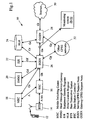
- FIG. 1 shows the major functional components of a GSM network 10 configured to provide GRPS service.
- a mobile station (MS) 12 communicates over an air (RF) interface with a base transceiver station (BTS) 14 under the control of a base station controller (BSC) 16.
- BSC base station controller
- SMS short message service
- SMS Gateway SMSG
- Administrative information about the MS 12 and the subscriber are held in databases comprising an equipment identity register (EIR) 22 and a home location register (HLR) 24.
- EIR equipment identity register
- HLR home location register
- a complete GSM system typically incorporates additional equipment not shown in Figure 1, such as a visitor location register (VLR). However, such equipment that is not directly relevant to implementation of the present invention has been omitted from the figure for the sake of clarity.
- VLR visitor location register
- the system also incorporates a Serving GPRS Support Node (SGSN) 26 and a Gateway GPRS Support Node (SGSN) 28.
- the SGSN 26 routes packet-switched data to and from the MSs within the area it serves. Its principal functions are packet routing, mobile attach and detach procedures, location management, assigning channels and time slots, authentication and charging for calls.
- the GGSN 28 acts as an interface between the GPRS system and the external packet data network, i.e. the internet 30 shown in Figure 1. It converts GPRS packets received via the SGSN 26 into the appropriate Packet Data Protocol format (e.g. Internet Protocol) and forwards them into the external internet 30. Likewise it converts IP addresses in received packets into GSM addresses of destination MSs, and routes the converted packets to the appropriate SGSN 26.
- Packet Data Protocol e.g. Internet Protocol
- the GPRS specifications define various interfaces for connecting the SGSN 26 and GGSN 28 to the other components of the GPRS system, as follows:
- Each interface is implemented by means of a protocol stack, enabling the required functionality to be defined by reference to various widely-used communications protocols, such as the Transmission Control Protocol (TCP), User Datagram Protocol (UDP), GTP and IP.
- TCP Transmission Control Protocol
- UDP User Datagram Protocol
- GTP GTP
- IP IP
- Figure 2 shows the protocol stack for the Gn interface between the SGSN 26 and the GGSN 28.
- user data at layer 34 are encapsulated in TCP or UDP packets comprising the next layer 36, and these are in turn are carried over IP (layer 38 - as shown, either IPv4 or IPv6 can be used).
- the layers 34 to 38 comprise the transport and application layers for use by a subscriber of the IP service provided by GPRS.
- the IP packets in the layer 38 are "tunnelled" over the IP links to the GPRS network elements (particularly the SGSN 26 and the GGSN 28), that is each packet is encapsulated inside another IP packet and carried to the destination without altering the content of the encapsulated packet.
- This approach is adopted in order to prevent the network elements from being addressed directly from outside the network, thereby increasing security.
- This encapsulating packet is formatted as specified in GTP, as shown at 40, with a Message Type (MT) value in the packet header of 255, indicating that the packet contains user data.
- GTP messages are transferred using the UDP path protocol (layer 42), over IPv4 or IPv6 (layer 44).
- the layers 40 to 44 comprise the telecoms tunnel signalling layers.
- the inventors hereof have recognised that, by monitoring packets traversing the Gn interface links (as described below), it is possible to perform both telecoms signalling analysis and service usage analysis at the same time, because the Gn protocol stack contains sufficient information for this purpose.
- Signalling transactions that maintain the GPRS network tunnel can be monitored by a state machine within the monitoring system that refers only to the lowermost three layers (40 to 42) of the stack.
- Service usage by subscribers can be monitored using only the upper three layers (34 to 38) of the stack, but a state machine for doing this has instant access to the signalling information available from the signalling analysis state machine.
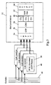
- an SUR generator may be implemented, for example, by combining three complementary state machines:
- the GTP follower state machine processes every message monitored on the Gn interface links. If a message is a GTP signalling message it is processed as follows:
- Gn links 46 are connected to link monitoring cards 48 to enable the packets traversing these links to be passively monitored.
- the monitoring is passive in the sense that the operation of the links 46 is undisturbed by the presence of the connection to the cards 48.
- Each card 48 comprises an interface and a processor operating under the control of software program instructions in a memory (which is also used for data storage).
- the interface couples the respective card 48 to a link 46 in such a way that the operating characteristics of the link are not altered.
- the connection may comprise an optical power splitter; for electrical links the connection may be a bridging isolator, or in the case of an Ethernet network LAN taps may be used.
- Monitoring of the Gn links 46 in this manner enables telecoms signalling analysis and service usage analysis to be performed as described herein in respect of mobile users located within the service area of their "home" network. If the network operator wishes to extend the analysis to include users who are roaming within other GPRS networks 32 ( Figure 1), then monitoring is extended to cover the Gp links connecting the SGSN 26 and the GGSN 28 to those other GPRS networks, as they contain the SGSN/GGSN nodes through which the relevant messages will pass.
- the program instructions for the processor in each monitoring card 48 include code implementing a GTP parser 50, for generating records of the content of IP signalling units.
- the GTP parser 50 selects GTP signalling and protocol messages from the network. It does this by monitoring IP traffic on the Gn interface links and selecting UDP traffic with a source or destination port number of 3386 (GTP v0), 2123 (GTP v1, GTP-C control plane messages) or 2152 (GTP v1, GTP-U user plane messages).
- a further optional stage to the selection of traffic from the network can be applied by filtering on the destination IP address in the outer layer of IPv4/IPv6. This enables traffic destined for the interfaces of one particular network element (GGSN or SGSN) to be selected. It also facilitates the partitioning of IP traffic by address space so that processing capacity can be managed at the level of the monitoring cards 48.
- the GTP header in each selected packet is parsed to extract the MT field value and packets with the following types are selected and time stamped for further processing:
- the selected GTP messages are then forwarded by the link monitoring cards 48 to a central (e.g. site level) server 52 for further processing, where they are received by an Input Manager module 54.
- This module collates and time-orders the GTP messages from the GTP parsers in the monitoring cards. The time ordering is based on a sliding window of the time stamps applied by the GTP parsers, the size of the sliding window being adapted to the volume and throughput of traffic from the input sources.
- the Input Manager modules then passes the time-ordered messages to a GTP module 56 that implements the GTP Follower state machine.
- the GTP module 56 provides two functions. Firstly, it processes GTP signalling messages to maintain its tracking of tunnel state information, and secondly, it forwards all protocol messages that contain a payload length value greater than zero in the GTP header.
- the information provided for each tunnel is:
- Each message processed by the GTP module 56 is examined to see if it is a T-PDU/G-PDU or one of the signalling messages selected by a GTP parser 50. Signalling messages are used by the GTP module 56 to maintain tunnel state information and are not passed on to the other components.
- the T-PDU/G-PDU messages are associated with the tunnel context in which they are being carried and are passed on to the CRG module for further processing.
- the GTP module 56 provides a service interface that the other system components use to obtain access to a per-tunnel data area in which private state information may be kept by each component, and in which the SUR is assembled for output.
- Another service provided by the GTP module 56 is the identification of 'traffic flow direction', information that is made available to the other system modules. Hitherto it has been very difficult to determine with certainty a packet's direction of travel. The problem is to how to identify in an efficient manner whether an IP packet is going from an MS towards the core network (Mobile Originated) or from the core network to the MS (Mobile Terminated). Methods used previously involve identifying all the autonomous system network IP addresses on one side of the monitoring point and maintaining, by manual editing, a list of those addresses. The monitoring system loads the list for comparison to the destination address field in monitored packets, to ascertain whether a packet is coming from or going to an address in the list. Such a list can be very large and easily contain several hundred network addresses and network masks. A further deficiency in this approach is that network administration and routing policies undergo constant change, so the list is usually never a definitive statement of fact, but only a confidence check. The contents can never be created with certainty where interaction between large and dynamic networks is involved.
- both GTPv0 and GTPv1 Create messages always have a source address that is an SGSN interface and a destination address that is a GGSN interface.
- signalling messages are processed (and as new GGSNs are added to the network), monitoring of these signalling messages reveals the new interface addresses.
- the direction of the tunnelled data can be determined from the rule: if the tunnel destination address is a GGSN, the tunnelled data is Mobile Originated, else the tunnelled data is Mobile Terminated.
- this method uses tunnel signalling messages to determine dynamically the IP addresses of the tunnel endpoints.
- Data tunnel Create, Update and Delete signalling messages are used to cache the IP addresses of the servers that provide the network tunnels.
- any GPRS or UMTS network there are relatively few tunnel servers, and tunnels originate at an SGSN and terminate at a GGSN. There are always fewer GGSNs in a network, so the address set for them is smaller than for SGSNs.
- a large network may have, for example, six SGSNs and four GGSNs; each GGSN has two IP network interfaces.
- an IP address set of eight elements would be sufficient to determine the transmission direction of all wireless data traffic in the network.
- a CRG module 58 builds records of TCP and UDP transactions, or 'flow summaries', from the forwarded T-PDU/G-PDU protocol messages, using only the inner or tunnelled IP and TCP/UDP headers (layers 36 and 38 in Figure 2).
- CRG module One function of the CRG module is to aggregate individual measurements into a single summary record. Measurements created by this module may include packet and octet counts attributed to each service activation and the identification of anomalous packet and octet sequences that adversely affect network performance. This count information is conveniently split between upstream (Mobile Originated) and downstream (Mobile Terminated) counts.
- the CRG module 58 processes all the T-PDU/G-PDU messages forwarded by the GTP module 56. However, it will only pass on those actually containing application layer content; those containing only transport signalling are filtered out of the processing stream by this module.
- single CRG module 58 builds summary records for the service activation TCP and UDP transport layers. If it is desired to extend the system's capability to other transports such as Wireless Session Protocol (WSP) and Wireless Datagram Protocol (WDP), which are used to deliver Wireless Application Protocol (WAP) services, a separate Wireless CRG (WCRG) module could be introduced. This new module would process data within the same system as the CRG module 58.
- WSP Wireless Session Protocol
- WDP Wireless Datagram Protocol
- WAP Wireless Application Protocol
- the CRG module 58 monitors the number of simultaneous T-flows with a given GTP Flow summary (G-flow), and upon completion of the service activation (as indicated by a CA module, described below), makes available the whole SUR. For those T-flows that have no CA payload, or protocol that is not TCP, or UDP not equal to 6 or 17, the CRG module 58 outputs the SUR record based on expiry of a timer or when instructed by one of the CA modules 60.
- the messages are forwarded to a set of CA (Content Analysis) modules 60.
- Each module is specialised for the identification and analysis of particular content in the application layer (layer 34 in Figure 2).
- This application content may be a single protocol, or a set of protocols that are used to deliver a service.
- CA modules 60 examine application message header content rather than actual message data. Message headers are assumed to be standard Internet headers as specified in the IETF Request for Comments RFC 822 (Format of ARPA Internet Text Messages).
- the CA modules are organised into a processing chain, for example with the order reflecting the volume of service use in the network. As each module 60 examines a message, it applies tests to determine whether the message should be processed or handed on. If the tests fail, the message is handed on to the next CA module 60 in the chain.
- a special CA module 60 called the null CA module is placed at the end of the CA module processing chain to catch any content not recognised by the CA modules prior to it.
- the null module attempts to use inter-message gap analysis, the message exchange signature and analysis of port numbers to determine when a session activation has begun and ended. Unlike other CA modules it depends on the fact that only one service activation is live within a tunnel at any time, which simplifies the analysis.
- null CA module can continue to operate normally when it is processing encrypted traffic.
- the analysis applied by the module is based purely on timing and traffic exchange patterns and not on the actual content.
- the CA modules 60 are followed by an output formatter 64 that creates the Service Usage Records in the required format and writes them to a specified output stream (file or FIFO buffer).
- the output formatters may for example create an XML (Extensible Markup Language) format SUR, or a binary format V36 structure.
- An SUR is composed of a header followed by three independent sections: G-flow, T-flow and Service Flow summary (S-flow). Each section is independent because they are built using different layers of the stack with no reference to the other layers.
- the SUR has a short header section that identifies the version of SUR format: Field Name Values Comments Version 1..n SUR structure version number.
- the G-Flow section ( ⁇ gtp_flow>) contains information derived by the GTP module 56 from the outer IP, UDP and GTP layers of the stack (layers 40 to 44 in Figure 2) and provides the 'telecoms context' for the following two sections. It also provides summary information on the GTP tunnel. Significant fields in this section include the IMSI, APN, QoS profile, source address (the SGSN) and destination address (the GGSN). Field Name Values Comments gtp_version 0, 1 GTP protocol version. output_reason SgsnlnitDelete GgsnInitDelete ServiceCompletion CreateFail SgsnUpdateFail UpdateFail Explanation of the trigger that caused the SUR build to be terminated and output from SURGE.
- source_address n.n.n.n Source address of tunnel; an SGSN IP interface. destination_address n.n.n.n Destination address of tunnel; a GGSN IP interface.
- the T-Flow section contains measurements derived by the CRG module 58 from the tunnelled IP and TCP/UDP layers (36 and 38 in Figure 2).
- Field Name Values Comments uplink_ip_address n.n.n.n IP address as 4-dotted decimal integers.
- downlink_ip_address n.n.n.n IP address as 4-dotted decimal integers.
- protocol N Protocol number optionally with acronym (e.g. 6 - TCP) type_of_service n TOS field from the IP header.
- uplink_packets 0...n Number of packets. Each fragment counts as one packet.
- Flows can be simplex.
- uplink_octets 0..n Payload octets.
- downlink_octets 0..n Payload octets.
- uplink_anom_pkts 0..n For TCP, a packet with an unexpected sequence number is considered anomalous.
- UDP a packet with the same checksum in recent history is considered anomalous.
- the measure is "the product of the number of jumps and an estimate of median sequence number jump". Alternatively the measure could be an estimate of retransmitted octets.
- uplink_mtu 0..n The maximum size of (possibly fragmented) IP packets downlink_mtu 0..n (octets) The maximum size of (possibly fragmented) IP packets uplink_fragments 0..n Count of IP fragments downlink_fragments 0..n Count of IP fragments uplink_active_secs 0..n The number of active seconds in the flow. downlink_active_secs 0..n The number of active seconds in the flow. uplink_max_throughput 0..n The maximum throughput during an active second. downlink_max_throughput 0..n The maximum throughput during an active second. uplink_min_throughput 0..n The minimum throughput during an active second.
- downlink_min_throughput 0..n The minimum throughput during an active second. uplink_avg_throughput 0..n
- the average throughput during an active second. downlink_avg_throughput 0..n The average throughput during an active second. uplink_first active_sec_ throughput 0..n
- the throughput during the first active second downlink_first active_sec_ throughput 0..n The throughput during the first active second uplink_throughput_variance 0.0..x (as a float)
- min_resp_time 0..n Minimum response time over the set of T-flows in millisecs. max_resp_time 0..n Maximum response time over the set of T-flows in millisecs.
- first_resp_time 0..n Response time of first flow within the G-layer.
- avg_resp_time 0..n Average of all T-layer response times in millisecs. resp_time_variance 0.0..x (float value) Variance of T-layer response times in millisecs squared.
- start_time n m
- First flow start time in secs nanosecs.
- end_time n m
- Simultaneous_tflows 1..n Total number of simultaneous T-flows.
- the S-flow, or ServFlow, section ( ⁇ serv_flow>) is a service- or protocol-specific group of measurements created by the specialised CA modules 60. Sections for HTTP, POP3 and SMTP are defined below. Any other protocol is reported as 'Unknown'.
- the S-flow section suggests whether or not the service activation was successful as a 'service transaction' using the activation_status_code field. A service is deemed to be successful if interaction with the service provider system was possible.
- the activation status code value is present to allow applications such as the GPRS QoS measurement engine to count service activations in the same manner as SS7 TCAP transactions.
- the service status code can be obtained directlv from the protocol.
- activation_status_code n SUR summary status code activation_status_msg string SUR summary status message service_status_code n See RFC2616 section 10 for list.
- service_status_msg string Service/protocol status message start_time n : m Time of first application message response_time n : m Time of first return message end_time n : m Time of last message E-mail Service - POP3 Protocol Field Name Values Comments service_name E-mail content_type POP3 sucessful_item_transfers 1..n Count of items downloaded from server unsuccessful_item transfers 1..n Count of items requested from server but not downloaded max_item_size 1..n Average item size downloaded avg_item_size 1..n Total data downloaded in session total_items_size n : m Time of first message activation_status_code n SUR summary status code activation_status_msg string SUR summary status message service_status_
- service_status_msg string Service/protocol status message start_time n : m Time of first application message response_time n : m Time of first return message end_time n : m Time of last message E-mail Service - SMTP Protocol Field Name Values Comments service_name Email content_type SMTP transfer_direction Sent Received Unknown Indicates direction of transfer for session. An SMTP session may only be one way.
- service_status_msg string Service/protocol status message start_time n : m Time of first application message response_time n : m Time of first return message end_time n : m Time of last message Unknown Services Field Name Values Comments service_name Unknown content_type Unknown activation_status_code n SUR summary status code activation_status_msg string SUR summary status message service_status_code n Service/protocol summary or return code service_status_msg string Service/protocol status message start_time n : m Time of first application message response_time n : m Time of first return message end_time n : m Time of last message No S-flow Records present Field Name Values Comments content_type No Content Seen No application messages have been seen and the SUR contains only G-flow and T-flow values.
Landscapes
- Engineering & Computer Science (AREA)
- Computer Networks & Wireless Communication (AREA)
- Signal Processing (AREA)
- Computer Security & Cryptography (AREA)
- Environmental & Geological Engineering (AREA)
- Business, Economics & Management (AREA)
- Accounting & Taxation (AREA)
- Data Exchanges In Wide-Area Networks (AREA)
- Mobile Radio Communication Systems (AREA)
Abstract
Description
- Figure 1
- is a block schematic diagram of a GSM mobile communications network incorporating equipment for providing GPRS service;
- Figure 2
- shows a protocol stack used on a GPRS Gn interface connecting an SGSN to a GGSN; and
- Figure 3
- is a schematic diagram of major functional blocks in a system for creating SURs.
- Gi, for communications between the GGSN 28 and the
external internet 30; - Gc, for communications between the GGSN 28 and the HLR 24;
- Gn, for communications between the
GGSN 28 and theSGSN 26; - Gr, for communications between the
SGSN 26 and theHLR 24; - Gf, for communications between the
SGSN 26 and the EIR 22; - Gd, for communications between the
SGSN 26 and theSMSG 20 - Gs, for communications between the
SGSN 26 and theMSC 18; - Gb, for communications between the
SGSN 26 and theBSC 16; and - Gp, for communications between from
SGSN 26 and theGGSN 28 to GSNs in other GPRS networks 32.
- a GTP Follower state machine that runs at the telecoms tunnel layer (40 to 44);
- a Call Record Generator (CRG) for the service transport layer (36 and 38);
- and one or more Content Analysis (CA) state machines for the service application layer (34).
- Create PDP Context Request messages and Create PDP Context Response messages are used to construct a CREATE transaction for the tunnel record, and to create internal accounting and control structures for tracking use of the tunnel associated with the requested context. Subscriber IMSI and network APN fields are stored at this point for the tunnel lifetime. The network QoS value is also set at this point, but it may be modified subsequently.
- Update PDP Context Request and Update PDP Context Response messages are used to construct an UPDATE transaction. This is used principally to maintain the network QoS values for the tunnel.
- Delete PDP Context Request and Delete PDP Context Response messages are used to construct a DELETE transaction, which is used to finalise any service usage analysis activities and to destroy the accounting and control structures for the tunnel.
- Create PDP Context Request (MT = 16)
- Create PDP Context Response (MT = 17)
- Update PDP Context Request (MT = 18)
- Update PDP Context Response (MT = 19)
- Delete PDP Context Request (MT = 20)
- Delete PDP Context Response (MT = 21)
- SGSN Context Request (MT = 50)
- SGSN Context Response (MT = 51)
- SGSN Context Acknowledge (MT = 52)
- T-PDU (GTP v0), G-PDU (GTP v1) (MT = 255)
- IMSI and NSAPI (Network Service Access Point Identifier);
- APN;
- QoS Profile;
- Tunnel start address (SGSN);
- Tunnel end address (GGSN).
| Field Name | Values | Comments |
| Version | 1..n | SUR structure version number. |
| Field Name | Values | Comments |
| gtp_version | 0, 1 | GTP protocol version. |
| output_reason | SgsnlnitDelete GgsnInitDelete ServiceCompletion CreateFail SgsnUpdateFail UpdateFail | Explanation of the trigger that caused the SUR build to be terminated and output from SURGE. |
| imsi | 234122334455163 | IMSI of MS attached to tunnel. |
| nsapi | 0 | The NSAPI of the tunnel. |
| apn_string | wap.telco.com | Printable APN for tunnel. |
| apn_hex | 0x377F2C5... | Hex string of unmodified APN value. |
| qos_profile | 0x010203 | Hex string of 3 octet GTP QoS profile requested by the MS in Create PDP Context Request. |
| negot_qos | 0x010203 | Hex string of 3 octet GTP QoS profile granted to the MS in the Create PDP Context Request or in subsequent Update PDP Context Request messages. |
| source_address | n.n.n.n | Source address of tunnel; an SGSN IP interface. |
| destination_address | n.n.n.n | Destination address of tunnel; a GGSN IP interface. |
| uplink_packets | 0..n | Count of GTP messages from SGSN. |
| uplink_octets | 0..n | Count of octets from SGSN. |
| downlink_packets | 0..n | Count of GTP messages from GGSN. |
| downlink_octets | 0..n | Count of octets from GGSN. |
| start_time | n : n | Tunnel creation time. |
| end_time | n : n | Tunnel deletion time. |
| update_requests | 0..n | Count of Update PDP Context Request messages seen for tunnel. |
| init_create_fails | 0..n | |
| sub_create_fails | 0..n | |
| sub_create_successes | 0..n | |
| update_fails | 0..n | |
| update_successes | 0..n | |
| delete_fails | 0..n | |
| unexpected_messages | 0..n |
| Field Name | Values | Comments |
| uplink_ip_address | n.n.n.n | IP address as 4-dotted decimal integers. |
| downlink_ip_address | n.n.n.n | IP address as 4-dotted decimal integers. |
| uplink_port | 1...65365 | TCP or UDP port number. |
| downlink_port | 1...65365 | TCP or UDP port number. |
| protocol | N | Protocol number, optionally with acronym (e.g. 6 - TCP) |
| type_of_service | n | TOS field from the IP header. |
| uplink_packets | 0...n | Number of packets. Each fragment counts as one packet. Flows can be simplex. |
| uplink_octets | 0..n | Payload octets. |
| downlink_packets | 0..n | Number of packets. |
| downlink_octets | 0..n | Payload octets. |
| uplink_anom_pkts | 0..n | For TCP, a packet with an unexpected sequence number is considered anomalous. For UDP, a packet with the same checksum in recent history is considered anomalous. |
| uplink_anom_octets | 0..n | For TCP the measure is "the product of the number of jumps and an estimate of median sequence number jump". Alternatively the measure could be an estimate of retransmitted octets. For UDP, the sum of payload count of anomalous packets. |
| downlink_anom_pkts | 0..n | For TCP, a packet with an unexpected sequence number is considered anomalous. For UDP, a packet with the same checksum in recent history is considered anomalous. |
| downlink_anom_octets | 0..n | For TCP the measure is "the product of the number of jumps and an estimate of median sequence number jump". Alternatively the measure could be an estimate of retransmitted octets. For UDP, the sum of payload count of anomalous packets. |
| uplink_mtu | 0..n (octets) | The maximum size of (possibly fragmented) IP packets |
| downlink_mtu | 0..n (octets) | The maximum size of (possibly fragmented) IP packets |
| uplink_fragments | 0..n | Count of IP fragments |
| downlink_fragments | 0..n | Count of IP fragments |
| uplink_active_secs | 0..n | The number of active seconds in the flow. |
| downlink_active_secs | 0..n | The number of active seconds in the flow. |
| uplink_max_throughput | 0..n | The maximum throughput during an active |
| second. | ||
| downlink_max_throughput | 0..n | The maximum throughput during an active second. |
| uplink_min_throughput | 0..n | The minimum throughput during an active second. |
| downlink_min_throughput | 0..n | The minimum throughput during an active second. |
| uplink_avg_throughput | 0..n | The average throughput during an active second. |
| downlink_avg_throughput | 0..n | The average throughput during an active second. |
| uplink_first active_sec_ throughput | 0..n | The throughput during the first active second |
| downlink_first active_sec_ throughput | 0..n | The throughput during the first active second |
| uplink_throughput_variance | 0.0..x (as a float) | The variance of throughput during the active seconds |
| downlink_throughput_ variance | 0.0..x (as a float) | The variance of throughput during the active seconds |
| resp_time_measures | 0..n | Number of response time measurements made. |
| min_resp_time | 0..n | Minimum response time over the set of T-flows in millisecs. |
| max_resp_time | 0..n | Maximum response time over the set of T-flows in millisecs. |
| first_resp_time | 0..n | Response time of first flow within the G-layer. |
| avg_resp_time | 0..n | Average of all T-layer response times in millisecs. |
| resp_time_variance | 0.0..x (float value) | Variance of T-layer response times in millisecs squared. |
| start_time | n : m | First flow start time in secs : nanosecs. |
| end_time | n : m | Last flow end time in sees : nanosecs. |
| count_tflows | 1..n | Total number of T-flows seen during service session. |
| Simultaneous_tflows | 1..n | Total number of simultaneous T-flows. |
| Web Service - HTTP | ||
| Field Name | Values | Comments |
| service_name | Web | |
| content_type | HTTP | |
| uri | /ads/graphics/cs.gif | Path name portion of URL. |
| activation_status_code | n | SUR summary status code |
| activation_status_msg | string | SUR summary status message |
| service_status_code | n | |
| service_status_msg | string | Service/protocol status message |
| start_time | n : m | Time of first application message |
| response_time | n : m | Time of first return message |
| end_time | n : m | Time of last message |
| E-mail Service - POP3 Protocol | ||
| Field Name | Values | Comments |
| service_name | ||
| content_type | POP3 | |
| sucessful_item_transfers | 1..n | Count of items downloaded from server |
| unsuccessful_item transfers | 1..n | Count of items requested from server but not downloaded |
| max_item_size | 1..n | Average item size downloaded |
| avg_item_size | 1..n | Total data downloaded in session |
| total_items_size | n : m | Time of first message |
| activation_status_code | n | SUR summary status code |
| activation_status_msg | string | SUR summary status message |
| service_status_code | n | |
| service_status_msg | string | Service/protocol status message |
| start_time | n : m | Time of first application message |
| response_time | n : m | Time of first return message |
| end_time | n : m | Time of last message |
| E-mail Service - SMTP Protocol | ||
| Field Name | Values | Comments |
| service_name | ||
| content_type | SMTP | |
| transfer_direction | Sent Received Unknown | Indicates direction of transfer for session. An SMTP session may only be one way. |
| sucessful_item_transfers | 1..n | Count of items downloaded from server |
| unsuccessful_item_ transfers | 1..n | Count of items requested from server but not downloaded |
| Unsuccessful_mails_ sent_up | 1..n | Email items client failed to send to server |
| max_item_size | 1..n | Average item size downloaded |
| avg_item_size | 1..n | Total data downloaded in session |
| total_items_size | n | Time of first message |
| activation_status_code | n | SUR summary status code |
| activation_status_msg | string | SUR summary status message |
| service_status_code | n | |
| service_status_msg | string | Service/protocol status message |
| start_time | n : m | Time of first application message |
| response_time | n : m | Time of first return message |
| end_time | n : m | Time of last message |
| Unknown Services | ||
| Field Name | Values | Comments |
| service_name | Unknown | |
| content_type | Unknown | |
| activation_status_code | n | SUR summary status code |
| activation_status_msg | string | SUR summary status message |
| service_status_code | n | Service/protocol summary or return code |
| service_status_msg | string | Service/protocol status message |
| start_time | n : m | Time of first application message |
| response_time | n : m | Time of first return message |
| end_time | n : m | Time of last message |
| No S-flow Records present | ||
| Field Name | Values | Comments |
| content_type | No Content Seen | No application messages have been seen and the SUR contains only G-flow and T-flow values. |
Claims (14)
- A method of creating service usage records summarising usage of mobile data communications services, comprising:monitoring message packets traversing a signalling link between a serving support node and a gateway support node, said message packets including packets for tunnelling data being transported by a mobile data communications service;extracting from said data tunnelling packets first information relating to data being tunnelled by said packets;extracting from said data tunnelling packets second information relating to implementation of the data tunnelling; andcorrelating said first and second information to generate a service usage record.
- The method of claim 1, wherein the data communications service is a General Packet Radio Service (GPRS), and the signalling link provides a Gn interface between a Serving GPRS Support Node (SGSN) and a Gateway GPRS Support Node (GGSN).
- The method of claim 2, wherein message packets traversing a signalling link providing a GPRS Gp interface are also monitored.
- The method of any one of the preceding claims, wherein the data tunnelling packets are GPRS Tunnelling Protocol (GTP) packets, and packets selected for data extraction have a source or destination port number of 3386, 2123 or 2152.
- The method of claim 4, wherein each data tunnelling packet selected for data extraction has a Message Type field value of 16 to 21, 50 to 52 or 255.
- The method of any one of the preceding claims, wherein the first information includes at least one of International Mobile Subscriber Identity (IMSI), GPRS Access Point Name (APN), Quality of Service (QoS) profile, source address and destination address.
- Apparatus for creating service usage records summarising usage of mobile data communications services, comprising:a monitor for monitoring message packets traversing a signalling link between a serving support node and a gateway support node, said message packets including packets for tunnelling data being transported by a mobile data communications service;a first information extractor for extracting from said data tunnelling packets first information relating to data being tunnelled by said packets;a second information extractor for extracting from said data tunnelling packets second information relating to implementation of the data tunnelling; anda correlator for correlating said first and second information to generate a service usage record.
- The apparatus of claim 7, wherein the data communications service is a General Packet Radio Service (GPRS), and the signalling link provides a Gn interface between a Serving GPRS Support Node (SGSN) and a Gateway GPRS Support Node (GGSN).
- The apparatus of claim 8, including a monitor for monitoring message packets traversing a signalling link providing a GPRS Gp interface.
- The apparatus of any one of claims 7 to 9, wherein the data tunnelling packets are GPRS Tunnelling Protocol (GTP) packets, and packets selected for data extraction have a source or destination port number of 3386, 2123 or 2152.
- The apparatus of claim 10, wherein each data tunnelling packet selected for data extraction has a Message Type field value of 16 to 21, 50 to 52 or 255.
- The apparatus of any one of claims 7 to 11, wherein the first information includes at least one of International Mobile Subscriber Identity (IMSI), GPRS Access Point Name (APN), Quality of Service (QoS) profile, source address and destination address.
- A method of characterising a source of a data packet carrying data in a mobile data communications services, comprising:monitoring message packets traversing a signalling link between a serving support node and a gateway support node, said message packets including packets for tunnelling data being transported by a mobile data communications service;examining a tunnel destination address in each said monitored message packet; andcharacterising the message packet as mobile-originated if the tunnel destination address is a gateway support node and as mobile-terminated if the tunnel destination address is a serving support node.
- Apparatus for characterising a source of a data packet carrying data in a mobile data communications services, comprising:a monitor for monitoring message packets traversing a signalling link between a serving support node and a gateway support node, said message packets including packets for tunnelling data being transported by a mobile data communications service;an address examiner for examining a tunnel destination address in each said monitored message packet; anda packet characteriser for characterising the message packet as mobile-originated if the tunnel destination address is a gateway support node and as mobile-terminated if the tunnel destination address is a serving support node.
Applications Claiming Priority (2)
| Application Number | Priority Date | Filing Date | Title |
|---|---|---|---|
| GB0313812A GB2402845A (en) | 2003-06-14 | 2003-06-14 | Service usage records for mobile data communications |
| GB0313812 | 2003-06-14 |
Publications (3)
| Publication Number | Publication Date |
|---|---|
| EP1487160A2 true EP1487160A2 (en) | 2004-12-15 |
| EP1487160A3 EP1487160A3 (en) | 2014-05-14 |
| EP1487160B1 EP1487160B1 (en) | 2018-08-29 |
Family
ID=27636544
Family Applications (1)
| Application Number | Title | Priority Date | Filing Date |
|---|---|---|---|
| EP04102649.3A Expired - Lifetime EP1487160B1 (en) | 2003-06-14 | 2004-06-10 | Service usage records for mobile data communications |
Country Status (5)
| Country | Link |
|---|---|
| US (1) | US7313108B2 (en) |
| EP (1) | EP1487160B1 (en) |
| JP (1) | JP4542830B2 (en) |
| CN (1) | CN1574983A (en) |
| GB (1) | GB2402845A (en) |
Cited By (5)
| Publication number | Priority date | Publication date | Assignee | Title |
|---|---|---|---|---|
| EP1715622A1 (en) * | 2005-04-19 | 2006-10-25 | Alcatel | Time stamp offset in data packet bundling |
| EP1715623A1 (en) * | 2005-04-19 | 2006-10-25 | Alcatel | Context controlled data tap utilizing parallel logic for integrated link monitoring |
| EP1885084A1 (en) * | 2006-08-04 | 2008-02-06 | Innowireless Co., Ltd. | Method of extracting WAP data using mobile identification number |
| EP2806678A1 (en) * | 2013-05-16 | 2014-11-26 | Tektronix, Inc. | System and method for GTP session persistence and recovery |
| US9036540B2 (en) | 2007-09-28 | 2015-05-19 | Alcatel Lucent | Method and system for correlating IP layer traffic and wireless layer elements in a UMTS/GSM network |
Families Citing this family (31)
| Publication number | Priority date | Publication date | Assignee | Title |
|---|---|---|---|---|
| US7111163B1 (en) | 2000-07-10 | 2006-09-19 | Alterwan, Inc. | Wide area network using internet with quality of service |
| GB2419775B (en) * | 2004-10-28 | 2009-03-25 | Agilent Technologies Inc | Generation of data session records for mobile data communications networks |
| WO2006085292A1 (en) * | 2005-02-14 | 2006-08-17 | Telefonaktiebolaget L M Ericsson (Publ) | Method and nodes for performing bridging of data traffic over an access domain |
| US7907954B2 (en) * | 2005-03-23 | 2011-03-15 | Nokia Corporation | System and method for dynamic interface management |
| JP2008535333A (en) * | 2005-03-31 | 2008-08-28 | テレフオンアクチーボラゲット エル エム エリクソン(パブル) | Large-scale analysis of push-to-talk traffic |
| US7535848B2 (en) * | 2005-05-17 | 2009-05-19 | Tektronix, Inc. | System and method for associating IP services to mobile subscribers |
| US7558234B2 (en) * | 2005-05-17 | 2009-07-07 | Tektronix, Inc. | System and method for correlation of mobile subscriber activity across multiple interfaces in a GPRS network |
| CN101227338B (en) * | 2005-12-22 | 2010-12-08 | 阿尔卡特公司 | Timestamp Offset in Packet Bundle |
| EP1871038B1 (en) * | 2006-06-23 | 2010-06-02 | Nippon Office Automation Co., Ltd. | Network protocol and session analyser |
| US8179895B2 (en) * | 2006-08-01 | 2012-05-15 | Tekelec | Methods, systems, and computer program products for monitoring tunneled internet protocol (IP) traffic on a high bandwidth IP network |
| CN101352093A (en) | 2007-01-08 | 2009-01-21 | 华为技术有限公司 | Forward the learned state information to the moving target node |
| US20100278068A1 (en) * | 2007-04-16 | 2010-11-04 | Neuralitic Systems | Method and System for Filtering IP Traffic in Mobile IP Networks |
| US9379898B2 (en) | 2007-05-04 | 2016-06-28 | Tekelec, Inc. | Methods, systems, and computer program products for providing billing and usage data to downstream applications |
| US8638764B2 (en) * | 2007-11-02 | 2014-01-28 | Broadcom Corporation | Mobile telecommunications architecture |
| KR101375734B1 (en) * | 2008-01-22 | 2014-03-19 | 삼성전자주식회사 | Apparatus and method for accounting in wireless communication system |
| US7454475B1 (en) | 2008-01-26 | 2008-11-18 | International Business Machines Corporation | Method and system for using message content to group messages |
| US10015729B2 (en) * | 2008-11-17 | 2018-07-03 | Telefonaktiebolaget L M Ericsson (Publ) | Providing access to a GPRS network |
| BRPI0823198A8 (en) * | 2008-11-17 | 2015-09-22 | Ericsson Telefon Ab L M | method for providing device access to a general packet radio service network, control node, computer program, and computer readable media product. |
| US8284786B2 (en) * | 2009-01-23 | 2012-10-09 | Mirandette Olivier | Method and system for context aware deep packet inspection in IP based mobile data networks |
| EP3105884A4 (en) | 2014-02-11 | 2018-03-21 | Yaana Technologies, LLC | Mathod and system for metadata analysis and collection with privacy |
| US10447503B2 (en) | 2014-02-21 | 2019-10-15 | Yaana Technologies, LLC | Method and system for data flow management of user equipment in a tunneling packet data network |
| US9693263B2 (en) * | 2014-02-21 | 2017-06-27 | Yaana Technologies, LLC | Method and system for data flow management of user equipment in a tunneling packet data network |
| US10334037B2 (en) | 2014-03-31 | 2019-06-25 | Yaana Technologies, Inc. | Peer-to-peer rendezvous system for minimizing third party visibility and method thereof |
| US10285038B2 (en) | 2014-10-10 | 2019-05-07 | Yaana Technologies, Inc. | Method and system for discovering user equipment in a network |
| US10542426B2 (en) | 2014-11-21 | 2020-01-21 | Yaana Technologies, LLC | System and method for transmitting a secure message over a signaling network |
| GB2534563A (en) | 2015-01-26 | 2016-08-03 | Telesoft Tech Ltd | Data retention probes and related methods |
| US9572037B2 (en) | 2015-03-16 | 2017-02-14 | Yaana Technologies, LLC | Method and system for defending a mobile network from a fraud |
| WO2016176661A1 (en) | 2015-04-29 | 2016-11-03 | Yaana Technologies, Inc. | Scalable and iterative deep packet inspection for communications networks |
| US10135930B2 (en) | 2015-11-13 | 2018-11-20 | Yaana Technologies Llc | System and method for discovering internet protocol (IP) network address and port translation bindings |
| CA3033921C (en) * | 2016-08-15 | 2023-03-14 | Incognito Software Systems Inc. | System and method for bandwidth activity reporting |
| US10862866B2 (en) * | 2018-06-26 | 2020-12-08 | Oracle International Corporation | Methods, systems, and computer readable media for multiple transaction capabilities application part (TCAP) operation code (opcode) screening |
Family Cites Families (22)
| Publication number | Priority date | Publication date | Assignee | Title |
|---|---|---|---|---|
| US4651298A (en) * | 1984-05-30 | 1987-03-17 | The United States Of America As Represented By The Secretary Of The Air Force | Selection of data from busses for test |
| US6137869A (en) * | 1997-09-16 | 2000-10-24 | Bell Atlantic Network Services, Inc. | Network session management |
| FI106509B (en) * | 1997-09-26 | 2001-02-15 | Nokia Networks Oy | Legal interception in a telecommunications network |
| US6463055B1 (en) * | 1998-06-01 | 2002-10-08 | Telefonaktiebolaget L M Ericsson (Publ) | Integrated radio telecommunications network and method of interworking an ANSI-41 network and the general packet radio service (GPRS) |
| US6469998B1 (en) * | 1998-10-06 | 2002-10-22 | Telefonaktiebolaget Lm Ericsson (Publ) | Method and apparatus for communicating data packets from an external packet network to a mobile radio station |
| JP3668047B2 (en) * | 1999-05-20 | 2005-07-06 | 株式会社東芝 | Mobile communication method, mobile computer device and encrypted communication device |
| DE60012580T2 (en) * | 2000-02-11 | 2005-07-28 | Nokia Corp. | METHOD AND SYSTEM FOR IDENTIFICATION INFORMATION DETERMINATION OF A MONITORING PARTICIPANT IN A COMMUNICATION NETWORK |
| FI108491B (en) * | 2000-02-11 | 2002-01-31 | Nokia Corp | Repositioning the serving network element |
| US6999449B2 (en) * | 2000-08-18 | 2006-02-14 | Telefonaktiebolaget Lm Ericsson (Publ) | System and method of monitoring and reporting accounting data based on volume |
| JP3656245B2 (en) * | 2000-12-11 | 2005-06-08 | 日本電気株式会社 | Communication system, detour route resolution method, and recording medium recording detour route resolution program |
| FI112426B (en) * | 2001-03-23 | 2003-11-28 | Nixu Oy | Content server mediation server |
| WO2002082720A2 (en) * | 2001-04-04 | 2002-10-17 | Roke Manor Research Limited | Automated network with tunnels and method of data routing |
| EP1250016A1 (en) * | 2001-04-11 | 2002-10-16 | Lucent Technologies Inc. | Messaging in telecommunications systems |
| US20020150221A1 (en) * | 2001-04-12 | 2002-10-17 | Carson Douglas John | Generating call detail records |
| US20030081607A1 (en) * | 2001-10-30 | 2003-05-01 | Alan Kavanagh | General packet radio service tunneling protocol (GTP) packet filter |
| FI115687B (en) * | 2002-04-09 | 2005-06-15 | Nokia Corp | Transmission of packet data to a terminal equipment |
| WO2004010668A1 (en) * | 2002-07-19 | 2004-01-29 | Nokia Corporation | Route optimizing in mobile ip providing location privacy |
| US7606190B2 (en) * | 2002-10-18 | 2009-10-20 | Kineto Wireless, Inc. | Apparatus and messages for interworking between unlicensed access network and GPRS network for data services |
| US7720960B2 (en) * | 2003-03-04 | 2010-05-18 | Cisco Technology, Inc. | Method and apparatus providing prepaid billing for network services using explicit service authorization in an access server |
| US20040210522A1 (en) * | 2003-04-04 | 2004-10-21 | Bissantz Annette S. | Charging gateway component selection of billing system component to handle charging data record based on one or more characteristics of the charging data record |
| US20050097087A1 (en) * | 2003-11-03 | 2005-05-05 | Punaganti Venkata Murali K. | System and method for providing a unified framework for service discovery |
| US7933290B2 (en) * | 2004-03-30 | 2011-04-26 | Nokia Corporation | System and method for comprehensive service translation |
-
2003
- 2003-06-14 GB GB0313812A patent/GB2402845A/en not_active Withdrawn
-
2004
- 2004-06-08 JP JP2004170273A patent/JP4542830B2/en not_active Expired - Lifetime
- 2004-06-10 US US10/865,573 patent/US7313108B2/en not_active Expired - Lifetime
- 2004-06-10 EP EP04102649.3A patent/EP1487160B1/en not_active Expired - Lifetime
- 2004-06-11 CN CNA2004100465838A patent/CN1574983A/en active Pending
Cited By (7)
| Publication number | Priority date | Publication date | Assignee | Title |
|---|---|---|---|---|
| EP1715622A1 (en) * | 2005-04-19 | 2006-10-25 | Alcatel | Time stamp offset in data packet bundling |
| EP1715623A1 (en) * | 2005-04-19 | 2006-10-25 | Alcatel | Context controlled data tap utilizing parallel logic for integrated link monitoring |
| US8228956B2 (en) | 2005-04-19 | 2012-07-24 | Alcatel Lucent | Time stamp offset in data packet bundling |
| EP1885084A1 (en) * | 2006-08-04 | 2008-02-06 | Innowireless Co., Ltd. | Method of extracting WAP data using mobile identification number |
| US9036540B2 (en) | 2007-09-28 | 2015-05-19 | Alcatel Lucent | Method and system for correlating IP layer traffic and wireless layer elements in a UMTS/GSM network |
| EP2806678A1 (en) * | 2013-05-16 | 2014-11-26 | Tektronix, Inc. | System and method for GTP session persistence and recovery |
| US9298560B2 (en) | 2013-05-16 | 2016-03-29 | Tektronix Texas, Inc. | System and method for GTP session persistence and recovery |
Also Published As
| Publication number | Publication date |
|---|---|
| JP4542830B2 (en) | 2010-09-15 |
| GB2402845A (en) | 2004-12-15 |
| JP2005006312A (en) | 2005-01-06 |
| EP1487160A3 (en) | 2014-05-14 |
| CN1574983A (en) | 2005-02-02 |
| GB0313812D0 (en) | 2003-07-23 |
| US7313108B2 (en) | 2007-12-25 |
| US20040264405A1 (en) | 2004-12-30 |
| EP1487160B1 (en) | 2018-08-29 |
Similar Documents
| Publication | Publication Date | Title |
|---|---|---|
| US7313108B2 (en) | Service usage records for mobile data communications | |
| US20050128967A1 (en) | Identifying services provided via IP and similar packet networks, and service usage records for such services | |
| US6785535B2 (en) | Method for monitoring communications in a cellular radiocommunication system, and network core therefor | |
| EP1671506B1 (en) | Performance management of cellular mobile packet data networks | |
| US8913595B2 (en) | Apparatus and method for enriching data records in a telecommunications network | |
| EP1240772B1 (en) | Methods and systems for analyzing multi-protocol signaling message traffic in a mobile telecommunications network | |
| CN100544473C (en) | Method for determining the performance of a mobile terminal in an operating wireless network | |
| US10638400B1 (en) | Systems and methods of optimal wireless traffic routing | |
| EP2291950B1 (en) | Traffic monitoring by lowest transmission layer marking | |
| US20060274703A1 (en) | Method and apparatus of filtering and viewing real-time detail records based upon user specific criteria | |
| MXPA05007430A (en) | Method and apparatus providing user with account balance notification. | |
| EP2887742B1 (en) | Telecommunications networks | |
| EP2900004A1 (en) | Mobile telecommunications network including a SAVi platform | |
| EP2887614B1 (en) | Telecommunications networks | |
| CN101273578A (en) | Method for listening to GTP-C messages | |
| WO2008097105A1 (en) | Methods, systems and apparatus for monitoring and/or generating communications in a communications network | |
| KR101499022B1 (en) | Apparatus and method for detecting abnormal MMS message in 4G mobile network | |
| US20060092904A1 (en) | Generation of data session records for mobile data communications networks | |
| WO2006016756A1 (en) | Call analysis system in mobile communication network | |
| Botta et al. | A customer service assurance platform for mobile broadband networks | |
| WO2002062037A2 (en) | Call intercept system and method | |
| WO2012136248A1 (en) | Assessing network user quality of experience based on correlation of signaling events | |
| KR20050088596A (en) | The method of configuration and transmission for contents based charging in wcdma | |
| CN1377547A (en) | Method apparatus, and system for enabling communication between second generation and third generation packet data networks | |
| EP1768368A2 (en) | Methods and systems for observing, analyzing and correlating multi-protocol signaling message traffic in a mobile telecommunications network |
Legal Events
| Date | Code | Title | Description |
|---|---|---|---|
| PUAI | Public reference made under article 153(3) epc to a published international application that has entered the european phase |
Free format text: ORIGINAL CODE: 0009012 |
|
| AK | Designated contracting states |
Kind code of ref document: A2 Designated state(s): AT BE BG CH CY CZ DE DK EE ES FI FR GB GR HU IE IT LI LU MC NL PL PT RO SE SI SK TR |
|
| AX | Request for extension of the european patent |
Extension state: AL HR LT LV MK |
|
| RAP1 | Party data changed (applicant data changed or rights of an application transferred) |
Owner name: AGILENT TECHNOLOGIES, INC. |
|
| RAP1 | Party data changed (applicant data changed or rights of an application transferred) |
Owner name: JDS UNIPHASE CORPORATION |
|
| RIC1 | Information provided on ipc code assigned before grant |
Ipc: H04L 12/701 20130101AFI20131216BHEP |
|
| PUAL | Search report despatched |
Free format text: ORIGINAL CODE: 0009013 |
|
| AK | Designated contracting states |
Kind code of ref document: A3 Designated state(s): AT BE BG CH CY CZ DE DK EE ES FI FR GB GR HU IE IT LI LU MC NL PL PT RO SE SI SK TR |
|
| AX | Request for extension of the european patent |
Extension state: AL HR LT LV MK |
|
| RIC1 | Information provided on ipc code assigned before grant |
Ipc: H04L 12/14 20060101AFI20140416BHEP |
|
| 17P | Request for examination filed |
Effective date: 20141114 |
|
| RBV | Designated contracting states (corrected) |
Designated state(s): AT BE BG CH CY CZ DE DK EE ES FI FR GB GR HU IE IT LI LU MC NL PL PT RO SE SI SK TR |
|
| AKX | Designation fees paid |
Designated state(s): DE FR GB |
|
| AXX | Extension fees paid |
Extension state: MK Extension state: LT Extension state: LV Extension state: HR Extension state: AL |
|
| 17Q | First examination report despatched |
Effective date: 20160224 |
|
| RAP1 | Party data changed (applicant data changed or rights of an application transferred) |
Owner name: VIAVI SOLUTIONS INC. |
|
| STAA | Information on the status of an ep patent application or granted ep patent |
Free format text: STATUS: EXAMINATION IS IN PROGRESS |
|
| REG | Reference to a national code |
Ref country code: DE Ref legal event code: R079 Ref document number: 602004053106 Country of ref document: DE Free format text: PREVIOUS MAIN CLASS: H04L0012560000 Ipc: H04L0012140000 |
|
| GRAP | Despatch of communication of intention to grant a patent |
Free format text: ORIGINAL CODE: EPIDOSNIGR1 |
|
| STAA | Information on the status of an ep patent application or granted ep patent |
Free format text: STATUS: GRANT OF PATENT IS INTENDED |
|
| RIC1 | Information provided on ipc code assigned before grant |
Ipc: H04W 4/24 20180101ALI20180117BHEP Ipc: H04L 12/14 20060101AFI20180117BHEP Ipc: H04L 12/70 20130101ALI20180117BHEP |
|
| INTG | Intention to grant announced |
Effective date: 20180219 |
|
| GRAS | Grant fee paid |
Free format text: ORIGINAL CODE: EPIDOSNIGR3 |
|
| GRAJ | Information related to disapproval of communication of intention to grant by the applicant or resumption of examination proceedings by the epo deleted |
Free format text: ORIGINAL CODE: EPIDOSDIGR1 |
|
| GRAL | Information related to payment of fee for publishing/printing deleted |
Free format text: ORIGINAL CODE: EPIDOSDIGR3 |
|
| RAP1 | Party data changed (applicant data changed or rights of an application transferred) |
Owner name: VIAVI SOLUTIONS INC. |
|
| STAA | Information on the status of an ep patent application or granted ep patent |
Free format text: STATUS: EXAMINATION IS IN PROGRESS |
|
| GRAR | Information related to intention to grant a patent recorded |
Free format text: ORIGINAL CODE: EPIDOSNIGR71 |
|
| STAA | Information on the status of an ep patent application or granted ep patent |
Free format text: STATUS: GRANT OF PATENT IS INTENDED |
|
| GRAA | (expected) grant |
Free format text: ORIGINAL CODE: 0009210 |
|
| STAA | Information on the status of an ep patent application or granted ep patent |
Free format text: STATUS: THE PATENT HAS BEEN GRANTED |
|
| INTC | Intention to grant announced (deleted) | ||
| RAP1 | Party data changed (applicant data changed or rights of an application transferred) |
Owner name: VIAVI SOLUTIONS INC. |
|
| AK | Designated contracting states |
Kind code of ref document: B1 Designated state(s): DE FR GB |
|
| INTG | Intention to grant announced |
Effective date: 20180723 |
|
| REG | Reference to a national code |
Ref country code: GB Ref legal event code: FG4D |
|
| REG | Reference to a national code |
Ref country code: DE Ref legal event code: R096 Ref document number: 602004053106 Country of ref document: DE |
|
| RIC2 | Information provided on ipc code assigned after grant |
Ipc: H04W 4/24 20180101ALI20180117BHEP Ipc: H04L 12/14 20060101AFI20180117BHEP Ipc: H04L 12/70 20130101ALI20180117BHEP |
|
| REG | Reference to a national code |
Ref country code: DE Ref legal event code: R097 Ref document number: 602004053106 Country of ref document: DE |
|
| PLBE | No opposition filed within time limit |
Free format text: ORIGINAL CODE: 0009261 |
|
| STAA | Information on the status of an ep patent application or granted ep patent |
Free format text: STATUS: NO OPPOSITION FILED WITHIN TIME LIMIT |
|
| 26N | No opposition filed |
Effective date: 20190531 |
|
| P01 | Opt-out of the competence of the unified patent court (upc) registered |
Effective date: 20230530 |
|
| PGFP | Annual fee paid to national office [announced via postgrant information from national office to epo] |
Ref country code: FR Payment date: 20230626 Year of fee payment: 20 Ref country code: DE Payment date: 20230626 Year of fee payment: 20 |
|
| PGFP | Annual fee paid to national office [announced via postgrant information from national office to epo] |
Ref country code: GB Payment date: 20230627 Year of fee payment: 20 |
|
| REG | Reference to a national code |
Ref country code: DE Ref legal event code: R071 Ref document number: 602004053106 Country of ref document: DE |
|
| PG25 | Lapsed in a contracting state [announced via postgrant information from national office to epo] |
Ref country code: GB Free format text: LAPSE BECAUSE OF EXPIRATION OF PROTECTION Effective date: 20240609 |
|
| PG25 | Lapsed in a contracting state [announced via postgrant information from national office to epo] |
Ref country code: GB Free format text: LAPSE BECAUSE OF EXPIRATION OF PROTECTION Effective date: 20240609 |