EP1486988A2 - Crud-resistant nuclear fuel cladding - Google Patents
Crud-resistant nuclear fuel cladding Download PDFInfo
- Publication number
- EP1486988A2 EP1486988A2 EP04009267A EP04009267A EP1486988A2 EP 1486988 A2 EP1486988 A2 EP 1486988A2 EP 04009267 A EP04009267 A EP 04009267A EP 04009267 A EP04009267 A EP 04009267A EP 1486988 A2 EP1486988 A2 EP 1486988A2
- Authority
- EP
- European Patent Office
- Prior art keywords
- nuclear fuel
- cladding
- fuel assembly
- crud
- polished
- Prior art date
- Legal status (The legal status is an assumption and is not a legal conclusion. Google has not performed a legal analysis and makes no representation as to the accuracy of the status listed.)
- Granted
Links
- 0 C[C@](CC1)*C1*1CC1 Chemical compound C[C@](CC1)*C1*1CC1 0.000 description 2
- SZROXLRJLVSKCD-UHFFFAOYSA-N CCC(CC)(CCC1)C1C(C)C Chemical compound CCC(CC)(CCC1)C1C(C)C SZROXLRJLVSKCD-UHFFFAOYSA-N 0.000 description 1
Images





Classifications
-
- G—PHYSICS
- G21—NUCLEAR PHYSICS; NUCLEAR ENGINEERING
- G21C—NUCLEAR REACTORS
- G21C3/00—Reactor fuel elements and their assemblies; Selection of substances for use as reactor fuel elements
- G21C3/02—Fuel elements
- G21C3/04—Constructional details
- G21C3/06—Casings; Jackets
-
- Y—GENERAL TAGGING OF NEW TECHNOLOGICAL DEVELOPMENTS; GENERAL TAGGING OF CROSS-SECTIONAL TECHNOLOGIES SPANNING OVER SEVERAL SECTIONS OF THE IPC; TECHNICAL SUBJECTS COVERED BY FORMER USPC CROSS-REFERENCE ART COLLECTIONS [XRACs] AND DIGESTS
- Y02—TECHNOLOGIES OR APPLICATIONS FOR MITIGATION OR ADAPTATION AGAINST CLIMATE CHANGE
- Y02E—REDUCTION OF GREENHOUSE GAS [GHG] EMISSIONS, RELATED TO ENERGY GENERATION, TRANSMISSION OR DISTRIBUTION
- Y02E30/00—Energy generation of nuclear origin
- Y02E30/30—Nuclear fission reactors
Definitions
- This invention pertains in general to nuclear fuel element cladding and, more particularly, to a texturized pattern on at least a portion of the nuclear fuel cladding.
- the uranium oxide fuel in a pressurized water reactor is encased in sealed tubes, commonly referred to as the fuel cladding.
- the cladding maintains the fuel in a position, from which controlled fission can proceed and generate heat.
- the cladding then transfers the heat from the fuel to pressurized water that circulates around the primary loop of the reactor coolant system.
- the heated water in the primary loop is used to boil water in a steam generator and the steam is then expanded in a turbine that powers an electrical generator.
- the primary loop is pressurized to prevent boiling on the fuel cladding surface.
- Boiling is undesirable in PWRs because the coolant contains dissolved boric acid and lithium hydroxide.
- the boron-10 isotope in the boric acid controls the reactor power level by absorbing neutrons. Boiling can alter the boron-10 concentration by selective distribution of the boric acid or its salts between liquid and gas phases. Thus, boiling may cause local changes in the neutron flux and power by producing high local concentrations of boron-10.
- the lithium hydroxide will also be concentrated at boiling surfaces and depleted from the steam phase. This is undesirable, since lithium hydroxide is used to control pH within a range that is optimal for minimizing corrosion of system materials. Local changes in lithium hydroxide concentration may move the pH of the reactor coolant water outside the optimum pH range, with the result that corrosion is accelerated.
- Boiling on a PWR fuel cladding surface is also problematic because it encourages the deposition of corrosion products on the cladding surfaces.
- PWR coolant always contains small concentrations of iron, nickel, chromium, zirconium and other metals and metal oxides. These are present in the coolant because of corrosion of the steam generator tubing, the fuel cladding, piping and other materials within the reactor coolant system.
- Deposits on fuel cladding in a PWR are referred to as "crud". The crud deposited on the fuel surfaces becomes activated and then is transported to other parts of the primary system where unwanted radiation fields develop. Furthermore, the crud further accelerates the boiling process and serves as a site for the collection of boron and lithium compounds.
- the power increases have been small enough to minimize the boiling in the "sub-cooled nucleate" mode.
- the cladding temperature exceeds the boiling point that was set by the system pressure (typically, 652.7°F (344.8°C) at 2250 psi (158.2 Kg cm 2 )).
- the temperature of the bulk coolant is below the boiling point so steam bubbles that form on the cladding surface collapse as they grow and contact the cooler bulk water.
- the bubbles in low powered PWR sub-cooled nucleate boiling are small and because they form and collapse so rapidly, deposition of boron and lithium usually does not occur at levels that can be detected.
- higher sub-cooled boiling and thick crud deposits have formed that have amplified the boiling concentration beyond that which is found at a clean surface. Boron deposition has reached high enough levels in some plants to cause flux depressions in the top of the core. In other cases, deposits have caused flux depressions and fuel failure.
- Applicants' field studies as well as theoretical modeling have shown that deposits over 35 microns thick are required to form boron and lithium rich deposits that cause flux depressions.
- an object of this invention to provide an improved cladding that prevents the buildup of thick crud on the cladding surfaces, that is crud more than 35 microns thick.
- This invention achieves the foregoing objectives by providing a nuclear fuel assembly having an array of a plurality of axially-extending elongated tubular nuclear fuel elements respectively encapsulating a fissionable material within at least a portion of the interior volume thereof.
- the surface texture of the cladding varies axially in a prescribed pattern along the cladding.
- the portions of the fuel element cladding that experience sub-cooled nucleate boiling during reactor full power operation that is not insubstantial is polished and the portions of the cladding surface that experience insubstantial or no sub-cooled nucleate boiling during full power reactor operation are abraded, to more evenly distribute the crud over the cladding without incurring deposits in excess of 35 microns.
- the prescribed pattern on the outside of the fuel element cladding extends over the upper third of the axial length of the portion of the cladding encapsulating the fissionable material.
- the polished surface of the prescribed pattern does not have defects in excess of approximately 0.1 microns.
- the polished and abraded surfaces of the cladding alternate in the upper third portion.
- the abraded axial lengths of the cladding are located substantially at or just above at least some of the grid elevations where spacer grids align the fuel elements in the spaced array.
- the polished surfaces include at least one hillock or bump to disrupt the laminar flow of coolant.
- the fuel cladding disclosed in accordance with this invention is designed to prevent the buildup of thick crud, i.e., more than 35 microns thick.
- the process by which thick crud deposits form is complex.
- the boiling rate is certainly an important factor.
- the location of the deposits corresponds to locations where boiling is predicted.
- boiling is not the only criteria for the buildup of thick crud on a fuel cladding surface. Calculation of boiling rates for different assemblies in different reactors has shown that, while the plants affected by thick crud have high boiling rates, there are some plants that have significant boiling but have only thin deposits of crud. The other factors affecting crud buildup are set forth below:
- the water in a pressurized water reactor contains corrosion products in several forms.
- the primary elements are iron and nickel, with lesser amounts of chromium and zirconium. These elements are totally dissolved ions, particulates or colloids.
- a totally dissolved metal consists of a metal ion surrounded by waters of hydration or counter ions such as the borate ion.
- the metal and its coordination sphere are near 1 nanometer in size.
- the colloidal corrosion products range between atomic dimensions and 450 nanometers. They are usually composed of metal oxides and their behaviors, such as agglomeration and attachment to surfaces, are strongly influenced by surface chemistry. Colloidal particles will not settle from a quiescent solution because Brownian forces are large compared to gravitational force.
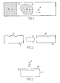
- Corrosion product particles are larger than 450 nanometers. They are also composed of metal oxides. A pictorial comparison of the sizes of the three types of corrosion products are illustrated in Figure 1.
- the dissolved ions in the coolant are represented by reference character 10, the colloids represented by reference character 12 and the metal particles represented by reference character 14.
- the cladding 16 is fabricated from zirconium alloys such as ZIRLOTM or Zircaloy-4. These alloys react rapidly with air or water to form a zirconium oxide film 18.
- the film grows with time, as figuratively depicted by the arrow in Figure 2.
- the film's growth within the reactor occurs by diffusion of oxygen through the film to the metal oxide interface.
- Oxide surfaces have been observed that retain the morphology of the original surface even after two fuel cycles in the reactor (three years).
- Deposition is most likely to be initiated by physical entrapment of small particles by surface defects.
- the particles then serve as seeds for further crystal growth, a process that cements the particles in place.
- Crystal growth can take place with very low super saturation ratios, once a seed is established. Boiling in the vicinity of the defect, which increases the local supersaturation ratio, accelerates the crystal growth process.
- the boiling occurs in the vicinity of trapped particles because the same defects that trap small particles also serve as boiling nucleation sites. Eventually, clusters of particles around multiple defects grow together to form a continuous deposit layer. The boiling nucleation sites turn into steam chimneys that pump additional coolant into the deposit, along with particles and colloids that are then strained from the fluid. Dissolved ions precipitate as the deposit boiling process increases their concentration.
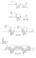
- FIGS 4A-4D Crystals within the deposit continue to grow in size and further cement the structure in place.
- Figures 4A-4D The process is illustrated in Figures 4A-4D.
- Figure 4A figuratively shows a corrosion product particle being detained by a surface defect.
- Figure 4B illustrates that sub-cooled boiling at the defect increases the supersaturation level of dissolved metal ions.
- Figure 4C illustrates that crystal growth takes place starting with the trapped particles serving as a seed. The original particle is cemented into place as it grows and it anchors daughter particles.
- Figure 4D illustrates that the particle's clusters at multiple surface defects grow together to form a continuous deposit layer. Boiling chimneys (steam paths) within the deposit develop and pump more coolant into the deposit. Colloids and particles are added to the deposit and cemented in place by the dissolved ions that precipitate due to the boiling concentration process.
- the growth of the deposit is eventually limited by attrition induced by the primary coolant flow.
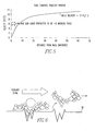
- the flow of the primary coolant in the core of a typical PWR is near 17 feet/second (5.18 meters/second). Even with this high bulk flow, the velocity near the cladding wall is low, and deposits a few microns in thickness will not experience significant shearing force. However, as the deposit increases in thickness, portions of the deposit will extend further into the coolant flow and the shearing force increases.
- a typical coolant velocity profile is shown in Figure 5. This force causes parts of the deposit to spall from the surface as figuratively illustrated in Figure 6. The amount of force a deposit can resist and the limit of its thickness must be a function of how well the deposit is attached to the cladding surface 20.
- crud deposits are held to the surface at attachment points that occupy a small fraction of the crud cladding interface area. Anchoring the crud within surface scratches and other defects is no doubt an important factor in establishing the ultimate thickness of the deposit.
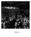
- the process of crud deposit growth just described is supported by applicants' studies of crud deposits, some of the results of which are shown in Figures 7, 8, 9 and 10.
- FIGS. 7, 8 and 9 are scanning electron micrographs with Figure 8 showing a cross-section of a detached cladding oxide that shows a thin crud layer projecting towards the bottom of the image.
- crud thickness profile follows the boiling profile. Little boiling occurs just above the grids due to the turbulence established by the grid mixing vanes. Predictions of deposit thickness, based on the boiling rate, match the observed thickness values reasonably well.
- the predicted thickness values, based on boiling rate and those observed on two typical rods, are shown in Figure 10 where diamonds illustrate measured values and lines are predicted values for the left and right side of the fuel assembly face.
- Crud resistant fuel cladding is fuel cladding with a pattern of surface roughness that has been designed to minimize the buildup of thick crud.
- the portions of the cladding that now experience high mass evaporation rates in PWR cores are given a high polish.
- the high polish minimizes crud buildup by eliminating surface defects that trap the small particles that serve as nucleation sites for crud growth.
- the high polish that is a polish that eliminates surface defects greater than approximately 0.1 microns, also minimizes crud buildup by changing the character of the sub-cooled boiling that takes place. Sub-cooled boiling is suppressed because of a lack of initiation sites, and when it does occur, the bubbles will form randomly across the surface rather than at fixed locations.
- crud-resistant cladding While the crud-resistant cladding is given a high polish in the areas that now experience the most sub-cooled nucleate boiling, the areas that have low boiling rates or do not boil are given a coarse finish. These rough-polished areas of the cladding will serve as "getters" for coolant corrosion products. Crud removed from the coolant onto the rough surfaces will not be available for deposition on surfaces where thick crud deposits have been known to develop. Thus, a thinner and more even distribution of crud is achieved. The crud thickness will not exceed 35 microns at any point, and significant amounts of boron and lithium buildup will be avoided.
- No surface can be without defects, but the highly polished surface must be smooth enough that any surface defects are small enough to exclude the particulate matter that is present in a given coolant system.
- the maximum size for a surface defect on the highly polished surface of crud-resistant cladding is approximately 0.1 microns.
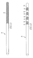
- the high polish is applied to the entire upper portion of the cladding 16, as the shaded area 22.
- the high polish 22 spans the length of the cladding where thick crud deposition has been observed on high-powered fuel. This would be span 5A and above for the current Westinghouse V5H assembly design. In terms of elevation, cladding more than 95 inches (2.41 meters) from the bottom of the assembly would be highly polished. This represents the upper 37% of the power-producing portion of the fuel element.
- the entire length of the cladding 16 could also be polished, depending on the specific reactor application.
- a second embodiment is illustrated in Figure 12, in which the high polish is applied to the upper portion of the cladding, but in a different pattern from the first embodiment in that the polish is applied in bands 22.
- the polish is applied to only the free-span regions of the cladding between spacer grids where boiling would occur with a rough surface. The surface is left in a rough condition within the grids where the power level is lower and the turbulence is higher than the free-span areas and no boiling occurs.
- the cladding is also not polished for a short distance above each grid intersection where turbulence induced by the grid vanes improves heat transfer and suppresses boiling.
- the area shown in Figure 12 that is not shaded 24 is slightly roughened or abraded.
- portions of the cladding 16 are given a high polish as in the first two embodiments.
- small hillocks or bumps 28 are added to the polished section. These hillocks are sized to increase turbulence and disrupt the laminar sublayer of fluid that contacts the cladding. This improves heat transfer with the result that the surface of the tubing is cooler and sub-cooled nucleate boiling is reduced or eliminated.
- the hillocks and the areas surrounding the hillocks are smooth, with no defects larger than approximately 0.1 microns in diameter. Crud buildup is discouraged by the combination of decreased boiling, increased flow turbulence and the lack of particle entrapments sites.
- the ideal height of the hillocks is near 12 microns and their diameter is near 37 microns.
- the distance between the hillocks preferably ranges between 138 and 185 microns.
- Other hillock sizes and shapes may be used, provided that the turbulence at the surface is increased without providing particle entrapment sites.
- the hillocks provide additional benefit by protecting the surrounding polished surface from damage by abrasion. This is particularly true if the hillocks are topped with a hard material with a low co-efficient of friction such as zirconium oxide. This would minimize damage to the fuel cladding when it is loaded into grid assemblies and handling damage would be reduced. Damage by water-borne debris would also be reduced.
- patterned surfaces described in the first two embodiments of the invention can be produced.
- Sufficiently smooth surfaces can be produced by mechanical polishing, chemical polishing (pickling), electropolishing and by laser surface melting.
- the hillocks can be produced by several means as well.
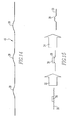
- One way is pictorially illustrated by the flow chart shown in Figure 15.
- a mask 30 that is impervious to a chemical polishing or electropolishing solution, is printed on the surface 20 of the cladding 16 at each location where a hillock 28 is desired.
- the surface 20 of the cladding 16 is polished to preferably remove 12 microns of material.
- the mask 30 is then removed in step 34, exposing the underlying hillock 28.
- the coarse surface of the hillock 28 is thus surrounded by a highly polished surface 20 of the cladding 16.
- FIG. 16 Another technique for creating the desired hillocks 28 on a highly polished surface 20 is illustrated by the flow chart provided in Figure 16.
- a zirconium oxide spot pattern 40 can be produced on the cladding surface 20 in the area where the desired hillock is to be produced.
- Electropolishing and chemical polishing solutions attack zirconium oxide at a very slow rate.
- the hillock 28 that is left will be topped with an abrasion-resistant oxide that will protect the surrounding smooth surface.
- Laser spot heating in an oxygen containing gas can produce the desired oxide pattern on the cladding surface 20.
- An arc discharge 38, especially an arc discharge 38 in a conducting aqueous solution 42, can also produce the oxide pattern.
- a third method illustrated by the flow chart shown in Figure 17, which provides the most flexible way for producing hillocks surrounded by a highly polished surface, is to employ laser surface melting.
- zirconium oxide powder or stabilized zirconium oxide powder is first printed onto the surface 20.
- the zirconium oxide spot is held in place with a binding agent.
- the laser 46 is passed across both the oxide 44 and the tubing surface 20 of the cladding 16, producing an abrasion-resistant hillock on a smooth surface.
- a corrosion-resistant coating is produced by refining the cladding surface 20 by polishing or other means so that the maximum size for a surface defect in the areas that are prone to crud collection is approximately 0.1 microns.
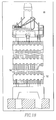
- the cladding of this invention can be employed in a fuel assembly 48 as the outer surface of a plurality of fuel elements 50 maintained in a spaced array by the grids 52 as shown in Figure 18.
Landscapes
- Physics & Mathematics (AREA)
- Engineering & Computer Science (AREA)
- Plasma & Fusion (AREA)
- General Engineering & Computer Science (AREA)
- High Energy & Nuclear Physics (AREA)
- Monitoring And Testing Of Nuclear Reactors (AREA)
- Preventing Corrosion Or Incrustation Of Metals (AREA)
- ing And Chemical Polishing (AREA)
Abstract
Description
Claims (16)
- A nuclear fuel assembly comprising:a spaced array of a plurality of axially extending elongated tubular nuclear fuel elements having first and second closed ends and encapsulating a fissionable material axially along at least a portion of an interior volume thereof and an exterior of at least one of the fuel elements comprising a cladding that extends substantially axially between the first and second closed ends, anda surface texture of said cladding varying axially in a prescribed pattern along the axial length of said cladding between the first and second ends.
- The nuclear fuel assembly of claim 1 wherein the surface texture of said cladding axially varies between and abraded surface and a polished surface along at least a portion of the axial length thereof.
- The nuclear fuel assembly of claim 2 wherein any defects in the polished surface do not substantially exceed 0.1 microns in depth.
- The nuclear fuel assembly of claim 2 or 3 wherein the first closed end of the nuclear fuel element represents an upper end of the nuclear fuel element and the second closed end represents a lower end of the nuclear fuel element and wherein substantially a third or an axial length of the nuclear fuel element housing the fissionable material within the interior volume towards the upper end of the nuclear fuel elements is polished along at least a portion of the axial length thereof.
- The nuclear fuel assembly of claim 4 wherein the third of the axial length of a nuclear fuel element is approximately 241.3 cm (95 inches) or more axially from the second closed end of the nuclear fuel element.
- The nuclear fuel assembly of claim 2 or 3 including a first plurality of axial lengths of said cladding that are polished and a second plurality of axial lengths of said cladding that are abraded and wherein the first and second plurality of axial lengths alternate.
- The nuclear fuel assembly of claim 6 wherein the polished and abraded surfaces of the cladding alternate in the upper third of the axial length of the fuel element housing the fissile material.
- The nuclear fuel assembly of claim 6 or 7 including a plurality of axially spaced spacer grids surrounding and affixing the fuel elements in the spaced array wherein said abraded axial lengths of the cladding are located substantially at or just above at least some of the grid axial elevations.
- The nuclear fuel assembly of any of claims 2 to 8 wherein the or each polished surface includes at least one hillock or bump.
- The nuclear fuel assembly of claim 9 wherein the hillock or bump is sized to increase turbulence and disrupt the laminar sub-layer of a coolant fluid that contacts the cladding during reactor operation.
- The nuclear fuel assembly of claim 9 or 10 wherein the height of the hillocks is approximately 12 microns.
- The nuclear fuel assembly of any of claims 9 to 11 wherein the diameter of the hillocks is approximately 37 microns.
- The nuclear fuel assembly of any of claims 9 to 12 including a plurality of hillocks or bumps wherein the distance between the hillocks or bumps ranges approximately between 138 and 185 microns.
- The nuclear fuel assembly of any of claims 9 to 13 wherein the hillocks are coated with zirconium oxide.
- The nuclear fuel assembly of claim 4 or 5 wherein each axial lengths of the fuel element that experiences sub-cooled nucleate boiling during reactor full power operation that is not insubstantial is polished.
- The nuclear fuel assembly of any of claims 2 to 15 wherein the abraded surfaces are formed at axial locations along the fuel assembly that experience insubstantial or no sub-cooled nucleate boiling during full power reactor operation.
Applications Claiming Priority (2)
| Application Number | Priority Date | Filing Date | Title |
|---|---|---|---|
| US459777 | 1983-01-21 | ||
| US10/459,777 US6813329B1 (en) | 2003-06-12 | 2003-06-12 | Crud-resistant nuclear fuel cladding |
Publications (3)
| Publication Number | Publication Date |
|---|---|
| EP1486988A2 true EP1486988A2 (en) | 2004-12-15 |
| EP1486988A3 EP1486988A3 (en) | 2005-11-30 |
| EP1486988B1 EP1486988B1 (en) | 2008-03-26 |
Family
ID=33299688
Family Applications (1)
| Application Number | Title | Priority Date | Filing Date |
|---|---|---|---|
| EP04009267A Expired - Lifetime EP1486988B1 (en) | 2003-06-12 | 2004-04-20 | Crud-resistant nuclear fuel cladding |
Country Status (6)
| Country | Link |
|---|---|
| US (1) | US6813329B1 (en) |
| EP (1) | EP1486988B1 (en) |
| JP (1) | JP2005003671A (en) |
| KR (1) | KR20040107406A (en) |
| DE (1) | DE602004012657T2 (en) |
| ES (1) | ES2302995T3 (en) |
Cited By (1)
| Publication number | Priority date | Publication date | Assignee | Title |
|---|---|---|---|---|
| US9340845B2 (en) | 2007-12-21 | 2016-05-17 | Areva Np | Method for surface processing a zirconium or hafnium alloy, and component processed in this manner |
Families Citing this family (11)
| Publication number | Priority date | Publication date | Assignee | Title |
|---|---|---|---|---|
| US7123479B2 (en) * | 2003-12-08 | 2006-10-17 | Intel Corporation | Enhanced flow channel for component cooling in computer systems |
| US7132651B2 (en) * | 2004-04-23 | 2006-11-07 | Framatome Anp, Inc. | In-situ BWR and PWR CRUD flake analysis method and tool |
| EP2219191A1 (en) | 2008-09-30 | 2010-08-18 | Areva NP | Cladding tube for nuclear fuel rod, method and apparatus for manufacturing a cladding tube |
| CA2745030C (en) * | 2008-12-01 | 2017-05-02 | Electric Power Research Institute, Inc. | Crystal habit modifiers for nuclear power water chemistry control of fuel deposits and steam generator crud |
| WO2010128691A1 (en) * | 2009-05-04 | 2010-11-11 | 포항공과대학교 산학협력단 | Method for forming fine protrusions on cladding surface of nuclear fuel rod containing zirconium |
| KR20130061202A (en) * | 2011-11-29 | 2013-06-11 | 한국원자력연구원 | The method for treating of neutrons generated from spent nuclear fuel |
| WO2013191743A1 (en) * | 2012-02-17 | 2013-12-27 | The Massachusetts Institute Of Technology | Surface modification of cladding material |
| US9514851B2 (en) * | 2013-03-12 | 2016-12-06 | Westinghouse Electric Company Llc | Rib-type roughness design for improved heat transfer in PWR rod bundles |
| US10276268B2 (en) | 2013-09-03 | 2019-04-30 | Uchicago Argonne, Llc | Coating of nuclear fuel cladding materials, method for coating nuclear fuel cladding materials |
| WO2016179255A1 (en) * | 2015-05-04 | 2016-11-10 | Cerium Laboratories, Llc | Enhanced surface treatments |
| US20230368931A1 (en) * | 2022-05-10 | 2023-11-16 | Westinghouse Electric Company Llc | Fuel cladding covered by a mesh |
Family Cites Families (25)
| Publication number | Priority date | Publication date | Assignee | Title |
|---|---|---|---|---|
| US1929444A (en) * | 1929-07-17 | 1933-10-10 | Murray | Heat conducting element |
| US2181927A (en) * | 1936-04-03 | 1939-12-05 | Albert J Townsend | Heat exchanger and method of making same |
| LU34099A1 (en) * | 1955-02-16 | 1900-01-01 | ||
| US3041262A (en) * | 1956-11-13 | 1962-06-26 | United Nuclear Corp | Reactor fuel element |
| FR1234258A (en) * | 1959-05-13 | 1960-10-17 | Fuel rod with internal channels for nuclear reactor | |
| NL255540A (en) * | 1959-09-04 | |||
| NL298883A (en) * | 1963-09-06 | |||
| FR1444181A (en) * | 1965-05-19 | 1966-07-01 | Commissariat Energie Atomique | nuclear reactor fuel element |
| GB1224465A (en) * | 1967-05-17 | 1971-03-10 | Central Electr Generat Board | Improvements in or relating to fuel element assemblies for nuclear reactors |
| FR2115003B1 (en) * | 1970-11-20 | 1973-11-30 | Commissariat Energie Atomique | |
| FR2136901B1 (en) * | 1971-05-07 | 1975-02-21 | Commissariat Energie Atomique | |
| US3787286A (en) * | 1971-12-17 | 1974-01-22 | Combustion Eng | Fuel assembly flow redistribution |
| DE2255699A1 (en) * | 1972-11-14 | 1974-05-16 | Kernforschung Gmbh Ges Fuer | FUEL ELEMENT FOR A REACTOR |
| GB1459562A (en) * | 1974-03-07 | 1976-12-22 | Atomic Energy Authority Uk | Nuclear reactor fuel elements |
| IT1079560B (en) * | 1977-01-28 | 1985-05-13 | Trojani Benito Luigi | IMPROVEMENT OF LINED PIPES AND MANUFACTURING METHOD OF THEM |
| US4252613A (en) * | 1978-07-26 | 1981-02-24 | The Babcock & Wilcox Company | Nuclear fuel assembly guide tube with integral intermittent projections |
| JPS57166591A (en) * | 1981-04-08 | 1982-10-14 | Hitachi Ltd | Nuclear fuel assembly |
| US5761263A (en) * | 1981-05-14 | 1998-06-02 | Hitachi, Ltd. | Nuclear fuel rod and method of manufacturing the same |
| US4728488A (en) * | 1985-11-14 | 1988-03-01 | Westinghouse Electric Corp. | Wear resistant zirconium base alloy article for water reactors |
| JPH01195391A (en) * | 1988-01-29 | 1989-08-07 | Nuclear Fuel Ind Ltd | Cladding pipe for boiling water reactor fuel |
| US5026516A (en) * | 1989-05-25 | 1991-06-25 | General Electric Company | Corrosion resistant cladding for nuclear fuel rods |
| US5171520A (en) * | 1990-09-04 | 1992-12-15 | Combustion Engineering, Inc. | Wear resistant coating for fuel cladding |
| DE69417941T2 (en) * | 1993-03-02 | 1999-09-30 | Westinghouse Electric Corp., Pittsburgh | Fretting corrosion-resistant fuel rod with a zirconium oxide layer |
| US5437747A (en) * | 1993-04-23 | 1995-08-01 | General Electric Company | Method of fabricating zircalloy tubing having high resistance to crack propagation |
| US6005906A (en) * | 1996-06-12 | 1999-12-21 | Siemens Power Corporation | Corrosion and hydride resistant nuclear fuel rod |
-
2003
- 2003-06-12 US US10/459,777 patent/US6813329B1/en not_active Expired - Lifetime
-
2004
- 2004-04-20 EP EP04009267A patent/EP1486988B1/en not_active Expired - Lifetime
- 2004-04-20 DE DE602004012657T patent/DE602004012657T2/en not_active Expired - Lifetime
- 2004-04-20 ES ES04009267T patent/ES2302995T3/en not_active Expired - Lifetime
- 2004-05-13 JP JP2004143999A patent/JP2005003671A/en active Pending
- 2004-06-11 KR KR1020040042927A patent/KR20040107406A/en not_active Ceased
Cited By (1)
| Publication number | Priority date | Publication date | Assignee | Title |
|---|---|---|---|---|
| US9340845B2 (en) | 2007-12-21 | 2016-05-17 | Areva Np | Method for surface processing a zirconium or hafnium alloy, and component processed in this manner |
Also Published As
| Publication number | Publication date |
|---|---|
| DE602004012657T2 (en) | 2009-06-18 |
| JP2005003671A (en) | 2005-01-06 |
| ES2302995T3 (en) | 2008-08-01 |
| DE602004012657D1 (en) | 2008-05-08 |
| EP1486988B1 (en) | 2008-03-26 |
| KR20040107406A (en) | 2004-12-20 |
| US6813329B1 (en) | 2004-11-02 |
| EP1486988A3 (en) | 2005-11-30 |
Similar Documents
| Publication | Publication Date | Title |
|---|---|---|
| EP1486988B1 (en) | Crud-resistant nuclear fuel cladding | |
| US8983019B2 (en) | Superwetting surfaces for diminishing leidenfrost effect, methods of making and devices incorporating the same | |
| Une et al. | Crystallography of zirconium hydrides in recrystallized zircaloy-2 fuel cladding by electron backscatter diffraction | |
| Xu et al. | Oxidation behavior of grain boundary engineered alloy 690 in supercritical water environment | |
| Park et al. | Effects of oxidation states of fuel cladding surface on crud deposition in simulated primary water of PWRs | |
| Veleva et al. | Hydride embrittlement and irradiation effects on the hoop mechanical properties of pressurized water reactor (PWR) and boiling-water reactor (BWR) ZIRCALOY cladding tubes: Part II. Morphology of hydrides investigated at different magnifications and their interaction with the processes of plastic deformation | |
| Jiang et al. | Waterside corrosion of M5 alloy in lithiated/borated and supercritical water: Influences of aqueous environments | |
| Siddiqui et al. | A comprehensive review on the use of nanoparticles in nuclear power plants | |
| Yang et al. | Microstructural understanding on the fouling behavior of crud on PWR fuel cladding surface | |
| Hatano et al. | Influence of size distribution of Zr (Fe, Cr) 2 precipitates on hydrogen transport through oxide film of Zircaloy-4 | |
| Lister et al. | Nuclear plant materials and corrosion | |
| JP6409051B2 (en) | New substances made from uranium, gadolinium and oxygen and their use as depleting neutron poisons | |
| Hawkes | The simulation and study of conditions leading to axial offset anomaly in pressurized water reactors | |
| Byers et al. | Potential crud related margin gains with chromium coated zirconium cladding | |
| Nordin | Effect of Surface Finish on Corrosion and Deuterium Pickup in Zr-2.5 Nb Pressure Tubes | |
| Wang | Spent-fuel special-studies progress report: probable mechanisms for oxidation and dissolution of single-crystal UO/sub 2/surfaces | |
| Tawfeeq et al. | Effect of Sequential Helium and Nickel Ion Implantation on the Nano-Indentation Hardness of X750 Alloy | |
| Kim et al. | Progress of U-Mo Dispersion rod fuel qualification program in Korea | |
| Gray | Spent fuel dissolution rates as a function of burnup and water chemistry | |
| Atchison et al. | On the use of lead/tin alloys as target material for the production of spallation neutrons | |
| de Pierrefeu | The dissolution behaviour of magnetite electrodes in high-temperature water | |
| Raj et al. | Nanotechnologies in Sodium‐Cooled Fast Spectrum Reactor and Closed Fuel Cycle Sustainable Nuclear Energy System | |
| Peybernes et al. | Characterization of the parameters at the origin of the chemical species hideout process at the fuel rod surface in boiling conditions | |
| Guoqing et al. | Research on Crud Deposition of Zr-4 and N36 Zirconium Alloys in Simulated | |
| Elliott et al. | CRUD Source Term Assessment and Development for VERA |
Legal Events
| Date | Code | Title | Description |
|---|---|---|---|
| PUAI | Public reference made under article 153(3) epc to a published international application that has entered the european phase |
Free format text: ORIGINAL CODE: 0009012 |
|
| AK | Designated contracting states |
Kind code of ref document: A2 Designated state(s): AT BE BG CH CY CZ DE DK EE ES FI FR GB GR HU IE IT LI LU MC NL PL PT RO SE SI SK TR |
|
| AX | Request for extension of the european patent |
Extension state: AL HR LT LV MK |
|
| PUAL | Search report despatched |
Free format text: ORIGINAL CODE: 0009013 |
|
| RIC1 | Information provided on ipc code assigned before grant |
Ipc: 7C 23F 15/00 B Ipc: 7G 21C 3/06 A |
|
| AK | Designated contracting states |
Kind code of ref document: A3 Designated state(s): AT BE BG CH CY CZ DE DK EE ES FI FR GB GR HU IE IT LI LU MC NL PL PT RO SE SI SK TR |
|
| AX | Request for extension of the european patent |
Extension state: AL HR LT LV MK |
|
| 17P | Request for examination filed |
Effective date: 20051103 |
|
| AKX | Designation fees paid |
Designated state(s): DE ES FR SE |
|
| GRAP | Despatch of communication of intention to grant a patent |
Free format text: ORIGINAL CODE: EPIDOSNIGR1 |
|
| GRAS | Grant fee paid |
Free format text: ORIGINAL CODE: EPIDOSNIGR3 |
|
| GRAA | (expected) grant |
Free format text: ORIGINAL CODE: 0009210 |
|
| AK | Designated contracting states |
Kind code of ref document: B1 Designated state(s): DE ES FR SE |
|
| REF | Corresponds to: |
Ref document number: 602004012657 Country of ref document: DE Date of ref document: 20080508 Kind code of ref document: P |
|
| REG | Reference to a national code |
Ref country code: SE Ref legal event code: TRGR |
|
| REG | Reference to a national code |
Ref country code: ES Ref legal event code: FG2A Ref document number: 2302995 Country of ref document: ES Kind code of ref document: T3 |
|
| ET | Fr: translation filed | ||
| PLBE | No opposition filed within time limit |
Free format text: ORIGINAL CODE: 0009261 |
|
| STAA | Information on the status of an ep patent application or granted ep patent |
Free format text: STATUS: NO OPPOSITION FILED WITHIN TIME LIMIT |
|
| 26N | No opposition filed |
Effective date: 20081230 |
|
| REG | Reference to a national code |
Ref country code: FR Ref legal event code: PLFP Year of fee payment: 13 |
|
| REG | Reference to a national code |
Ref country code: FR Ref legal event code: PLFP Year of fee payment: 14 |
|
| REG | Reference to a national code |
Ref country code: FR Ref legal event code: PLFP Year of fee payment: 15 |
|
| PGFP | Annual fee paid to national office [announced via postgrant information from national office to epo] |
Ref country code: FR Payment date: 20190320 Year of fee payment: 16 |
|
| PGFP | Annual fee paid to national office [announced via postgrant information from national office to epo] |
Ref country code: DE Payment date: 20190318 Year of fee payment: 16 Ref country code: ES Payment date: 20190503 Year of fee payment: 16 |
|
| PGFP | Annual fee paid to national office [announced via postgrant information from national office to epo] |
Ref country code: SE Payment date: 20190409 Year of fee payment: 16 |
|
| REG | Reference to a national code |
Ref country code: DE Ref legal event code: R119 Ref document number: 602004012657 Country of ref document: DE |
|
| PG25 | Lapsed in a contracting state [announced via postgrant information from national office to epo] |
Ref country code: DE Free format text: LAPSE BECAUSE OF NON-PAYMENT OF DUE FEES Effective date: 20201103 Ref country code: SE Free format text: LAPSE BECAUSE OF NON-PAYMENT OF DUE FEES Effective date: 20200421 Ref country code: FR Free format text: LAPSE BECAUSE OF NON-PAYMENT OF DUE FEES Effective date: 20200430 |
|
| REG | Reference to a national code |
Ref country code: ES Ref legal event code: FD2A Effective date: 20210903 |
|
| PG25 | Lapsed in a contracting state [announced via postgrant information from national office to epo] |
Ref country code: ES Free format text: LAPSE BECAUSE OF NON-PAYMENT OF DUE FEES Effective date: 20200421 |