EP1486840A1 - Automobile manufacturing line input order planning apparatus - Google Patents
Automobile manufacturing line input order planning apparatus Download PDFInfo
- Publication number
- EP1486840A1 EP1486840A1 EP03744503A EP03744503A EP1486840A1 EP 1486840 A1 EP1486840 A1 EP 1486840A1 EP 03744503 A EP03744503 A EP 03744503A EP 03744503 A EP03744503 A EP 03744503A EP 1486840 A1 EP1486840 A1 EP 1486840A1
- Authority
- EP
- European Patent Office
- Prior art keywords
- building
- vehicles
- building sequence
- sequence
- vehicle
- Prior art date
- Legal status (The legal status is an assumption and is not a legal conclusion. Google has not performed a legal analysis and makes no representation as to the accuracy of the status listed.)
- Withdrawn
Links
Images











Classifications
-
- G—PHYSICS
- G05—CONTROLLING; REGULATING
- G05B—CONTROL OR REGULATING SYSTEMS IN GENERAL; FUNCTIONAL ELEMENTS OF SUCH SYSTEMS; MONITORING OR TESTING ARRANGEMENTS FOR SUCH SYSTEMS OR ELEMENTS
- G05B19/00—Program-control systems
- G05B19/02—Program-control systems electric
- G05B19/418—Total factory control, i.e. centrally controlling a plurality of machines, e.g. direct or distributed numerical control [DNC], flexible manufacturing systems [FMS], integrated manufacturing systems [IMS] or computer integrated manufacturing [CIM]
- G05B19/41865—Total factory control, i.e. centrally controlling a plurality of machines, e.g. direct or distributed numerical control [DNC], flexible manufacturing systems [FMS], integrated manufacturing systems [IMS] or computer integrated manufacturing [CIM] characterised by job scheduling, process planning, material flow
-
- G—PHYSICS
- G05—CONTROLLING; REGULATING
- G05B—CONTROL OR REGULATING SYSTEMS IN GENERAL; FUNCTIONAL ELEMENTS OF SUCH SYSTEMS; MONITORING OR TESTING ARRANGEMENTS FOR SUCH SYSTEMS OR ELEMENTS
- G05B19/00—Program-control systems
- G05B19/02—Program-control systems electric
- G05B19/418—Total factory control, i.e. centrally controlling a plurality of machines, e.g. direct or distributed numerical control [DNC], flexible manufacturing systems [FMS], integrated manufacturing systems [IMS] or computer integrated manufacturing [CIM]
-
- G—PHYSICS
- G05—CONTROLLING; REGULATING
- G05B—CONTROL OR REGULATING SYSTEMS IN GENERAL; FUNCTIONAL ELEMENTS OF SUCH SYSTEMS; MONITORING OR TESTING ARRANGEMENTS FOR SUCH SYSTEMS OR ELEMENTS
- G05B2219/00—Program-control systems
- G05B2219/30—Nc systems
- G05B2219/31—From computer integrated manufacturing till monitoring
- G05B2219/31056—Selection of assembly processes, preferred assembly sequences
-
- G—PHYSICS
- G05—CONTROLLING; REGULATING
- G05B—CONTROL OR REGULATING SYSTEMS IN GENERAL; FUNCTIONAL ELEMENTS OF SUCH SYSTEMS; MONITORING OR TESTING ARRANGEMENTS FOR SUCH SYSTEMS OR ELEMENTS
- G05B2219/00—Program-control systems
- G05B2219/30—Nc systems
- G05B2219/31—From computer integrated manufacturing till monitoring
- G05B2219/31384—Produce construction sequence, make parts, store, assemble equipment, ship
-
- G—PHYSICS
- G05—CONTROLLING; REGULATING
- G05B—CONTROL OR REGULATING SYSTEMS IN GENERAL; FUNCTIONAL ELEMENTS OF SUCH SYSTEMS; MONITORING OR TESTING ARRANGEMENTS FOR SUCH SYSTEMS OR ELEMENTS
- G05B2219/00—Program-control systems
- G05B2219/30—Nc systems
- G05B2219/31—From computer integrated manufacturing till monitoring
- G05B2219/31415—Cost calculation in real time for a product manufactured
-
- Y—GENERAL TAGGING OF NEW TECHNOLOGICAL DEVELOPMENTS; GENERAL TAGGING OF CROSS-SECTIONAL TECHNOLOGIES SPANNING OVER SEVERAL SECTIONS OF THE IPC; TECHNICAL SUBJECTS COVERED BY FORMER USPC CROSS-REFERENCE ART COLLECTIONS [XRACs] AND DIGESTS
- Y02—TECHNOLOGIES OR APPLICATIONS FOR MITIGATION OR ADAPTATION AGAINST CLIMATE CHANGE
- Y02P—CLIMATE CHANGE MITIGATION TECHNOLOGIES IN THE PRODUCTION OR PROCESSING OF GOODS
- Y02P90/00—Enabling technologies with a potential contribution to greenhouse gas [GHG] emissions mitigation
- Y02P90/02—Total factory control, e.g. smart factories, flexible manufacturing systems [FMS] or integrated manufacturing systems [IMS]
Definitions
- the present invention relates to a building sequence planning system for an automobile production line, which prepares a building sequence and a work sequence for each of plural processes. More particularly, the present invention relates to a building sequence planning system for throwing automobile into an automobile production line, which is suitable for use in the manufacturing industry employing a mixed line, represented by the automobile manufacturing industry.
- automobiles are generally manufactured through a plurality of processes, such as a body process (main and metal), a painting process (paint), an assembly process (trim), and a final test process (final).
- a body process main and metal
- painting process paint
- assembly process trim
- final final
- respective stations are interconnected by rails, and vehicles are moved at equal intervals and at a constant speed, while a work load and a work time are different for each process.
- it is required to decide a work sequence in the various processes without producing an extra vehicle standing by between the processes and causing necessity of exchange in the vehicle sequence, for example, so that respective lines constitute one continuous line.
- the building sequence can be decided only by a skilled person having a thorough knowledge of all matters in the production line, such as operations in respective processes, line characteristics, attributes of vehicles flowing along the line, and details of operations depending on specifications and options.
- Fig. 1 is a system block diagram showing the overall construction of the building sequence planning system for the automobile production line according to one embodiment of the present invention.
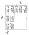
- Fig. 2 is a system block diagram showing a detailed construction of a principal part of the building sequence planning system for the automobile production line, shown in Fig. 1, according to this embodiment.
- the building sequence planning system for the automobile production line comprises an input unit 1, a processing unit 3, an output unit 5, and memories 2, 4, 6, 7 and 8.
- the input unit 1 comprises a LAN device 1a, a keyboard 1b, a display device 1c, and an input storage 1d.
- the input storage 1d stores therein information entered by using the keyboard 1b and the display device 1c, and information entered from another external device in accordance with communication procedures for the LAN device 1a or the like.
- the information inputted through the input unit 1 contains, for example, the following items:
- the processing unit 3 prepares a building sequence schedule based on the input information from the input unit 1.
- the memory 4 stores a group of programs executed by the processing unit 3.
- the processing unit 3 executes necessary processing in accordance with the group of programs stored in the memory 4.
- the processing unit 3 comprises a sequence preparing unit 3a, a time-of-day assigning unit 3b, and a chassis No. assigning unit 3c.
- the sequence preparing unit 3a prepares a successive building sequence for each process based on the input information.
- the prepared successive building sequence information is stored in the memory 6. The detailed construction of the sequence preparing unit 3a will be described later with reference to Fig. 2.
- the time-of-day assigning unit 3b executes processing for assigning the time of day in the actual calendar to the successive building sequence information that is an output result of the sequence preparing unit 3a and is stored in the memory 6.
- the assigned actual-calendar information is stored in the memory 7.
- the chassis No. assigning unit 3c assigns the chassis number (No.), i.e., the body management number, per vehicle in the successive building sequence that is stored in the memory 7 and is added with the time of day, thereby providing unique data. At the time when the chassis number is assigned, an end user is united. Data of each vehicle assigned with the chassis number is stored in the memory 8.
- the output unit 5 comprises a printer 5a, a display device 5b, a schedule storage 5c, and a LAN device 5d.
- the output unit 5 is accessible to the memories 6, 7 and 8 in which the processing results of the sequence preparing unit .3a, the time-of-day assigning unit 3b, and the chassis No. assigning unit 3c are stored, and is capable of referring to the building sequence information, i.e., the processing result of the processing unit 3. Also, the output unit 5 outputs vehicle building time-of-day sequence information with specifications per sequence decision point. Further, the output unit 5 performs outputting of a work instruction, etc.
- data can be corrected through the display device 5b in a dialog way.
- the sequence preparing unit 3a comprises an input information taking-in unit 31, a carry-over fixated range deciding unit 32, an initial offline sequence preparing unit 33, an initial lead-time developing unit 34, a sequence evaluating unit 35, an evaluation determining and storing unit 36, an end-of-processing determining unit 37, an offline sequence preparing unit 38, and a lead-time developing unit 39.
- Fig. 3 is a flowchart of the processing executed by the sequence preparing unit 3a in the building sequence planning system for the automobile production line according to one embodiment of the present invention.
- step s10 the input information taking-in unit 31 reads information from the input storage 1d of the input. unit 1 and loads the information into the memory.
- step s15 the carry-over fixated range deciding unit 32 compares carry-over information, i.e., information regarding vehicles for which work is not yet started in the building sequence schedule range previously outputted with a building sequence schedule previously outputted, and fixates vehicles not designated by the carry-over information, i.e., vehicles for which work has been already started, in all the processes, thereby setting those vehicle to be not exchanged in sequence. Because work is performed from the head process, the carry-over information is instructed in a sequence decision point process at the head. The building sequence is fixated while tracking a designated vehicle toward downward processes from the head sequence decision point. Additionally, an interrupt is allowed for a vehicle that is to be manufactured in response to a newly received instruction.
- carry-over information i.e., information regarding vehicles for which work is not yet started in the building sequence schedule range previously outputted with a building sequence schedule previously outputted
- fixates vehicles not designated by the carry-over information i.e., vehicles for which work has been already started, in all the processes, thereby setting those vehicle
- the initial offline sequence preparing unit 33 prepares an initial building sequence at an offline point (so called because the vehicle having completed assembly leaves the line here) where an assembly process is completed. While the initial building sequence may be at random, suitability of an initial array sequence affects the number of searches until an array sequence as an optimum building sequence is obtained. In practice, an initial array sequence is prepared in consideration of leveling of specifications and options so that the number of convergences until reaching the optimum building sequence is reduced.
- the initial lead-time developing unit 34 shifts a lead time for modification based on the initial array sequence prepared by the initial offline sequence preparing unit 33, and develops the sequence to preceding and succeeding target processes for which the sequence is to be prepared. Details of the lead-time shifting and the lead-time modification will be described later with reference to Figs. 16 to 20.
- step s30 the sequence evaluating unit 35 evaluates the building sequence for all the processes, which has been prepared by the initial lead-time developing unit 34.
- the evaluation in this step includes the steps of checking portions not satisfying requirements set for the specifications and the options, and calculating a penalty value whenever each of those portions is detected.
- the building sequence for all the processes is checked with respect to all of the specifications and the options, and a total penalty value is calculated. The penalty value will be described below with reference to Figs. 6 to 15.
- step s35 the evaluation determining and storing unit 36 stores the penalty value in the memory 6 when the initial sequence is evaluated.
- the evaluation determining and storing unit 36 compares the calculated penalty value with the stored one and stores the better penalty value in the memory 6.
- step s40 the offline sequence preparing unit 38 prepares another pattern of the successive building sequence in an offline process by using a random number.
- step s45 the lead-time developing unit 39 shifts a lead time to the preceding and succeeding processes for modification based on the offline sequence newly prepared by the offline sequence preparing unit 33, thereby preparing the successive building sequence for the entire process.
- step s50 the sequence evaluating unit 35 evaluates the building sequence for the entire process and calculates an evaluation value (penalty value).
- step s55 the evaluation determining and storing unit 36 compares the newly calculated evaluation value with the stored one.
- step s60 the evaluation determining and storing unit 36 determines whether the evaluation value is improved. If the evaluation value is improved, the control flow proceeds to step s65, and if not improved, it proceeds to step s70.
- the evaluation determining and storing unit 36 adopts the newly prepared building sequence for all the sequence decision points and stores it in the memory 6 in step s65.
- the evaluation determining and storing unit 36 discards the newly prepared building sequence for all the sequence decision points in step s70.
- step s75 the end-of-processing determining unit 37 checks in step s75 whether repetitive searches have been completed in a predetermined number of times. If repetitive searches have been completed in the predetermined number of times, the processing is brought to an end. If not so, the control flow returns to step s40 to repeatedly execute the above-described processing.
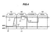
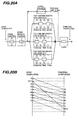
- Fig. 4 is an illustration for explaining one example of basic processes and production lines in an automobile manufacturing factory for which a building sequence is to be prepared by the building sequence planning system for the automobile production line according to one embodiment of the present invention.
- the entire process is mainly divided into, for example, four processes, i.e., a body process ("main” or “metal”) K1, a painting process ("paint”) K2, an assembly process (“trim”) K3, and a final process (“final”) K4.
- the manufacturing process advances in the order of the body process, the painting process, the assembly process, and the final process.
- the body process K1 is a process for welding and working a vehicle frame.
- the painting process K2 is a process for painting the body.
- the assembly process K3 is usually called a trimming process, and it is a process for assembling the specifications and the options.
- arrow-headed thin lines denote production lines L.
- Each vehicle advances in the direction of arrows along the lines L in such a state as resting on a carriage, while passing successive stages of work so that the vehicle gradually approaches the completed form.
- various stations are interconnected by rails along the corresponding lines L, and the vehicles are moved at equal intervals and at a constant speed.
- the lines L include, by way of example, main lines L1, L2.
- a line L3 laid in the body process K1 is separated from the line L2 and joins with the line L1.
- a loop-like line L4 laid in the painting process K2 is separated from a part of the line L1 and then joins with the line L1 again after moving the vehicle in the direction opposite to the line L1.
- a line L5 laid in the painting process K2 is similarly separated from a part of the line L2 and then joins with the line L2 again after moving the vehicle in the direction opposite to the line L2.
- These lines L4, L5 are used to pass the vehicle through a painting booth twice and to perform painting twice, for example, in the case of panting the vehicle in two-tone colors.
- a line L6 laid in the assembly process K3 is separated from the line L1 and then joins with the line L1 again in the final process K4.
- a thick line represents a manufacturing route MR per vehicle type.
- a sedan type manufacturing route MR1 a mini-van and wagon type manufacturing route MR2, and an RV type manufacturing route MR3.
- mini-van and wagon type vehicles and RV type vehicles are manufactured along the line L2.
- mini-van and wagon type vehicles have frames closer to those of RV type vehicles than those of sedan type vehicles
- the mini-van and wagon type vehicles and the RV type vehicles are manufactured along the same line L2.
- looking at painting work because painting of the mini-van and wagon type vehicles is closer to that of the sedan type vehicles from the viewpoint of the vehicle shape, e.g., the vehicle height, those two types of vehicles are painted along the line L1.
- the line L3 is provided for separation and joining between the lines L2 and L1.
- the independent line L6 is provided in the assembly process K3 in addition to the lines L1 and L2.
- a buffer allowing one or more vehicles to stand therein is often provided between adjacent two of the four main processes.
- a sequence of vehicles can be exchanged in the buffer, but the following description is made on the premise of first-in first-out equipment.
- Fig. 5 is an illustration for explaining one example of building sequence decision points used in the building sequence planning system for the automobile production line according to one embodiment of the present invention. Note that the same symbols as those in Fig. 4 denote the same components.
- Fig. 5 shows checkpoints P in manufacturing processes obtained by breaking down the main processes shown in Fig. 4. While there are usually 15 to 20 checkpoints in the automobile manufacturing industry, the description is made in connection with typical 6 points for simplicity of explanation. More specifically, as shown in Fig. 5, a setup point P1 and a body completion point P2 are set respectively at an inlet and an outlet of the body process K1. Also, a painting completion point P3 is set at an outlet of the painting process K2. An assembly entry point P4 and an offline point P5 are set respectively at an inlet and an outlet of the assembly process K3. Further, a final completion point P6 is set at an outlet of the final process K4.
- the manufacturing route of the vehicle to be manufactured can be represented by using numbers shown in Fig. 5.
- the manufacturing route MR2 for the mini-van type, shown in Fig. 4 is represented by "setup 3" - "body completion 1" - "painting 1” - "assembly entry 1" - "offline 2" - "final completion 1". These numbers are each called a line section and expressed by "311121".
- building sequence at each point means a sequence at which vehicles pass the relevant building sequence decision point. Because the vehicles are subjected to line work and cannot pass the relevant point at the same time, the sequence at which the vehicles pass at certain time differences is called here the building sequence or the successive building sequence or simply the sequence.
- restriction conditions in preparing the building sequence which are set for specifications and options and are used in the building sequence planning system for the automobile production line according to this embodiment.
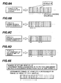
- Fig. 6 is an illustration for explaining one example of restriction conditions in preparing the building sequence, which are set for specifications and options and are used in the building sequence planning system for the automobile production line according to one embodiment of the present invention.
- the first condition is leveling based on an occupancy rate, as shown in Fig. 6(A). Assuming a vehicle having specifications A to be a vehicle A, this condition means that when the vehicle A occupies 30% of all vehicles ordered to be assembled, the vehicles A are desirably arranged in an evenly distributed way with respect to remaining 70% vehicles other than A. For example, when there are 20 assembled vehicles and the number of the vehicles A among them is six as shown in Fig. 6(A), the vehicles A are assigned such that they are distributed as the first, fourth, eighth, eleventh, fourteenth and seventeenth vehicles.
- the second condition is the minimum interval vehicle number in Fig. 6(B), and this condition means that at least a designated number of vehicles other than A are desirably sandwiched between two vehicles A.
- the minimum interval vehicle number is one as shown in Fig. 6(B)
- the vehicles A are assigned as the first, third, seventh, ninth, fourteenth and twentieth ones so that one or more vehicles other than A are sandwiched between two vehicles A.
- the third condition is the maximum succeeding vehicle number shown in Fig. 6(C), and this condition means that the vehicles A may be successively arranged, but the number of succeeding vehicles is desirably held not larger than a designated value at maximum. For example, when the maximum succeeding vehicle number is three as shown in Fig. 6(C), the vehicles A are assigned as the second, third, eighth, tenth, eleventh and twelfth ones so that the vehicles A are successively arranged until three at maximum.
- the fourth condition is a lot condition shown in Fig. 6(D), and this condition means that the vehicles A are desirably assigned as a lot in which they are successively arranged in what number at minimum and at maximum. For example, assuming that there are 24 assembled vehicles and the number of the vehicles A among them is ten and that the lot condition is five at maximum and two at minimum, as shown in Fig. 6(D), the vehicles A are assigned as the first, second, third, ninth, tenth, eleventh, twelfth, thirteenth, twenty-first and twenty-second ones so that the vehicles A are successively arranged in number five at maximum and two at minimum.
- the fifth condition is the assignment range designation shown in Fig. 6(E), and this condition means in which range of all orders the vehicles A should be loaded. This represents designation inherently resulting from a condition such as a unit load per transport track. Therefore, the assignment range is designated in terms of time zone from what time to what time, or in terms of rate indicating that the vehicles A are loaded for production from what % to what % of all the orders counting from the head. For example, assuming that there are 30 assembled vehicles (offline vehicles) and the number of the vehicles A among them is seven and that the assignment range designation is 0 to 50%, as shown in Fig. 6(E), the vehicles A are assigned as the first, fourth, sixth, ninth, eleventh, thirteenth and fifteenth ones so that the vehicles A are arranged in the range of 0 to 50%, i.e., in the range of first to fifteenth vehicles.
- any other suitable condition than the above-described ones can also be set additionally.
- essential ones among the five kinds of conditions shown in Figs. 6(A) to 6(E) are four, i.e., A: occupancy rate leveling, B: minimum interval vehicle number, C: maximum succeeding vehicle number, and D: lot condition.
- the condition of E: assignment range designation can be set as required.
- Fig. 7 is an illustration for explaining the method of calculating the penalty for the occupancy rate leveling condition among the restriction conditions used in the building sequence planning system for the automobile production line according to one embodiment of the present invention.
- the leveling condition based on the occupancy rate is a condition that, as shown in Fig. 6(A), when the vehicle A occupies 30% of all vehicles ordered to be assembled, the vehicles A are desirably arranged in an evenly distributed way with respect to remaining 70% vehicles other than A. For example, as shown in Fig. 7, when there are 10 assembled vehicles and the number of the vehicles A among them is three, the vehicles A are assigned such that they are distributed as the first, fourth and tenth vehicles. The penalty calculated in such a case is described here.
- the interval vehicle number is 2 and 5. These values differ from the expected interval vehicle number 2.3, and hence penalties are applied to both the intervals.
- the penalty value is calculated from a formula of (penalty weight) ⁇ (square of absolute value of difference from the expected interval vehicle number).
- negative impression is quantified in terms of penalty.
- a negative value increases. This means that a smaller negative value (closer to 0) represents a better case.
- the penalty in the case of the two-vehicle interval is -0.45 point, and the penalty in the case of the five-vehicle interval is -36.45 points.
- the penalty is generated in any of the cases that the vehicles A are too close to each other and that they are too away from each other.
- Fig. 8 is an illustration for explaining the method of calculating the penalty for the minimum interval vehicle number condition among the restriction conditions used in the building sequence planning system for the automobile production line according to one embodiment of the present invention.
- the penalty value is calculated from a formula of (penalty weight) ⁇ (square of absolute value of difference from the designated minimum interval vehicle number). Assuming, for example, that the minimum interval vehicle number is two and four vehicles A are assigned in an array sequence of 8 vehicles as the first, third, seventh and eighth ones, as shown in Fig. 8, a penalty is applied to the interval between the first and third vehicles because the number of vehicles in that interval is one, but no penalty is applied to the interval between the third and seventh vehicles because the number of vehicles in that interval is three. Further, a penalty is applied to the interval between the seventh and eighth vehicles because the number of vehicles in that interval is zero.
- Fig. 9 is an illustration for explaining the method of calculating the penalty for the maximum succeeding vehicle number condition among the restriction conditions used in the building sequence planning system for the automobile production line according to one embodiment of the present invention.
- the penalty value is calculated from a formula of (penalty weight) ⁇ (square of absolute value of difference from the designated maximum succeeding vehicle number). Assuming, for example, that the maximum succeeding vehicle number is three and nine vehicles A are assigned in an array sequence of 13 vehicles as the first, second, sixth, seventh, eighth, ninth, eleventh, twelfth and thirteenth ones, as shown in Fig. 9, no penalty is applied to the range of the first to second vehicles because the number of succeeding vehicles in that range is two, but a penalty is applied to the range of the sixth to ninth vehicles because the number of succeeding vehicles in that range is four. Further, no penalty is applied to the range of the eleventh to thirteenth vehicles because the number of succeeding vehicles in that range is three.
- the penalty value can be likewise calculated for the lot condition shown in Fig. 6(D) and the assignment range designation shown in Fig. 6(E).
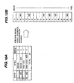
- Figs. 10 and 11 are each an illustration for explaining the building sequence preparing process executed in the building sequence planning system for the automobile production line according to one embodiment of the present invention.
- step s20 of Fig. 3 the initial offline sequence preparing unit 33 prepares the initial building sequence at the offline point where the assembly process is completed.
- Fig. 10(A) there are 20 vehicles having three kinds of specifications (specs), i.e., sedan (S), mini-van (M) and 4WD (WD), and two kinds of specifications are set for each vehicle, as shown in Fig. 10(A).
- the initial array sequence is prepared using a random number for the 20 vehicles, i.e., 3 sedan types, 2 (sedan + 4WD) types, 11 mini-van types, and 4 (mini-van + 4WD) types, it is obtained, by way of example, as shown in Fig. 10(B).
- the 20 vehicles are arranged in an array sequence of, from the head, sedan, mini-van, mini-van + 4WD, sedan, mini-van, sedan + 4WD, and so on.
- the offline sequence preparing unit 38 prepares another pattern of the successive building sequence in the offline process by using a random number.
- a uniform random number corresponding to the number of orders i.e., a random number causing numerals of 1 to 20 to appear at the same probability in this embodiment
- a new array sequence is produced by exchanging the vehicles at positions indicated by those random numbers. For example, the array sequence shown in Fig. 11(A) (which is the same as that shown in Fig. 10(B)) is changed based on two random numbers into a new array sequence shown in Fig. 11(B).
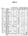
- Figs. 12 to 15 are each a table for explaining the evaluation value calculating process executed in the building sequence planning system for the automobile production line according to one embodiment of the present invention.
- Fig. 12 shows a table for evaluating the restriction conditions with respect to the specifications and the occupancy rate.
- the restriction condition with respect to the specification "sedan” is that the minimum interval vehicle number is one.
- the restriction condition with respect to the specification “4WD” is that the minimum interval vehicle number is two.
- the restriction condition with respect to the specification "mini-van” is that the maximum continuous vehicle number is three.
- the leveling condition based on the occupancy rate is set for all the specifications.
- the penalty weight applied to the restriction conditions with respect to the specifications and the occupancy rate is assumed to be -5.
- step s30 of Fig. 3 the sequence evaluating unit 35 evaluates the building sequence for all the processes, which has been prepared by the initial lead-time developing unit 34.
- the evaluation in this step includes the steps of checking portions not satisfying requirements set for the specifications and the options, and calculating a penalty value whenever each of those portions is detected.
- the building sequence for all the processes is checked with respect to all of the specifications and the options, and a total penalty value is calculated.
- Fig. 13 shows, by way of example, a result of evaluating the initial building sequence, shown in Fig. 10(B), by using the evaluation table, shown in Fig. 12, for the restriction conditions with respect to the specifications and the occupancy rate.
- the penalty value with respect to the leveling of the occupancy rate is described.
- the expected. interval vehicle number is 3.
- the penalty value with respect to the restriction conditions is described.
- the specification "sedan” is subjected to the restriction condition that the minimum interval vehicle number is "1".
- the sedan is assigned as the first, fourth, sixth and fourteenth vehicle
- the interval between two sedans includes two, one and seven vehicles, respectively, and therefore no penalty is applied.
- respective values are obtained as "0", "0", "0” and "-5".
- a total penalty value is "-5".
- mini-van the penalty value with respect to the maximum succeeding vehicle number is calculated and a total penalty value of "-100" is obtained.
- seven mini-vans continue from the seventh to thirteenth vehicle.
- a grand total of the penalty values for the array sequence shown in Fig. 13 is "-316.85".
- Fig. 14 shows, by way of example, a result of evaluating the building sequence after the exchange, shown in Fig. 11(B), by using the evaluation table, shown in Fig. 12, for the restriction conditions with respect to the specifications and the occupancy rate.
- step s40 of Fig. 3 After the offline sequence preparing unit 38 prepares, in step s40 of Fig. 3, another pattern of the successive building sequence in the offline process by using a random number, the sequence evaluating unit 35 evaluates the building sequence for all the processes and calculates the evaluation value (penalty value) in step s50.
- a calculation method is the same as that described above with reference to Fig. 13.
- a grand total of the penalty values for the array sequence shown in Fig. 14 is "-291.85" that shows a better result than the initial array sequence.
- Fig. 15 shows an array sequence and an evaluation result at which the total penalty value is minimized.
- the search including sequence exchange is performed in the designated number of times as described above in connection with step s75 of Fig. 3.
- the evaluation value (penalty value) is improved from the previous one, the newly prepared building sequence for all the sequence decision points is adopted and stored in step s65.
- the building sequence thus decided is shown in Fig. 15.
- a convergence speed to the optimum array sequence can be increased.
- the use of a genetic algorithm is able to further increase the convergence speed. It is also possible to control the final sequence as intended by a designer depending on the evaluation formula and the weight used in the calculation.
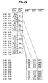
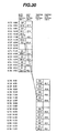
- Figs. 16 to 20 are each an illustration for explaining the lead-time shifting process executed in the building sequence planning system for the automobile production line according to one embodiment of the present invention.
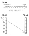
- Fig. 16 illustrates the lead-time shifting in connection with, by way of example, the assembly process K3 shown in Fig. 5.
- Figs. 16(A), 16(B) and 16(C) each square box represents one vehicle.
- Fig. 16(A) shows a state in which eight vehicles reside between the assembly entry process (point P4 in Fig. 5) and the offline process (point P5 in Fig. 5).
- the work time required for one vehicle is 1 hour (i.e., in the case of 1 vehicle/Hr), it takes 8 hours to reach the offline process from the assembly entry process.
- Fig. 16(B) shows the building sequence in the assembly entry process
- Fig. 16(C) shows the building sequence in the offline process.
- the relevant vehicle should be obtained at 17:00 in the offline process as shown in Fig. 16(C)
- it is required to loaded such that the assembly entry process is completed 8 hours before, namely at 8:00, based on the line speed and the number of residing vehicles in the assembly process, i.e., 8 vehicles + 1 vehicle/Hr.
- the array sequence can be transferred to the preceding process in consideration of the number of residing vehicles and the treatment speed.
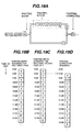
- Fig. 17 illustrates the lead-time shifting in connection with, by way of example, the case in which the storage is provided between the painting process K2 and the assembly process K3 shown in Fig. 5.
- Figs. 17(A), 17(B), 17(C) and 17(D) each square box represents one vehicle.
- the buffer i.e., the so-called storage, capable of accommodating 8 vehicles is provided between the painting completion point P3 in the painting process K2 and the assembly entry point P4 in the assembly process K3 shown in Fig. 5.
- the painting process having a lower capability continues operation to send the vehicles into the storage in the time zone during which the assembly process is in rest, thereby maintaining a speed balance between those two processes.
- the working time of the painting process having a lower capability is increased so that the vehicles are accumulated in the storage.
- Fig. 17(B) shows the building sequence at the painting completion point
- Fig. 17(C) shows the number of vehicles remaining in the storage
- Fig. 17(D) shows the building sequence in the assembly entry process.
- the lead-time shifting in the storage can be performed based on the number of vehicles accumulated in the storage. Assuming, for example, that the vehicle A shown in Fig. 17(D) is to be loaded into the assembly entry point at 12:00, if the number of vehicles remaining in the storage at that time is "3", the vehicle A requires to be loaded into the painting completion point in the painting process at 8:00 by going back for a time corresponding to three vehicles.
- the lead-time shifting can be performed based on the balance calculation of the number of vehicles in the storage, which is made taking into account the number of vehicles accumulated in the storage shown in Fig. 17 in combination with the number of residing vehicles shown in Fig. 16.
- the term "balance calculation” used herein means an operation of calculating the number of vehicles coming into and going out from the storage in respective temporal sections at which the vehicles come in from the preceding process and go out to the succeeding process, thereby determining the number of vehicles remaining in the storage.
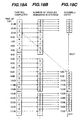
- Fig. 18(A) On the painting completion side, as shown in Fig. 18(A), the production is continuously performed while periods of rest time (e.g., 3:00 to 4:00 and 12:00 to 13:00) are set during the continuous work. In the process on the assembly entry side, as shown in Fig. 18(C), the production is performed while taking a rest in a part of shifts (e.g., 23:00 to 8:00 and 12:00 to 13:00) so that a line capability is held in sync with the painting completion side. On the assembly entry side, one vehicle is assembled per 30 minutes at a capability twice that on the painting completion side. The painting completion side continues the production at a capability of one vehicle per hour.
- Fig. 18(B) shows changes in the number of vehicles remaining in the storage in the above-described case.
- Fig. 18 shows an example in which a balance is taken between two processes. Looking at a vehicle Z on the assembly entry side, it is a vehicle for which the painting is completed at 23:00. To assign the vehicle Z in the assembly entry process at 8:00, in this embodiment, balance tracing is made on coming-in and going-out of vehicles to and from the storage, shown in Fig. 18(B), in respective temporal sections at which vehicles come into and go out from the storage. In the section of the time (8:00) at which the vehicle Z is taken into the assembly entry point, the number of vehicles remaining in the storage is 8. Accordingly, the number 8 means that the vehicle Z is to be placed in the position having skipped back 8 vehicle production frames in the painting completion process (namely going back a corresponding period of time).
- the vehicle Z is assigned in the production frame starting from 22:00 by skipping the production frames for 8 vehicles, i.e., vehicles h, g, f, e, d, c, b and a, from the time 8:00.
- the illustrated example shows that, when there is a difference in capability between the preceding and succeeding processes, any difference in capability or any difference in operation time can be absorbed by controlling the number of vehicles accumulated in the storage.
- Fig. 19(A) shows an example of two-tone color painting.
- a vehicle Y requiring the two-tone color painting has to pass a painting booth twice.
- the vehicle Y is subjected to a first loop of painting in the painting booth after the painting entry process, and then it enters again the painting booth via a bypass line for a second loop of painting.
- Fig. 19(B) Assuming, as shown in Fig. 19(B), that vehicles are arranged in a sequence of X, Y, 1, 2, 3, 4, 5, 6 and 7 in the first loop of painting, because the vehicle Y enters the second loop as shown in Fig. 19(C), vehicles are arranged in a sequence of X, Y, 1, 2, 3, 4, 5, 6, Y and 7 at that time. As shown in Fig. 19(D), therefore, the sequence at the painting completion point is given as X, "Empty", Y, 1, 2, 3, 4, 5, 6, Y and 7. Thus, the vehicles cannot be obtained in the sequence of X, Y, 1, 2, 3, ... in the painting completion process.
- the sequence can be adaptively exchanged if a time required for the vehicle to move along a route for the second loop of painting can be confirmed.
- the above-mentioned problem can be overcome by building the relevant vehicle into the painting entry process at a 2-hour earlier timing. Modifying the sequence based on the time required for moving along the bypass line, etc. in such a way is herein called lead-time modification.
- the lead-time modification can be performed in terms of time or number of vehicles.
- the painting process in the automobile manufacturing industry comprises the steps of prime painting (generally electrodoposition coating), intermediate painting, top painting, and oven (baking).
- the top painting step is made up of a plurality of painting booths (i.e., a top painting booth for a paint color A, a top painting booth for a paint color B, and a top painting booth for a paint color C). Note that the paint color in the painting booth is not fixed, but it can be changed or replaced.
- a passage time through the painting booth differs depending on the specs.
- the passage time through the painting booth for a vehicle having a paint color A is 20 minutes
- the passage time through the painting booth for a vehicle having a paint color B is 15 minutes
- the passage time through the painting booth for a vehicle having a paint color C is 10 minutes.
- a return step for two-tone color painting requires a passage time of 25 minutes, including taping work.
- the sequence can be simply decided by employing the passage time as a lead-time shifting time at the body completion point.
- the passage time for example, a total of 50 minutes, i.e., the passage time of 15 minutes for B + the passage time of 25 minutes for taping + the passage time of 10 minutes for C, is set as the lead time.
- Each dotted line in Fig. 20(B) represents a time interval of 5 minutes.
- the building sequence at the desired point can be decided while skipping detailed restrictions inside the plant.
- Figs. 21 to 25 are each a table for explaining one example of information inputted to the building sequence planning system for the automobile production line according to one embodiment of the present invention.
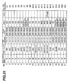
- Fig. 21 shows one example of assembled vehicle order information inputted to the input unit 1 in Fig. 1.
- An example of actually operating, based on the order information, the building sequence planning system for the automobile production line according to this embodiment is described with reference to the drawings subsequent to Fig. 22.
- each vehicle can be set to have any of four specifications, i.e., CD, car navigation, 4WD, and two-tone color.
- the line section means the manufacturing route. Based on the production line shown in Fig. 4, the building sequence is prepared at each of the sequence decision points shown in Fig. 5.
- the offline date means a scheduled day on which the relevant vehicle is made offline at the final completion point P6 shown in Fig. 5.
- No. 1 is an order for a sedan (S) having a red paint color.
- the line section "111111” means that the sequence decision points shown in Fig. 5 are given as “setup 1" - "body completion 1" - "painting 1” - "assembly entry 1" - "offline 1” - “final completion 1". Thus, it represents the manufacturing route MR1 for the sedan shown in Fig. 4.
- the offline date is August 30, 2000.
- "CD" is set as one of the specifications.
- No. 15 is an order for a mini-van (M) having two-tone paint colors of read and black.
- the line section "311121” means that the sequence decision points shown in Fig.
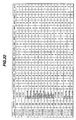
- Fig. 22 shows one example of the sequence decision point information inputted to the input unit 1 in Fig. 1.
- One column item “line section” in Fig. 22 includes three kinds of number strings, i.e., "111111”, “311121” and “333333”, which represent respectively the three production lines MR1, MR2 and MR3 shown in Fig. 4.
- Another item “month” represents the production month, e.g., "August", in this example.
- An item “point name” represents one of the setup point P1, the body completion point P2, the painting completion point P3, the assembly entry point P4, the offline point P5, and the final completion point P6 shown in Fig. 5. Those points are set in one-to-one relation to the respective production lines.
- Still another item "24D” represents D (daytime) work on 24th day, and “24N” represents N (nighttime) work on 24th day.
- a numeral per work shift represents the number of vehicles that are scheduled to finish manufacturing in each process during the relevant work shift.
- sequence decision point information indicates the number of vehicles that are scheduled to finish manufacturing during each work shift at each point per production line.
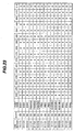
- Fig. 23 shows one example of information regarding the designated number of residing vehicles described above with reference to Fig. 16.
- One column item “line section” in Fig. 23 includes three kinds of number strings, i.e., "111111”, “311121” and “333333”, which represent respectively the three production lines MR1, MR2 and MR3 shown in Fig. 4.
- Another item “month” represents the production month, e.g., "August", in this example.
- An item “point name” represents a line between two adjacent processes unlike the "point name” in Fig. 22. More specifically, "body” represents an inter-process line from the setup to the body completion, and “painting” represents an inter-process line from the body completion to the painting completion.
- PBS and "assembly” represent an inter-process line from the painting completion to the assembly entry
- final represents an inter-process line from the offline to the final completion.
- Still another item "24D” represents D (daytime) work on 24th day, and “24N” represents N (nighttime) work on 24th day.
- a numeral per work shift represents the number of vehicles that are scheduled to finish manufacturing in each process during the relevant work shift.
- the residing-vehicle designated number information indicates the designated number of residing vehicles during each work shift at each point per production line.
- the designated number of residing vehicles is information that requires to be checked when the lead-time shifting is made between two relevant processes.
- Fig. 24 shows one example of basic information for evaluation with respect to the specs (specifications), which is inputted to the input unit 1 in Fig. 1.
- the basic information for evaluation is inputted in the form of a table indicting evaluation conditions.
- Each number in a column item "point” in Fig. 24 corresponds to one of the sequence decision points from the setup point P1 to the final completion point P6 shown in Fig. 5.
- "CD” and “car navigation” are set, by way of example, as “SPEC (specifications)”.
- the designation in the table of Fig. 24 is alterable and the prepared sequence can be controlled by properly setting the conditions on the table of Fig. 24.
- Fig. 25 shows a modification condition for a two-tone color.
- SPEC specifications
- a column “modification time” indicates the necessity of modifying the schedule by 120 minutes.
- the modification can also be made based on "the number of vehicles".
- a merit in designating the modification condition based on "the number of vehicles" is that an expected sequence interrupt can be set without depending on the length of a tact (shift work time / number of vehicles manufactured during shift). Stated another way, it is easier to define joint from a branch line to a main line in the case of a bypassing line in consideration of a merit from the viewpoint of time.
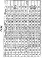
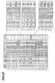
- Figs. 26 to 32 are each a table for explaining one example of the building sequence information prepared by the building sequence planning system for the automobile production line according to one embodiment of the present invention.
- the building sequence information comprises the following items, i.e., vehicle series, paint color, line section, setup point time, body completion point time, painting completion point time, assembly entry point time, offline point time, final completion point time, and specifications (SPEC1, SPEC2).
- the vehicle series “S (sedan)" in the first row has the respective items defining the paint color "red”, the line section "111111", the setup point time “8/24 17:00", the body completion point time “8/25 16:30", the painting completion point time “8/28 16:30", the assembly entry point time "8/29 17:00", the offline point time "8/30 17:00”, the final completion point time "8/31 16:30", and specifications (SPEC1, SPEC2) "CD”.
- the vehicle series, the paint color, the line section, the offline point time, and the specifications (SPEC1, SPEC2) are the same as those shown in Fig. 21.
- the information in Fig. 26 is set so that the vehicles listed in Fig. 21 reach the offline point at the offline point time designated in Fig. 21 (2001/08/30 for each vehicle). Further, the building sequence and the time at each point are set so as to satisfy those conditions.
- Fig. 27 is a table obtained by taking out the building sequence in the offline process shown in Fig. 26, distributing the vehicles to the offline lines 1, 2 and 3, and rearranging the building sequence for each offline line. Because of employing different lines, this table includes the settings at the same time of day.
- Fig. 28 shows the lead-time shifting from the offline process to the assembly entry process. Because there are neither branches nor joints in the lines between those two processes, the building sequence in the assembly entry process is decided in conformity with the offline sequence.
- Fig. 29 shows the lead-time shifting from the assembly entry process to the painting completion process. It is understood that the assembly entry lines 1, 2 are concentrated in the painting completion line 1.
- Fig. 30 shows the lead-time shifting from the painting completion process to the body completion process. Because a vehicle M15 having the "'two-tone" specification takes a longer time for the two-tone color painting, it is loaded in the body completion process with a lead-time shift corresponding to the time required for the two-tone color painting.
- Fig. 31 shows the lead-time shifting from the body completion process to the setup. As will be seen, vehicles in "body completion 1" are separated into “setups 1 and 3".
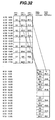
- Fig. 32 shows the lead-time shifting from the offline to the final completion process.
- An automobile is a product having an extremely high production cost, and therefore overstocked inventories accompany a serious risk. Also, with regard to the problems such as in what kinds of specifications and options the inventories should be prepared, an automobile maker is required to minimize the inventories or to have no inventories. Further, for the purpose of maintaining competitiveness, it is required to shorten a period from an order to delivery (called a lead tame on the maker side) and to improve customer's satisfaction. Additionally, an increase of operation efficiency in a factory results in a larger number of vehicles manufactured per day and a lower production cost.
- the building sequence for each of the preceding and succeeding processes is decided while performing the lead-time shifting and the lead-time modification.
- the thus-decided building sequence is checked in accordance with the preset evaluation conditions for the specifications and the options. Whenever an offensive portion is detected, a penalty value is calculated based on the preset weight and evaluation formula, and a building sequence providing a minimum penalty value is obtained through repeated searches. As a result, a building sequence schedule ensuring high operability can be prepared in a short time.
- a building sequence satisfying requirements of a plurality of processes in a well-balanced manner can be easily prepared in a mixed line including branches and joints, whereby "quick” and "efficient” planning can be realized. Further, added values are obtained in not only cutting the time required for planning the building sequence and extending the time limit for an order, but also in increasing the working efficiency and ensuring rigid adherence to the production frame (i.e., the number of vehicles manufactured).
- a building sequence planning system for an automobile production line can be provided which is able to prepare an efficient building sequence.
Landscapes
- Engineering & Computer Science (AREA)
- General Engineering & Computer Science (AREA)
- Manufacturing & Machinery (AREA)
- Quality & Reliability (AREA)
- Physics & Mathematics (AREA)
- General Physics & Mathematics (AREA)
- Automation & Control Theory (AREA)
- Management, Administration, Business Operations System, And Electronic Commerce (AREA)
- General Factory Administration (AREA)
- Automobile Manufacture Line, Endless Track Vehicle, Trailer (AREA)
Abstract
The invention is intended to provide a building
sequence planning system for an automobile production line,
which can prepare an efficient building sequence. The
system comprises an input unit (1) for inputting information
of vehicles to be manufactured, a processing unit (3) for
deciding an optimum building sequence based on the vehicle
information inputted through the input unit (1), and an
output unit (5) for externally outputting a building
sequence schedule decided by the processing unit (3). The
processing unit (3) prepares a vehicle building sequence,
determines a degree of dissatisfaction of the prepared
building sequence, as a penalty value, in accordance with
restriction conditions which are inputted through the input
unit (1) and are imposed when building the vehicles into
work, and decides a building sequence with a minimum penalty
by preparing a plurality of building sequences and
determining the penalty value for each building sequence
with respect to the restriction conditions.
Description
The present invention relates to a building sequence
planning system for an automobile production line, which
prepares a building sequence and a work sequence for each of
plural processes. More particularly, the present invention
relates to a building sequence planning system for throwing
automobile into an automobile production line, which is
suitable for use in the manufacturing industry employing a
mixed line, represented by the automobile manufacturing
industry.
In the automobile manufacturing industry, automobiles
are generally manufactured through a plurality of processes,
such as a body process (main and metal), a painting process
(paint), an assembly process (trim), and a final test
process (final). Inside each of those processes, respective
stations are interconnected by rails, and vehicles are moved
at equal intervals and at a constant speed, while a work
load and a work time are different for each process. For
increasing efficiency of an overall production line, it is
required to decide a work sequence in the various processes
without producing an extra vehicle standing by between the
processes and causing necessity of exchange in the vehicle
sequence, for example, so that respective lines constitute
one continuous line.
Hitherto, decision of a building sequence capable of
meeting conditions in all the processes at the same time has
been made based on manual work of a skilled person in charge
of planning because the decision requires specific know-how.
In a production line called a mixed line, the presence
of branches and joints of lines makes it difficult to grasp
the sequence of vehicles moving along respective lines at
each work management point. Thus, the building sequence can
be decided only by a skilled person having a thorough
knowledge of all matters in the production line, such as
operations in respective processes, line characteristics,
attributes of vehicles flowing along the line, and details
of operations depending on specifications and options.
Further, the number of types of vehicles having
different specifications and options has increased with the
necessity of preparing various optional settings, etc. to
satisfy diversification of consumer's needs and to make
vehicles of the relevant maker different from other maker's
vehicles. This has raised another problem that a burden
imposed on the planning person increases and an efficient
building sequence cannot be decided in some cases.
It is an object of the present invention to provide a
building sequence planning system for an automobile
production line, which can prepare an efficient building
sequence.
With that construction, an efficient building sequence can be prepared.
With that construction, an efficient building sequence can be prepared.
With that construction, an efficient building sequence can be prepared.
With that construction, an efficient building sequence
can be prepared.
The construction and operation of a building sequence
planning system for an automobile production line according
to one embodiment of the present invention will be described
below with reference to Figs. 1 to 32.
First, the overall construction of the building
sequence planning system for the automobile production line
according to one embodiment of the present invention will be
described with reference to Figs. 1 and 2.
Fig. 1 is a system block diagram showing the overall
construction of the building sequence planning system for
the automobile production line according to one embodiment
of the present invention. Fig. 2 is a system block diagram
showing a detailed construction of a principal part of the
building sequence planning system for the automobile
production line, shown in Fig. 1, according to this
embodiment.
As shown in Fig. 1, the building sequence planning
system for the automobile production line according to this
embodiment comprises an input unit 1, a processing unit 3,
an output unit 5, and memories 2, 4, 6, 7 and 8.
The input unit 1 comprises a LAN device 1a, a keyboard
1b, a display device 1c, and an input storage 1d. The input
storage 1d stores therein information entered by using the
keyboard 1b and the display device 1c, and information
entered from another external device in accordance with
communication procedures for the LAN device 1a or the like.
The information inputted through the input unit 1
contains, for example, the following items:
The input information stored in the
The processing unit 3 prepares a building sequence
schedule based on the input information from the input unit
1. The memory 4 stores a group of programs executed by the
processing unit 3. The processing unit 3 executes necessary
processing in accordance with the group of programs stored
in the memory 4.
The processing unit 3 comprises a sequence preparing
unit 3a, a time-of-day assigning unit 3b, and a chassis No.
assigning unit 3c. The sequence preparing unit 3a prepares
a successive building sequence for each process based on the
input information. The prepared successive building
sequence information is stored in the memory 6. The
detailed construction of the sequence preparing unit 3a will
be described later with reference to Fig. 2.
The time-of-day assigning unit 3b executes processing
for assigning the time of day in the actual calendar to the
successive building sequence information that is an output
result of the sequence preparing unit 3a and is stored in
the memory 6. The assigned actual-calendar information is
stored in the memory 7.
The chassis No. assigning unit 3c assigns the chassis
number (No.), i.e., the body management number, per vehicle
in the successive building sequence that is stored in the
memory 7 and is added with the time of day, thereby
providing unique data. At the time when the chassis number
is assigned, an end user is united. Data of each vehicle
assigned with the chassis number is stored in the memory 8.
The output unit 5 comprises a printer 5a, a display
device 5b, a schedule storage 5c, and a LAN device 5d. The
output unit 5 is accessible to the memories 6, 7 and 8 in
which the processing results of the sequence preparing unit
.3a, the time-of-day assigning unit 3b, and the chassis No.
assigning unit 3c are stored, and is capable of referring to
the building sequence information, i.e., the processing
result of the processing unit 3. Also, the output unit 5
outputs vehicle building time-of-day sequence information
with specifications per sequence decision point. Further,
the output unit 5 performs outputting of a work instruction,
etc. to the printer 5a, display of data on the display
device 5b such as a display, storing of data in the plan
storage 5d such as a disk file, and a disclosure of data to
another device in accordance with communication procedures
for the LAN device or the like. In practice, data can be
corrected through the display device 5b in a dialog way.
The construction of the sequence preparing unit 3a will
be next described with reference to Fig. 2.
The sequence preparing unit 3a comprises an input
information taking-in unit 31, a carry-over fixated range
deciding unit 32, an initial offline sequence preparing unit
33, an initial lead-time developing unit 34, a sequence
evaluating unit 35, an evaluation determining and storing
unit 36, an end-of-processing determining unit 37, an
offline sequence preparing unit 38, and a lead-time
developing unit 39.
With reference to Fig. 3, a description is now made of
the processing operation executed by the sequence preparing
unit 3a in the building sequence planning system for the
automobile production line according this embodiment.
Fig. 3 is a flowchart of the processing executed by the
sequence preparing unit 3a in the building sequence planning
system for the automobile production line according to one
embodiment of the present invention.
In step s10, the input information taking-in unit 31
reads information from the input storage 1d of the input.
unit 1 and loads the information into the memory.
Then, in step s15, the carry-over fixated range
deciding unit 32 compares carry-over information, i.e.,
information regarding vehicles for which work is not yet
started in the building sequence schedule range previously
outputted with a building sequence schedule previously
outputted, and fixates vehicles not designated by the carry-over
information, i.e., vehicles for which work has been
already started, in all the processes, thereby setting those
vehicle to be not exchanged in sequence. Because work is
performed from the head process, the carry-over information
is instructed in a sequence decision point process at the
head. The building sequence is fixated while tracking a
designated vehicle toward downward processes from the head
sequence decision point. Additionally, an interrupt is
allowed for a vehicle that is to be manufactured in response
to a newly received instruction.
Then, in step s20, the initial offline sequence
preparing unit 33 prepares an initial building sequence at
an offline point (so called because the vehicle having
completed assembly leaves the line here) where an assembly
process is completed. While the initial building sequence
may be at random, suitability of an initial array sequence
affects the number of searches until an array sequence as an
optimum building sequence is obtained. In practice, an
initial array sequence is prepared in consideration of
leveling of specifications and options so that the number of
convergences until reaching the optimum building sequence is
reduced.
Then, in step s25, the initial lead-time developing
unit 34 shifts a lead time for modification based on the
initial array sequence prepared by the initial offline
sequence preparing unit 33, and develops the sequence to
preceding and succeeding target processes for which the
sequence is to be prepared. Details of the lead-time
shifting and the lead-time modification will be described
later with reference to Figs. 16 to 20.
Then, in step s30, the sequence evaluating unit 35
evaluates the building sequence for all the processes, which
has been prepared by the initial lead-time developing unit
34. The evaluation in this step includes the steps of
checking portions not satisfying requirements set for the
specifications and the options, and calculating a penalty
value whenever each of those portions is detected. The
building sequence for all the processes is checked with
respect to all of the specifications and the options, and a
total penalty value is calculated. The penalty value will
be described below with reference to Figs. 6 to 15.
Then, in step s35, the evaluation determining and
storing unit 36 stores the penalty value in the memory 6
when the initial sequence is evaluated. In the second or
subsequent evaluation, the evaluation determining and
storing unit 36 compares the calculated penalty value with
the stored one and stores the better penalty value in the
memory 6.
Then, in step s40, the offline sequence preparing unit
38 prepares another pattern of the successive building
sequence in an offline process by using a random number.
Then, in step s45, the lead-time developing unit 39
shifts a lead time to the preceding and succeeding processes
for modification based on the offline sequence newly
prepared by the offline sequence preparing unit 33, thereby
preparing the successive building sequence for the entire
process.
Then, in step s50, the sequence evaluating unit 35
evaluates the building sequence for the entire process and
calculates an evaluation value (penalty value).
Then, in step s55, the evaluation determining and
storing unit 36 compares the newly calculated evaluation
value with the stored one.
Then, in step s60, the evaluation determining and
storing unit 36 determines whether the evaluation value is
improved. If the evaluation value is improved, the control
flow proceeds to step s65, and if not improved, it proceeds
to step s70.
If the evaluation value is improved, the evaluation
determining and storing unit 36 adopts the newly prepared
building sequence for all the sequence decision points and
stores it in the memory 6 in step s65.
If the evaluation value is not improved, the evaluation
determining and storing unit 36 discards the newly prepared
building sequence for all the sequence decision points in
step s70.
Further, the end-of-processing determining unit 37
checks in step s75 whether repetitive searches have been
completed in a predetermined number of times. If repetitive
searches have been completed in the predetermined number of
times, the processing is brought to an end. If not so, the
control flow returns to step s40 to repeatedly execute the
above-described processing.
The processing operation executed by the sequence
preparing unit 33 in the building sequence planning system
for the automobile production line according this embodiment
will be described below With reference to Figs. 4 to 20.
With reference to Fig. 4, a description is first made
of one example of basic processes and production lines in an
automobile manufacturing factory for which a building
sequence is to be prepared by the building sequence planning
system for the automobile production line according to this
embodiment.
Fig. 4 is an illustration for explaining one example of
basic processes and production lines in an automobile
manufacturing factory for which a building sequence is to be
prepared by the building sequence planning system for the
automobile production line according to one embodiment of
the present invention.
The entire process is mainly divided into, for example,
four processes, i.e., a body process ("main" or "metal") K1,
a painting process ("paint") K2, an assembly process
("trim") K3, and a final process ("final") K4. The
manufacturing process advances in the order of the body
process, the painting process, the assembly process, and the
final process. The body process K1 is a process for welding
and working a vehicle frame. The painting process K2 is a
process for painting the body. The assembly process K3 is
usually called a trimming process, and it is a process for
assembling the specifications and the options.
In Fig. 4, arrow-headed thin lines denote production
lines L. Each vehicle advances in the direction of arrows
along the lines L in such a state as resting on a carriage,
while passing successive stages of work so that the vehicle
gradually approaches the completed form. Within each of the
body process K1, the painting process K2, the assembly
process K3, and the final process K4, various stations are
interconnected by rails along the corresponding lines L, and
the vehicles are moved at equal intervals and at a constant
speed.
The lines L include, by way of example, main lines L1,
L2. A line L3 laid in the body process K1 is separated from
the line L2 and joins with the line L1. A loop-like line L4
laid in the painting process K2 is separated from a part of
the line L1 and then joins with the line L1 again after
moving the vehicle in the direction opposite to the line L1.
A line L5 laid in the painting process K2 is similarly
separated from a part of the line L2 and then joins with the
line L2 again after moving the vehicle in the direction
opposite to the line L2. These lines L4, L5 are used to
pass the vehicle through a painting booth twice and to
perform painting twice, for example, in the case of panting
the vehicle in two-tone colors. A line L6 laid in the
assembly process K3 is separated from the line L1 and then
joins with the line L1 again in the final process K4.
Also, a thick line represents a manufacturing route MR
per vehicle type. There are, by way of example, a sedan
type manufacturing route MR1, a mini-van and wagon type
manufacturing route MR2, and an RV type manufacturing route
MR3. In the body process K1, mini-van and wagon type
vehicles and RV type vehicles are manufactured along the
line L2. Because mini-van and wagon type vehicles have
frames closer to those of RV type vehicles than those of
sedan type vehicles, the mini-van and wagon type vehicles
and the RV type vehicles are manufactured along the same
line L2. On the other hand, looking at painting work,
because painting of the mini-van and wagon type vehicles is
closer to that of the sedan type vehicles from the viewpoint
of the vehicle shape, e.g., the vehicle height, those two
types of vehicles are painted along the line L1. In order
to move the mini-van and wagon type vehicles from the line
L2 to L1, the line L3 is provided for separation and joining
between the lines L2 and L1.
Because the specifications and the options set on
respective vehicles differ among the sedan type, the mini-van
and wagon type, and the RV type, the independent line L6
is provided in the assembly process K3 in addition to the
lines L1 and L2.
Though not shown, a buffer allowing one or more
vehicles to stand therein is often provided between adjacent
two of the four main processes. In some equipment, a
sequence of vehicles can be exchanged in the buffer, but the
following description is made on the premise of first-in
first-out equipment.
One example of the building sequence decision points
used in the building sequence planning system for the
automobile production line according to this embodiment will
be next described with reference to Fig. 5.
Fig. 5 is an illustration for explaining one example of
building sequence decision points used in the building
sequence planning system for the automobile production line
according to one embodiment of the present invention. Note
that the same symbols as those in Fig. 4 denote the same
components.
Fig. 5 shows checkpoints P in manufacturing processes
obtained by breaking down the main processes shown in Fig. 4.
While there are usually 15 to 20 checkpoints in the
automobile manufacturing industry, the description is made
in connection with typical 6 points for simplicity of
explanation. More specifically, as shown in Fig. 5, a setup
point P1 and a body completion point P2 are set respectively
at an inlet and an outlet of the body process K1. Also, a
painting completion point P3 is set at an outlet of the
painting process K2. An assembly entry point P4 and an
offline point P5 are set respectively at an inlet and an
outlet of the assembly process K3. Further, a final
completion point P6 is set at an outlet of the final process
K4.
By making check at those 6 points, the manufacturing
route of the vehicle to be manufactured can be represented
by using numbers shown in Fig. 5. For example, the
manufacturing route MR2 for the mini-van type, shown in Fig.
4, is represented by "setup 3" - "body completion 1" -
"painting 1" - "assembly entry 1" - "offline 2" - "final
completion 1". These numbers are each called a line section
and expressed by "311121".
By deciding the successive building sequence at each
point designated by the line section, a work schedule for
the entire factory is obtained. The term "building sequence
at each point" means a sequence at which vehicles pass the
relevant building sequence decision point. Because the
vehicles are subjected to line work and cannot pass the
relevant point at the same time, the sequence at which the
vehicles pass at certain time differences is called here the
building sequence or the successive building sequence or
simply the sequence.
One example of restriction conditions in preparing the
building sequence, which are set for specifications and
options and are used in the building sequence planning
system for the automobile production line according to this
embodiment.
Fig. 6 is an illustration for explaining one example of
restriction conditions in preparing the building sequence,
which are set for specifications and options and are used in
the building sequence planning system for the automobile
production line according to one embodiment of the present
invention.
The term "specifications and options" is used herein as
follows. When a user purchases an automobile, the user
requests the automobile to have a "'navigation unit" and to
be a "4WD vehicle", for example. These user's requests,
such as "navigation unit" and "4WD vehicle", are all
included in the specifications and the options. In addition,
when the user requests that the vehicle type is sedan, the
color is black, and the displacement is 2000 cc, these
requests are all specifications looking from the maker side
and are generally called "spec". Stated another way, each
vehicle is ordered in accordance with the basic product
series and the vehicle type, and other specifications are
all provided in add-on style.
In this embodiment, for the specifications and the
options, five kinds of conditions shown in Figs. 6(A) to
6(E) (i.e., A: occupancy rate leveling, B: minimum interval
vehicle number, C: maximum succeeding vehicle number, D: lot
condition, and E: assignment range designation) can be added
in preparing the successive building sequence.
The first condition is leveling based on an occupancy
rate, as shown in Fig. 6(A). Assuming a vehicle having
specifications A to be a vehicle A, this condition means
that when the vehicle A occupies 30% of all vehicles ordered
to be assembled, the vehicles A are desirably arranged in an
evenly distributed way with respect to remaining 70%
vehicles other than A. For example, when there are 20
assembled vehicles and the number of the vehicles A among
them is six as shown in Fig. 6(A), the vehicles A are
assigned such that they are distributed as the first, fourth,
eighth, eleventh, fourteenth and seventeenth vehicles.
The second condition is the minimum interval vehicle
number in Fig. 6(B), and this condition means that at least
a designated number of vehicles other than A are desirably
sandwiched between two vehicles A. For example, when the
minimum interval vehicle number is one as shown in Fig. 6(B),
the vehicles A are assigned as the first, third, seventh,
ninth, fourteenth and twentieth ones so that one or more
vehicles other than A are sandwiched between two vehicles A.
The third condition is the maximum succeeding vehicle
number shown in Fig. 6(C), and this condition means that the
vehicles A may be successively arranged, but the number of
succeeding vehicles is desirably held not larger than a
designated value at maximum. For example, when the maximum
succeeding vehicle number is three as shown in Fig. 6(C),
the vehicles A are assigned as the second, third, eighth,
tenth, eleventh and twelfth ones so that the vehicles A are
successively arranged until three at maximum.
The fourth condition is a lot condition shown in Fig.
6(D), and this condition means that the vehicles A are
desirably assigned as a lot in which they are successively
arranged in what number at minimum and at maximum. For
example, assuming that there are 24 assembled vehicles and
the number of the vehicles A among them is ten and that the
lot condition is five at maximum and two at minimum, as
shown in Fig. 6(D), the vehicles A are assigned as the first,
second, third, ninth, tenth, eleventh, twelfth, thirteenth,
twenty-first and twenty-second ones so that the vehicles A
are successively arranged in number five at maximum and two
at minimum.
The fifth condition is the assignment range designation
shown in Fig. 6(E), and this condition means in which range
of all orders the vehicles A should be loaded. This
represents designation inherently resulting from a condition
such as a unit load per transport track. Therefore, the
assignment range is designated in terms of time zone from
what time to what time, or in terms of rate indicating that
the vehicles A are loaded for production from what % to
what % of all the orders counting from the head. For
example, assuming that there are 30 assembled vehicles
(offline vehicles) and the number of the vehicles A among
them is seven and that the assignment range designation is 0
to 50%, as shown in Fig. 6(E), the vehicles A are assigned
as the first, fourth, sixth, ninth, eleventh, thirteenth and
fifteenth ones so that the vehicles A are arranged in the
range of 0 to 50%, i.e., in the range of first to fifteenth
vehicles.
The reason why the above conditions are each expressed
using a word "desirably" instead of the absolute imperative
form is that the order building sequence always satisfying
all the conditions does not possibly exist depending on
order patterns. Accordingly, the word "desirably" is used
as an expression indicating "conformity with the conditions
as far as possible". In other words, those conditions are
each not held as a condition unless any penalty is set when
the conditions are not conformed. In this embodiment,
therefore, "penalties" are laid when the conditions are not
conformed, and the penalty is calculated for each condition.
A method of calculating the penalty will be described later
with reference to Figs. 7 to 9.
As the restriction conditions in preparing the
successive building sequence, any other suitable condition
than the above-described ones can also be set additionally.
Further, as the restriction conditions in preparing the
successive building sequence which are set with respect to
the specifications and the options, essential ones among the
five kinds of conditions shown in Figs. 6(A) to 6(E) are
four, i.e., A: occupancy rate leveling, B: minimum interval
vehicle number, C: maximum succeeding vehicle number, and D:
lot condition. The condition of E: assignment range
designation can be set as required.
A method of calculating the penalty for the occupancy
rate leveling condition among the restriction conditions
used in the building sequence planning system for the
automobile production line according to this embodiment will
be next described with reference to Fig. 7.
Fig. 7 is an illustration for explaining the method of
calculating the penalty for the occupancy rate leveling
condition among the restriction conditions used in the
building sequence planning system for the automobile
production line according to one embodiment of the present
invention.
The leveling condition based on the occupancy rate is a
condition that, as shown in Fig. 6(A), when the vehicle A
occupies 30% of all vehicles ordered to be assembled, the
vehicles A are desirably arranged in an evenly distributed
way with respect to remaining 70% vehicles other than A.
For example, as shown in Fig. 7, when there are 10 assembled
vehicles and the number of the vehicles A among them is
three, the vehicles A are assigned such that they are
distributed as the first, fourth and tenth vehicles. The
penalty calculated in such a case is described here.
Among a total number of vehicles, how many vehicles
other than A can be placed between two vehicles A (i.e.,
expected interval vehicle number) is determined. The
expected interval vehicle number can be determined based on
a formula of ((total number of vehicles - number of vehicles
A) / number of vehicles A). For example, when three
vehicles A are included in a total of ten vehicles, the
expected interval vehicle number is determined as 2.3 (= (10
- 3)/3).
In the case of the array sequence in which the three
vehicles A are assigned as the first, fourth and tenth ones,
as shown in Fig. 7, the interval vehicle number is 2 and 5.
These values differ from the expected interval vehicle
number 2.3, and hence penalties are applied to both the
intervals.
The penalty value is calculated from a formula of
(penalty weight) × (square of absolute value of difference
from the expected interval vehicle number). In the example
of Fig. 7, assuming the weight to be "-5", the penalty in
the case of the two-vehicle interval is calculated as -0.45
(= (-5) × (0.3) × (0.3)), and the penalty in the case of the
five-vehicle interval is calculated as -36.45 (= (-5) ×
(2.3) × (2.3)). Thus, negative impression is quantified in
terms of penalty. As the penalty increases, a negative
value increases. This means that a smaller negative value
(closer to 0) represents a better case. The penalty in the
case of the two-vehicle interval is -0.45 point, and the
penalty in the case of the five-vehicle interval is -36.45
points. In other words, the penalty is generated in any of
the cases that the vehicles A are too close to each other
and that they are too away from each other.
A method of calculating the penalty for the minimum
interval vehicle number condition among the restriction
conditions used in the building sequence planning system for
the automobile production line according to this embodiment
will be next described with reference to Fig. 8.
Fig. 8 is an illustration for explaining the method of
calculating the penalty for the minimum interval vehicle
number condition among the restriction conditions used in
the building sequence planning system for the automobile
production line according to one embodiment of the present
invention.
The penalty value is calculated from a formula of
(penalty weight) × (square of absolute value of difference
from the designated minimum interval vehicle number).
Assuming, for example, that the minimum interval vehicle
number is two and four vehicles A are assigned in an array
sequence of 8 vehicles as the first, third, seventh and
eighth ones, as shown in Fig. 8, a penalty is applied to the
interval between the first and third vehicles because the
number of vehicles in that interval is one, but no penalty
is applied to the interval between the third and seventh
vehicles because the number of vehicles in that interval is
three. Further, a penalty is applied to the interval
between the seventh and eighth vehicles because the number
of vehicles in that interval is zero.
In the example of Fig. 8, assuming the weight to be "-5",
the penalty value in the case of the one-vehicle
interval is calculated as -5 (= (-5) × (1) × (1)), and the
penalty in the case of the zero-vehicle interval is
calculated as -20 (= (-5) × (2) × (2)).
A method of calculating the penalty for the maximum
succeeding vehicle number condition among the restriction
conditions used in the building sequence planning system for
the automobile production line according to this embodiment
will be next described with reference to Fig. 9.
Fig. 9 is an illustration for explaining the method of
calculating the penalty for the maximum succeeding vehicle
number condition among the restriction conditions used in
the building sequence planning system for the automobile
production line according to one embodiment of the present
invention.
The penalty value is calculated from a formula of
(penalty weight) × (square of absolute value of difference
from the designated maximum succeeding vehicle number).
Assuming, for example, that the maximum succeeding vehicle
number is three and nine vehicles A are assigned in an array
sequence of 13 vehicles as the first, second, sixth, seventh,
eighth, ninth, eleventh, twelfth and thirteenth ones, as
shown in Fig. 9, no penalty is applied to the range of the
first to second vehicles because the number of succeeding
vehicles in that range is two, but a penalty is applied to
the range of the sixth to ninth vehicles because the number
of succeeding vehicles in that range is four. Further, no
penalty is applied to the range of the eleventh to
thirteenth vehicles because the number of succeeding
vehicles in that range is three.
In the example of Fig. 9, assuming the weight to be "-5",
the penalty value in the case of the four succeeding
vehicles is calculated as -5 (= (-5) × (1) × (1)).
Additionally, the penalty value can be likewise
calculated for the lot condition shown in Fig. 6(D) and the
assignment range designation shown in Fig. 6(E).
The building sequence preparing process executed in
steps s20 and s40 of Fig. 3 will be next described with
reference to Figs. 10 and 11.
Figs. 10 and 11 are each an illustration for explaining
the building sequence preparing process executed in the
building sequence planning system for the automobile
production line according to one embodiment of the present
invention.
In step s20 of Fig. 3, the initial offline sequence
preparing unit 33 prepares the initial building sequence at
the offline point where the assembly process is completed.
Let assume, for example, that there are 20 vehicles
having three kinds of specifications (specs), i.e., sedan
(S), mini-van (M) and 4WD (WD), and two kinds of
specifications are set for each vehicle, as shown in Fig.
10(A). When the initial array sequence is prepared using a
random number for the 20 vehicles, i.e., 3 sedan types, 2
(sedan + 4WD) types, 11 mini-van types, and 4 (mini-van +
4WD) types, it is obtained, by way of example, as shown in
Fig. 10(B). In other words, the 20 vehicles are arranged in
an array sequence of, from the head, sedan, mini-van, mini-van
+ 4WD, sedan, mini-van, sedan + 4WD, and so on.
In step s40, the offline sequence preparing unit 38
prepares another pattern of the successive building sequence
in the offline process by using a random number. In a
mutually coupled neural network or a genetic algorithm, a
uniform random number corresponding to the number of orders
(i.e., a random number causing numerals of 1 to 20 to appear
at the same probability in this embodiment) is generated
twice. If two random number values differ from each other,
a new array sequence is produced by exchanging the vehicles
at positions indicated by those random numbers. For example,
the array sequence shown in Fig. 11(A) (which is the same as
that shown in Fig. 10(B)) is changed based on two random
numbers into a new array sequence shown in Fig. 11(B).
The evaluation value calculating process in steps s30
and s50 of Fig. 3 will be next described with reference to
Figs. 12 to 15.
Figs. 12 to 15 are each a table for explaining the
evaluation value calculating process executed in the
building sequence planning system for the automobile
production line according to one embodiment of the present
invention.
Fig. 12 shows a table for evaluating the restriction
conditions with respect to the specifications and the
occupancy rate. The restriction condition with respect to
the specification "sedan" is that the minimum interval
vehicle number is one. Also, the restriction condition with
respect to the specification "4WD" is that the minimum
interval vehicle number is two. The restriction condition
with respect to the specification "mini-van" is that the
maximum continuous vehicle number is three.
Also, the leveling condition based on the occupancy
rate is set for all the specifications. In the example
shown in Fig. 10(A), because the number of sedans is five
among all the twenty vehicles, the expected interval vehicle
number for the sedan type is calculated as 3 (= (20 - 5)/5),
as described above with reference to Fig. 7. The expected
interval vehicle number for the 4WD type is 2.3 (= (20 -
6)/6). The expected interval vehicle number for the mini-van
type is 0.2 (= (20 - 15)/15).
The penalty weight applied to the restriction
conditions with respect to the specifications and the
occupancy rate is assumed to be -5.
In step s30 of Fig. 3, the sequence evaluating unit 35
evaluates the building sequence for all the processes, which
has been prepared by the initial lead-time developing unit
34. The evaluation in this step includes the steps of
checking portions not satisfying requirements set for the
specifications and the options, and calculating a penalty
value whenever each of those portions is detected. The
building sequence for all the processes is checked with
respect to all of the specifications and the options, and a
total penalty value is calculated.
Fig. 13 shows, by way of example, a result of
evaluating the initial building sequence, shown in Fig.
10(B), by using the evaluation table, shown in Fig. 12, for
the restriction conditions with respect to the
specifications and the occupancy rate.
First, the penalty value with respect to the leveling
of the occupancy rate is described. In the case of the
specification "sedan", the expected. interval vehicle number
is 3. Because the sedan is assigned as the first vehicle
and then the fourth vehicle, the number of the vehicles in
the interval between them is 2. Therefore, the penalty
value is calculated as -5 (= (-5) × (3 - 2) × (3 - 2)) based
on the calculation method described above with reference to
Fig. 7. Because the sedan subsequent to the fourth vehicle
is assigned as the sixth vehicle, the interval between them
includes one vehicle, and therefore the penalty value is
calculated as -20 (= (-5) × (3 - 1) × (3 - 1)). By
similarly determining the penalties with respect to the
occupancy rate for all the sedans, respective values are
obtained as "0", "-5", "-20", "-80" and "-45". Thus, a
total penalty value is "-150".
In the case of the specification "4WD", the expected
interval vehicle number is 2.3. Because the "4WD" is
assigned as the third vehicle and then the sixth vehicle,
the number of the vehicles in the interval between them is 2.
Therefore, the penalty value is calculated as -0.45 (= (-5)
× (2.3 - 2) × (2.3 - 2)). Because the "4WD" subsequent to
the sixth vehicle is assigned as the eleventh vehicle, the
interval between them includes four vehicles, and therefore
the penalty value is calculated as -14.45 (= (-5) × (2.3 -
4) × (2.3 - 4)). By similarly determining the penalties
with respect to the occupancy rate for all the "4WD"
vehicles, respective values are obtained as "0", "-0.45", "-14.45",
"-8.45", "-8.45" and "-2.45". Thus, a total penalty
value is "-34.25". Likewise, for the specification "mini-van",
the penalty value with respect to the occupancy rate
is calculated and a total penalty value of "-17.6" is
obtained.
Next, the penalty value with respect to the restriction
conditions is described. As shown in Fig. 12, the
specification "sedan" is subjected to the restriction
condition that the minimum interval vehicle number is "1".
Because the sedan is assigned as the first, fourth, sixth
and fourteenth vehicle, the interval between two sedans
includes two, one and seven vehicles, respectively, and
therefore no penalty is applied. However, because the sedan
subsequent to the fourteenth vehicle is assigned as the
fifteenth vehicle, the interval between them includes no (0)
vehicle, and therefore the penalty value is calculated as -5
(= (-5) × (1 - 0) × (1 - 0)) based on the calculation method
described above with reference to Fig. 8. By similarly
determining the penalties with respect to the restriction
conditions for all the sedans, respective values are
obtained as "0", "0", "0" and "-5". Thus, a total penalty
value is "-5".
Also, as shown in Fig. 12, the specification "4WD" is
subjected to the restriction condition that the minimum
interval vehicle number is "2". Because the "4WD" is
assigned as the third, sixth and eleventh vehicle, the
interval between two "4WD's" includes two and four vehicles,
respectively, and therefore no penalty is applied. However,
because the "4WD" subsequent to the eleventh vehicle is
assigned as the thirteenth vehicle, the interval between
them includes 1 vehicle, and therefore the penalty value is
calculated as -5 (= (-5) × (2 - 1) × (2 - 1)). By similarly
determining the penalties with respect to the restriction
conditions for all the "4WD's", respective values are
obtained as "0", "0", "0", "-5", "-5" and "0". Thus, a
total penalty value is "-10". Likewise, for the
specification "mini-van", the penalty value with respect to
the maximum succeeding vehicle number is calculated and a
total penalty value of "-100" is obtained. Additionally, in
the case of the specification "mini-van", seven mini-vans
continue from the seventh to thirteenth vehicle. For the
thirteenth mini-van, i.e., the last one of those seven
successive mini-vans, the penalty value is calculated as -80
(= (-5) × (7 - 3) × (7 - 3)) based on the calculation method
described above with reference to Fig. 9.
Accordingly, a grand total of the penalty values for
the array sequence shown in Fig. 13 is "-316.85".
Next, Fig. 14 shows, by way of example, a result of
evaluating the building sequence after the exchange, shown
in Fig. 11(B), by using the evaluation table, shown in Fig.
12, for the restriction conditions with respect to the
specifications and the occupancy rate.
After the offline sequence preparing unit 38 prepares,
in step s40 of Fig. 3, another pattern of the successive
building sequence in the offline process by using a random
number, the sequence evaluating unit 35 evaluates the
building sequence for all the processes and calculates the
evaluation value (penalty value) in step s50. A calculation
method is the same as that described above with reference to
Fig. 13.
When the ninth and eleventh vehicles are exchanged as
described above with reference to Figs. 11(A) and 11(B), the
penalties for sedans and mini-vans with respect to the
leveling based on the occupancy rate are not changed, i.e.,
"-150" and "-17.6", respectively. However, the penalty for
"4WD" with respect to the leveling based on the occupancy
rate is reduced from "-34.25" to "-14.25". Also, the
penalties for sedans with respect to the minimum interval
vehicle number and for mini-vans with respect to the maximum
interval vehicle number are not changed, i.e., "-5" and "-100",
respectively. However, the penalty for "4WD" with
respect to the minimum interval vehicle number is reduced
from "-10" to "-5".
Accordingly, a grand total of the penalty values for
the array sequence shown in Fig. 14 is "-291.85" that shows
a better result than the initial array sequence.
Next, Fig. 15 shows an array sequence and an evaluation
result at which the total penalty value is minimized. The
search including sequence exchange is performed in the
designated number of times as described above in connection
with step s75 of Fig. 3. Then, if the evaluation value
(penalty value) is improved from the previous one, the newly
prepared building sequence for all the sequence decision
points is adopted and stored in step s65. The building
sequence thus decided is shown in Fig. 15.
By building the vehicles in a sequence of "sedan + 4WD",
"mini-van", "mini-van", "sedan + 4WD" and "mini-van" as
shown in Fig. 15, the total penalty value for the
specification "sedan" with respect to the occupancy rate is
"-15", the total penalty value for the specification "4WD"'
with respect to the occupancy rate is "-7.8", and the total
penalty value for the specification "mini-van" with respect
to the occupancy rate is "-17.6". Further, the total
penalty values for the specifications "sedan", "4WD" and
"mini-van" with respect to the restriction conditions are
all "0". Therefore, a grand total of the penalty values is
reduced to "-40.4".
Additionally, by employing a mutually coupled neural
network instead of random search, a convergence speed to the
optimum array sequence can be increased. The use of a
genetic algorithm is able to further increase the
convergence speed. It is also possible to control the final
sequence as intended by a designer depending on the
evaluation formula and the weight used in the calculation.
The lead-time shifting process executed in steps s25
and s45 of Fig. 3 will be described below with reference to
Figs. 16 to 20.
Figs. 16 to 20 are each an illustration for explaining
the lead-time shifting process executed in the building
sequence planning system for the automobile production line
according to one embodiment of the present invention.
The basic concept of lead-time shifting will be first
described with reference to Fig. 16. Fig. 16 illustrates
the lead-time shifting in connection with, by way of example,
the assembly process K3 shown in Fig. 5. In Figs. 16(A),
16(B) and 16(C), each square box represents one vehicle.
Fig. 16(A) shows a state in which eight vehicles reside
between the assembly entry process (point P4 in Fig. 5) and
the offline process (point P5 in Fig. 5). When the work
time required for one vehicle is 1 hour (i.e., in the case
of 1 vehicle/Hr), it takes 8 hours to reach the offline
process from the assembly entry process.
Fig. 16(B) shows the building sequence in the assembly
entry process, and Fig. 16(C) shows the building sequence in
the offline process. When the relevant vehicle should be
obtained at 17:00 in the offline process as shown in Fig.
16(C), it is required to loaded such that the assembly entry
process is completed 8 hours before, namely at 8:00, based
on the line speed and the number of residing vehicles in the
assembly process, i.e., 8 vehicles + 1 vehicle/Hr. In such
a way, the array sequence can be transferred to the
preceding process in consideration of the number of residing
vehicles and the treatment speed.
The concept of lead-time shifting in the presence of a
storage will be next described with reference to Fig. 17.
Fig. 17 illustrates the lead-time shifting in connection
with, by way of example, the case in which the storage is
provided between the painting process K2 and the assembly
process K3 shown in Fig. 5. In Figs. 17(A), 17(B), 17(C)
and 17(D), each square box represents one vehicle.
If there is a difference in capability between the
processes, the vehicles in the process having a higher
capability are brought into a standby state and the line
must be stopped unless any countermeasure for absorbing such
a difference in capability is devised. For that reason, a
buffer generally called a storage is provided.
For example, as shown in Fig. 17(A), assuming that the
line speed in the painting process K2 is 1 vehicle/Hr and
the line speed in the assembly process K3 is 1 vehicle / 30
Min, the buffer, i.e., the so-called storage, capable of
accommodating 8 vehicles is provided between the painting
completion point P3 in the painting process K2 and the
assembly entry point P4 in the assembly process K3 shown in
Fig. 5. The painting process having a lower capability
continues operation to send the vehicles into the storage in
the time zone during which the assembly process is in rest,
thereby maintaining a speed balance between those two
processes. In practice, the working time of the painting
process having a lower capability is increased so that the
vehicles are accumulated in the storage. Stated another way,
while the vehicles accumulated in the storage are sent for
assembly work to the assembly process having a higher
capability, the painting work is continued such that several
vehicles always remain in the storage. As a result of such
a scheme, the line can be avoided from being stopped on the
assembly side having a higher capability.
Fig. 17(B) shows the building sequence at the painting
completion point, Fig. 17(C) shows the number of vehicles
remaining in the storage, and Fig. 17(D) shows the building
sequence in the assembly entry process.
The lead-time shifting in the storage can be performed
based on the number of vehicles accumulated in the storage.
Assuming, for example, that the vehicle A shown in Fig.
17(D) is to be loaded into the assembly entry point at 12:00,
if the number of vehicles remaining in the storage at that
time is "3", the vehicle A requires to be loaded into the
painting completion point in the painting process at 8:00 by
going back for a time corresponding to three vehicles.
Thus, in the case including the storage, the lead-time
shifting can be performed based on the balance calculation
of the number of vehicles in the storage, which is made
taking into account the number of vehicles accumulated in
the storage shown in Fig. 17 in combination with the number
of residing vehicles shown in Fig. 16. The term "balance
calculation" used herein means an operation of calculating
the number of vehicles coming into and going out from the
storage in respective temporal sections at which the
vehicles come in from the preceding process and go out to
the succeeding process, thereby determining the number of
vehicles remaining in the storage.
The concept of the lead-time shifting illustrated in
Fig. 17 will be described below in connection the actual
operation with reference to Fig. 18.
On the painting completion side, as shown in Fig. 18(A),
the production is continuously performed while periods of
rest time (e.g., 3:00 to 4:00 and 12:00 to 13:00) are set
during the continuous work. In the process on the assembly
entry side, as shown in Fig. 18(C), the production is
performed while taking a rest in a part of shifts (e.g.,
23:00 to 8:00 and 12:00 to 13:00) so that a line capability
is held in sync with the painting completion side. On the
assembly entry side, one vehicle is assembled per 30 minutes
at a capability twice that on the painting completion side.
The painting completion side continues the production at a
capability of one vehicle per hour. Fig. 18(B) shows
changes in the number of vehicles remaining in the storage
in the above-described case.
Fig. 18 shows an example in which a balance is taken
between two processes. Looking at a vehicle Z on the
assembly entry side, it is a vehicle for which the painting
is completed at 23:00. To assign the vehicle Z in the
assembly entry process at 8:00, in this embodiment, balance
tracing is made on coming-in and going-out of vehicles to
and from the storage, shown in Fig. 18(B), in respective
temporal sections at which vehicles come into and go out
from the storage. In the section of the time (8:00) at
which the vehicle Z is taken into the assembly entry point,
the number of vehicles remaining in the storage is 8.
Accordingly, the number 8 means that the vehicle Z is to be
placed in the position having skipped back 8 vehicle
production frames in the painting completion process (namely
going back a corresponding period of time). In the painting
completion process, therefore, the vehicle Z is assigned in
the production frame starting from 22:00 by skipping the
production frames for 8 vehicles, i.e., vehicles h, g, f, e,
d, c, b and a, from the time 8:00.
Looking at the above description based on the number of
production frames (also called tacts), it is understood that
a period of non-operation time can be considered in a very
easy manner. In other words, because the assignment can be
made just by counting the number of production frames,
consideration is no longer needed by assigning no production
frame in the period of non-operation time.
Further, the illustrated example shows that, when there
is a difference in capability between the preceding and
succeeding processes, any difference in capability or any
difference in operation time can be absorbed by controlling
the number of vehicles accumulated in the storage.
Lead-time modification in the lead-time shifting
process executed in steps s25 and s45 of Fig. 3 will be
described below with reference to Figs. 19 and 20.
Fig. 19(A) shows an example of two-tone color painting.
A vehicle Y requiring the two-tone color painting has to
pass a painting booth twice. In other words, the vehicle Y
is subjected to a first loop of painting in the painting
booth after the painting entry process, and then it enters
again the painting booth via a bypass line for a second loop
of painting.
Assuming, as shown in Fig. 19(B), that vehicles are
arranged in a sequence of X, Y, 1, 2, 3, 4, 5, 6 and 7 in
the first loop of painting, because the vehicle Y enters the
second loop as shown in Fig. 19(C), vehicles are arranged in
a sequence of X, Y, 1, 2, 3, 4, 5, 6, Y and 7 at that time.
As shown in Fig. 19(D), therefore, the sequence at the
painting completion point is given as X, "Empty", Y, 1, 2, 3,
4, 5, 6, Y and 7. Thus, the vehicles cannot be obtained in
the sequence of X, Y, 1, 2, 3, ... in the painting completion
process.
In the case desiring the vehicles to be obtained in the
sequence of X, Y, 1, 2, 3, ... in the painting completion
process, the sequence can be adaptively exchanged if a time
required for the vehicle to move along a route for the
second loop of painting can be confirmed. In the example
shown in Fig. 19(A), on an assumption that the time required
for moving along the bypass line is two hours, the above-mentioned
problem can be overcome by building the relevant
vehicle into the painting entry process at a 2-hour earlier
timing. Modifying the sequence based on the time required
for moving along the bypass line, etc. in such a way is
herein called lead-time modification. The lead-time
modification can be performed in terms of time or number of
vehicles.
The concept of the lead-time modification, illustrated
in Fig. 19, will be described below in connection with a
more practical painting line with reference to Fig. 20.
As shown in Fig. 20(A), the painting process in the
automobile manufacturing industry comprises the steps of
prime painting (generally electrodoposition coating),
intermediate painting, top painting, and oven (baking). The
top painting step is made up of a plurality of painting
booths (i.e., a top painting booth for a paint color A, a
top painting booth for a paint color B, and a top painting
booth for a paint color C). Note that the paint color in
the painting booth is not fixed, but it can be changed or
replaced.
Generally, because a white color requires a larger
number of times of paintings (i.e., a larger number of times
of top paintings) than other colors, a time required for
painting white is longer than that required for panting the
other colors. Also, painting of a high-class vehicle
requiring a thicker coating also takes a longer time than an
ordinary vehicle. In other words, it is general that a
passage time through the painting booth differs depending on
the specs. In the example shown in Fig. 20, it is assumed
that the passage time through the painting booth for a
vehicle having a paint color A is 20 minutes, the passage
time through the painting booth for a vehicle having a paint
color B is 15 minutes, and the passage time through the
painting booth for a vehicle having a paint color C is 10
minutes. It is also assumed that a return step for two-tone
color painting requires a passage time of 25 minutes,
including taping work.
In that case, when the vehicles should be obtained in
the sequence of paint colors A, B, C, A, B, C, A, two-tone
(B + C), and A at the painting completion point as shown in
Fig. 20(B), the sequence can be simply decided by employing
the passage time as a lead-time shifting time at the body
completion point. In painting the two-tone (B + C) color,
for example, a total of 50 minutes, i.e., the passage time
of 15 minutes for B + the passage time of 25 minutes for
taping + the passage time of 10 minutes for C, is set as the
lead time. Each dotted line in Fig. 20(B) represents a time
interval of 5 minutes.
Thus, by employing the concepts of the lead-time
shifting and the lead-time modification, the building
sequence at the desired point can be decided while skipping
detailed restrictions inside the plant.
While a time overlap in the body completion process
does not occur in the example of Fig. 20, there is some
possibility that a time overlap occurs as a result of the
lead-time shifting. Even in such a case, a proper building
sequence can be obtained by previously deciding a rule in
sequencing the vehicles when a time overlap has occurred.
One example of information inputted to the building
sequence planning system for the automobile production line
according to this embodiment will be described below with
reference to Figs. 21 to 25.
Figs. 21 to 25 are each a table for explaining one
example of information inputted to the building sequence
planning system for the automobile production line according
to one embodiment of the present invention.
Fig. 21 shows one example of assembled vehicle order
information inputted to the input unit 1 in Fig. 1. An
example of actually operating, based on the order
information, the building sequence planning system for the
automobile production line according to this embodiment is
described with reference to the drawings subsequent to Fig.
22.
It is herein assumed that an order is made as one of
basic vehicles series, i.e., three types of S (sedan), M
(mini-van) and R (RV), and eight sedans, eight mini-vans and
five RV's are assembled. Also, each vehicle can be set to
have any of four specifications, i.e., CD, car navigation,
4WD, and two-tone color. The line section means the
manufacturing route. Based on the production line shown in
Fig. 4, the building sequence is prepared at each of the
sequence decision points shown in Fig. 5. The offline date
means a scheduled day on which the relevant vehicle is made
offline at the final completion point P6 shown in Fig. 5.
For example, No. 1 is an order for a sedan (S) having a
red paint color. The line section "111111" means that the
sequence decision points shown in Fig. 5 are given as "setup
1" - "body completion 1" - "painting 1" - "assembly entry 1"
- "offline 1" - "final completion 1". Thus, it represents
the manufacturing route MR1 for the sedan shown in Fig. 4.
The offline date is August 30, 2000. "CD" is set as one of
the specifications. As another example, No. 15 is an order
for a mini-van (M) having two-tone paint colors of read and
black. The line section "311121" means that the sequence
decision points shown in Fig. 5 are given as "setup 3" -
"body completion 1" - "painting 1" - "assembly entry 1" -
"offline 2" - "final completion 1". Thus, it represents the
manufacturing route MR2 for the mini-van shown in Fig. 4.
The offline date is August 30, 2000. "CD" and the two-tone
painting of red and black are set as the specifications.
Fig. 22 shows one example of the sequence decision
point information inputted to the input unit 1 in Fig. 1.
One column item "line section" in Fig. 22 includes
three kinds of number strings, i.e., "111111", "311121" and
"333333", which represent respectively the three production
lines MR1, MR2 and MR3 shown in Fig. 4. Another item
"month" represents the production month, e.g., "August", in
this example. An item "point name" represents one of the
setup point P1, the body completion point P2, the painting
completion point P3, the assembly entry point P4, the
offline point P5, and the final completion point P6 shown in
Fig. 5. Those points are set in one-to-one relation to the
respective production lines.
Still another item "24D" represents D (daytime) work on
24th day, and "24N" represents N (nighttime) work on 24th
day. A numeral per work shift represents the number of
vehicles that are scheduled to finish manufacturing in each
process during the relevant work shift.
Thus, the sequence decision point information indicates
the number of vehicles that are scheduled to finish
manufacturing during each work shift at each point per
production line.
Fig. 23 shows one example of information regarding the
designated number of residing vehicles described above with
reference to Fig. 16.
One column item "line section" in Fig. 23 includes
three kinds of number strings, i.e., "111111", "311121" and
"333333", which represent respectively the three production
lines MR1, MR2 and MR3 shown in Fig. 4. Another item
"month" represents the production month, e.g., "August", in
this example. An item "point name" represents a line
between two adjacent processes unlike the "point name" in
Fig. 22. More specifically, "body" represents an inter-process
line from the setup to the body completion, and
"painting" represents an inter-process line from the body
completion to the painting completion. Also, "PBS" and
"assembly" represent an inter-process line from the painting
completion to the assembly entry, and "final" represents an
inter-process line from the offline to the final completion.
Those points are set in one-to-one relation to the
respective production lines.
Still another item "24D" represents D (daytime) work on
24th day, and "24N" represents N (nighttime) work on 24th
day. A numeral per work shift represents the number of
vehicles that are scheduled to finish manufacturing in each
process during the relevant work shift.
Thus, the residing-vehicle designated number
information indicates the designated number of residing
vehicles during each work shift at each point per production
line. The designated number of residing vehicles is
information that requires to be checked when the lead-time
shifting is made between two relevant processes.
Fig. 24 shows one example of basic information for
evaluation with respect to the specs (specifications), which
is inputted to the input unit 1 in Fig. 1. The basic
information for evaluation is inputted in the form of a
table indicting evaluation conditions.
Each number in a column item "point" in Fig. 24
corresponds to one of the sequence decision points from the
setup point P1 to the final completion point P6 shown in Fig.
5. "CD" and "car navigation" are set, by way of example, as
"SPEC (specifications)".
In the example of Fig. 24, only a weight of "5" is set
to "CD" and "car navigation" just for P5 of the sequence
decision points. This means that Min (minimum interval
vehicle number) and Max (maximum succeeding vehicle number)
are not designated for all the sequence decision points.
Setting of the weight "5" to only the fifth sequence
decision point (offline process P5) instructs that the
sequence is to be prepared just by applying the leveling
condition based on the occupancy rate to the sequence in the
offline process.
The designation in the table of Fig. 24 is alterable
and the prepared sequence can be controlled by properly
setting the conditions on the table of Fig. 24.
Fig. 25 shows a modification condition for a two-tone
color. When "SPEC (specifications)" includes the two-tone
paining, a column "applied line section" denotes "-11---".
This means that the modification condition for the two-tone
painting is applied between the body completion point P2 = 1
and the painting completion point P3 = 1, as shown in Fig. 5.
A column "modification time" indicates the necessity of
modifying the schedule by 120 minutes.
Alternatively, the modification can also be made based
on "the number of vehicles". A merit in designating the
modification condition based on "the number of vehicles" is
that an expected sequence interrupt can be set without
depending on the length of a tact (shift work time / number
of vehicles manufactured during shift). Stated another way,
it is easier to define joint from a branch line to a main
line in the case of a bypassing line in consideration of a
merit from the viewpoint of time.
One example of building sequence information prepared
by the building sequence planning system for the automobile
production line according to this embodiment will be
described below with reference to Figs. 26 to 32.
Figs. 26 to 32 are each a table for explaining one
example of the building sequence information prepared by the
building sequence planning system for the automobile
production line according to one embodiment of the present
invention.
As shown in Fig. 26, the building sequence information
comprises the following items, i.e., vehicle series, paint
color, line section, setup point time, body completion point
time, painting completion point time, assembly entry point
time, offline point time, final completion point time, and
specifications (SPEC1, SPEC2).
For example, the vehicle series "S (sedan)" in the
first row has the respective items defining the paint color
"red", the line section "111111", the setup point time "8/24
17:00", the body completion point time "8/25 16:30", the
painting completion point time "8/28 16:30", the assembly
entry point time "8/29 17:00", the offline point time "8/30
17:00", the final completion point time "8/31 16:30", and
specifications (SPEC1, SPEC2) "CD". Of the information
shown in Fig. 26, the vehicle series, the paint color, the
line section, the offline point time, and the specifications
(SPEC1, SPEC2) are the same as those shown in Fig. 21. In
addition, the information in Fig. 26 is set so that the
vehicles listed in Fig. 21 reach the offline point at the
offline point time designated in Fig. 21 (2001/08/30 for
each vehicle). Further, the building sequence and the time
at each point are set so as to satisfy those conditions.
There are different vehicle series, i.e., sedan (S),
mini-van (M) and RV (R), and these three vehicle series are
manufactured along a mixed line as described above with
reference to Fig. 3. Even for those vehicles manufactured
along the mixed line, an efficient building schedule can be
easily prepared by employing this embodiment.
Next, Fig. 27 is a table obtained by taking out the
building sequence in the offline process shown in Fig. 26,
distributing the vehicles to the offline lines 1, 2 and 3,
and rearranging the building sequence for each offline line.
Because of employing different lines, this table includes
the settings at the same time of day.
Thus, since the building sequence can be outputted at
each building point, it is possible to easily know the
building sequence per point in each process.
Next, Fig. 28 shows the lead-time shifting from the
offline process to the assembly entry process. Because
there are neither branches nor joints in the lines between
those two processes, the building sequence in the assembly
entry process is decided in conformity with the offline
sequence.
On the other hand, Fig. 29 shows the lead-time shifting
from the assembly entry process to the painting completion
process. It is understood that the assembly entry lines 1,
2 are concentrated in the painting completion line 1.
Also, Fig. 30 shows the lead-time shifting from the
painting completion process to the body completion process.
Because a vehicle M15 having the "'two-tone" specification
takes a longer time for the two-tone color painting, it is
loaded in the body completion process with a lead-time shift
corresponding to the time required for the two-tone color
painting.
Further, Fig. 31 shows the lead-time shifting from the
body completion process to the setup. As will be seen,
vehicles in "body completion 1" are separated into " setups 1
and 3".
Moreover, Fig. 32 shows the lead-time shifting from the
offline to the final completion process.
An automobile is a product having an extremely high
production cost, and therefore overstocked inventories
accompany a serious risk. Also, with regard to the problems
such as in what kinds of specifications and options the
inventories should be prepared, an automobile maker is
required to minimize the inventories or to have no
inventories. Further, for the purpose of maintaining
competitiveness, it is required to shorten a period from an
order to delivery (called a lead tame on the maker side) and
to improve customer's satisfaction. Additionally, an
increase of operation efficiency in a factory results in a
larger number of vehicles manufactured per day and a lower
production cost.
Under those conditions, it is essential for the factory
to, in response to an order, quickly make arrangements for
production by efficiently adding the order to the building
sequence of vehicles for which instructions are already
issued to the lines to complete the assembly in accordance
with a schedule, so that the building sequence for all the
processes is rearranged.
To that end, in this embodiment, after preparing the
building sequence in the offline process, i.e., in the
assembly entry process, the building sequence for each of
the preceding and succeeding processes is decided while
performing the lead-time shifting and the lead-time
modification. The thus-decided building sequence is checked
in accordance with the preset evaluation conditions for the
specifications and the options. Whenever an offensive
portion is detected, a penalty value is calculated based on
the preset weight and evaluation formula, and a building
sequence providing a minimum penalty value is obtained
through repeated searches. As a result, a building sequence
schedule ensuring high operability can be prepared in a
short time. It is therefore possible to not only reduce a
burden imposed on the person in charge of planning, but also
to cut a time required for planning the building sequence
and to extend the time limit for an order, thus resulting in
an improvement of customer's serviceability and order
accuracy. Also, since such an improvement of the working
efficiency ensures rigid adherence to the production frame
(i.e., the number of vehicles manufactured), etc.,
opportunities of profit loss are reduced. Further,
preparation of predicted order information makes it possible
to prepare predicted production sequence information for a
considerable number of days in future with inputting of the
predicted order, and to present the predicted production
sequence information to parts makers, etc. in advance. This
creates an environment in which the parts makers are able to
properly carry out production schedules and inventory
schedules. When the considerable number of days in future
is longer than a lead time required for the parts makers to
manufacture parts, inventories of the parts makers can be
made zero.
With this embodiment, as described above, a building
sequence satisfying requirements of a plurality of processes
in a well-balanced manner can be easily prepared in a mixed
line including branches and joints, whereby "quick" and
"efficient" planning can be realized. Further, added values
are obtained in not only cutting the time required for
planning the building sequence and extending the time limit
for an order, but also in increasing the working efficiency
and ensuring rigid adherence to the production frame (i.e.,
the number of vehicles manufactured).
According to the present invention, a building sequence
planning system for an automobile production line can be
provided which is able to prepare an efficient building
sequence.
Claims (11)
- A building sequence planning system for an automobile production line, said system comprising an input unit for inputting information of vehicles to be manufactured, a processing unit for deciding an optimum building sequence based on the vehicle information inputted through said input unit, and an output unit for externally outputting a building sequence schedule decided by said processing unit,
wherein said processing unit prepares a vehicle building sequence, determines a degree of dissatisfaction of the prepared building sequence, as a penalty value, in accordance with restriction conditions which are inputted through said input unit and are imposed when building the vehicles into work, and decides a building sequence with a minimum penalty by preparing a plurality of building sequences and determining the penalty value for each building sequence with respect to the restriction conditions. - A building sequence planning system for an automobile production line according to Claim 1,
wherein the restriction conditions include leveling in distribution of vehicles having the same specifications, a minimum building interval of vehicles having particular specifications, and a maximum succeeding vehicle number and a minimum succeeding vehicle number in successive building of the vehicles when the number of vehicles successively loaded is taken into consideration. - A building sequence planning system for an automobile production line according to Claim 1,
wherein said processing unit propagates the building sequence in an offline process, which corresponds to an assembly completion process, to preceding and succeeding processes with lead-time shifting by employing the number of vehicles residing or accumulated between two processes, thereby deciding the building sequence for each of the preceding and succeeding processes. - A building sequence planning system for an automobile production line according to Claim 1,
wherein, in a mixed line including branches and joints, said processing unit calculates a different lead time for each vehicle by employing the number of vehicles residing or accumulated between two processes, and propagates the building sequence to preceding and succeeding processes with lead-time shifting, thereby deciding the building sequence for each of the preceding and succeeding processes. - A building sequence planning system for an automobile production line according to Claim 3,
wherein, for a vehicle which has to pass a line twice because of work for two-tone color painting, the lead time is modified by adding a time or the number of vehicles. - A building sequence planning system for an automobile production line according to Claim 1,
wherein said processing unit is capable of varying a weight used in the penalty calculation for each of specifications and options. - A building sequence planning system for an automobile production line according to Claim 1,
wherein said processing unit decides the building sequence with the minimum penalty by using an optimization method represented by a mutually coupled neural network or a genetic algorithm. - A building sequence planning system for an automobile production line according to Claim 1,
wherein said processing unit is capable of setting the restriction conditions per process for which the building sequence is decided. - A building sequence planning system for an automobile production line, said system comprising an input unit for inputting information of vehicles to be manufactured, a processing unit for deciding an optimum building sequence based on the vehicle information inputted through said input unit, and an output unit for externally outputting a building sequence schedule decided by said processing unit,
wherein said processing unit prepares a vehicle building sequence, determines a degree of dissatisfaction of the prepared building sequence, as a penalty value, in accordance with restriction conditions which are inputted through said input unit and are imposed when building the vehicles into work, and decides a building sequence with a minimum penalty by preparing a plurality of building sequences and determining the penalty value for each building sequence with respect to the restriction conditions, and
wherein said processing unit propagates the building sequence in an offline process, which corresponds to an assembly completion process, to preceding and succeeding processes with lead-time shifting by employing the number of vehicles residing or accumulated between two processes, thereby deciding the building sequence for each of the preceding and succeeding processes. - A building sequence planning system for an automobile production line, said system comprising an input unit for inputting information of vehicles to be manufactured, a processing unit for deciding an optimum building sequence based on the vehicle information inputted through said input unit, and an output unit for externally outputting a building sequence schedule decided by said processing unit,
wherein said processing unit prepares a vehicle building sequence, determines a degree of dissatisfaction of the prepared building sequence, as a penalty value, in accordance with restriction conditions which are inputted through said input unit and are imposed when building the vehicles into work, the restriction conditions including leveling in distribution of vehicles having the same specifications, a minimum building interval of vehicles having particular specifications, and a maximum succeeding vehicle number and a minimum succeeding vehicle number in successive building of the vehicles when the number of vehicles successively loaded is taken into consideration, and decides a building sequence with a minimum penalty by preparing a plurality of building sequences and determining the penalty value for each building sequence with respect to the restriction conditions, and
wherein said processing unit propagates the building sequence in an offline process, which corresponds to an assembly completion process, to preceding and succeeding processes with lead-time shifting by employing the number of vehicles residing or accumulated between two processes, thereby deciding the building sequence for each of the preceding and succeeding processes. - A building sequence planning system for an automobile production line, said system comprising an input unit for inputting information of vehicles to be manufactured, a processing unit for deciding an optimum building sequence based on the vehicle information inputted through said input unit, and an output unit for externally outputting a building sequence schedule decided by said processing unit,
wherein said processing unit prepares a vehicle building sequence, determines a degree of dissatisfaction of the prepared building sequence, as a penalty value, in accordance with restriction conditions which are inputted through said input unit and are imposed when building the vehicles into work, the restriction conditions including leveling in distribution of vehicles having the same specifications, a minimum building interval of vehicles having particular specifications, and a maximum succeeding vehicle number and a minimum succeeding vehicle number in successive building of the vehicles when the number of vehicles successively loaded is taken into consideration, and decides a building sequence with a minimum penalty by preparing a plurality of building sequences and determining the penalty value for each building sequence with respect to the restriction conditions.
Applications Claiming Priority (3)
| Application Number | Priority Date | Filing Date | Title |
|---|---|---|---|
| JP2002071985 | 2002-03-15 | ||
| JP2002071985A JP3735079B2 (en) | 2002-03-15 | 2002-03-15 | Device and method for planning the order of introduction of automobile production line |
| PCT/JP2003/002195 WO2003079124A1 (en) | 2002-03-15 | 2003-02-27 | Automobile manufacturing line input order planning apparatus |
Publications (2)
| Publication Number | Publication Date |
|---|---|
| EP1486840A1 true EP1486840A1 (en) | 2004-12-15 |
| EP1486840A4 EP1486840A4 (en) | 2006-03-22 |
Family
ID=28035145
Family Applications (1)
| Application Number | Title | Priority Date | Filing Date |
|---|---|---|---|
| EP03744503A Withdrawn EP1486840A4 (en) | 2002-03-15 | 2003-02-27 | APPARATUS FOR PLANNING ENTRY ORDERS ON A MOTOR PRODUCTION LINE |
Country Status (6)
| Country | Link |
|---|---|
| US (1) | US7577485B2 (en) |
| EP (1) | EP1486840A4 (en) |
| JP (1) | JP3735079B2 (en) |
| KR (1) | KR100639279B1 (en) |
| CN (1) | CN100377139C (en) |
| WO (1) | WO2003079124A1 (en) |
Cited By (1)
| Publication number | Priority date | Publication date | Assignee | Title |
|---|---|---|---|---|
| DE102020202276A1 (en) | 2020-02-21 | 2021-08-26 | Volkswagen Aktiengesellschaft | Process for making products |
Families Citing this family (20)
| Publication number | Priority date | Publication date | Assignee | Title |
|---|---|---|---|---|
| US7376477B2 (en) * | 2000-12-29 | 2008-05-20 | Honda Motor Co., Ltd. | Move lot size balancing system and method |
| JP4830890B2 (en) * | 2007-02-15 | 2011-12-07 | トヨタ自動車株式会社 | Manufacturing sequence determination apparatus and computer program for manufacturing sequence determination |
| JP5159263B2 (en) * | 2007-11-14 | 2013-03-06 | 株式会社日立製作所 | Work information processing apparatus, program, and work information processing method |
| US8713799B2 (en) * | 2009-04-15 | 2014-05-06 | Comau, Inc. | Vehicle body assembly and sequencing method |
| JP2012240785A (en) * | 2011-05-19 | 2012-12-10 | Honda Motor Co Ltd | Work carrying system in processing line |
| JP5781465B2 (en) * | 2012-04-04 | 2015-09-24 | 三菱重工業株式会社 | Construction date plan creation system and creation program |
| CN104020747B (en) * | 2014-06-18 | 2016-10-05 | 安徽江淮汽车股份有限公司 | A kind of flexible collection joins error-preventing method and system |
| JP6593194B2 (en) * | 2016-01-27 | 2019-10-23 | 東芝三菱電機産業システム株式会社 | PBS shipping permutation determination device for automobile production line |
| US12545343B2 (en) | 2016-02-24 | 2026-02-10 | Rudy Wilson | Regional manufacture and assembly of vehicle and vehicle structure |
| JP2018142217A (en) * | 2017-02-28 | 2018-09-13 | 富士通株式会社 | Working plan creation program, working plan creation device, and working plan creation method |
| JP7140468B2 (en) * | 2017-06-01 | 2022-09-21 | 株式会社日立製作所 | Traceability system and method of traceability |
| CN107330608B (en) * | 2017-06-27 | 2021-04-23 | 宁波创元信息科技有限公司 | Production scheduling method based on neuron network technology |
| EP4123554A4 (en) * | 2020-03-17 | 2023-04-19 | Fujitsu Limited | INFORMATION PROCESSING DEVICE, WORK PLAN DETERMINATION METHOD, AND WORK PLAN DETERMINATION PROGRAM |
| CN112561338B (en) * | 2020-12-17 | 2023-08-18 | 杭州三之一智联科技有限公司 | Automobile production queue ordering system and method based on genetic algorithm |
| JP7709024B2 (en) * | 2021-07-16 | 2025-07-16 | 富士通株式会社 | Information processing device, work plan creation method, and work plan creation program |
| CN114153187B (en) * | 2022-02-09 | 2022-04-26 | 科大智能物联技术股份有限公司 | Optimized scheduling method, storage medium and equipment for flexible production |
| JP7709052B2 (en) * | 2022-02-22 | 2025-07-16 | 日本製鉄株式会社 | Parameter calculation device, parameter calculation program, and parameter calculation method |
| JP7718322B2 (en) * | 2022-05-19 | 2025-08-05 | トヨタ自動車株式会社 | Production sequence planning system |
| CN115469622B (en) * | 2022-09-16 | 2024-06-25 | 重庆大学 | WBS Buffer Vehicle Scheduling Method |
| US12560918B2 (en) * | 2023-02-28 | 2026-02-24 | Toyota Motor North America, Inc. | Production sequencing optimization for automotive accessory installation |
Family Cites Families (10)
| Publication number | Priority date | Publication date | Assignee | Title |
|---|---|---|---|---|
| US5177688A (en) * | 1989-12-01 | 1993-01-05 | Texas Instruments Incorporated | Assembly line balancer |
| US5280425A (en) | 1990-07-26 | 1994-01-18 | Texas Instruments Incorporated | Apparatus and method for production planning |
| JP3110584B2 (en) * | 1993-06-02 | 2000-11-20 | 株式会社神戸製鋼所 | Product plan creation device |
| JP3042271B2 (en) * | 1993-08-31 | 2000-05-15 | トヨタ自動車株式会社 | Work input instruction device |
| JPH08174388A (en) * | 1994-12-28 | 1996-07-09 | Toyota Motor Corp | Production sequence determination method and device |
| JPH08255197A (en) * | 1995-03-16 | 1996-10-01 | Hitachi Ltd | Distributed line production management system |
| JPH09282375A (en) * | 1996-04-16 | 1997-10-31 | Sumitomo Metal Ind Ltd | Work plan creation method and work plan creation system |
| US6233493B1 (en) * | 1998-09-16 | 2001-05-15 | I2 Technologies, Inc. | Computer-implemented product development planning method |
| DE19902056C1 (en) | 1999-01-20 | 2000-10-19 | Daimler Chrysler Ag | Production sequence planning method for automobile production line uses evaluation of technical requirements for each production step and overall evaluation functions for optimization of production logistics |
| US6546302B1 (en) * | 2000-04-05 | 2003-04-08 | Ford Motor Company | Method for scheduling and sequencing vehicles for manufacture |
-
2002
- 2002-03-15 JP JP2002071985A patent/JP3735079B2/en not_active Expired - Lifetime
-
2003
- 2003-02-27 WO PCT/JP2003/002195 patent/WO2003079124A1/en not_active Ceased
- 2003-02-27 KR KR1020047013555A patent/KR100639279B1/en not_active Expired - Lifetime
- 2003-02-27 US US10/507,520 patent/US7577485B2/en not_active Expired - Lifetime
- 2003-02-27 CN CNB038059827A patent/CN100377139C/en not_active Expired - Lifetime
- 2003-02-27 EP EP03744503A patent/EP1486840A4/en not_active Withdrawn
Cited By (1)
| Publication number | Priority date | Publication date | Assignee | Title |
|---|---|---|---|---|
| DE102020202276A1 (en) | 2020-02-21 | 2021-08-26 | Volkswagen Aktiengesellschaft | Process for making products |
Also Published As
| Publication number | Publication date |
|---|---|
| CN100377139C (en) | 2008-03-26 |
| US20050182505A1 (en) | 2005-08-18 |
| JP2003271223A (en) | 2003-09-26 |
| KR20040098653A (en) | 2004-11-20 |
| KR100639279B1 (en) | 2006-10-31 |
| CN1643460A (en) | 2005-07-20 |
| EP1486840A4 (en) | 2006-03-22 |
| US7577485B2 (en) | 2009-08-18 |
| JP3735079B2 (en) | 2006-01-11 |
| WO2003079124A1 (en) | 2003-09-25 |
Similar Documents
| Publication | Publication Date | Title |
|---|---|---|
| US7577485B2 (en) | Automobile manufacturing line input order planning apparatus | |
| US6141598A (en) | Vehicle assembly line control system and method | |
| Bard et al. | The integrated production–inventory–distribution–routing problem | |
| CN116540659A (en) | Large complex product workshop scheduling method, system, equipment and medium | |
| CN115879707B (en) | Integrated production scheduling system and production scheduling method for multi-stage mixed-flow automobile production workshop | |
| Sarker et al. | Designing a mixed-model, open-station assembly line using mixed-integer programming | |
| Zgurovsky et al. | Algorithms and software of the four-level model of planning and decision making | |
| US20260050955A1 (en) | Method, Medium, and System for Demand Planning | |
| Warszawski | Production planning in prefabrication plant | |
| JP3832235B2 (en) | Production control method | |
| Dahel | Design of cellular manufacturing systems in tandem configuration | |
| JP2005182282A (en) | Schedule planning method and apparatus | |
| Wang et al. | A look-ahead AGV scheduling algorithm with processing sequence conflict-free for a no-buffer assembly line | |
| JP2020140307A (en) | Vehicle parts annual planning device | |
| KR100460900B1 (en) | Method for taking out vehicles from storage | |
| Sawik | Simultaneous loading, routing, and assembly plan selection in a flexible assembly system | |
| JPH02205457A (en) | Method and device for instructing production in fms line | |
| CN120087891B (en) | RGV integrated storage area allocation method and storage capacity allocation method | |
| Fournier et al. | Cyclic scheduling following the social behavior of ant colonies | |
| CN121168915A (en) | Intelligent flexible scheduling method and system for automobile orders | |
| Gronalt et al. | Worker and floater time allocation in a mixed-model assembly line | |
| Askar et al. | Optimal usage of flexibility instruments in automotive plants | |
| JPH05181873A (en) | Automatic process design system | |
| Yin et al. | Adaptive line balancing for flexible assembly systems | |
| Clausen et al. | Simulation of order scheduling under hybrid order fulfillment strategy |
Legal Events
| Date | Code | Title | Description |
|---|---|---|---|
| PUAI | Public reference made under article 153(3) epc to a published international application that has entered the european phase |
Free format text: ORIGINAL CODE: 0009012 |
|
| 17P | Request for examination filed |
Effective date: 20040916 |
|
| AK | Designated contracting states |
Kind code of ref document: A1 Designated state(s): AT BE BG CH CY CZ DE DK EE ES FI FR GB GR HU IE IT LI LU MC NL PT SE SI SK TR |
|
| A4 | Supplementary search report drawn up and despatched |
Effective date: 20060203 |
|
| 17Q | First examination report despatched |
Effective date: 20070102 |
|
| STAA | Information on the status of an ep patent application or granted ep patent |
Free format text: STATUS: THE APPLICATION IS DEEMED TO BE WITHDRAWN |
|
| 18D | Application deemed to be withdrawn |
Effective date: 20160722 |