EP1486837A1 - Machine-tool with continuous position adjustment - Google Patents
Machine-tool with continuous position adjustment Download PDFInfo
- Publication number
- EP1486837A1 EP1486837A1 EP03704720A EP03704720A EP1486837A1 EP 1486837 A1 EP1486837 A1 EP 1486837A1 EP 03704720 A EP03704720 A EP 03704720A EP 03704720 A EP03704720 A EP 03704720A EP 1486837 A1 EP1486837 A1 EP 1486837A1
- Authority
- EP
- European Patent Office
- Prior art keywords
- head
- machine
- mirror
- tool
- retro
- Prior art date
- Legal status (The legal status is an assumption and is not a legal conclusion. Google has not performed a legal analysis and makes no representation as to the accuracy of the status listed.)
- Ceased
Links
Images

Classifications
-
- G—PHYSICS
- G01—MEASURING; TESTING
- G01D—MEASURING NOT SPECIALLY ADAPTED FOR A SPECIFIC VARIABLE; ARRANGEMENTS FOR MEASURING TWO OR MORE VARIABLES NOT COVERED IN A SINGLE OTHER SUBCLASS; TARIFF METERING APPARATUS; MEASURING OR TESTING NOT OTHERWISE PROVIDED FOR
- G01D5/00—Mechanical means for transferring the output of a sensing member; Means for converting the output of a sensing member to another variable where the form or nature of the sensing member does not constrain the means for converting; Transducers not specially adapted for a specific variable
- G01D5/26—Mechanical means for transferring the output of a sensing member; Means for converting the output of a sensing member to another variable where the form or nature of the sensing member does not constrain the means for converting; Transducers not specially adapted for a specific variable characterised by optical transfer means, i.e. using infrared, visible, or ultraviolet light
-
- G—PHYSICS
- G01—MEASURING; TESTING
- G01D—MEASURING NOT SPECIALLY ADAPTED FOR A SPECIFIC VARIABLE; ARRANGEMENTS FOR MEASURING TWO OR MORE VARIABLES NOT COVERED IN A SINGLE OTHER SUBCLASS; TARIFF METERING APPARATUS; MEASURING OR TESTING NOT OTHERWISE PROVIDED FOR
- G01D5/00—Mechanical means for transferring the output of a sensing member; Means for converting the output of a sensing member to another variable where the form or nature of the sensing member does not constrain the means for converting; Transducers not specially adapted for a specific variable
- G01D5/26—Mechanical means for transferring the output of a sensing member; Means for converting the output of a sensing member to another variable where the form or nature of the sensing member does not constrain the means for converting; Transducers not specially adapted for a specific variable characterised by optical transfer means, i.e. using infrared, visible, or ultraviolet light
- G01D5/266—Mechanical means for transferring the output of a sensing member; Means for converting the output of a sensing member to another variable where the form or nature of the sensing member does not constrain the means for converting; Transducers not specially adapted for a specific variable characterised by optical transfer means, i.e. using infrared, visible, or ultraviolet light by interferometric means
-
- G—PHYSICS
- G01—MEASURING; TESTING
- G01D—MEASURING NOT SPECIALLY ADAPTED FOR A SPECIFIC VARIABLE; ARRANGEMENTS FOR MEASURING TWO OR MORE VARIABLES NOT COVERED IN A SINGLE OTHER SUBCLASS; TARIFF METERING APPARATUS; MEASURING OR TESTING NOT OTHERWISE PROVIDED FOR
- G01D5/00—Mechanical means for transferring the output of a sensing member; Means for converting the output of a sensing member to another variable where the form or nature of the sensing member does not constrain the means for converting; Transducers not specially adapted for a specific variable
- G01D5/26—Mechanical means for transferring the output of a sensing member; Means for converting the output of a sensing member to another variable where the form or nature of the sensing member does not constrain the means for converting; Transducers not specially adapted for a specific variable characterised by optical transfer means, i.e. using infrared, visible, or ultraviolet light
- G01D5/28—Mechanical means for transferring the output of a sensing member; Means for converting the output of a sensing member to another variable where the form or nature of the sensing member does not constrain the means for converting; Transducers not specially adapted for a specific variable characterised by optical transfer means, i.e. using infrared, visible, or ultraviolet light with deflection of beams of light, e.g. for direct optical indication
-
- G—PHYSICS
- G01—MEASURING; TESTING
- G01D—MEASURING NOT SPECIALLY ADAPTED FOR A SPECIFIC VARIABLE; ARRANGEMENTS FOR MEASURING TWO OR MORE VARIABLES NOT COVERED IN A SINGLE OTHER SUBCLASS; TARIFF METERING APPARATUS; MEASURING OR TESTING NOT OTHERWISE PROVIDED FOR
- G01D5/00—Mechanical means for transferring the output of a sensing member; Means for converting the output of a sensing member to another variable where the form or nature of the sensing member does not constrain the means for converting; Transducers not specially adapted for a specific variable
- G01D5/26—Mechanical means for transferring the output of a sensing member; Means for converting the output of a sensing member to another variable where the form or nature of the sensing member does not constrain the means for converting; Transducers not specially adapted for a specific variable characterised by optical transfer means, i.e. using infrared, visible, or ultraviolet light
- G01D5/28—Mechanical means for transferring the output of a sensing member; Means for converting the output of a sensing member to another variable where the form or nature of the sensing member does not constrain the means for converting; Transducers not specially adapted for a specific variable characterised by optical transfer means, i.e. using infrared, visible, or ultraviolet light with deflection of beams of light, e.g. for direct optical indication
- G01D5/285—Mechanical means for transferring the output of a sensing member; Means for converting the output of a sensing member to another variable where the form or nature of the sensing member does not constrain the means for converting; Transducers not specially adapted for a specific variable characterised by optical transfer means, i.e. using infrared, visible, or ultraviolet light with deflection of beams of light, e.g. for direct optical indication using a movable mirror
-
- G—PHYSICS
- G01—MEASURING; TESTING
- G01S—RADIO DIRECTION-FINDING; RADIO NAVIGATION; DETERMINING DISTANCE OR VELOCITY BY USE OF RADIO WAVES; LOCATING OR PRESENCE-DETECTING BY USE OF THE REFLECTION OR RERADIATION OF RADIO WAVES; ANALOGOUS ARRANGEMENTS USING OTHER WAVES
- G01S17/00—Systems using the reflection or reradiation of electromagnetic waves other than radio waves, e.g. lidar systems
- G01S17/02—Systems using the reflection of electromagnetic waves other than radio waves
- G01S17/06—Systems determining position data of a target
- G01S17/46—Indirect determination of position data
-
- G—PHYSICS
- G01—MEASURING; TESTING
- G01S—RADIO DIRECTION-FINDING; RADIO NAVIGATION; DETERMINING DISTANCE OR VELOCITY BY USE OF RADIO WAVES; LOCATING OR PRESENCE-DETECTING BY USE OF THE REFLECTION OR RERADIATION OF RADIO WAVES; ANALOGOUS ARRANGEMENTS USING OTHER WAVES
- G01S7/00—Details of systems according to groups G01S13/00, G01S15/00, G01S17/00
- G01S7/48—Details of systems according to groups G01S13/00, G01S15/00, G01S17/00 of systems according to group G01S17/00
- G01S7/481—Constructional features, e.g. arrangements of optical elements
-
- G—PHYSICS
- G05—CONTROLLING; REGULATING
- G05B—CONTROL OR REGULATING SYSTEMS IN GENERAL; FUNCTIONAL ELEMENTS OF SUCH SYSTEMS; MONITORING OR TESTING ARRANGEMENTS FOR SUCH SYSTEMS OR ELEMENTS
- G05B19/00—Program-control systems
- G05B19/02—Program-control systems electric
- G05B19/18—Numerical control [NC], i.e. automatically operating machines, in particular machine tools, e.g. in a manufacturing environment, so as to execute positioning, movement or co-ordinated operations by means of program data in numerical form
- G05B19/19—Numerical control [NC], i.e. automatically operating machines, in particular machine tools, e.g. in a manufacturing environment, so as to execute positioning, movement or co-ordinated operations by means of program data in numerical form characterised by positioning or contouring control systems, e.g. to control position from one programmed point to another or to control movement along a programmed continuous path
- G05B19/21—Numerical control [NC], i.e. automatically operating machines, in particular machine tools, e.g. in a manufacturing environment, so as to execute positioning, movement or co-ordinated operations by means of program data in numerical form characterised by positioning or contouring control systems, e.g. to control position from one programmed point to another or to control movement along a programmed continuous path using an incremental digital measuring device
Definitions
- the machine tool object of the invention incorporates a control system which allows to control the position of a machine tool head as it moves along its working trajectory, and in view of the deviation data obtained to act directly on the numerical control of the machine to correct the head position during the movement of the machine so that the head does not deviate from the preset working trajectory.
- the machine object of the invention incorporates a control system which in addition to accurately determining the position of the head at each instant allows a fast dynamic response of all its elements in order to act quickly on the numerical control of the machine and thereby ensure that the control can be continuous, and therefore that the machine does not stray from the preset trajectory.
- a machine tool consists of a traveling gantry which may move along three rectilinear directions, and which holds a head which in turn holds the corresponding revolving tool.
- These machines generally include a numerical control system which is meant to make the head move along a preset working trajectory, but in practice when precision work is performed it is usual for maladjustments, wear and play to arise over time, so that it may be necessary to recalibrate and tune the machine.
- tracking systems have proliferated, generally employing optical means, mainly meant to obtain accurate information on the position of a moving object and which are used to calibrate the machine or robot during its assembly, before its start up or during periodic check ups in order to readjust them to make position deviations as small as possible.
- these systems generally consist of a laser gun emitting a beam that reflects on a retroreflecting mirror provided on the moving object or tool to be controlled.
- the beam returns to the gun after being reflected on a directable mirror and incides on a photosensor that measures the position of the beam along two axes to determine the deviation of the reflected beam.
- These systems are also generally provided with an interferometer which allows to determine the distance between the emitter and the receiver, so that with the information of the rotations of the photosensor element and the interferometer measurements the coordinates of the position of the object or tool may be determined.
- the measurement of the deviation detected by the photosensor is used to redirect the mirror towards the new position of the tool so that it can maintain its alignment for the following measurement.
- US Patent 4,621,926 relating to an interferometer system for controlling the movement of an object along a predetermined trajectory.
- This system incorporates three laser emitters which incide on two mirrors attached to the machine head, employing three interferometers to determine the three coordinates of the spatial position of the head.
- This optical system determines the positions very accurately but lacks a fast dynamic response which can act on the machine control system quickly enough to allow a continuous control of the entire trajectory, so that this system would be suitable for obtaining accurate information on the deviation of the head but would not be suitable for acting on the head as it moves at great speeds during the working operations of the tool.
- a miller head for example moves at speeds of up to 2 meters per second.
- control system will be actuated with the machine stopped, so that these systems are valid for the initial calibration of the machine or to adjust its position at the end of an operation or working cycle, but not for real time control.
- the mirror that deflects the beam between the emitter and the header must be positionable and directable in two senses, so that it uses two motors with their corresponding encoders and tachometers suspended on the mirror, so that the mass of the assembly prevents a fast repositioning of the mirror.
- the machine tool of the invention incorporates a control system based on an optical system which can determine the position of the machine header at all times and act immediately and continuously on the control system of the machine in order to reposition the head to its correct position during the motion of the head in its working cycle, thereby preventing deviations from the preprogrammed working trajectory.
- the optical system comprises a number of elements which allow to quickly and accurately detect the head deviations so that it is possible to act quickly on the control system of the machine.
- the optical system comprises a laser emitter mounted on a platform that is attached to the machine, a retro-reflecting mirror placed on the machine tool and two deflecting mirrors which deflect the laser beam from the emitter to the retro-reflector mounted on the head, and vice versa.
- One of the characteristics of the invention specifically relates to the use of two independent deflecting mirrors mounted on an external platform of the machine, and each provided with an independent motor for reorientation towards the position of the retro-reflecting mirror.
- each mirror to have its own motor, so that the masses suspended from each mirror are reduced and so the dynamic reorientation capacity is substantially improved, allowing to measure and act on the machine much more quickly and to correct the position of the head while the machine is working.
- the first deflecting mirror can be oriented along an X-axis while the second deflecting mirror can be oriented along a Y-axis, perpendicular to the orientation axis of the other mirror.
- a two-dimensional position detection system (PDS) which can detect movement on the surface of a beam, providing the coordinates of said beam with respect to its center.
- This detection system is placed on an external support so that it is not a mass suspended from the head or other moving elements, thereby not affecting the dynamic performance of the system and further allowing to eliminate the wires suspended on the head.
- the control system also uses an interferometer which measures the distance between the laser emitter and the tool head.
- a control system which depending on the data from the PDS, the mirror motor encoders and the interferometer measurements calculates the positional deviation of the position of the head and instantly acts on the motors of the first and second mirror, in order to reorient them with respect to the new position of the head, and on the machine tool control to move the head to the correct position without interrupting the operation of the machine.
- the machine tool of the invention has the particular characteristic that only the reflecting mirror is mounted on the machine head, with all other components mounted on fixed supports or platforms, thereby avoiding the external wiring used in other systems and the presence of excessive weight on the head and mirrors.
- the laser emitter sends a beam which incides on the first deflecting mirror so that the beam is sent towards the second deflecting mirror which in turn sends it to the retro-reflecting mirror mounted on the machine head.
- the beam is reflected by the retro-reflecting mirror inciding on the second mirror, which deflects it to the first mirror and this mirror in turn sends it to the PDS which determines the deviation of the reflected beam from the emitted beam, along the X and Y axes.
- the reflected beam is also made to pass through the interferometer, which measures the interference bands between the emitted and reflected beams, thereby calculating the distance between the tracking point and the mirror on the head.
- the data obtained from the position detection system and the interferometer are entered in the machine control system which calculates the real current position of the machine and comparing it to the expected position determines the positional deviation. These data are communicated directly to the machine control so that it acts on the machine servomotors, positioning the tool point at the correct position.
- the measurements of deviation along the X and Y axes are used to send corresponding commands to the positioning motors of the first and second deflecting mirrors, so that they reorient themselves in view of the real position of the head retro-reflector.
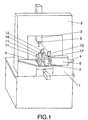
- the machine tool of the invention comprises a support (1), a traveling gantry (2) and a head (3), incorporating a platform (4) on which is mounted the majority of the components of the control system.
- a retro-reflector (5) which constitutes the only element mounted on a moving element of the machine.
- the control system As relates to the control system, as seen in the Figure 2, it comprises a laser emitter (6) that emits a beam which enters a polarization splitter (7) that separates the horizontal component (transmitted by the beam splitter (7) and known as the "measurement beam”) and the vertical component (reflected by the measurement beam and known as the "reference beam”), the reference beam passing through a quarter wave plate (8) to reach a fixed retro-reflector (9).
- the vertical component of the beam is reflected by the fixed retro-reflector (9), passes through the quarter wave plate (8) again and incides on the beam splitter (7) again, being transmitted by it to reach the receiver of the interferometer system (10).
- This beam serves as a comparative reference for the later measurement of the distance to the head which is performed by the interferometer combining this signal with that obtained by the measurement beam of the interferometer system, as described further below.
- the horizontal component of the measurement beam that has been transmitted by the beam splitter (7) passes through a quarter wave plate and a beam splitter (11) to incide on a plane mirror that deflects the beam towards the first deflecting mirror (12), which in turn deflects it towards a second deflecting mirror (13) that directs the beam to the retro-reflector (5) mounted on the head (3) of the machine tool.
- the reflected beam incides on a positional detection system(14) so that the data obtained by this detection system (14) are used to act on the deflecting mirrors (12) and (13), correcting their orientation so that the incidence on the detector (14) is always at a given position.
- This system will serve to calculate the orientation of the measurement beam and change the position of the head (3), following the previously programmed movement.
- the beam transmitted by the quarter wave plate incides on the polarisation beam splitter (7) and is reflected by it towards the receiver of the interferometer system (10).
- the reference beam which travels a constant distance in time
- the measurement beam that travels a distance that depends on the position of the retroreflecting mirror (5) anchored to the head (3), are combine to allow calculating the distance travelled by the retroreflecting mirror (5) in relation to a given reference position.
- the position detector comprises an opto-electronic sensor that can provide information on the position of a point of light that incides on its photosensitive surface; specifically, a matrix sensor is used that allows determining the position of the beam on the X and Y axes.
- the deviation values found by the position detector (14) are sent to the control system (15) which in turn uses them to send the corresponding commands to the motor (16) which positions the first mirror (12) and the motor (17) which positions the second mirror (13), so that the mirrors (12) and (13) are reoriented towards the true position of the head at all times.
- control system (15) uses the data from the mirror motor encoders and the value of the distance calculated by the interferometer (10) to estimate the XYZ coordinates of the machine head and sends the corresponding commands to the control system (15) of the machine tool to reposition the head in the correct location.
- galvanometric motors are used that allow an optical angular excursion of ⁇ 20°, with the axes of the motors placed perpendicular and separated by a certain distance so that they do not intersect.
- the optical aperture of the deflecting mirrors is 15 mm., so that they are light enough to allow a bandwidth of 2500 Hz.
- the materials, shape, size and arrangement of the elements may vary as long as the essence of the invention is not affected.
Landscapes
- Physics & Mathematics (AREA)
- General Physics & Mathematics (AREA)
- Engineering & Computer Science (AREA)
- Electromagnetism (AREA)
- Computer Networks & Wireless Communication (AREA)
- Radar, Positioning & Navigation (AREA)
- Remote Sensing (AREA)
- Manufacturing & Machinery (AREA)
- Automation & Control Theory (AREA)
- Human Computer Interaction (AREA)
- Machine Tool Sensing Apparatuses (AREA)
- Control Of Position Or Direction (AREA)
- Automatic Control Of Machine Tools (AREA)
- Length Measuring Devices By Optical Means (AREA)
Abstract
The machine tool incorporates a continuous control system which allows to control the position of the machine head (3) throughout its entire motion, and with the deviation data obtained acts on the machine servomotors to take the head (3) to its correct position. The control system comprises a laser emitter (6), a first deflecting mirror (12), a second deflecting mirror (13) and a retro-reflecting mirror (5), mounted on the machine head (3) with the particular characteristic that each of the two deflecting mirrors (12) and (13) has its own motor (16), (17) that allows to change its orientation independently as a function of the deviations found of the head (3). The system is complemented by an interferometer (10), a positional detection system (14) and a data acquisition and processing system (15), with the characteristic that all system elements with the exception of the retro-reflecting mirror (5) are placed on a platform (4) which is attached to the structure or support (1) of the machine in order to reduce the mass suspended on the moving elements and therefore undesired inertia. <IMAGE>
Description
The machine tool object of the invention incorporates a control system
which allows to control the position of a machine tool head as it moves along
its working trajectory, and in view of the deviation data obtained to act directly
on the numerical control of the machine to correct the head position during
the movement of the machine so that the head does not deviate from the
preset working trajectory.
The machine object of the invention incorporates a control system
which in addition to accurately determining the position of the head at each
instant allows a fast dynamic response of all its elements in order to act
quickly on the numerical control of the machine and thereby ensure that the
control can be continuous, and therefore that the machine does not stray
from the preset trajectory.
A machine tool consists of a traveling gantry which may move along
three rectilinear directions, and which holds a head which in turn holds the
corresponding revolving tool. These machines generally include a numerical
control system which is meant to make the head move along a preset
working trajectory, but in practice when precision work is performed it is usual
for maladjustments, wear and play to arise over time, so that it may be
necessary to recalibrate and tune the machine.
For this reason tracking systems have proliferated, generally
employing optical means, mainly meant to obtain accurate information on the
position of a moving object and which are used to calibrate the machine or
robot during its assembly, before its start up or during periodic check ups in
order to readjust them to make position deviations as small as possible.
These systems are also used as external means which allow to know
the position of the head, normally in robotic systems, at critical times or
positions of its work, in order to control head deviations so that when these
are excessive the machine is stopped and its position corrected.
Tracking and control optical systems for static or moving objects are
described for example in patents EP 1 001 251, US 4,714,339 and US
4,790,651.
Specifically, these systems generally consist of a laser gun emitting a
beam that reflects on a retroreflecting mirror provided on the moving object or
tool to be controlled. The beam returns to the gun after being reflected on a
directable mirror and incides on a photosensor that measures the position of
the beam along two axes to determine the deviation of the reflected beam.
These systems are also generally provided with an interferometer which
allows to determine the distance between the emitter and the receiver, so
that with the information of the rotations of the photosensor element and the
interferometer measurements the coordinates of the position of the object or
tool may be determined.
The measurement of the deviation detected by the photosensor is
used to redirect the mirror towards the new position of the tool so that it can
maintain its alignment for the following measurement.
These systems can be used therefore to find out the position of the
tool head to varying degrees of accuracy, but with the data obtained the
numerical control of the machine or robot must be acted upon and the
required position corrections entered. That is, the tracking system does not
interact with the machine but is simply an external system which may obtain
the spatial position of the machine head.
Obviously this type of operation implies stopping the machine, and
therefore position corrections can only be made at certain, generally critical,
points of the trajectory as otherwise stoppages would be constant and the
production rate would be unacceptably slow.
Also known is US Patent 4,621,926 relating to an interferometer
system for controlling the movement of an object along a predetermined
trajectory. This system incorporates three laser emitters which incide on two
mirrors attached to the machine head, employing three interferometers to
determine the three coordinates of the spatial position of the head. This
optical system determines the positions very accurately but lacks a fast
dynamic response which can act on the machine control system quickly
enough to allow a continuous control of the entire trajectory, so that this
system would be suitable for obtaining accurate information on the deviation
of the head but would not be suitable for acting on the head as it moves at
great speeds during the working operations of the tool. One must consider
that a miller head for example moves at speeds of up to 2 meters per
second.
For this reason, the control system will be actuated with the machine
stopped, so that these systems are valid for the initial calibration of the
machine or to adjust its position at the end of an operation or working cycle,
but not for real time control.
This lack of dynamic response is due among other reasons to the
masses hung from the various elements which must be moved or redirected
every time the tool position changes, such as on the head or on the mirror
itself, which increase the inertia of these moving elements preventing their
quick repositioning and therefore preventing a continuous actuation on the
machine.
Specifically, the mirror that deflects the beam between the emitter and
the header must be positionable and directable in two senses, so that it uses
two motors with their corresponding encoders and tachometers suspended
on the mirror, so that the mass of the assembly prevents a fast repositioning
of the mirror.
Additionally, on the machine head are mounted both the retro-reflecting
mirror or mirrors and the deviation detection elements, which on
one hand add an unnecessary and undesirable weight to the head and in
addition hinder their assembly and attachment on a head which is often
small, and more importantly have the disadvantage that the power supply
and control of the position detection card requires wiring the moving head,
with the resulting increased complexity of the machine.
The machine tool of the invention incorporates a control system based
on an optical system which can determine the position of the machine header
at all times and act immediately and continuously on the control system of
the machine in order to reposition the head to its correct position during the
motion of the head in its working cycle, thereby preventing deviations from
the preprogrammed working trajectory.
For this purpose, the optical system comprises a number of elements
which allow to quickly and accurately detect the head deviations so that it is
possible to act quickly on the control system of the machine.
Specifically, the optical system comprises a laser emitter mounted on
a platform that is attached to the machine, a retro-reflecting mirror placed on
the machine tool and two deflecting mirrors which deflect the laser beam
from the emitter to the retro-reflector mounted on the head, and vice versa.
One of the characteristics of the invention specifically relates to the
use of two independent deflecting mirrors mounted on an external platform of
the machine, and each provided with an independent motor for reorientation
towards the position of the retro-reflecting mirror.
The use of separate and independent mirrors allows each mirror to
have its own motor, so that the masses suspended from each mirror are
reduced and so the dynamic reorientation capacity is substantially improved,
allowing to measure and act on the machine much more quickly and to
correct the position of the head while the machine is working.
The first deflecting mirror can be oriented along an X-axis while the
second deflecting mirror can be oriented along a Y-axis, perpendicular to the
orientation axis of the other mirror.
In order to determine the deviations in the plane perpendicular to the
laser beam a two-dimensional position detection system (PDS) is used which
can detect movement on the surface of a beam, providing the coordinates of
said beam with respect to its center. This detection system is placed on an
external support so that it is not a mass suspended from the head or other
moving elements, thereby not affecting the dynamic performance of the
system and further allowing to eliminate the wires suspended on the head.
The control system also uses an interferometer which measures the
distance between the laser emitter and the tool head.
Finally, a control system is used which depending on the data from the
PDS, the mirror motor encoders and the interferometer measurements
calculates the positional deviation of the position of the head and instantly
acts on the motors of the first and second mirror, in order to reorient them
with respect to the new position of the head, and on the machine tool control
to move the head to the correct position without interrupting the operation of
the machine.
As indicated above the machine tool of the invention has the particular
characteristic that only the reflecting mirror is mounted on the machine head,
with all other components mounted on fixed supports or platforms, thereby
avoiding the external wiring used in other systems and the presence of
excessive weight on the head and mirrors.
The operation of the control system is as follows:
The laser emitter sends a beam which incides on the first deflecting
mirror so that the beam is sent towards the second deflecting mirror which in
turn sends it to the retro-reflecting mirror mounted on the machine head.
The beam is reflected by the retro-reflecting mirror inciding on the
second mirror, which deflects it to the first mirror and this mirror in turn sends
it to the PDS which determines the deviation of the reflected beam from the
emitted beam, along the X and Y axes.
The reflected beam is also made to pass through the interferometer,
which measures the interference bands between the emitted and reflected
beams, thereby calculating the distance between the tracking point and the
mirror on the head.
The data obtained from the position detection system and the
interferometer are entered in the machine control system which calculates
the real current position of the machine and comparing it to the expected
position determines the positional deviation. These data are communicated
directly to the machine control so that it acts on the machine servomotors,
positioning the tool point at the correct position.
Additionally, the measurements of deviation along the X and Y axes
are used to send corresponding commands to the positioning motors of the
first and second deflecting mirrors, so that they reorient themselves in view of
the real position of the head retro-reflector.
As a complement of the description being made and to aid a better
understanding of the characteristics of the invention, the present descriptive
memory is accompanied by a set of drawings which are an integral part of
the description and where for purposes of illustration only and in a nonlimiting
manner the following is shown:
The machine tool of the invention comprises a support (1), a traveling
gantry (2) and a head (3), incorporating a platform (4) on which is mounted
the majority of the components of the control system. On the head (3) is
mounted a retro-reflector (5) which constitutes the only element mounted on
a moving element of the machine.
As relates to the control system, as seen in the Figure 2, it comprises
a laser emitter (6) that emits a beam which enters a polarization splitter (7)
that separates the horizontal component (transmitted by the beam splitter (7)
and known as the "measurement beam") and the vertical component
(reflected by the measurement beam and known as the "reference beam"),
the reference beam passing through a quarter wave plate (8) to reach a fixed
retro-reflector (9). The vertical component of the beam is reflected by the
fixed retro-reflector (9), passes through the quarter wave plate (8) again and
incides on the beam splitter (7) again, being transmitted by it to reach the
receiver of the interferometer system (10). This beam serves as a
comparative reference for the later measurement of the distance to the head
which is performed by the interferometer combining this signal with that
obtained by the measurement beam of the interferometer system, as
described further below.
The horizontal component of the measurement beam that has been
transmitted by the beam splitter (7) passes through a quarter wave plate and
a beam splitter (11) to incide on a plane mirror that deflects the beam
towards the first deflecting mirror (12), which in turn deflects it towards a
second deflecting mirror (13) that directs the beam to the retro-reflector (5)
mounted on the head (3) of the machine tool.
The beam reflected by the retroreflector (5) again incides on the
second deflecting mirror (13), is deflected towards the first deflecting mirror
(12) which directs it towards the plane mirror, from where it incides on the
beam splitter (11) and on the quarter wave plate, where the beam is divided
into a reflected and a transmitted part.
The reflected beam incides on a positional detection system(14) so
that the data obtained by this detection system (14) are used to act on the
deflecting mirrors (12) and (13), correcting their orientation so that the
incidence on the detector (14) is always at a given position. This system
will serve to calculate the orientation of the measurement beam and change
the position of the head (3), following the previously programmed
movement.
The beam transmitted by the quarter wave plate incides on the
polarisation beam splitter (7) and is reflected by it towards the receiver of
the interferometer system (10).
At the interferometer receiver (10) the reference beam, which travels a
constant distance in time, and the measurement beam, that travels a
distance that depends on the position of the retroreflecting mirror (5)
anchored to the head (3), are combine to allow calculating the distance
travelled by the retroreflecting mirror (5) in relation to a given reference
position.
The position detector (PDS) comprises an opto-electronic sensor that
can provide information on the position of a point of light that incides on its
photosensitive surface; specifically, a matrix sensor is used that allows
determining the position of the beam on the X and Y axes.
The deviation values found by the position detector (14) are sent to
the control system (15) which in turn uses them to send the corresponding
commands to the motor (16) which positions the first mirror (12) and the
motor (17) which positions the second mirror (13), so that the mirrors (12)
and (13) are reoriented towards the true position of the head at all times.
In addition, the control system (15) uses the data from the mirror
motor encoders and the value of the distance calculated by the
interferometer (10) to estimate the XYZ coordinates of the machine head and
sends the corresponding commands to the control system (15) of the
machine tool to reposition the head in the correct location.
As shown in figure 2, only the retro-reflector (5) is mounted on the
machine head, while all other components are mounted on a fixed platform
(4) in order to greatly reduce the masses suspended from the moving
elements, such as from the head, which naturally improves the dynamic
performance of the system.
For this reason, also important is the use of two independent and
separate deflecting mirrors (12), each of which can be directed along a
different axis and positioned by different independent motors (16) and (17),
so that each motor must only carry its corresponding mirror and thereby
providing a fast response capability so that the system can be controlled
continuously.
Specifically, galvanometric motors are used that allow an optical
angular excursion of ± 20°, with the axes of the motors placed perpendicular
and separated by a certain distance so that they do not intersect.
The optical aperture of the deflecting mirrors is 15 mm., so that they
are light enough to allow a bandwidth of 2500 Hz.
It is not considered necessary to extend this description for an expert
in the field to understand the scope of the invention and the advantages
derived thereof.
The materials, shape, size and arrangement of the elements may vary
as long as the essence of the invention is not affected.
Claims (1)
- Machine tool with continuous positional control, comprising a support (1), a traveling gantry (2) and a directable head (3) which moves the working tool, characterized in that it incorporates:with the particular characteristic that the retro-reflecting mirror (5) is mounted on the machine head (3) while all other components are mounted on a platform (4) which is attached to the support or structure (1) of the machine.A laser emitter (6), mounted on a platform (4) joined to the support (1) of the machine, which emits a laser beam towardsa retro-reflecting mirror (5) mounted on the head (3) of the tool,a first deflecting mirror (12), which deflects the laser beam and incorporates a motor (16) that allows to move the mirror along an X axis,a second deflecting mirror (13), which deflects the laser beam and incorporates a motor (17) that allows to move the mirror along a Y axis,a positional detector (14) placed outside the machine head (3), which determines the deviation of the beams reflected by the first and second deflecting mirrors (12) and (13), in a plane perpendicular to the laser beam.an interferometer (10) which measures the distance between the laser emitter (6) and the retro-reflecting mirror (5) mounted on the tool head (3),a control system (15) which, depending on the values obtained from the position detector (14), of the mirror motor encoders (16) and (17) of the mirrors (12) and (13) and the measurement of the interferometer (10), calculates the deviations of the position of the head (3) and instantaneously acts on:the motor (16) of the first deflecting mirror (12) and the motor (17) of the second deflecting mirror (13), to reorient them with respect to the new position of the head (3) andon the machine control in order to move the head (3) to the correct position, during the motion of the machine itself,
Applications Claiming Priority (3)
| Application Number | Priority Date | Filing Date | Title |
|---|---|---|---|
| ES200200344A ES2190901B1 (en) | 2002-02-13 | 2002-02-13 | MACHINE-TOOL WITH CONTINUOUS POSITION REGULATION. |
| ES200200344 | 2002-02-13 | ||
| PCT/ES2003/000079 WO2003069417A1 (en) | 2002-02-13 | 2003-02-13 | Machine-tool with continuous position adjustment |
Publications (1)
| Publication Number | Publication Date |
|---|---|
| EP1486837A1 true EP1486837A1 (en) | 2004-12-15 |
Family
ID=27675920
Family Applications (1)
| Application Number | Title | Priority Date | Filing Date |
|---|---|---|---|
| EP03704720A Ceased EP1486837A1 (en) | 2002-02-13 | 2003-02-13 | Machine-tool with continuous position adjustment |
Country Status (4)
| Country | Link |
|---|---|
| EP (1) | EP1486837A1 (en) |
| AU (1) | AU2003206980A1 (en) |
| ES (1) | ES2190901B1 (en) |
| WO (1) | WO2003069417A1 (en) |
Family Cites Families (3)
| Publication number | Priority date | Publication date | Assignee | Title |
|---|---|---|---|---|
| JPH0621902B2 (en) * | 1985-04-19 | 1994-03-23 | 日本電気株式会社 | Beam positioner |
| US4714339B2 (en) * | 1986-02-28 | 2000-05-23 | Us Commerce | Three and five axis laser tracking systems |
| US5646765A (en) * | 1994-10-05 | 1997-07-08 | Synrad, Inc. | Laser scanner |
-
2002
- 2002-02-13 ES ES200200344A patent/ES2190901B1/en not_active Expired - Fee Related
-
2003
- 2003-02-13 AU AU2003206980A patent/AU2003206980A1/en not_active Abandoned
- 2003-02-13 EP EP03704720A patent/EP1486837A1/en not_active Ceased
- 2003-02-13 WO PCT/ES2003/000079 patent/WO2003069417A1/en not_active Ceased
Non-Patent Citations (1)
| Title |
|---|
| See references of WO03069417A1 * |
Also Published As
| Publication number | Publication date |
|---|---|
| WO2003069417A1 (en) | 2003-08-21 |
| AU2003206980A1 (en) | 2003-09-04 |
| ES2190901B1 (en) | 2005-09-16 |
| ES2190901A1 (en) | 2003-08-16 |
Similar Documents
| Publication | Publication Date | Title |
|---|---|---|
| EP3669138B1 (en) | Laser tracker with improved roll angle measurement | |
| KR101906942B1 (en) | Calibration of a coordinate measuring machine using a calibration laser head at the tool centre point | |
| US4788440A (en) | Electro-optical systems for control of robots, manipulator arms and coordinate measuring machines | |
| CA2817033C (en) | Rotating laser | |
| US8199316B2 (en) | Device and method for tracking the movement of a tool of a handling unit | |
| CN112424563A (en) | Multi-dimensional measurement system for accurately calculating position and orientation of dynamic object | |
| US4882848A (en) | Probe head for a coordinate-measuring instrument | |
| EP3584533A1 (en) | Coordinate measurement system | |
| CA2732312A1 (en) | System and method for precise real-time control of position and orientation of tooling | |
| CN114248154A (en) | Five-axis machine tool space positioning precision detection device and method | |
| US5146290A (en) | Process and apparatus for determining the position of an object | |
| JP2014513792A (en) | Measuring system for determining 3D coordinates of the surface of an object | |
| US10935968B2 (en) | Robot, robot system, and method for setting coordinate system of robot | |
| CN116878788A (en) | Deflection measuring device and method for full-size test of component | |
| JP2001153632A (en) | Method and device for detecting medical object, especially model of tooth specimen | |
| US4941739A (en) | Mirror scanner | |
| CN114509004B (en) | Measuring method and measuring device based on machine vision | |
| WO2003069417A1 (en) | Machine-tool with continuous position adjustment | |
| WO2022259538A1 (en) | Position-measuring device, position-measuring system, and measuring device | |
| JPH0467602B2 (en) | ||
| JPS5922104A (en) | Method and device for controlling movable arm of robot | |
| JP2501234B2 (en) | Position detection device for self-propelled construction work machine | |
| JPS62259011A (en) | Distance detector | |
| JPH06285747A (en) | Original point setting method for composite work machine and corrected value setting method to correct position coordinate | |
| JPH02309207A (en) | Method and apparatus for detecting angular displacement of robot arm shaft |
Legal Events
| Date | Code | Title | Description |
|---|---|---|---|
| PUAI | Public reference made under article 153(3) epc to a published international application that has entered the european phase |
Free format text: ORIGINAL CODE: 0009012 |
|
| 17P | Request for examination filed |
Effective date: 20040909 |
|
| AK | Designated contracting states |
Kind code of ref document: A1 Designated state(s): AT BE BG CH CY CZ DE DK EE ES FI FR GB GR HU IE IT LI LU MC NL PT SE SI SK TR |
|
| AX | Request for extension of the european patent |
Extension state: AL LT LV MK RO |
|
| STAA | Information on the status of an ep patent application or granted ep patent |
Free format text: STATUS: THE APPLICATION HAS BEEN REFUSED |
|
| 18R | Application refused |
Effective date: 20070803 |