EP1486812A2 - Dark field illumination device - Google Patents
Dark field illumination device Download PDFInfo
- Publication number
- EP1486812A2 EP1486812A2 EP04013651A EP04013651A EP1486812A2 EP 1486812 A2 EP1486812 A2 EP 1486812A2 EP 04013651 A EP04013651 A EP 04013651A EP 04013651 A EP04013651 A EP 04013651A EP 1486812 A2 EP1486812 A2 EP 1486812A2
- Authority
- EP
- European Patent Office
- Prior art keywords
- illumination light
- sample
- light rays
- dark field
- illumination
- Prior art date
- Legal status (The legal status is an assumption and is not a legal conclusion. Google has not performed a legal analysis and makes no representation as to the accuracy of the status listed.)
- Granted
Links
Images


Classifications
-
- G—PHYSICS
- G02—OPTICS
- G02B—OPTICAL ELEMENTS, SYSTEMS OR APPARATUS
- G02B27/00—Optical systems or apparatus not provided for by any of the groups G02B1/00 - G02B26/00, G02B30/00
- G02B27/0006—Optical systems or apparatus not provided for by any of the groups G02B1/00 - G02B26/00, G02B30/00 with means to keep optical surfaces clean, e.g. by preventing or removing dirt, stains, contamination, condensation
-
- G—PHYSICS
- G02—OPTICS
- G02B—OPTICAL ELEMENTS, SYSTEMS OR APPARATUS
- G02B1/00—Optical elements characterised by the material of which they are made; Optical coatings for optical elements
- G02B1/10—Optical coatings produced by application to, or surface treatment of, optical elements
- G02B1/11—Anti-reflection coatings
-
- G—PHYSICS
- G02—OPTICS
- G02B—OPTICAL ELEMENTS, SYSTEMS OR APPARATUS
- G02B21/00—Microscopes
- G02B21/06—Means for illuminating specimens
- G02B21/08—Condensers
- G02B21/10—Condensers affording dark-field illumination
Definitions
- the present invention relates to a dark field illumination device of a microscope.
- the dark field observation is a method of observing only scattered light from the sample by preventing illumination light from directly entering observation optical system, so that, in an observed image, only the scattered light can be seen in the darkness.
- FIG. 5 shows a sectional configuration of the illumination device for performing the dark field observation disclosed in this document.
- a switch lever 22 for bright field/dark field is placed above an illumination light source 18 during dark field observation. This shields only the illumination light rays directly entering the observation optical system among the illumination light rays emitted from the illumination light source 18. Other illumination light rays are reflected toward a sample 30 by an inner surface of a reflecting mirror, and illuminate the sample 30.
- a light shielding portion 31 is disposed to prevent the light rays in light paths other than the originally designed light paths from entering the observation optical system.
- the unnecessary reflected illumination light rays that have penetrated the sample 30 moves upward in the drawing without entering the observation optical system.
- the dark field observation can be achieved in which only the scattered light of the observed image can be seen in the dark field.
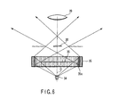
- FIG. 6 shows a sectional configuration of the illumination device for performing the dark field observation disclosed in this document.
- a light shielding portion 36 is disposed between an illumination light source 34 and an objective lens 39 as the observation optical system.
- the light shielding portion 36 only shields illumination the light rays directly entering the objective lens 39 among the illumination light rays emitted from the illumination light source 34.
- Other illumination light rays are reflected toward a sample 38 by an inner wall surface 35a formed inside a reflecting mirror 35, and illuminate the sample 38.
- the disadvantageous reflected illumination light rays that have penetrated the sample 38 moves upward in the drawing without entering the objective lens 39.
- the dark field observation is achieved in which only the scattered light of the observed image can be seen in the darkness.
- the sample is held with a glass plate or a glass container.
- a dustproof waterproof glass to prevent entrance of dust and water into the illumination device is provided between the sample and a light shielding plate.
- a glass member is generally present between the sample and the illumination light source. Therefore, part of the illumination light rays that illuminate the sample is again reflected toward the illumination light source by the glass surface. Part of the reflected light rays falls on the light shielding plate and is diffused, and part of the diffused light enters the objective lens to decrease the contrast of the observed image.
- the present invention is directed to a dark field illumination device to provide dark field illumination to a sample to be observed by observation optical system.
- the dark field illumination device of the present invention comprises an illumination light source, which emits illumination light rays, a light shielding plate, which is located between the sample and the illumination light source, and selectively shields the illumination light rays directly entering the observation optical system among the illumination light rays emitted from the illumination light source, an optical member, which directs, toward the sample, the illumination light rays passing outside the illumination light rays shielded by the light shielding plate, and a background member, which is disposed between the sample and the light shielding plate, and has a smooth surface on a side of the sample.
- FIG. 1 shows a sectional configuration of the dark field illumination device in a first embodiment of the present invention.
- a sample 7 is mounted on a stage glass 5.
- the observation optical system to observe the sample 7 includes, for example, an objective lens 6 of a microscope.
- the objective lens 6 is disposed above the sample 7.
- the dark field illumination device of the present embodiment is located on the opposite side of the objective lens 6 of the observation optical system with reference to the stage glass 5, that is, located below the stage glass 5.
- the dark field illumination device of the present embodiment comprises an illumination light source 1, which emits illumination light rays, a light shielding plate 3, which shields part of the illumination light rays emitted from the illumination light source 1, an absorption-type ND filter 4 (a light transmittance of 20% or lower), and a cylindrical dark field mirror 2 surrounding the light shielding plate 3 and the ND filter 4.
- the illumination light source 1, the light shielding plate 3 and the ND filter 4 are all located on an optical axis O of the objective lens 6.
- the light shielding plate 3 is located between the sample 7 and the illumination light source 1, and selectively shields the illumination light rays directly entering the objective lens 6 among the illumination light rays emitted from the illumination light source 1.
- the cylindrical dark field mirror 2 has its inside diameter larger than the light shielding plate 3 and the ND filter 4, and its inner surface 2a is a mirror and directs, toward the sample 7, the illumination light rays passing outside the illumination light rays shielded by the light shielding plate 3 (i.e., reflects them toward the sample 7).
- the illumination light rays are equally applied to the sample 7 from its periphery.
- the ND filter 4 is disposed between the sample 7 and the light shielding plate 3, and has a smooth surface 4a on the side of the sample 7.
- the illumination light rays directly heading to the sample 7 are shielded by the light shielding plate 3, and can not reach the sample 7. Further, the illumination light rays L1 reflected by the inner surface 2a of the dark field mirror 2 pass outside the ND filter 4 and penetrate the stage glass 5. Part of the illumination light rays L1 strikes on the sample 7, while the rest escape out of a microscope device without entering the objective lens 6 of the observation optical system. The illumination light rays L1 struck on the sample 7 illuminate the sample 7, and are scattered at the sample 7.
- the light shielding plate 3 shields the light of the illumination light source 1, so that a magnified and viewed field of the observation optical system will have a dark background, and thus the scattered light from the sample 7 is observed in the dark background.
- the illumination light rays L1 reflected by the dark field mirror 2 1 - 5 percent is reflected on a surface of the stage glass 5 that is on the side of the illumination light source 1 and on a surface that is on the side of the sample 7.
- the illumination light rays L2 reflected by the stage glass 5 mostly enter the ND filter 4. Since a surface of the ND filter 4 on the side of the sample 7 is the smooth surface 4a, the illumination light rays L2 entering the ND filter 4 are hardly scattered on the surface of the ND filter 4 that is on the side of the sample 7, i.e., the smooth surface 4a.
- the illumination light rays L2 that have entered the ND filter 4 mainly penetrate the smooth surface 4a without being scattered and enter the ND filter 4, and are then sufficiently attenuated due to light absorption of the ND filter 4. Moreover, roughly 1 - 10 percent of the illumination light rays L2 that have entered the ND filter 4 is reflected on the smooth surface 4a and therefore does not pass through the smooth surface 4a to enter the ND filter 4. However, such illumination light rays L3 are reflected without being scattered on the smooth surface 4a, pass outside (the aperture of) the objective lens 6, and escape out of the microscope device.
- the dark field illumination device of the present embodiment because the ND filter 4 has the smooth surface 4a on the side of the sample, the illumination light rays L2 reflected by the stage glass 5 enter the ND filter 4 and are then absorbed by the ND filter 4 without being scattered, or are reflected by the smooth surface 4a to escape out of the observation optical system. As a result, undesired light rays are effectively prevented from entering the observation optical system. This enables dark field observation with the dark background and satisfactory contrast. Therefore, according to the present embodiment, the dark field illumination device that enables the dark field observation with the satisfactory contrast without being affected by improvement of brightness of illumination light is provided.
- the ND filter 4 can be easily disposed near the light shielding plate 3 without any problem, and can therefore be compactly built along the optical axis.
- stage glass 5 can be removed, and the smooth surface 4a of the absorption-type ND filter 4 can be easily cleaned, so that optically diffused objects such as dust and stains sticking to the smooth surface 4a of the ND filter 4 can be easily removed. It is thus possible to successively obtain the dark field observation with the dark background and satisfactory contrast.
- the absorption-type ND filter 4 in the dark field illumination device of the present embodiment may be replaced with an interference-type ND filter having a smooth surface on the side of the sample 7.
- the interference-type ND filter has a light transmittance of, for example, 20% or lower.
- An interference film of the interference-type ND filter may be formed either on a surface on the side of the sample 7 or a surface on the side of the illumination light source 1.
- the illumination light rays L2 that have fallen on the interference-type ND filter are hardly scattered because the interference-type ND filter has the smooth surface on the side of the sample 7.
- the illumination light rays that have entered the interference-type ND filter repeat interference and are attenuated. Further, the illumination light rays reflected by the interference-type ND filter escape out of the objective lens 6.
- the absorption-type ND filter 4 in the dark field illumination device of the present embodiment may be replaced with a light absorbing member, which has a smooth surface on the side of the sample 7, and attenuates light by absorbing it.
- the light absorbing member may comprise an acrylic plate or a window film, for example, having a light transmittance of 0% to 20%.
- the illumination light rays L2 that have fallen on the light absorbing member are hardly scattered because the light absorbing member has the smooth surface on the side of the sample 7.
- the illumination light rays that have entered the light absorbing member are absorbed and attenuated. Further, the illumination light rays reflected by the light absorbing member escape out of the objective lens 6.
- the absorption-type ND filter 4 in the dark field illumination device of the present embodiment may be replaced with a mirror having a smooth mirror surface on the side of the sample 7.
- the smooth surface may be the mirror surface.
- the illumination light rays L2 that have fallen on the mirror are hardly scattered because the mirror has the smooth surface on the side of the sample 7.
- the illumination light rays that have fallen on the mirror are reflected and escape out of the objective lens 6.
- the ND filter (and its substitute members) in the dark field illumination device of the present embodiment may further have an anti-reflection film provided on the smooth surface.
- the illumination light rays L2 that have fallen on the smooth surface enter the anti-reflection film and are attenuated by interference. This reduces the amount of illumination light rays reflected by the smooth surface. Moreover, the illumination light rays that have entered the ND filter or the like are more suitably absorbed.
- the absorption-type ND filter 4 in the dark field illumination device of the present embodiment may be replaced with a hair transplant cloth.
- the hair transplant cloth is a cloth in which countless numbers of hairs are vertically transplanted, and the hair itself has a low reflectance, and the countless numbers of hairs have parts where they overlap each other. Therefore, the hair transplant cloth hardly scatters and reflects the fallen light.
- the illumination light rays fallen on the hair transplant cloth are hardly scattered and hardly reflected.
- FIG. 2 shows a sectional configuration of the dark field illumination device in a second embodiment of the present invention.
- members indicated by the same reference numerals as the members shown in FIG. 1 are similar members, and will not be described in detail.
- the dark field illumination device of the present embodiment further comprises a dustproof waterproof glass 8, which is disposed between the dark field mirror 2 and the stage glass 5, in addition to the configuration of the dark field illumination device in the first embodiment. While the stage glass 5 can be removed, the dustproof waterproof glass 8 is fixed to a main body of a microscope illumination stand and prevents pollutants such as dust and water from entering the illumination stand main unit.
- the dustproof waterproof glass 8 reflects part of the illumination light rays L1 reflected by an inner surface 28 of the dark field mirror 2. Part of the illumination light rays L4 reflected by the dustproof waterproof glass 8 falls on the ND filter 4 (and its substitute members). The illumination light rays L4 that have fallen on the ND filter (and its substitute members) are hardly scattered because the ND filter 4 (and its substitute members) has the smooth surface on the side of the sample 7. The illumination light rays L5 reflected by the ND filter 4 (and its substitute members) escape out of the objective lens 6. Further, the illumination light rays that have entered the ND filter 4 (and its substitute members except for the mirror) are attenuated.
- the dark field illumination device of the present embodiment has the dustproof waterproof glass 8 in addition to the same advantage as in the first embodiment, so that stains on the ND filter 4 (and its substitute members) are effectively prevented.
- the dustproof waterproof glass 8 in the dark field illumination device of the present embodiment may further have an anti-reflection film provided on its surface.
- the dustproof waterproof glass 8 has the anti-reflection film, the amount of illumination light rays reflected toward the illumination light source 1 by the dustproof waterproof glass 8 is reduced.
- the dustproof waterproof glass 8 in the dark field illumination device of the present embodiment may be replaced with various kinds of optical members. Moreover, such various kinds of optical members may be disposed between the ND filter 4 (and its substitute members) and the stage glass 5.
- the present embodiment is directed to partial modifications of the dark field illumination device of the first embodiment and the dark field illumination device of the second embodiment.
- the dark field illumination device of the present embodiment has a configuration in which the light shielding plate 3 is removed from the configuration of the dark field illumination device of the first embodiment and the dark field illumination device of the second embodiment, but the ND filter 4 (and its substitute members) has the same function as the light shielding plate 3 instead.
- the light shielding plate and the ND filter (and its substitute members) constitute one component.
- the ND filter (and its substitute members) in the present embodiment has a light transmittance of 0% with respect to the illumination light from the side of the illumination light source 1.
- the ND filter (and its substitute members) also serves as the light shielding plate, it is possible to obtain such advantages as a reduction in the number of components, a reduction in component prices and a reduction in the number of assembly processes, as compared with the first embodiment and the second embodiment.
- FIG. 3 shows a sectional configuration of the dark field illumination device in a fourth embodiment of the present invention.
- FIG. 4 is a plan view of the dark field mirror shown in FIG. 3 viewed from below.
- members indicated by the same reference numerals as the members shown in FIG. 2 are similar members, and will not be described in detail.
- the dark field illumination device of the present embodiment comprises an illumination light source 9, which emits a bundle of illumination light rays, a collector lens 10, which converts the bundle of illumination light rays from the illumination light source 9 into a parallel bundle of light rays, a convex lens 12, which converts the parallel bundle of light rays into a converging bundle of light rays, various filters 11, which are disposed between the collector lens 10 and the convex lens 12, a mirror 13, which reflects the bundle of illumination light rays from the convex lens 12, and a dark field mirror 15.
- the dark field mirror 15 has a conical reflecting mirror 15a, a cylindrical mirror portion 15b whose inner surface is a mirror, and a link portion 15c linking the conical reflecting mirror 15a and the cylindrical mirror portion 15b.
- the conical reflecting mirror 15a directs the illumination light rays from the mirror 13 toward the cylindrical mirror portion 15b
- the cylindrical mirror portion 15b directs the illumination light rays from the conical reflecting mirror 15a toward the sample 7.
- the dark field illumination device further has a light shielding plate 17 for preventing the illumination light rays from the mirror 13 and the like from directly entering the objective lens 6.
- the light shielding plate 17 is provided on a rear side of the conical reflecting mirror 15a, that is, on the side of the sample.
- the dark field illumination device of the present embodiment has the same advantage as in the first to third embodiments, and in addition, the illumination light source 9 is disposed laterally off the optical axis O of the observation optical system, thereby allowing a reduction of size along the optical axis O. Further, as the illumination light source 9 is away from the sample 7, undesired temperature increase of the sample 7 can be effectively prevented.
Landscapes
- Physics & Mathematics (AREA)
- General Physics & Mathematics (AREA)
- Optics & Photonics (AREA)
- Chemical & Material Sciences (AREA)
- Analytical Chemistry (AREA)
- Microscoopes, Condenser (AREA)
Abstract
Description
Claims (11)
- A dark field illumination device to provide dark field illumination to a sample (7) to be observed by observation optical system (6), the device characterized by comprising:an illumination light source (1, 9), which emits illumination light rays;a light shielding plate (3, 17), which is located between the sample (7) and the illumination light source (1, 9), and selectively shields the illumination light rays directly entering the observation optical system (6) among the illumination light rays emitted from the illumination light source (1, 9);an optical member (2, 15), which directs, toward the sample (7), the illumination light rays passing outside the illumination light rays shielded by the light shielding plate (3, 17); anda background member (4), which is disposed between the sample (7) and the light shielding plate (3, 17), and has a smooth surface (4a) on a side of the sample (7).
- The device according to claim 1, characterized in that the smooth surface (4a) of the background member (4) is a mirror surface.
- The device according to claim 1, characterized in that the background member (4) attenuates the illumination light rays that have entered the background member (4).
- The device according to claim 3, characterized in that the background member (4) attenuates by absorption the illumination light rays that have entered the background member (4).
- The device according to claim 3, characterized in that the background member (4) attenuates by interference the illumination light rays that have entered the background member (4).
- The device according to claim 1, characterized in that the background member (4) further has an anti-reflection film provided on the smooth surface (4a).
- The device according to claim 3, characterized in that the background member (4) further has an anti-reflection film provided on the smooth surface (4a).
- The device according to any one of claim 1 to claim 7, characterized in that the optical member (2, 15) includes a cylindrical mirror (2a, 15b) whose inner surface is a reflective surface, and a central axis of the cylindrical mirror (2a, 15b) is generally coincident with an optical axis of the observation optical system (6).
- The device according to any one of claim 1 to claim 7, characterized in that the background member (4) and the light shielding plate (3, 17) constitute one component.
- The device according to claim 1, characterized by further comprising a dustproof waterproof glass (8) provided between the sample (7) and the background member (4).
- The device according to claim 10, characterized in that the dustproof waterproof glass (8) further has an anti-reflection film provided on its surface.
Applications Claiming Priority (2)
| Application Number | Priority Date | Filing Date | Title |
|---|---|---|---|
| JP2003168079A JP2005003995A (en) | 2003-06-12 | 2003-06-12 | Dark-field illuminator |
| JP2003168079 | 2003-06-12 |
Publications (3)
| Publication Number | Publication Date |
|---|---|
| EP1486812A2 true EP1486812A2 (en) | 2004-12-15 |
| EP1486812A3 EP1486812A3 (en) | 2005-02-23 |
| EP1486812B1 EP1486812B1 (en) | 2009-03-18 |
Family
ID=33296878
Family Applications (1)
| Application Number | Title | Priority Date | Filing Date |
|---|---|---|---|
| EP04013651A Expired - Lifetime EP1486812B1 (en) | 2003-06-12 | 2004-06-09 | Dark field illumination device |
Country Status (4)
| Country | Link |
|---|---|
| US (1) | US6989925B2 (en) |
| EP (1) | EP1486812B1 (en) |
| JP (1) | JP2005003995A (en) |
| DE (1) | DE602004020020D1 (en) |
Cited By (1)
| Publication number | Priority date | Publication date | Assignee | Title |
|---|---|---|---|---|
| WO2011144212A1 (en) * | 2010-05-21 | 2011-11-24 | Chemometec A/S | A compact dark field light source and dark field image analysis at low magnification |
Families Citing this family (5)
| Publication number | Priority date | Publication date | Assignee | Title |
|---|---|---|---|---|
| KR101324015B1 (en) * | 2011-08-18 | 2013-10-31 | 바슬러 비전 테크놀로지스 에이지 | Apparatus and method for detecting the surface defect of the glass substrate |
| US9885878B2 (en) * | 2013-04-10 | 2018-02-06 | Fei Efa, Inc. | Apparatus and method for annular optical power management |
| US11385452B2 (en) | 2015-03-13 | 2022-07-12 | Genea Ip Holdings Pty Limited | Method and apparatus for microscopy |
| WO2018017575A2 (en) * | 2016-07-18 | 2018-01-25 | Instrumental, Inc. | Modular optical inspection station |
| US12613403B2 (en) * | 2018-09-13 | 2026-04-28 | University Of Massachusetts | System and methods of dichroic free fluorescence illumination using reflective objective lenses |
Family Cites Families (12)
| Publication number | Priority date | Publication date | Assignee | Title |
|---|---|---|---|---|
| US2415732A (en) * | 1944-05-19 | 1947-02-11 | Domingo Emil | Microscope condenser |
| JPS503355A (en) * | 1973-05-11 | 1975-01-14 | ||
| JPS6090319A (en) * | 1983-10-24 | 1985-05-21 | Olympus Optical Co Ltd | Dark field illuminating device |
| DE3527322A1 (en) * | 1985-07-31 | 1987-02-12 | Zeiss Carl Fa | AUTOFOCUS DEVICE FOR LIGHTING MICROSCOPE |
| US5268749A (en) * | 1991-07-26 | 1993-12-07 | Kollmorgen Corporation | Apparatus and method for providing uniform illumination of a sample plane |
| US5820250A (en) * | 1995-10-24 | 1998-10-13 | Dolan-Jenner Industries, Inc. | Dark field illuminator ringlight adaptor |
| US5741213A (en) * | 1995-10-25 | 1998-04-21 | Toa Medical Electronics Co., Ltd. | Apparatus for analyzing blood |
| US5982534A (en) * | 1997-06-18 | 1999-11-09 | The Regents Of The University Of California | Specimen illumination apparatus with optical cavity for dark field illumination |
| JPH11153755A (en) | 1997-09-19 | 1999-06-08 | Olympus Optical Co Ltd | Dark field illuminator |
| JP2000019411A (en) * | 1998-07-02 | 2000-01-21 | Olympus Optical Co Ltd | Illuminator for stereoscopic microscope |
| CA2243090A1 (en) | 1998-07-10 | 2000-01-10 | Timothy M. Richardson | Inverted darkfield contrast microscope and method |
| JP4604300B2 (en) * | 2000-02-09 | 2011-01-05 | 株式会社ニコン | microscope |
-
2003
- 2003-06-12 JP JP2003168079A patent/JP2005003995A/en active Pending
-
2004
- 2004-06-04 US US10/861,813 patent/US6989925B2/en not_active Expired - Lifetime
- 2004-06-09 DE DE602004020020T patent/DE602004020020D1/en not_active Expired - Lifetime
- 2004-06-09 EP EP04013651A patent/EP1486812B1/en not_active Expired - Lifetime
Cited By (2)
| Publication number | Priority date | Publication date | Assignee | Title |
|---|---|---|---|---|
| WO2011144212A1 (en) * | 2010-05-21 | 2011-11-24 | Chemometec A/S | A compact dark field light source and dark field image analysis at low magnification |
| US9224031B2 (en) | 2010-05-21 | 2015-12-29 | Chemometec A/S | Compact dark field light source and dark field image analysis at low magnification |
Also Published As
| Publication number | Publication date |
|---|---|
| JP2005003995A (en) | 2005-01-06 |
| DE602004020020D1 (en) | 2009-04-30 |
| EP1486812A3 (en) | 2005-02-23 |
| EP1486812B1 (en) | 2009-03-18 |
| US20040252372A1 (en) | 2004-12-16 |
| US6989925B2 (en) | 2006-01-24 |
Similar Documents
| Publication | Publication Date | Title |
|---|---|---|
| US7855353B2 (en) | Vehicle window camera arrangement having camera with camera portions handling separate image and intensity acquisition functions using same light-guiding element portion | |
| EP0857316B1 (en) | Dark field illuminator ringlight adaptor | |
| US4737022A (en) | Automatic focusing device for reflected light microscopes | |
| US6924930B2 (en) | Microscope illumination device | |
| US8390926B2 (en) | High speed acquisition vision system and method for selectively viewing object features | |
| JP3872871B2 (en) | Objective lens and microscope | |
| WO2017005153A1 (en) | Anti-glare light-equalizing light source and image capturing device having same | |
| CN109791275A (en) | Observe device | |
| EP1486812B1 (en) | Dark field illumination device | |
| US8138476B2 (en) | Refraction assisted illumination for imaging | |
| JPH0516567B2 (en) | ||
| US7667210B2 (en) | Wide-area fluorescence detection system for multi-photon microscopy | |
| JP4493119B2 (en) | UV microscope | |
| JPH095663A (en) | Stray light removal device for coaxial irradiation imaging device | |
| JPS63142239A (en) | Apparatus for observing surface shape | |
| JP3908022B2 (en) | Fluorescence observation equipment | |
| JP2003177325A (en) | Total reflection fluorescence microscope | |
| JP2002214534A (en) | Illuminator and infrared microscope having illuminator | |
| JPH0972823A (en) | Optical member inspection device | |
| JP3434064B2 (en) | Epi-illumination phase contrast microscope | |
| JP2006330359A (en) | Microscope system and flare preventing optical apparatus | |
| JP2009086392A (en) | Phase contrast microscope | |
| KR940007343Y1 (en) | Microscope | |
| CA2051644A1 (en) | Camera Attachment System and Illuminating System for Microscope | |
| JP2008170873A (en) | Microscope lens barrel |
Legal Events
| Date | Code | Title | Description |
|---|---|---|---|
| PUAI | Public reference made under article 153(3) epc to a published international application that has entered the european phase |
Free format text: ORIGINAL CODE: 0009012 |
|
| AK | Designated contracting states |
Kind code of ref document: A2 Designated state(s): AT BE BG CH CY CZ DE DK EE ES FI FR GB GR HU IE IT LI LU MC NL PL PT RO SE SI SK TR |
|
| AX | Request for extension of the european patent |
Extension state: AL HR LT LV MK |
|
| PUAL | Search report despatched |
Free format text: ORIGINAL CODE: 0009013 |
|
| AK | Designated contracting states |
Kind code of ref document: A3 Designated state(s): AT BE BG CH CY CZ DE DK EE ES FI FR GB GR HU IE IT LI LU MC NL PL PT RO SE SI SK TR |
|
| AX | Request for extension of the european patent |
Extension state: AL HR LT LV MK |
|
| 17P | Request for examination filed |
Effective date: 20050530 |
|
| AKX | Designation fees paid |
Designated state(s): CH DE LI |
|
| 17Q | First examination report despatched |
Effective date: 20060302 |
|
| GRAP | Despatch of communication of intention to grant a patent |
Free format text: ORIGINAL CODE: EPIDOSNIGR1 |
|
| GRAS | Grant fee paid |
Free format text: ORIGINAL CODE: EPIDOSNIGR3 |
|
| GRAA | (expected) grant |
Free format text: ORIGINAL CODE: 0009210 |
|
| AK | Designated contracting states |
Kind code of ref document: B1 Designated state(s): CH DE LI |
|
| REG | Reference to a national code |
Ref country code: CH Ref legal event code: EP Ref country code: CH Ref legal event code: NV Representative=s name: E. BLUM & CO. AG PATENT- UND MARKENANWAELTE VSP |
|
| REF | Corresponds to: |
Ref document number: 602004020020 Country of ref document: DE Date of ref document: 20090430 Kind code of ref document: P |
|
| PLBE | No opposition filed within time limit |
Free format text: ORIGINAL CODE: 0009261 |
|
| STAA | Information on the status of an ep patent application or granted ep patent |
Free format text: STATUS: NO OPPOSITION FILED WITHIN TIME LIMIT |
|
| 26N | No opposition filed |
Effective date: 20091221 |
|
| REG | Reference to a national code |
Ref country code: CH Ref legal event code: PCOW Free format text: NEW ADDRESS: 2951 ISHIKAWA-MACHI, HACHIOJI-SHI TOKYO (JP) |
|
| PGFP | Annual fee paid to national office [announced via postgrant information from national office to epo] |
Ref country code: CH Payment date: 20160613 Year of fee payment: 13 |
|
| REG | Reference to a national code |
Ref country code: CH Ref legal event code: PL |
|
| PG25 | Lapsed in a contracting state [announced via postgrant information from national office to epo] |
Ref country code: CH Free format text: LAPSE BECAUSE OF NON-PAYMENT OF DUE FEES Effective date: 20170630 Ref country code: LI Free format text: LAPSE BECAUSE OF NON-PAYMENT OF DUE FEES Effective date: 20170630 |
|
| PGFP | Annual fee paid to national office [announced via postgrant information from national office to epo] |
Ref country code: DE Payment date: 20190619 Year of fee payment: 16 |
|
| REG | Reference to a national code |
Ref country code: DE Ref legal event code: R119 Ref document number: 602004020020 Country of ref document: DE |
|
| PG25 | Lapsed in a contracting state [announced via postgrant information from national office to epo] |
Ref country code: DE Free format text: LAPSE BECAUSE OF NON-PAYMENT OF DUE FEES Effective date: 20210101 |