EP1486788A2 - Method and apparatus for guiding a liquid sample towards a sensing surface - Google Patents
Method and apparatus for guiding a liquid sample towards a sensing surface Download PDFInfo
- Publication number
- EP1486788A2 EP1486788A2 EP04013867A EP04013867A EP1486788A2 EP 1486788 A2 EP1486788 A2 EP 1486788A2 EP 04013867 A EP04013867 A EP 04013867A EP 04013867 A EP04013867 A EP 04013867A EP 1486788 A2 EP1486788 A2 EP 1486788A2
- Authority
- EP
- European Patent Office
- Prior art keywords
- unit
- base unit
- sensing
- liquid sample
- sample
- Prior art date
- Legal status (The legal status is an assumption and is not a legal conclusion. Google has not performed a legal analysis and makes no representation as to the accuracy of the status listed.)
- Withdrawn
Links
Images




Classifications
-
- G—PHYSICS
- G01—MEASURING; TESTING
- G01N—INVESTIGATING OR ANALYSING MATERIALS BY DETERMINING THEIR CHEMICAL OR PHYSICAL PROPERTIES
- G01N29/00—Investigating or analysing materials by the use of ultrasonic, sonic or infrasonic waves; Visualisation of the interior of objects by transmitting ultrasonic or sonic waves through the object
- G01N29/22—Details, e.g. general constructional or apparatus details
- G01N29/222—Constructional or flow details for analysing fluids
-
- G—PHYSICS
- G01—MEASURING; TESTING
- G01N—INVESTIGATING OR ANALYSING MATERIALS BY DETERMINING THEIR CHEMICAL OR PHYSICAL PROPERTIES
- G01N15/00—Investigating characteristics of particles; Investigating permeability, pore-volume or surface-area of porous materials
- G01N15/01—Investigating characteristics of particles; Investigating permeability, pore-volume or surface-area of porous materials specially adapted for biological cells, e.g. blood cells
- G01N2015/019—Biological contaminants; Fouling
-
- G—PHYSICS
- G01—MEASURING; TESTING
- G01N—INVESTIGATING OR ANALYSING MATERIALS BY DETERMINING THEIR CHEMICAL OR PHYSICAL PROPERTIES
- G01N2291/00—Indexing codes associated with group G01N29/00
- G01N2291/10—Number of transducers
- G01N2291/106—Number of transducers one or more transducer arrays
Definitions
- the present invention relates to the detection and identification of infectious diseases. Specifically, the present invention relates to a method and apparatus for the detection of disease-causing particles such as bacteria, viruses and other particulate entities in liquid samples with extremely high sensitivity.
- Quartz crystal microbalances have been developed as sensitive chemical and biochemical sensing devices and can be used for the detection of disease-related particles such as viruses and bacteria in liquid samples (see e.g. Thompson, M. et al., Analyst Vol. 116, pp. 881-890, 1991; Rickert, J. et al., Biosensors & Bioelectronics Vol. 12, pp. 567-575, 1997; Uttenthaler, E. et al., Biosensors & Bioelectronics 16, 735-743, 2001).
- a binding partner such as an antibody is attached to the surface of a small resonant quartz crystal with a mechanical resonance frequency typically in the 10 to 30 MHz region.
- the resonance frequency of the quartz crystal shows a very small shift, whereby such shift in frequency or a correlated phase shift between the electrical excitation and the mechanical vibration is an indication that an antibody-specific binding partner was present in the liquid sample.
- a significant improvement in the detection sensitivity of a QCM biosensor has been achieved by applying the technology of rupture event scanning (“REVS”), (see Dultsev, F.N. et al., Langmuir Vol. 16, 5036-5040, 2000; Cooper, M.A. et al., Nature Biotechnology Vol. 19, 833-837, 2001; WO 01/02857 Al to Klenerman et al.).
- REVS rupture event scanning
- a binding partner such as an antibody is attached to the surface of a small resonant quartz crystal with a mechanical resonance frequency typically in the 10 to 20 MHz region.
- the liquid sample containing bacteria or viruses is brought into contact with the activated crystal surface so that binding events can take place.
- the resonant quartz crystal After a 30-minute incubation period, the resonant quartz crystal is operated as close as possible to the fundamental mechanical resonance frequency, whereby the driving power for the quartz crystal is monotonously increased, until suddenly the binding between the binding partners is broken up.
- the breaking or "rupture" event can be detected due to the emission of noisy sound waves with a preferred frequency spectrum around the third harmonic of the fundamental resonance frequency.
- the quartz crystal acts as a sensitive microphone, and the generated electrical signal is monitored via an electric resonance circuit tuned to a frequency close to the third harmonic of the fundamental resonance frequency of the crystal.
- the REVS technology has the potential of detecting the breaking-away of only a few binding partners, thereby enabling extremely sensitive detection.
- a certain incubation time is required to bring the targets such as bacteria or viruses that are present within the liquid sample into contact with the activated crystal surface, so that binding events can take place. Movement of the targets usually takes place due to diffusion.
- One goal of the present invention is, therefore, to avoid the need for a pre-concentration step.
- Other goals of the invention are to allow for the handling of large sample volumes, and to allow for multiplexed detection within one detection device.
- the present invention is related to diagnostic sensing devices where a liquid sample has to come in contact with a sensing surface, or with a plurality of sensing surfaces.
- the invention is in particular of interest for sensing devices where the sample liquid contains the target molecules that have to be detected in low concentration, and where, therefore, a large sample volume has to be processed to achieve detection at all.
- the present invention avoids the need for a pre-concentration step, and also allows for the handling of large sample volumes, and to further increase sensitivity through multiplexed detection within one detection device.
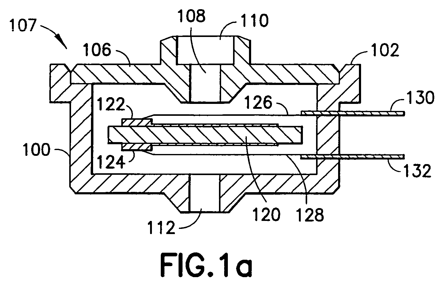
- Figure 1 (a) shows a top unit that is employed in a detection apparatus according to an embodiment of the present invention
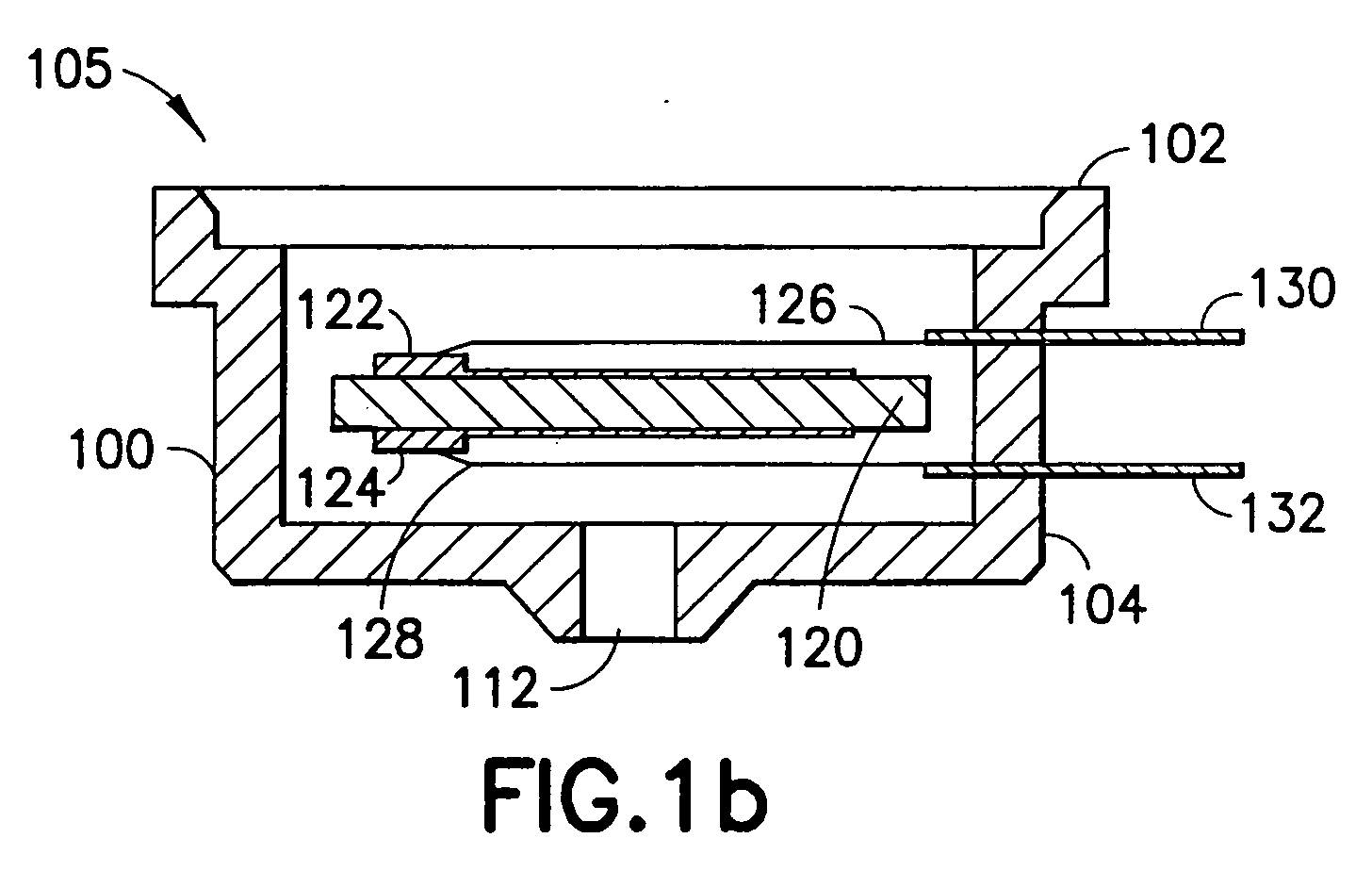
- Figure 1 (b) shows a base unit that is employed in a detection apparatus according to an embodiment of the present invention
- Figure 1(c) shows a bottom unit that is employed in a detection apparatus according to the present invention
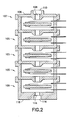
- Figure 2 illustrates a stack of base units, with a top unit at the top, and a bottom unit at the bottom according to an embodiment of the present invention
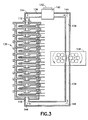
- Figure 3 shows a stack of base units and a pump, whereby the liquid sample is entered into the detection device through a fill and vent unit, and is re-circulated through the stack of base units by means of a peristaltic pump and a loop of flexible tubing;
- Figure 4 illustrates the sample flow within a base unit that provides maximum contact of target molecules with the sensing surface according to an embodiment of the present invention
- Figure 5 illustrates schematically a complete apparatus according to an embodiment of the present invention, whereby the sensing surfaces within the base units are electro-acoustically interrogated according to an embodiment of the present invention
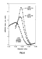
- Figure 6 shows experimental results illustrating the resonance spectrum of a 14.3-MHz piezo-electric quartz crystal under increasing liquid loading conditions
- Figure 7(a) illustrates experimental data in the form of acoustic spectra with plastic PMMA beads attached to the piezo-electric quartz crystal
- Figure 7(b) illustrates experimental data in the form of acoustic spectra with no beads attached.
- An apparatus comprises in its simplest form a base unit as shown in Fig. 1(b).
- the base unit contains a housing 100 that has features allowing the stacking of such base units.
- One of said features has the form of flange 102, whereby the inner opening of flange 102 has a diameter that is identical to the outer diameter of housing 100 on its opposite end 104.
- a second base unit can be attached to the first base unit with the opposite end 104 of the second base unit.
- a stack of base units 105 as shown in Fig. 2 can be built.
- a stack of base units as shown in Fig. 2 preferably contains identical base units, except for the top unit 107 and the bottom unit 109.
- Fig. 1(a) shows a top unit 107 in more detail
- Fig. 1(c) shows a bottom unit 109 in more detail.
- a top unit 107 has a lid 106 attached to flange 102.
- Lid 106 contains an opening 108 for receiving sample fluid, and a second flange 110 allowing attaching a fluid conduit such as flexible tubing.
- a base unit 105 comprises a simple through hole 112 in its lower end 104
- a bottom unit 109 contains a through hole 114 and a third flange 116 in its lower end 118, also allowing attaching a fluid conduit such as flexible tubing.
- base units 105, top units 107, and bottom units 109 each contain a body 120 with a sensing surface, whereby the sensing surface has preferably been prepared to allow for specific binding of target molecules.
- body 120 represents a piezo-acoustic crystal that can be brought into mechanical vibration by means of an electrical RF excitation.
- crystal 120 contains electrodes 122 and 124, and crystal 120 is mounted within a unit by means of two support wires 126 and 128 that serve also as electrical conductors for bringing the RF field to the crystal, and picking up an electrical detection signal from the crystal.
- Support wires 126 and 128 are preferably connected to feed-throughs 130 and 132 that extend through a unit's housing 100 to the outside of the unit.
- body 120 is presently contemplated to embody the best mode of the invention as an electro-acoustic body such as a piezo-electric device.
- sensing bodies are considered to be within the scope of the present invention, including bodies with surfaces prepared for binding to specific target molecules, as well as bodies with surface not intended for binding.
- sensing bodies that generate a sensor output signal based on changes in the bodies' electrical conductivity, and electro-chemical sensing bodies are specifically considered to be within the scope of the present invention.
- Other types of sensing bodies should be considered within the scope of the invention as well.
- the liquid sample is guided into the unit(s) via tubing 134, which is illustrated in Fig. 3.
- a closed loop of such tubing 134 is provided to allow for continuous re-circulation of sample fluid through the unit(s) 136.
- the fluid circulation is preferably achieved by utilizing flexible tubing, and by mounting a peristaltic pump 138 onto the closed tubing loop.
- a fill-and-vent unit 140 with a removable lid 142 allows bringing the liquid sample into the system.
- the liquid sample enters the stack of base units at flange 110. After passing through all units, the liquid sample leaves the stack of units at flange 115, passes peristaltic pump 138, and re-enters the stack of units again at flange 110.
- the liquid sample containing the target molecules in low concentration is guided across the sensing surface or surfaces of crystal(s) 120, which is indicated by arrows 146 and 148. This more readily brings the few target molecules in close proximity to the sensing surface, resulting in more efficient specific binding during the continuous re-circulation of the liquid sample. Therefore, no pre-concentration step such as centrifugation is required.
- Fig. 5 illustrates schematically a complete apparatus according to the present invention, whereby the sensing surfaces within the stack of base units 136 are interrogated by applying principles of electro-acoustics.
- the liquid sample containing the target molecules of interest in low concentration is introduced into the apparatus at fill-and-vent unit 140, which has a removable lid 142.
- a closed loop of tubing 134 connects fill-and-vent unit 140 with the stack of units 136, and with a peristaltic pump 138.
- tubing 134 is made out of flexible material.
- a computer 150 is connected with an electronic signal source 152, which is in turn connected with a connector and directional coupler 154 at the feed-throughs described and/or shown in Figs. 1 to 4.
- Connector and directional coupler 154 guides an RF signal from signal source 152 towards piezo-acoustic crystals 120 within the stack of units 136.
- Connector and directional coupler 154 is also connected with the input of an RF receiver 156, and the output of RF receiver 156 is connected to computer 150. Finally, computer 150 is connected to a pump driver 158 that in turn is connected to peristaltic pump 138. Arrows 144 in Fig. 5 show how the liquid sample circulates within tubing 134.
- computer 150 triggers pump driver 158 and, consequently, peristaltic pump 138. Due to this action, the liquid sample starts circulating within the system and, as shown in Fig. 4, passes the sensing surfaces of piezo-electric crystals 120 within stack 136 in close proximity, which enhances the probability for specific binding on said surfaces.
- computer 150 and pump driver 158 are programmed to periodically reverse the flow or liquid to further enhance binding efficiency and to reduce dead-zones in the liquid, such as might develop in comers of housing 100.
- a predetermined incubation time period e.g. 30 minutes
- computer 150 activates signal source 152, which results in an oscillation of said sensing surfaces on crystals 120.
- target molecules will break away from said sensing surfaces due to the surfaces' oscillation, which results in an acousto-electric signal that is being detected by RF receiver 156.
- Fig. 6 shows experimental results illustrating the resonance spectrum of a 14.3-MHz piezo-acoustic quartz crystal under increasing liquid loading conditions.
- Fig. 6 illustrates the fact that if only a small percentage of the sensing surface comes into contact with the liquid sample (0.3 microliter water load), then the resonance curve is very narrow. If the crystal is completely immersed in liquid, as is the case in an apparatus according to the present invention, then the resonance curve becomes wider, but it is still narrow enough to allow for acousto-electric detection of binding events.
- Fig. 7(a) illustrates experimental data in the form of acoustic spectra with plastic PMMA beads attached to the above-mentioned piezo-acoustic quartz crystal.
- Figure 7(b) illustrates experimental data in the form of acoustic spectra with no beads attached. As illustrated in Fig. 7(a), if targets such as small beads had been bound to the sensing surface, peaks 160 with amplitudes larger than noise peaks are observed.
- Fig. 7(b) illustrates lower amplitude noise peaks 162.
- the stack of base units 136 may comprise base units having identical sensing surfaces, or may comprise base units having sensing surfaces that have been activated for the binding of different target molecules on different crystals. Including sensing surfaces activated for binding to different target molecules achieves multiplexed analyte detection. Including identical sensing surfaces in the stack 136 results in an increased overall size of sensing surface, and, consequently, in an improved detection limit for low analyte concentration.
- the base units for an apparatus according to an embodiment of the present invention are easily manufactured, and advantageously can be produced in large numbers at low cost.
- the sensing surfaces are easily prepared for single base units, before more than one base unit are connected together. Due to the open flange design, before connecting them, the interior of a base unit is readily accessible, which also makes the mounting of crystals 120 very easy.
- members from multiple groups can be connected together to form stacks of base units 136 that represent specific multi-analyte assays.
- the re-circulation of the sample liquid can be performed over an extended incubation time period to allow for binding of all target molecules that are present within the sample volume. It is possible and advantageous to reverse the flow direction for the liquid sample periodically to avoid trapping of target molecules in comers or other dead zones of the base units.
- the fill-and-vent unit 140 shown in Figs. 3 and 5 can become part of lid 106 in a top unit 107 shown in Figs. 1 to 4.
- a typical electro-acoustic crystal 120 has the shape of a disc with a thickness of approximately 0.1 mm, and a diameter between 5 and 10 mm. Based on this, the volume of a base unit can be as low as 100 microliters. This would result in an overall sample volume around 1 ml for a stacked detection device 136 containing ten base units.
- the closed loop tubing 134 is preferably made out of a flexible plastic material, but of course it will be readily understood by those of skill in the art that a stiff tubing material or any other suitable material could be used without departing from the spirit of the invention. Those of skill in the art will also recognize that peristaltic pump 138 can be replaced with any other kind of suitable pumping device.
- an apparatus according to the present invention is not limited to the use of piezo-acoustic crystals. It would still be within the scope of the invention to use piezo-acoustic plastic materials, piezo-acoustic foils, piezo-acoustic microstructures on solid substrates, or the like.
Landscapes
- Physics & Mathematics (AREA)
- Acoustics & Sound (AREA)
- Health & Medical Sciences (AREA)
- Life Sciences & Earth Sciences (AREA)
- Chemical & Material Sciences (AREA)
- Analytical Chemistry (AREA)
- Biochemistry (AREA)
- General Health & Medical Sciences (AREA)
- General Physics & Mathematics (AREA)
- Immunology (AREA)
- Pathology (AREA)
- Investigating Or Analyzing Materials By The Use Of Ultrasonic Waves (AREA)
- Automatic Analysis And Handling Materials Therefor (AREA)
Abstract
Description
Claims (8)
- A liquid sample sensing device comprising a top unit, at least one base unit, and a bottom unit arranged in a stack, each base unit comprising:a volume defined by at least one side wall, a top flange member, and a bottom member having disposed therein at least one sensing body comprising a respective surface that is activated for binding to target molecules, said sensing body having attached thereto at least two electrodes, said electrodes extending outside said volume,said top flange member adapted to engage a bottom member of an adjacent base unit such that said stack is substantially sealed,said device further comprising a pump having a loop of tubing connected to a top of said top unit and a bottom of said bottom unit to form a closed loop.
- The liquid sample sensing device of claim 1, wherein said pump is a peristaltic pump, wherein a plurality of said sensing body surfaces are activated for binding to the same type of target molecule or to a different type of target molecule, wherein each base unit top flange member is adapted to engage a bottom member of an adjacent base unit or top unit, and wherein each base unit bottom member is adapted to engage a top flange member of an adjacent base unit or bottom unit.
- The liquid sample sensing device of claim 1, wherein said bottom member comprises a liquid exit opening adapted to allow liquid to flow out of said volume and into one of a next base unit and said bottom unit.
- The liquid sample sensing device of claim 3, wherein said exit opening is narrow relative to a surface area of said sensing body, and wherein said exit opening is located substantially adjacent to said surface to cause a liquid sample flowing through said volume to flow over a substantial portion of said surface.
- A method of sensing target molecules within a liquid sample comprising:providing a top unit, at least one base unit, and a bottom unit, each base unit comprising a volume defined by at least one side wall, a top flange member, and a bottom member having disposed therein at least one sensing body, each of said sensing bodies having attached thereto at least two electrodes, said electrodes extending outside said volume, said bottom member comprising an opening substantially adjacent to said sensing body to allow fluid to flow from said volume into said adjacent unit or said bottom unit, said top flange member adapted to engage a bottom member of a top flange unit of an adjacent base unit or a bottom unit to form a substantially sealed volume in said adjacent unit or bottom unit,stacking said top unit, at least one base unit, and bottom unit to form a stack;attaching a pump and a closed loop of tubing to said top unit and said bottom unit;pumping sample fluid through said stack for a predetermined incubation time period;exciting at least one of said sensing bodies through said respective electrodes; andmeasuring electrical signals generated by said sensing body at said electrodes.
- The method of claim 5, wherein said tubing is flexible tubing, and said pump is a peristaltic pump, wherein each said sensing body comprises a surface that is activated for binding to target molecules, and wherein a plurality of said sensing body surfaces are activated for binding to the same type of target molecule or a different type of target molecule.
- A liquid sample sensing device comprising:a stack of at least one stackable base units, whereby each of said at least one base units comprises(a) a sidewall and a bottom member defining an interior space, with the bottom member adapted to connect to the sidewall of an adjacent base unit in said stack;(b) at least one body mounted inside said interior space, each said body containing at least one sensing surface; and(c) a through hole in said bottom member allowing for fluid communication with the adjacent base unit in said stack, and adapted to direct liquid sample flow onto the at least one sensing surface of said body in the adjacent base unit;a lid attached to said sidewalls of a top base unit, said lid having an entrance hole adapted for receiving the exit conduit of a sample re-circulation loop; andwherein said through hole of a bottom base unit comprises an exit hole adapted for receiving the entrance conduit of said sample re-circulation loop.
- The liquid sample sensing device of claim 7, further comprising a pump in said sample re-circulation loop, adapted to pump sample liquid through said stack, or optionally, further comprising electrodes connected to said body and extending outside of said interior space, or optionally, wherein said sidewall of said base units further comprises a flange adapted to tightly connect to a bottom member of an adjacent base unit or optionally, wherein said sidewall further comprises a flange adapted to form a substantially air-tight seal with the bottom member of an adjacent base unit.
Applications Claiming Priority (2)
| Application Number | Priority Date | Filing Date | Title |
|---|---|---|---|
| US461263 | 1990-01-05 | ||
| US10/461,263 US6826949B1 (en) | 2003-06-13 | 2003-06-13 | Method and apparatus for guiding a liquid sample towards a sensing surface |
Publications (2)
| Publication Number | Publication Date |
|---|---|
| EP1486788A2 true EP1486788A2 (en) | 2004-12-15 |
| EP1486788A3 EP1486788A3 (en) | 2005-08-31 |
Family
ID=33299787
Family Applications (1)
| Application Number | Title | Priority Date | Filing Date |
|---|---|---|---|
| EP04013867A Withdrawn EP1486788A3 (en) | 2003-06-13 | 2004-06-14 | Method and apparatus for guiding a liquid sample towards a sensing surface |
Country Status (2)
| Country | Link |
|---|---|
| US (1) | US6826949B1 (en) |
| EP (1) | EP1486788A3 (en) |
Families Citing this family (9)
| Publication number | Priority date | Publication date | Assignee | Title |
|---|---|---|---|---|
| US6990852B2 (en) * | 2003-07-28 | 2006-01-31 | Becton Dickinson & Company | System and method for detecting particles |
| US7082811B2 (en) * | 2003-08-06 | 2006-08-01 | Msp Corporation | Cascade impactor with individually driven impactor plates |
| US6978656B2 (en) * | 2003-10-31 | 2005-12-27 | Hewlett-Packard Development Company, L.P. | Transducer-based sensor system and method |
| US7824927B2 (en) * | 2005-04-05 | 2010-11-02 | George Mason Intellectual Properties, Inc. | Analyte detection using an active assay |
| CA2946024C (en) * | 2007-05-03 | 2020-06-02 | Clondiag Gmbh | Devices and methods for detecting analytes |
| CA2824325C (en) * | 2010-01-12 | 2018-06-26 | Fiducie Aeternum | Fluid sampling system |
| US10107784B2 (en) | 2014-12-29 | 2018-10-23 | Concentric Meter Corporation | Electromagnetic transducer |
| US10126266B2 (en) | 2014-12-29 | 2018-11-13 | Concentric Meter Corporation | Fluid parameter sensor and meter |
| WO2016109447A1 (en) | 2014-12-29 | 2016-07-07 | Concentric Meter Corporation | Fluid parameter sensor and meter |
Family Cites Families (14)
| Publication number | Priority date | Publication date | Assignee | Title |
|---|---|---|---|---|
| US3238452A (en) * | 1961-10-18 | 1966-03-01 | Union Oil Co | Apparatus and method for detecting contaminants in a fluid |
| US3583627A (en) * | 1969-09-04 | 1971-06-08 | Onslow H Wilson | Apparatus for the concentration of macromolecules and subcellular particles from dilute solutions |
| US3983743A (en) * | 1973-09-19 | 1976-10-05 | Sierra Instruments, Inc. | Apparatus and method for the analysis of a particle-laden gas |
| US4242096A (en) * | 1977-11-14 | 1980-12-30 | Minnesota Mining And Manufacturing Company | Immunoassay for antigens |
| US4387603A (en) * | 1979-06-25 | 1983-06-14 | Nelson Philip A | Bounceless high pressure drop cascade impactor and a method for determining particle size distribution of an aerosol |
| BR8506430A (en) * | 1984-04-03 | 1986-04-15 | Health Lab Service Board | PROCESS TO DETERMINE THE AMOUNT OF BIOLOGICAL MATERIA CONTAINED IN A FLUID MEDIA, PROCESS AND APPARATUS TO MEASURE THE CONCENTRATION OF BIOLOGICAL PARTICLES IN A FLOWING MEDIA AND PROBE FOR USE IN MEASURING THE QUANTITY OF BIOLOGICAL MATERIA IN A FLUID MEDIUM |
| EP0215669A3 (en) * | 1985-09-17 | 1989-08-30 | Seiko Instruments Inc. | Analytical device and method for analysis of biochemicals, microbes and cells |
| US5076933A (en) * | 1990-06-29 | 1991-12-31 | Coulter Corporation | Process and apparatus for removal of dna and viruses |
| EP0484278B1 (en) * | 1990-11-01 | 1995-04-12 | Ciba-Geigy Ag | Device for preparing liquid samples for chemical analysis |
| US5455475A (en) * | 1993-11-01 | 1995-10-03 | Marquette University | Piezoelectric resonant sensor using the acoustoelectric effect |
| US5641895A (en) * | 1995-05-01 | 1997-06-24 | Fsi International, Inc. | Dynamic contaminant extraction measurement for chemical distribution systems |
| JPH09113434A (en) * | 1995-10-20 | 1997-05-02 | Ngk Insulators Ltd | Axial particle sensor |
| US6101886A (en) * | 1997-11-26 | 2000-08-15 | Pacific Sierra Research | Multi-stage sampler concentrator |
| US7186379B2 (en) * | 2001-02-07 | 2007-03-06 | Battelle Energy Alliance, Llc | Continuous real-time measurement of aqueous cyanide |
-
2003
- 2003-06-13 US US10/461,263 patent/US6826949B1/en not_active Expired - Fee Related
-
2004
- 2004-06-14 EP EP04013867A patent/EP1486788A3/en not_active Withdrawn
Also Published As
| Publication number | Publication date |
|---|---|
| US6826949B1 (en) | 2004-12-07 |
| US20040261508A1 (en) | 2004-12-30 |
| EP1486788A3 (en) | 2005-08-31 |
Similar Documents
| Publication | Publication Date | Title |
|---|---|---|
| Länge et al. | Surface acoustic wave biosensors: a review | |
| JP5197357B2 (en) | Method and apparatus for detecting an analyte using an acoustic device | |
| US8733154B2 (en) | Liquid analysis using capacitative micromachined ultrasound transducers | |
| US20090227042A1 (en) | Coustic Concentration Method and Device and a Reaction Method | |
| US20050106064A1 (en) | Microfluidic cell and method for sample handling | |
| US8276433B2 (en) | Sensor for measuring properties of liquids and gases | |
| US10466194B2 (en) | Piezoelectric biochips having fluidic channels | |
| US7330795B2 (en) | Method and apparatus for providing signal analysis of a BioNEMS resonator or transducer | |
| US20100163410A1 (en) | Electronic detection of biological materials | |
| US9151752B2 (en) | Method for amplifying variation of frequency of signal in piezoelectrical biosensor | |
| US6826949B1 (en) | Method and apparatus for guiding a liquid sample towards a sensing surface | |
| EP1756562A1 (en) | Surface acoustic wave sensor comprising a hydrogel | |
| CN102830161A (en) | Biosensor utilizing a resonator having a functionalized surface | |
| Durmuş et al. | Acoustic-based biosensors | |
| Kato et al. | Resonance acoustic microbalance with naked-embedded quartz (RAMNE-Q) biosensor fabricated by microelectromechanical-system process | |
| US7335336B1 (en) | Sensor array using lateral field excited resonators | |
| EP3377886A1 (en) | Acoustic resonator with reduced mechanical clamping of an active region for enhanced shear mode response | |
| JP2009517661A (en) | Methods and apparatus for assay measurements | |
| JP2010286465A (en) | SAW sensor device | |
| WO2009145385A1 (en) | Resonance characteristic measurement apparatus of cantilever structure and measurement method thereof | |
| US7543476B2 (en) | Rupture event sensors | |
| CN101213452B (en) | Method and apparatus for detecting analytes using an acoustic device | |
| CN107921442A (en) | Electromagnetic Fluid Filters Using Magnetostrictive Sensors | |
| Giouroudi et al. | BioMEMS in diagnostics: A review and recent developments | |
| US20060223195A1 (en) | Stress based removal of nonspecific binding from surfaces |
Legal Events
| Date | Code | Title | Description |
|---|---|---|---|
| PUAI | Public reference made under article 153(3) epc to a published international application that has entered the european phase |
Free format text: ORIGINAL CODE: 0009012 |
|
| AK | Designated contracting states |
Kind code of ref document: A2 Designated state(s): AT BE BG CH CY CZ DE DK EE ES FI FR GB GR HU IE IT LI LU MC NL PL PT RO SE SI SK TR |
|
| AX | Request for extension of the european patent |
Extension state: AL HR LT LV MK |
|
| PUAL | Search report despatched |
Free format text: ORIGINAL CODE: 0009013 |
|
| AK | Designated contracting states |
Kind code of ref document: A3 Designated state(s): AT BE BG CH CY CZ DE DK EE ES FI FR GB GR HU IE IT LI LU MC NL PL PT RO SE SI SK TR |
|
| AX | Request for extension of the european patent |
Extension state: AL HR LT LV MK |
|
| RIC1 | Information provided on ipc code assigned before grant |
Ipc: 7G 01N 33/00 B Ipc: 7G 01N 29/00 B Ipc: 7G 01N 27/00 A |
|
| 17P | Request for examination filed |
Effective date: 20060202 |
|
| AKX | Designation fees paid |
Designated state(s): DE FR GB IT |
|
| 17Q | First examination report despatched |
Effective date: 20060711 |
|
| STAA | Information on the status of an ep patent application or granted ep patent |
Free format text: STATUS: THE APPLICATION IS DEEMED TO BE WITHDRAWN |
|
| 18D | Application deemed to be withdrawn |
Effective date: 20070123 |