EP1486714A1 - Fluid coupling - Google Patents
Fluid coupling Download PDFInfo
- Publication number
- EP1486714A1 EP1486714A1 EP02705285A EP02705285A EP1486714A1 EP 1486714 A1 EP1486714 A1 EP 1486714A1 EP 02705285 A EP02705285 A EP 02705285A EP 02705285 A EP02705285 A EP 02705285A EP 1486714 A1 EP1486714 A1 EP 1486714A1
- Authority
- EP
- European Patent Office
- Prior art keywords
- coupling
- guide
- annular
- coupling members
- sealing portion
- Prior art date
- Legal status (The legal status is an assumption and is not a legal conclusion. Google has not performed a legal analysis and makes no representation as to the accuracy of the status listed.)
- Granted
Links
Images

Classifications
-
- F—MECHANICAL ENGINEERING; LIGHTING; HEATING; WEAPONS; BLASTING
- F16—ENGINEERING ELEMENTS AND UNITS; GENERAL MEASURES FOR PRODUCING AND MAINTAINING EFFECTIVE FUNCTIONING OF MACHINES OR INSTALLATIONS; THERMAL INSULATION IN GENERAL
- F16J—PISTONS; CYLINDERS; SEALINGS
- F16J15/00—Sealings
- F16J15/02—Sealings between relatively-stationary surfaces
-
- F—MECHANICAL ENGINEERING; LIGHTING; HEATING; WEAPONS; BLASTING
- F16—ENGINEERING ELEMENTS AND UNITS; GENERAL MEASURES FOR PRODUCING AND MAINTAINING EFFECTIVE FUNCTIONING OF MACHINES OR INSTALLATIONS; THERMAL INSULATION IN GENERAL
- F16J—PISTONS; CYLINDERS; SEALINGS
- F16J15/00—Sealings
- F16J15/02—Sealings between relatively-stationary surfaces
- F16J15/06—Sealings between relatively-stationary surfaces with solid packing compressed between sealing surfaces
- F16J15/062—Sealings between relatively-stationary surfaces with solid packing compressed between sealing surfaces characterised by the geometry of the seat
-
- F—MECHANICAL ENGINEERING; LIGHTING; HEATING; WEAPONS; BLASTING
- F16—ENGINEERING ELEMENTS AND UNITS; GENERAL MEASURES FOR PRODUCING AND MAINTAINING EFFECTIVE FUNCTIONING OF MACHINES OR INSTALLATIONS; THERMAL INSULATION IN GENERAL
- F16J—PISTONS; CYLINDERS; SEALINGS
- F16J15/00—Sealings
- F16J15/02—Sealings between relatively-stationary surfaces
- F16J15/06—Sealings between relatively-stationary surfaces with solid packing compressed between sealing surfaces
- F16J15/10—Sealings between relatively-stationary surfaces with solid packing compressed between sealing surfaces with non-metallic packing
- F16J15/104—Sealings between relatively-stationary surfaces with solid packing compressed between sealing surfaces with non-metallic packing characterised by structure
-
- F—MECHANICAL ENGINEERING; LIGHTING; HEATING; WEAPONS; BLASTING
- F16—ENGINEERING ELEMENTS AND UNITS; GENERAL MEASURES FOR PRODUCING AND MAINTAINING EFFECTIVE FUNCTIONING OF MACHINES OR INSTALLATIONS; THERMAL INSULATION IN GENERAL
- F16L—PIPES; JOINTS OR FITTINGS FOR PIPES; SUPPORTS FOR PIPES, CABLES OR PROTECTIVE TUBING; MEANS FOR THERMAL INSULATION IN GENERAL
- F16L19/00—Joints in which sealing surfaces are pressed together by means of a member, e.g. a swivel nut, screwed on, or into, one of the joint parts
-
- F—MECHANICAL ENGINEERING; LIGHTING; HEATING; WEAPONS; BLASTING
- F16—ENGINEERING ELEMENTS AND UNITS; GENERAL MEASURES FOR PRODUCING AND MAINTAINING EFFECTIVE FUNCTIONING OF MACHINES OR INSTALLATIONS; THERMAL INSULATION IN GENERAL
- F16L—PIPES; JOINTS OR FITTINGS FOR PIPES; SUPPORTS FOR PIPES, CABLES OR PROTECTIVE TUBING; MEANS FOR THERMAL INSULATION IN GENERAL
- F16L19/00—Joints in which sealing surfaces are pressed together by means of a member, e.g. a swivel nut, screwed on, or into, one of the joint parts
- F16L19/02—Pipe ends provided with collars or flanges, integral with the pipe or not, pressed together by a screwed member
- F16L19/0212—Pipe ends provided with collars or flanges, integral with the pipe or not, pressed together by a screwed member using specially adapted sealing means
-
- F—MECHANICAL ENGINEERING; LIGHTING; HEATING; WEAPONS; BLASTING
- F16—ENGINEERING ELEMENTS AND UNITS; GENERAL MEASURES FOR PRODUCING AND MAINTAINING EFFECTIVE FUNCTIONING OF MACHINES OR INSTALLATIONS; THERMAL INSULATION IN GENERAL
- F16L—PIPES; JOINTS OR FITTINGS FOR PIPES; SUPPORTS FOR PIPES, CABLES OR PROTECTIVE TUBING; MEANS FOR THERMAL INSULATION IN GENERAL
- F16L19/00—Joints in which sealing surfaces are pressed together by means of a member, e.g. a swivel nut, screwed on, or into, one of the joint parts
- F16L19/02—Pipe ends provided with collars or flanges, integral with the pipe or not, pressed together by a screwed member
- F16L19/0212—Pipe ends provided with collars or flanges, integral with the pipe or not, pressed together by a screwed member using specially adapted sealing means
- F16L19/0218—Pipe ends provided with collars or flanges, integral with the pipe or not, pressed together by a screwed member using specially adapted sealing means comprising only sealing rings
-
- F—MECHANICAL ENGINEERING; LIGHTING; HEATING; WEAPONS; BLASTING
- F16—ENGINEERING ELEMENTS AND UNITS; GENERAL MEASURES FOR PRODUCING AND MAINTAINING EFFECTIVE FUNCTIONING OF MACHINES OR INSTALLATIONS; THERMAL INSULATION IN GENERAL
- F16L—PIPES; JOINTS OR FITTINGS FOR PIPES; SUPPORTS FOR PIPES, CABLES OR PROTECTIVE TUBING; MEANS FOR THERMAL INSULATION IN GENERAL
- F16L25/00—Construction or details of pipe joints not provided for in, or of interest apart from, groups F16L13/00 - F16L23/00
- F16L25/0018—Abutment joints
-
- F—MECHANICAL ENGINEERING; LIGHTING; HEATING; WEAPONS; BLASTING
- F16—ENGINEERING ELEMENTS AND UNITS; GENERAL MEASURES FOR PRODUCING AND MAINTAINING EFFECTIVE FUNCTIONING OF MACHINES OR INSTALLATIONS; THERMAL INSULATION IN GENERAL
- F16L—PIPES; JOINTS OR FITTINGS FOR PIPES; SUPPORTS FOR PIPES, CABLES OR PROTECTIVE TUBING; MEANS FOR THERMAL INSULATION IN GENERAL
- F16L27/00—Adjustable joints; Joints allowing movement
- F16L27/08—Adjustable joints; Joints allowing movement allowing adjustment or movement only about the axis of one pipe
- F16L27/0804—Adjustable joints; Joints allowing movement allowing adjustment or movement only about the axis of one pipe the fluid passing axially from one joint element to another
- F16L27/0808—Adjustable joints; Joints allowing movement allowing adjustment or movement only about the axis of one pipe the fluid passing axially from one joint element to another the joint elements extending coaxially for some distance from their point of separation
- F16L27/0812—Adjustable joints; Joints allowing movement allowing adjustment or movement only about the axis of one pipe the fluid passing axially from one joint element to another the joint elements extending coaxially for some distance from their point of separation with slide bearings
- F16L27/082—Adjustable joints; Joints allowing movement allowing adjustment or movement only about the axis of one pipe the fluid passing axially from one joint element to another the joint elements extending coaxially for some distance from their point of separation with slide bearings having axial sealing
-
- F—MECHANICAL ENGINEERING; LIGHTING; HEATING; WEAPONS; BLASTING
- F16—ENGINEERING ELEMENTS AND UNITS; GENERAL MEASURES FOR PRODUCING AND MAINTAINING EFFECTIVE FUNCTIONING OF MACHINES OR INSTALLATIONS; THERMAL INSULATION IN GENERAL
- F16L—PIPES; JOINTS OR FITTINGS FOR PIPES; SUPPORTS FOR PIPES, CABLES OR PROTECTIVE TUBING; MEANS FOR THERMAL INSULATION IN GENERAL
- F16L27/00—Adjustable joints; Joints allowing movement
- F16L27/08—Adjustable joints; Joints allowing movement allowing adjustment or movement only about the axis of one pipe
- F16L27/0804—Adjustable joints; Joints allowing movement allowing adjustment or movement only about the axis of one pipe the fluid passing axially from one joint element to another
- F16L27/0808—Adjustable joints; Joints allowing movement allowing adjustment or movement only about the axis of one pipe the fluid passing axially from one joint element to another the joint elements extending coaxially for some distance from their point of separation
- F16L27/0824—Adjustable joints; Joints allowing movement allowing adjustment or movement only about the axis of one pipe the fluid passing axially from one joint element to another the joint elements extending coaxially for some distance from their point of separation with ball or roller bearings
- F16L27/0828—Adjustable joints; Joints allowing movement allowing adjustment or movement only about the axis of one pipe the fluid passing axially from one joint element to another the joint elements extending coaxially for some distance from their point of separation with ball or roller bearings having radial bearings
-
- Y—GENERAL TAGGING OF NEW TECHNOLOGICAL DEVELOPMENTS; GENERAL TAGGING OF CROSS-SECTIONAL TECHNOLOGIES SPANNING OVER SEVERAL SECTIONS OF THE IPC; TECHNICAL SUBJECTS COVERED BY FORMER USPC CROSS-REFERENCE ART COLLECTIONS [XRACs] AND DIGESTS
- Y10—TECHNICAL SUBJECTS COVERED BY FORMER USPC
- Y10S—TECHNICAL SUBJECTS COVERED BY FORMER USPC CROSS-REFERENCE ART COLLECTIONS [XRACs] AND DIGESTS
- Y10S277/00—Seal for a joint or juncture
- Y10S277/925—Snap fit feature for mounting or assembly of seal
-
- Y—GENERAL TAGGING OF NEW TECHNOLOGICAL DEVELOPMENTS; GENERAL TAGGING OF CROSS-SECTIONAL TECHNOLOGIES SPANNING OVER SEVERAL SECTIONS OF THE IPC; TECHNICAL SUBJECTS COVERED BY FORMER USPC CROSS-REFERENCE ART COLLECTIONS [XRACs] AND DIGESTS
- Y10—TECHNICAL SUBJECTS COVERED BY FORMER USPC
- Y10S—TECHNICAL SUBJECTS COVERED BY FORMER USPC CROSS-REFERENCE ART COLLECTIONS [XRACs] AND DIGESTS
- Y10S285/00—Pipe joints or couplings
- Y10S285/917—Metallic seals
Definitions
- the present invention relates to fluid couplings, and more particularly to fluid couplings comprising a gasket which gives predetermined sealing properties to the coupling when deformed.
- FIG. 4 shows a fluid coupling already known.
- first and second coupling members 41, 42 provided with annular projections 41a, 42a on opposed faces thereof are butted against each other with a gasket 43 interposed therebetween.
- a cap nut 44 screwed on the first coupling member 41 is tightened up to deform the gasket 43 and give a proper sealing force.
- Indicated at 45 is a thrust ring for facilitating the rotation of the cap nut 44.
- the proper amount of rotation to be given to the cap nut 44 after the nut is manually tightened is predetermined so as to obtain the proper sealing force by pretightening the nut manually and fully tightening up the nut with a jig.
- An object of the present invention is to provide a fluid coupling which is made free of faulty tightening such as excessive tightening.
- the present invention provides a fluid coupling comprising a first and a second coupling member having respective fluid channels in communication with each other, an annular gasket interposed between butting end faces of the two coupling members, and screw means for connecting the two coupling members together, each of the coupling members being provided in the butting end face thereof with an annular recessed portion surrounding the fluid channel thereof and having an annular projection formed in a bottom face of the recessed portion, the gasket comprising a sealing portion having an outside diameter smaller than the diameter of the recessed portion and positioned between the annular projections of the two coupling members, and a guide having an outside diameter permitting the guide to be fitted into the recessed portion and positioned externally of the sealing portion, the butting end faces of the two coupling members being movable into contact with each other when the coupling is tightened up properly.
- the sealing portion of the gasket is deformed by tightening the coupling to produce a sealing force, and further continued tightening of the coupling moves the butting end faces of the two coupling members into contact with each other. This makes it impossible to tighten up the coupling any longer, consequently precluding the coupling from being tightened excessively or insufficiently.
- the guide restrains the coupling member from shifting radially thereof beyond a predetermined range.
- the sealing portion of the gasket and the guide thereof may be in the form of an integral piece but are preferably connected together separably, for example, by a snap ring.
- the sealing portion preferably has an annular groove formed in an outer periphery thereof to connect the sealing portion and the guide together by a snap ring fitted in the annular groove.
- the guide comprise a large-diameter portion fitting in the recessed portion of one of the coupling members without play and a small-diameter portion loosely fitted in the recessed portion of the other coupling member.
- the guide is separably connected to one of the coupling members by a snap ring so as not to slip out of the coupling member.
- the guide preferably has an annular furrow formed in an outer periphery of the large-diameter portion thereof to connect the guide and one of the coupling members together by a snap ring fitted in the annular furrow. This prevents the gasket from inadvertently slipping out of the coupling member when the coupling is disassembled.
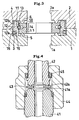
- FIG. 1 is a view showing a gasket for use in a fluid coupling according to the invention.
- FIG. 2 is a view in longitudinal section showing the fluid coupling of the invention as tightened manually.
- FIG. 3 is a view in longitudinal section showing the fluid coupling of the invention as completely tightened up.
- FIG. 4 is a view in longitudinal section showing a conventional fluid coupling.
- the fluid coupling of the invention has a structure for joining two coupling members 1, 2 fluid-tightly.
- the coupling comprises first and second coupling members 1, 2 having respective fluid channels 1a, 2a communicating with each other, an annular gasket 10 interposed between butting end faces of the two coupling members 1, 2, and screw means for fastening the coupling members 1, 2 together.
- screw means is not shown, various known means are usable such as the one shown in FIG. 4.
- Annular recessed portions 3, 4 surrounding the openings of the fluid channels 1a, 2a are formed in the butting end faces of the first and second coupling members 1, 2, respectively, and annular projections 5, 6 are formed in the bottom faces of the recessed portions 3, 4.
- the gasket 10 comprises an annular sealing portion 11 positioned between the annular projections 5, 6 of the coupling members 3, 4, and an annular guide 12 attached to the outer periphery of the sealing portion 11 by a snap ring 13.
- the sealing portion 11 is made of stainless steel and is a portion serving the same function as conventional gaskets and having an outside diameter smaller than the diameter of the annular recessed portions 3, 4 of the coupling members 1, 2 and an inside diameter approximately equal to the diameter of the fluid channels 1a, 2a of the coupling members 1, 2.
- the annular projections 5, 6 of the coupling members 1, 2 are so provided as to come into contact with the midportion of the sealing portion 11.
- the sealing portion 11 is provided in its outer periphery with an annular groove 14 for the snap ring 13 to fit in.
- the snap ring 13 is C-shaped so as to exhibit elasticity, has an outside diameter greater than the inside diameter of the guide 12 when in a free state and prevents the guide 12 from slipping off from the sealing portion 11 by virtue of the elastic force of the ring 13 acting to expand radially outward.
- the diameter of the bottom face of the sealing portion 11 which face defines the annular groove 14 is smaller than the inside diameter of the snap ring 13 in its free state, and the snap ring 13 is not restrained from moving radially inwardly thereof. Accordingly, the guide 12 and the sealing portion 11 are held connected together unless subjected to a force from outside and can be readily separated from each other when subjected to a force greater than the elastic force of the snap ring 13.
- the guide 12 is made of stainless steel and has such an outside diameter that the guide 12 can be fitted into the annular recessed portions 3, 4 of the coupling members 1, 2, and such an inside diameter as to fit around the sealing portion 11.
- the guide 12 comprises a large-diameter portion 12a fittable into the annular recessed portion 3 of the first coupling member 1 without play and a small-diameter portion 12b loosely fittable into the annular recessed portion 4 of the second coupling member 2.
- the large-diameter portion 12a is provided in its outer periphery with an annular furrow 16 for a snap ring 15 to fit in.
- the snap ring 15 is C-shaped so as to be elastic, has an outside diameter larger than the diameter of the annular recessed portion 3 of the first coupling member 1, accordingly, larger than the outside diameter of the large-diameter portion 12a of the guide 12 when in a free state, and is projected outward beyond the outer periphery of the large-diameter portion 12a as shown in FIG. 1.
- the elastic force of the snap ring 15 acting to expand radially outwardly thereof holds the guide 12 on the first coupling member 1.
- the diameter of the bottom face of the large-diameter portion 12a which face defines the annular furrow 16 is smaller than the inside diameter of the snap ring 15 in its free state, and the snap ring 15 is not restrained from moving radially inwardly thereof.
- the gasket 10 is prevented from slipping out of the coupling member 1 while the gasket is not subjected to a force from outside. If subjected to a force greater than the elastic force of the snap ring 15, the gasket 10 is removable from the first coupling member 1 with a small force.
- the guide 12 is provided in its inner periphery with a V-shaped shallow groove 17 for fitting therein an outer peripheral portion of the snap ring 13 to hold the sealing portion 11 and the guide 12 together. This makes it more difficult for the guide 12 to slip off from the sealing portion 11, also serving to position the guide 12 in place relative to the sealing portion 11 radially of the sealing portion 11.
- FIG. 2 shows the fluid coupling of the invention as tightened manually.
- the value obtained by adding the combined height of the annular projections 3, 4 of the two coupling member 1, 2 to the entire thickness of the sealing portion 11 of the gasket 10 is slightly greater than the combined depth of the recessed portions 3, 4 of the two coupling members 1, 2.
- a gap G is therefore formed between the butting end faces (the portions having no recesses 3, 4) of the two coupling members 1, 2.
- FIG. 3 shows the fluid coupling of the invention as tightened up properly.
- the gap G existing in the manually tightened state of FIG. 2 is reduced to zero.
- the gap G between the butting end faces of the two coupling members 1, 2 as tightened manually is made equal to the proper amount of tightening, and when the coupling is tightened up properly, the butting end faces of the two coupling members 1, 2 come into contact with each other.
- the sealing portion 11 of the gasket 10 is deformed first to produce a sealing force, and when the coupling is tightened up continuously, the butting end faces of the two coupling members 1, 2 come into contact with each other, permitting the coupling to be tightened no longer and thus precluding excessive tightening or insufficient tightening.
- the invention provides a fluid coupling which is suitable for use in fluid control devices, for example, of semiconductor fabrication apparatus as a coupling for connecting fluid control units together fluid-tightly.
Landscapes
- Engineering & Computer Science (AREA)
- General Engineering & Computer Science (AREA)
- Mechanical Engineering (AREA)
- Physics & Mathematics (AREA)
- Geometry (AREA)
- Joints With Pressure Members (AREA)
- Gasket Seals (AREA)
- Quick-Acting Or Multi-Walled Pipe Joints (AREA)
Abstract
Description
Claims (4)
- A fluid coupling comprising a first and a second coupling member having respective fluid channels in communication with each other, an annular gasket interposed between butting end faces of the two coupling members, and screw means for connecting the two coupling members together,
each of the coupling members being provided in the butting end face thereof with an annular recessed portion surrounding the fluid channel thereof and having an annular projection formed in a bottom face of the recessed portion, the gasket comprising a sealing portion having an outside diameter smaller than the diameter of the recessed portion and positioned between the annular projections of the two coupling members, and a guide having an outside diameter permitting the guide to be fitted into the recessed portion and positioned externally of the sealing portion, the butting end faces of the two coupling members being movable into contact with each other when the coupling is tightened up properly. - A fluid coupling according to claim 1 wherein the sealing portion has an annular groove formed in an outer periphery thereof, and the sealing portion and the guide are connected together by a snap ring fitted in the annular groove.
- A fluid coupling according to claim 1 wherein the guide comprises a large-diameter portion fitting in the recessed portion of one of the coupling members without play and a small-diameter portion loosely fitted in the recessed portion of the other coupling member.
- A fluid coupling according to claim 3 wherein the guide has an annular furrow formed in an outer periphery of the large-diameter portion thereof, and the guide and one of the coupling members are connected together by a snap ring fitted in the annular furrow.
Applications Claiming Priority (2)
| Application Number | Priority Date | Filing Date | Title |
|---|---|---|---|
| JP2000306419A JP4517325B2 (en) | 2000-10-05 | 2000-10-05 | Fluid coupling |
| PCT/JP2002/002533 WO2003078883A1 (en) | 2000-10-05 | 2002-03-18 | Fluid coupling |
Publications (3)
| Publication Number | Publication Date |
|---|---|
| EP1486714A1 true EP1486714A1 (en) | 2004-12-15 |
| EP1486714A4 EP1486714A4 (en) | 2007-05-09 |
| EP1486714B1 EP1486714B1 (en) | 2008-08-27 |
Family
ID=29718381
Family Applications (1)
| Application Number | Title | Priority Date | Filing Date |
|---|---|---|---|
| EP02705285A Expired - Lifetime EP1486714B1 (en) | 2000-10-05 | 2002-03-18 | Fluid coupling |
Country Status (9)
| Country | Link |
|---|---|
| US (1) | US7140647B2 (en) |
| EP (1) | EP1486714B1 (en) |
| JP (1) | JP4517325B2 (en) |
| CN (1) | CN1307381C (en) |
| AU (1) | AU2002238937A1 (en) |
| CA (1) | CA2479680A1 (en) |
| DE (1) | DE60228627D1 (en) |
| IL (1) | IL164081A0 (en) |
| WO (1) | WO2003078883A1 (en) |
Cited By (1)
| Publication number | Priority date | Publication date | Assignee | Title |
|---|---|---|---|---|
| WO2013139729A3 (en) * | 2012-03-20 | 2014-07-03 | Fmc Kongsberg Subsea As | Double metal to metal kx seal |
Families Citing this family (21)
| Publication number | Priority date | Publication date | Assignee | Title |
|---|---|---|---|---|
| JP4332877B2 (en) * | 2004-03-23 | 2009-09-16 | 臼井国際産業株式会社 | Sealing method for common rail |
| CN101069035B (en) * | 2004-11-30 | 2012-05-23 | 喜开理株式会社 | Connection sealing structure for fluid device |
| JP4601517B2 (en) * | 2005-08-26 | 2010-12-22 | 臼井国際産業株式会社 | Sealing method for common rail |
| US7905497B2 (en) * | 2007-02-12 | 2011-03-15 | Michael Doyle | Ring seal and retainer assembly |
| KR101230671B1 (en) | 2008-04-22 | 2013-02-07 | 가부시키가이샤 후지킨 | Fluid coupling and retainer for fluid coupling |
| TW201000788A (en) * | 2008-06-24 | 2010-01-01 | Wen-Chi Wu | Washer and pipe joint utilizing the washer |
| JP5213636B2 (en) * | 2008-10-20 | 2013-06-19 | 東京エレクトロン株式会社 | Seal device for joint and fluid joint having the same |
| US20110133415A1 (en) * | 2009-12-07 | 2011-06-09 | Kim Ngoc Vu | Ring seal and retainer assembly |
| US9074686B2 (en) | 2010-12-06 | 2015-07-07 | Microflex Technologies Llc | Ring seal retainer assembly and methods |
| US9353635B2 (en) * | 2011-08-16 | 2016-05-31 | General Electric Company | Seal end attachment |
| US9109732B2 (en) | 2012-04-18 | 2015-08-18 | Vistadeltek, Llc | EZ-seal gasket for joining fluid pathways |
| JP5988822B2 (en) * | 2012-10-19 | 2016-09-07 | 株式会社フジキン | Pipe fitting |
| TWI892600B (en) | 2014-04-17 | 2025-08-01 | 新加坡商肯發系統私人有限公司 | Ring-shaped gasket for sealingly joining opposed fluid conduit ports and method of forming a high purity fluid joint |
| KR102266614B1 (en) * | 2014-07-18 | 2021-06-23 | 듀블린 캄파니, 엘엘씨 | Piston actuated rotary union |
| EP3112728B1 (en) * | 2015-07-03 | 2020-02-19 | FASTER S.r.l. | Gasket for quick couplers and quick coupler comprising said gasket |
| CN105179692B (en) * | 2015-09-24 | 2018-03-09 | 北京精密机电控制设备研究所 | A kind of close-coupled redundant seal structure |
| CN108757668B (en) * | 2018-06-22 | 2020-05-12 | 江苏浩博塑业有限公司 | Horizontal clamping type pipe body joint |
| CN111219037B (en) * | 2020-01-20 | 2021-04-13 | 江苏博森建筑设计有限公司 | Socket type air pipe connecting and fixing piece and air pipe installation method |
| JP7767327B2 (en) * | 2020-07-21 | 2025-11-11 | エーエスエムエル ネザーランズ ビー.ブイ. | Robust Fluid Coupling |
| KR20230148242A (en) | 2021-02-24 | 2023-10-24 | 마이크로플렉스 테크놀로지스 아이엔씨. | Ring seal compatible with multiple port types |
| TW202513995A (en) | 2023-08-01 | 2025-04-01 | 美商微伸科技股份有限公司 | Ring seal with trough |
Family Cites Families (9)
| Publication number | Priority date | Publication date | Assignee | Title |
|---|---|---|---|---|
| FR1524311A (en) * | 1967-03-30 | 1968-05-10 | Dev Des Ind Modernes Soc Et | Flanged sealing device |
| JPS649391A (en) * | 1987-06-30 | 1989-01-12 | Shimadzu Corp | Whole body photographing device |
| JPH0321947U (en) * | 1989-07-10 | 1991-03-06 | ||
| US5087085A (en) * | 1990-10-17 | 1992-02-11 | General Components, Inc. | Sealing system for connecting beaded and flat coupling hardware |
| CN2134574Y (en) * | 1992-01-11 | 1993-05-26 | 李异德 | Combined sealing piece for compound pipe joint |
| JP3505589B2 (en) * | 1992-04-20 | 2004-03-08 | 清原 まさ子 | Pipe Fitting Retainer |
| US5673946A (en) * | 1995-07-07 | 1997-10-07 | Ewal Manufacturing Co., Inc. | Gasket assembly for a fluid coupling |
| JPH11248058A (en) * | 1998-02-26 | 1999-09-14 | Toyota Autom Loom Works Ltd | Pipe joint, piping with joint, pressure apparatus, and industrial vehicle |
| JP3965512B2 (en) * | 1998-03-31 | 2007-08-29 | 株式会社フジキン | Gasket retainer used in fluid coupling and fluid coupling |
-
2000
- 2000-10-05 JP JP2000306419A patent/JP4517325B2/en not_active Expired - Fee Related
-
2002
- 2002-03-18 WO PCT/JP2002/002533 patent/WO2003078883A1/en not_active Ceased
- 2002-03-18 EP EP02705285A patent/EP1486714B1/en not_active Expired - Lifetime
- 2002-03-18 CN CNB028285735A patent/CN1307381C/en not_active Expired - Lifetime
- 2002-03-18 AU AU2002238937A patent/AU2002238937A1/en not_active Abandoned
- 2002-03-18 CA CA002479680A patent/CA2479680A1/en not_active Abandoned
- 2002-03-18 US US10/507,220 patent/US7140647B2/en not_active Expired - Lifetime
- 2002-03-18 IL IL16408102A patent/IL164081A0/en unknown
- 2002-03-18 DE DE60228627T patent/DE60228627D1/en not_active Expired - Fee Related
Cited By (1)
| Publication number | Priority date | Publication date | Assignee | Title |
|---|---|---|---|---|
| WO2013139729A3 (en) * | 2012-03-20 | 2014-07-03 | Fmc Kongsberg Subsea As | Double metal to metal kx seal |
Also Published As
| Publication number | Publication date |
|---|---|
| WO2003078883A1 (en) | 2003-09-25 |
| US20050225084A1 (en) | 2005-10-13 |
| IL164081A0 (en) | 2005-12-18 |
| JP2002115760A (en) | 2002-04-19 |
| US7140647B2 (en) | 2006-11-28 |
| CN1307381C (en) | 2007-03-28 |
| JP4517325B2 (en) | 2010-08-04 |
| DE60228627D1 (en) | 2008-10-09 |
| CN1623057A (en) | 2005-06-01 |
| EP1486714B1 (en) | 2008-08-27 |
| EP1486714A4 (en) | 2007-05-09 |
| AU2002238937A1 (en) | 2003-09-29 |
| CA2479680A1 (en) | 2003-09-25 |
Similar Documents
| Publication | Publication Date | Title |
|---|---|---|
| US7140647B2 (en) | Fluid coupling | |
| US5944319A (en) | Method of forming a metal to metal seal between two confronting faces of pressure containing bodies and a metal to metal seal | |
| US9068679B2 (en) | Fluid coupling and retainer for fluid coupling | |
| TWI710726B (en) | Method of joining pipe elements | |
| US5048875A (en) | Connector interposed between small-diameter metallic pipe and flexible hose | |
| EP1058042B1 (en) | One touch joint for flexible tube | |
| US6142535A (en) | Synthetic resin-made fastening-limiting device for a joint fastening member | |
| EP1486715B1 (en) | Pipe joint | |
| CN103069203B (en) | Fluid coupling | |
| EP0837278A1 (en) | Fluid coupling | |
| JPH0343516B2 (en) | ||
| US2602678A (en) | Flexible v band tube coupling | |
| KR20010023976A (en) | Face seal gland | |
| EP3203131A1 (en) | Resin-made tube joint | |
| JP3061136B1 (en) | Pipe fittings | |
| CA3049899C (en) | PIPE FITTING WITH GROOVE AND RETAINING RING | |
| JP5213636B2 (en) | Seal device for joint and fluid joint having the same | |
| EP0727026B1 (en) | Pipe connector | |
| WO2003062693A8 (en) | Flange member comprising a first flanged end designed with a, in a radial direction, concave endsurface and a flange joint comprising flange members | |
| KR100861973B1 (en) | Fluid coupling | |
| KR20230160189A (en) | Push-fitting | |
| GB2060803A (en) | Improvements in or relating to pipe couplings | |
| JPS5833437B2 (en) | pipe connecting device | |
| US20260055840A1 (en) | Fluid connection assembly with connection prevention element | |
| JP2000074274A (en) | Pipe body connecting structure |
Legal Events
| Date | Code | Title | Description |
|---|---|---|---|
| PUAI | Public reference made under article 153(3) epc to a published international application that has entered the european phase |
Free format text: ORIGINAL CODE: 0009012 |
|
| 17P | Request for examination filed |
Effective date: 20040922 |
|
| AK | Designated contracting states |
Kind code of ref document: A1 Designated state(s): AT BE CH CY DE DK ES FI FR GB GR IE IT LI LU MC NL PT SE TR |
|
| AX | Request for extension of the european patent |
Extension state: AL LT LV MK RO SI |
|
| A4 | Supplementary search report drawn up and despatched |
Effective date: 20070405 |
|
| 17Q | First examination report despatched |
Effective date: 20071008 |
|
| GRAP | Despatch of communication of intention to grant a patent |
Free format text: ORIGINAL CODE: EPIDOSNIGR1 |
|
| GRAS | Grant fee paid |
Free format text: ORIGINAL CODE: EPIDOSNIGR3 |
|
| GRAA | (expected) grant |
Free format text: ORIGINAL CODE: 0009210 |
|
| AK | Designated contracting states |
Kind code of ref document: B1 Designated state(s): CH DE FR GB IT LI NL |
|
| REG | Reference to a national code |
Ref country code: GB Ref legal event code: FG4D |
|
| REG | Reference to a national code |
Ref country code: CH Ref legal event code: EP |
|
| REF | Corresponds to: |
Ref document number: 60228627 Country of ref document: DE Date of ref document: 20081009 Kind code of ref document: P |
|
| PLBE | No opposition filed within time limit |
Free format text: ORIGINAL CODE: 0009261 |
|
| STAA | Information on the status of an ep patent application or granted ep patent |
Free format text: STATUS: NO OPPOSITION FILED WITHIN TIME LIMIT |
|
| 26N | No opposition filed |
Effective date: 20090528 |
|
| REG | Reference to a national code |
Ref country code: CH Ref legal event code: PL |
|
| GBPC | Gb: european patent ceased through non-payment of renewal fee |
Effective date: 20090318 |
|
| NLV4 | Nl: lapsed or anulled due to non-payment of the annual fee |
Effective date: 20091001 |
|
| REG | Reference to a national code |
Ref country code: FR Ref legal event code: ST Effective date: 20091130 |
|
| PG25 | Lapsed in a contracting state [announced via postgrant information from national office to epo] |
Ref country code: CH Free format text: LAPSE BECAUSE OF NON-PAYMENT OF DUE FEES Effective date: 20090331 Ref country code: LI Free format text: LAPSE BECAUSE OF NON-PAYMENT OF DUE FEES Effective date: 20090331 Ref country code: DE Free format text: LAPSE BECAUSE OF NON-PAYMENT OF DUE FEES Effective date: 20091001 |
|
| PG25 | Lapsed in a contracting state [announced via postgrant information from national office to epo] |
Ref country code: NL Free format text: LAPSE BECAUSE OF NON-PAYMENT OF DUE FEES Effective date: 20091001 |
|
| PG25 | Lapsed in a contracting state [announced via postgrant information from national office to epo] |
Ref country code: GB Free format text: LAPSE BECAUSE OF NON-PAYMENT OF DUE FEES Effective date: 20090318 Ref country code: FR Free format text: LAPSE BECAUSE OF NON-PAYMENT OF DUE FEES Effective date: 20091123 |
|
| PG25 | Lapsed in a contracting state [announced via postgrant information from national office to epo] |
Ref country code: IT Free format text: LAPSE BECAUSE OF NON-PAYMENT OF DUE FEES Effective date: 20090318 |