EP1486671B1 - Thermally-actuated switch - Google Patents
Thermally-actuated switch Download PDFInfo
- Publication number
- EP1486671B1 EP1486671B1 EP03705253A EP03705253A EP1486671B1 EP 1486671 B1 EP1486671 B1 EP 1486671B1 EP 03705253 A EP03705253 A EP 03705253A EP 03705253 A EP03705253 A EP 03705253A EP 1486671 B1 EP1486671 B1 EP 1486671B1
- Authority
- EP
- European Patent Office
- Prior art keywords
- thermally
- holder
- switch
- coil end
- base
- Prior art date
- Legal status (The legal status is an assumption and is not a legal conclusion. Google has not performed a legal analysis and makes no representation as to the accuracy of the status listed.)
- Expired - Lifetime
Links
- 239000003507 refrigerant Substances 0.000 claims description 16
- WABPQHHGFIMREM-UHFFFAOYSA-N lead(0) Chemical compound [Pb] WABPQHHGFIMREM-UHFFFAOYSA-N 0.000 claims description 8
- 230000002093 peripheral effect Effects 0.000 claims description 3
- 238000009434 installation Methods 0.000 abstract 2
- 230000005855 radiation Effects 0.000 abstract 1
- 238000010276 construction Methods 0.000 description 5
- 229920000728 polyester Polymers 0.000 description 5
- 239000011248 coating agent Substances 0.000 description 3
- 238000000576 coating method Methods 0.000 description 3
- 230000007257 malfunction Effects 0.000 description 3
- 125000006850 spacer group Chemical group 0.000 description 3
- 230000002159 abnormal effect Effects 0.000 description 2
- 238000003780 insertion Methods 0.000 description 2
- 230000037431 insertion Effects 0.000 description 2
- 238000009413 insulation Methods 0.000 description 2
- 239000000463 material Substances 0.000 description 2
- 239000002184 metal Substances 0.000 description 2
- 238000004804 winding Methods 0.000 description 2
- 230000001464 adherent effect Effects 0.000 description 1
- 239000000919 ceramic Substances 0.000 description 1
- 239000013013 elastic material Substances 0.000 description 1
- 239000012777 electrically insulating material Substances 0.000 description 1
- 239000000945 filler Substances 0.000 description 1
- 239000011521 glass Substances 0.000 description 1
- 230000020169 heat generation Effects 0.000 description 1
- 238000010438 heat treatment Methods 0.000 description 1
- 239000000314 lubricant Substances 0.000 description 1
- 230000000116 mitigating effect Effects 0.000 description 1
- 229920005989 resin Polymers 0.000 description 1
- 239000011347 resin Substances 0.000 description 1
- 229920003002 synthetic resin Polymers 0.000 description 1
- 239000000057 synthetic resin Substances 0.000 description 1
- 238000003466 welding Methods 0.000 description 1
Images



Classifications
-
- H—ELECTRICITY
- H01—ELECTRIC ELEMENTS
- H01H—ELECTRIC SWITCHES; RELAYS; SELECTORS; EMERGENCY PROTECTIVE DEVICES
- H01H37/00—Thermally-actuated switches
- H01H37/02—Details
- H01H37/04—Bases; Housings; Mountings
-
- F—MECHANICAL ENGINEERING; LIGHTING; HEATING; WEAPONS; BLASTING
- F04—POSITIVE - DISPLACEMENT MACHINES FOR LIQUIDS; PUMPS FOR LIQUIDS OR ELASTIC FLUIDS
- F04B—POSITIVE-DISPLACEMENT MACHINES FOR LIQUIDS; PUMPS
- F04B39/00—Component parts, details, or accessories, of pumps or pumping systems specially adapted for elastic fluids, not otherwise provided for in, or of interest apart from, groups F04B25/00 - F04B37/00
-
- F—MECHANICAL ENGINEERING; LIGHTING; HEATING; WEAPONS; BLASTING
- F04—POSITIVE - DISPLACEMENT MACHINES FOR LIQUIDS; PUMPS FOR LIQUIDS OR ELASTIC FLUIDS
- F04B—POSITIVE-DISPLACEMENT MACHINES FOR LIQUIDS; PUMPS
- F04B49/00—Control, e.g. of pump delivery, or pump pressure of, or safety measures for, machines, pumps, or pumping installations, not otherwise provided for, or of interest apart from, groups F04B1/00 - F04B47/00
- F04B49/10—Other safety measures
-
- H—ELECTRICITY
- H01—ELECTRIC ELEMENTS
- H01H—ELECTRIC SWITCHES; RELAYS; SELECTORS; EMERGENCY PROTECTIVE DEVICES
- H01H37/00—Thermally-actuated switches
- H01H37/02—Details
- H01H37/04—Bases; Housings; Mountings
- H01H37/043—Mountings on controlled apparatus
-
- F—MECHANICAL ENGINEERING; LIGHTING; HEATING; WEAPONS; BLASTING
- F04—POSITIVE - DISPLACEMENT MACHINES FOR LIQUIDS; PUMPS FOR LIQUIDS OR ELASTIC FLUIDS
- F04B—POSITIVE-DISPLACEMENT MACHINES FOR LIQUIDS; PUMPS
- F04B2203/00—Motor parameters
- F04B2203/02—Motor parameters of rotating electric motors
- F04B2203/0205—Temperature
-
- H—ELECTRICITY
- H01—ELECTRIC ELEMENTS
- H01H—ELECTRIC SWITCHES; RELAYS; SELECTORS; EMERGENCY PROTECTIVE DEVICES
- H01H37/00—Thermally-actuated switches
- H01H37/02—Details
- H01H37/32—Thermally-sensitive members
- H01H2037/326—Thermally-sensitive members with radiative heat transfer to the switch, e.g. special absorption surfaces
-
- H—ELECTRICITY
- H01—ELECTRIC ELEMENTS
- H01H—ELECTRIC SWITCHES; RELAYS; SELECTORS; EMERGENCY PROTECTIVE DEVICES
- H01H37/00—Thermally-actuated switches
- H01H37/02—Details
- H01H37/64—Contacts
- H01H37/68—Contacts sealed in evacuated or gas-filled tube
Definitions
- This invention relates to a thermally-actuated switch for protecting an electrically driven hermetic compressor against overheat or burnout.
- Thermally-actuated switches for protecting hermetic motor-driven compressors are classified into an exterior type and an interior type depending upon a mounting manner.
- the internal type thermally-actuated switch is superior to the exterior type thermally-actuated switch in a response speed to an increase in the temperature of an electric motor constituting the hermetic compressor or a refrigerant filling a hermetic housing of the compressor.
- the internal type thermally-actuated switch comprises a switch body including a metal pressure-tight hermetic container and a switching mechanism provided in the container in order that characteristic changes or failure in electric conduction may be prevented even when the switch is exposed to the refrigerant or lubricant in the high-pressure hermetic housing for a long period of time. Accordingly, the switch body (hermetic container) of the thermally-actuated switch is enclosed in an electrically insulating resin case or covered with an electrically insulating covering. In either state, the thermally-actuated switch is mounted in the hermetic housing, for example, on an inner face of the hermetic housing, a hermetic terminal of the motor-driven compressor or a coil end of the electric motor.
- thermally-actuated switch When the thermally-actuated switch is mounted on the inner face of the hermetic housing or the hermetic terminal of the motor-driven compressor, a holder needs to be fixed to hold the thermally-actuated switch on the inner face of the hermetic housing or the hermetic terminal. Furthermore, since the inner space of the hermetic housing has recently been rendered as small as possible for the purpose of miniaturization of the compressor, limitations in mounting attitude and location of the thermally-actuated switch and holder are increased.
- the hermetic container When the aforesaid thermally-actuated switch is mounted on the coil end of the motor, the hermetic container is covered with a cylindrical electrically insulating covering made from a heat-shrinkable polyester sheet.
- the thermally-actuated switch covered with the covering is fastened to the coil end with a fastening string made from polyester or the like.
- the aforesaid fastening string is usually the same as the one binding a coil winding.
- thermally-actuated switch requires no specific component for mounting the thermally-actuated switch on the coil end. Furthermore, the thermally-actuated switch can be accommodated in the hermetic housing of the compressor while being integrated with the coil end.
- polyester string is slippery against the insulating coating of polyester sheet. Furthermore, there is another problem that when the cylindrical insulating coating is heat-shrunk, its part not adherent to the hermetic container hardens into indeterminate forms such that the string is difficult to cord up the thermally-actuated switch.
- the thickness of the insulating coating is set at a small value of about 0.5 mm in view of the shrinkage characteristic and handling efficiency, so that heat is quickly transferred from the coil end to the thermally-actuated switch.
- the thickness of the insulating coating is set at a small value of about 0.5 mm in view of the shrinkage characteristic and handling efficiency, so that heat is quickly transferred from the coil end to the thermally-actuated switch.
- heat exchange is retarded between the refrigerant in the hermetic housing and the thermally-actuated switch.
- a coil with a smaller wire diameter has recently been used for miniaturization of the motor. As a result, an amount of heat generated by the motor is increased as compared with the conventional construction even when an operating current is within a normal range.
- the thermally-actuated switch is operated to cut off current particularly in the vicinity of an upper limit of the operating current range although the current is equal to or smaller than the operating current.
- the thermally-actuated switch susceptibly responds to a temporary sudden increase in the temperature of the motor coil due to a short-period overload condition requiring no protecting operation.
- Examples of embodiments which are aimed at mitigating heat transfer problems are those disclosed in EP0727864 (Elektrobau EBM ) and DE2538085 (Licentia GMBH ), in which thermally actuated switches have a base which is sized so as to reduce radiant heat from transferring the coil end directly to the switch body.
- the applicant invented a thermally-actuated switch comprising a switch body and an electrically insulating holder holding the switch body and filed a patent application therefor ( Japanese Laid-open Patent Application No. 2001-115962 ).
- the holder has a holding portion accommodating or elastically supporting the switch body.
- the switch body held by the holder is fastened to the coil end with a fastening string thereby to be fixed.
- thermally-actuated switch as shown in FIG. 2 of the above-mentioned application, a large part of the surface of the switch body is exposed to the refrigerant. Consequently, heat exchange can be carried out efficiently. However, since radiant heat from the coil end is insufficiently intercepted, the thermally-actuated switch still responds to heat generated by the coil end susceptibly. There is a possibility of malfunction of the thermally-actuated switch particularly when the difference between amounts of heat generated in the normal state and under the abnormal condition is small.
- a thermally-actuated switch as shown in FIG. 6 of the above-mentioned application comprises a switch body accommodated in a cylindrical portion. Accordingly, since a covered part of the switch body is increased, heat exchange is insufficient between the thermally-actuated switch and the refrigerant.
- an object of the present invention is to provide a thermally-actuated switch in which malfunction thereof can be prevented even when the switch is provided in a hermetic motor-driven compressor including a motor coil in which the difference between amounts of heat generated in the normal state and under the abnormal condition is small.
- the present invention provides a thermally-actuated switch which is provided on an end of a motor coil of a hermetic motor-driven compressor, comprising a switch body including a metallic pressure-tight hermetic container, a contact mechanism provided in the container, and an electrically conductive terminal which hermetically extends through the hermetic container and to which a lead wire is connected, and a holder including a base which has a mounting face for the coil end and is sized so as to prevent radiant heat from transferring from the coil end directly to the switch body and a holding portion provided on a face of the base opposed to the mounting face for holding the switch body, characterized in that the base of the holder has a through hole through which the terminal is inserted so that the switch body is fixed to the holder, and the holder is held between the hermetic container and the lead wire having been inserted through the through hole.
- the space defined between the switch body and the coil end can block conductive heat and radiant heat from the coil end. Furthermore, the refrigerant flowing around the switch body can prevent the temperature of the switch body from being excessively increased. Consequently, the thermally-actuated switch can be prevented from excessively responding to the heating of the coil end and from malfunction caused by a short-period overload condition requiring no protecting operation or the like.
- FIGS. 1 to 7 show an overall construction of the thermally-actuated switch in accordance with the embodiment
- FIGS. 4 and 5 show a holder of the thermally-actuated switch
- FIGS. 6 and 7 show the thermally-actuated switch mounted on a coil end.
- the thermally-actuated switch 1 comprises a switch body 2 and a holder 3.
- the switch body 2 includes a metallic pressure-tight hermetic container 4 and a contact mechanism (not shown) provided in the container 4.
- the contact mechanism opens and closes contacts by a thermally-actuated member such as bimetal.
- Two electrically conductive terminals 5 protrude from one end face of the container 4.
- the terminals 5 extend through through-holes (not shown) formed in an end of the container 4.
- a gap between each terminal 5 and the corresponding through-hole is filled with an electrically insulating filler 6 such as glass, whereupon the each terminal 5 is hermetically fixed to the container 4.
- Lead wires 7 are conductively fixed to the terminals 5 by welding or the like respectively.
- the holder 3 is made of an electrically insulating material such as synthetic resin, ceramics or the like.
- the holder 3 includes a flat plate-shaped base 3A and a holding portion 3B standing on one of sides or an upper side of the base 3A.
- the other side or underside of the base 3A serves as a mounting face 3L.
- the base 3A has a thickness set at about 2 mm in order that a sufficient strength and heat insulation may be obtained from the base 3A.
- the base 3A includes a mount portion 3M on which the holding portion 3B stands and on which the switch body 2 is mounted and tapered fixing portions 3C provided on both ends of the mount portion 3M respectively.
- the mount portion 3M is large enough to prevent the switch body 2 mounted thereon from extending out of the mount portion.
- the mount portion 3M and fixing portions 3C or the entire base 3A serves as a heat-shielding portion.
- the fixing portion 3C is constructed to be inclined to one side toward the distal end so as to conform to an annular shape of the coil end 11 when the base 3A (holder 3) is fixed to the coil end 11 of the motor 10 (see FIGS. 6 and 7).
- the fixing portion 3C includes lower and upper side portions disposed at inner and outer circumferential sides of the motor coil respectively. The lower and upper side portions of each fixing portion 3C have different inclinations (see FIG. 2). As a result, the base 3A can be disposed on the coil end without extending out of the upper side of the coil end even though various coil ends have different diameters.
- the holding portion 3B includes a wall 3N substantially perpendicular to the base 3A and a flange 3F formed on an upper end and both sides of the wall 3N.
- the wall 3N is formed with an elliptic through-hole 3E through which the terminals 5 extend.
- the through-hole 3E is rendered as large as possible in order that heat exchange may desirably be carried out between a refrigerant and the container 4.
- a downwardly extending protrusion 3H is provided on an upper inner peripheral edge of the through-hole 3E.
- Convex engaging portions 3G are formed on both ends of the top of the flange 3F respectively.
- the switch body 2 is fixed to the holder 3 as described above in the following manner.
- the terminals 5 are inserted through the through-hole 3E and one end of the container 4 is abutted against the wall 3N.
- the end of the container 4 is fitted into the holding portion 3B.
- the protrusion 3H is disposed between the two terminals 5.
- a space through which the refrigerant can flow is defined between the container 4 and the mount portion 3M by the protruding bars 3J.
- the lead wires 7 are fixed to the terminals 5 of the switch body 2 set in the holder 3 respectively, whereupon the lead wires 7 abut the end of the container 4 against the wall 3N relatively harder such that the switch body 2 is fixed to the holder 3.
- the switch body 2 is incompletely fixed to the holder 3 in this state, the switch body 2 can sufficiently be prevented from falling off from the holder 3 when the thermally-actuated switch 1 is mounted on the coil end as will be described later.
- the protrusion 3H is located between the terminals 5, the protrusion 3H is surrounded by the terminals 5, container 4 and lead wires 7. Accordingly, the switch body 2 is held while positioned relative to the holder 3.
- the holder 3 be made of an elastic material so as to elastically hold the switch holder 3.
- the holder 3 necessitates a heat resistance and resistance to the refrigerant.
- the holder 3 further necessitates elasticity, too, a range of choice is narrowed regarding the material for the holder 3.
- no elasticity is required of the holder 3 as the result of the above-described construction in the foregoing embodiment. Consequently, the freedom in a range of choice is increased regarding the material for the holder 3.
- the thermally-actuated switch 1 is placed on the coil end 11 of the motor 10 so that the mounting face 3L of the base 3A abuts against the upper side of the coil end 11.
- the insertion protrusion 3K is inserted into the space between the windings of the coil end 11, whereby the thermally-actuated switch 1 is temporarily fixed to the coil end 11.
- the thermally-actuated switch 1 temporarily fixed to the coil end 11 is further fixed by a fastening string 12 made from polyester or the like. At this time, the fastening string 12 hung on the thermally-actuated switch 1 is prevented from detaching from the holder 3 by the engaging portions 3D and 3G.
- the base 3A is positioned between the switch body 2 and the coil end 11.
- the base 3A is sized so that the switch body 2 disposed on the upper side of the base 3A is prevented from protruding from the coil end 11 and so that the switch body 2 is shielded from radiant heat from the coil end 11. Consequently, a conductive heat and radiant heat from the coil end can be prevented from directly reaching the switch body 2.
- the base 3A is formed into the shape of a flat plate and a portion of the base 3A covering the switch body 2 is reduced as much as possible. Consequently, heat exchange between the switch body 2 and the refrigerant can be carried out easily while the switch body 2 is shielded from the radiant heat from the coil end 11.
- the through-hole 3E is rendered as large as possible so that the switch body 2 is readily brought into contact with the refrigerant.
- the protruding bars 3J are provided on the upper side of the mount portion 3M so that the space through which the refrigerant flows is secured between the container 4 and the base 3A. Accordingly, since the heat exchange is efficiently carried out between the container 4 and the refrigerant, the thermally-actuated switch 1 can quickly respond to the changes in the temperature of the refrigerant.
- the switch body 2 can be prevented from an excessive response to a temporary and sudden temperature increase due to a short-period overload condition not requiring heat generation and protection of the coil end 11 during a normal operation, for example.
- the base 3A is constructed so as to conform to the flat shape of the coil end 11 and the thermally-actuated switch 1 is constructed so as not to protrude from the base 3A. Consequently, the thermally-actuated switch 1 can be prevented from protruding from the coil end 11 to interfere with the hermetic housing of the compressor.
- FIG. 8 illustrates a second embodiment of the invention. Only the difference of the first and second embodiments will be described. In the second embodiment, identical or similar parts are labeled by the same reference symbols as those in the first embodiment.
- the thermally-actuated switch 21 of the second embodiment is provided with two through-holes 23E formed in the holding portion 3B of the holder 3. The through-holes 23E correspond to the locations of the two terminals 5 respectively.
- the switch body 2 can reliably be positioned relative to the holder 3 as in the same manner and held as in the first embodiment.
- the spacers 23L serving as upheavals are provided on the mount face 3L of the base 3C.
- the spacers 23L are provided on the lower portions of the engaging portions 3D and 3G in view of a force applied to the thermally-actuated switch 21 when the fastening string 12 is hung on the thermally-actuated switch 21 so that the latter is fixed.
- a space through which the refrigerant is allowed to flow is defined between the coil end 11 and the base 3A when the thermally-actuated switch 1 has been disposed on the coil end 11 by the spacers 23L. Accordingly, since a contact area of the base 3A with the coil end 11 is reduced, heat from the coil end 11 can further be prevented from transferring through the base 3A to the switch body 2.
- the present invention should not be limited by the foregoing embodiments but may be modified as follows.
- the base 3A may have a thickness of not less than 1 mm. Consequently, a sufficient strength and heat insulation can be achieved.
- the upper sides of the holding portion 3B and fixing portion 3C may be corrugated, instead of provision of the engaging portions 3D and 3G.
- the number of terminals should not be limited to two but may be three or more. Further, the metal container may serve as the terminal.
Landscapes
- Engineering & Computer Science (AREA)
- Mechanical Engineering (AREA)
- General Engineering & Computer Science (AREA)
- Compressor (AREA)
- Thermally Actuated Switches (AREA)
- Switch Cases, Indication, And Locking (AREA)
- Thermotherapy And Cooling Therapy Devices (AREA)
- Cookers (AREA)
- Switches With Compound Operations (AREA)
- Saccharide Compounds (AREA)
- Input Circuits Of Receivers And Coupling Of Receivers And Audio Equipment (AREA)
Abstract
Description
- This invention relates to a thermally-actuated switch for protecting an electrically driven hermetic compressor against overheat or burnout.
- Thermally-actuated switches for protecting hermetic motor-driven compressors are classified into an exterior type and an interior type depending upon a mounting manner. The internal type thermally-actuated switch is superior to the exterior type thermally-actuated switch in a response speed to an increase in the temperature of an electric motor constituting the hermetic compressor or a refrigerant filling a hermetic housing of the compressor.
- The internal type thermally-actuated switch comprises a switch body including a metal pressure-tight hermetic container and a switching mechanism provided in the container in order that characteristic changes or failure in electric conduction may be prevented even when the switch is exposed to the refrigerant or lubricant in the high-pressure hermetic housing for a long period of time. Accordingly, the switch body (hermetic container) of the thermally-actuated switch is enclosed in an electrically insulating resin case or covered with an electrically insulating covering. In either state, the thermally-actuated switch is mounted in the hermetic housing, for example, on an inner face of the hermetic housing, a hermetic terminal of the motor-driven compressor or a coil end of the electric motor.
- When the thermally-actuated switch is mounted on the inner face of the hermetic housing or the hermetic terminal of the motor-driven compressor, a holder needs to be fixed to hold the thermally-actuated switch on the inner face of the hermetic housing or the hermetic terminal. Furthermore, since the inner space of the hermetic housing has recently been rendered as small as possible for the purpose of miniaturization of the compressor, limitations in mounting attitude and location of the thermally-actuated switch and holder are increased.
- When the aforesaid thermally-actuated switch is mounted on the coil end of the motor, the hermetic container is covered with a cylindrical electrically insulating covering made from a heat-shrinkable polyester sheet. The thermally-actuated switch covered with the covering is fastened to the coil end with a fastening string made from polyester or the like. The aforesaid fastening string is usually the same as the one binding a coil winding.
- The foregoing construction requires no specific component for mounting the thermally-actuated switch on the coil end. Furthermore, the thermally-actuated switch can be accommodated in the hermetic housing of the compressor while being integrated with the coil end.
- However, there is a problem that the polyester string is slippery against the insulating coating of polyester sheet. Furthermore, there is another problem that when the cylindrical insulating coating is heat-shrunk, its part not adherent to the hermetic container hardens into indeterminate forms such that the string is difficult to cord up the thermally-actuated switch.
- Furthermore, the thickness of the insulating coating is set at a small value of about 0.5 mm in view of the shrinkage characteristic and handling efficiency, so that heat is quickly transferred from the coil end to the thermally-actuated switch. However, since almost entire hermetic container is covered with the insulating covering, heat exchange is retarded between the refrigerant in the hermetic housing and the thermally-actuated switch. Furthermore, a coil with a smaller wire diameter has recently been used for miniaturization of the motor. As a result, an amount of heat generated by the motor is increased as compared with the conventional construction even when an operating current is within a normal range. Accordingly, there is a problem that the thermally-actuated switch is operated to cut off current particularly in the vicinity of an upper limit of the operating current range although the current is equal to or smaller than the operating current. There is further another problem that the thermally-actuated switch susceptibly responds to a temporary sudden increase in the temperature of the motor coil due to a short-period overload condition requiring no protecting operation.
- Examples of embodiments which are aimed at mitigating heat transfer problems are those disclosed in
EP0727864 (Elektrobau EBM ) andDE2538085 (Licentia GMBH ), in which thermally actuated switches have a base which is sized so as to reduce radiant heat from transferring the coil end directly to the switch body. - To overcome the aforesaid problems, the applicant invented a thermally-actuated switch comprising a switch body and an electrically insulating holder holding the switch body and filed a patent application therefor (
Japanese Laid-open Patent Application No. 2001-115962 - In the thermally-actuated switch as shown in FIG. 2 of the above-mentioned application, a large part of the surface of the switch body is exposed to the refrigerant. Consequently, heat exchange can be carried out efficiently. However, since radiant heat from the coil end is insufficiently intercepted, the thermally-actuated switch still responds to heat generated by the coil end susceptibly. There is a possibility of malfunction of the thermally-actuated switch particularly when the difference between amounts of heat generated in the normal state and under the abnormal condition is small.
- Furthermore, a thermally-actuated switch as shown in FIG. 6 of the above-mentioned application comprises a switch body accommodated in a cylindrical portion. Accordingly, since a covered part of the switch body is increased, heat exchange is insufficient between the thermally-actuated switch and the refrigerant.
- Therefore, an object of the present invention is to provide a thermally-actuated switch in which malfunction thereof can be prevented even when the switch is provided in a hermetic motor-driven compressor including a motor coil in which the difference between amounts of heat generated in the normal state and under the abnormal condition is small.
- The present invention provides a thermally-actuated switch which is provided on an end of a motor coil of a hermetic motor-driven compressor, comprising a switch body including a metallic pressure-tight hermetic container, a contact mechanism provided in the container, and an electrically conductive terminal which hermetically extends through the hermetic container and to which a lead wire is connected, and a holder including a base which has a mounting face for the coil end and is sized so as to prevent radiant heat from transferring from the coil end directly to the switch body and a holding portion provided on a face of the base opposed to the mounting face for holding the switch body, characterized in that the base of the holder has a through hole through which the terminal is inserted so that the switch body is fixed to the holder, and the holder is held between the hermetic container and the lead wire having been inserted through the through hole.
- According to the foregoing construction, the space defined between the switch body and the coil end can block conductive heat and radiant heat from the coil end. Furthermore, the refrigerant flowing around the switch body can prevent the temperature of the switch body from being excessively increased. Consequently, the thermally-actuated switch can be prevented from excessively responding to the heating of the coil end and from malfunction caused by a short-period overload condition requiring no protecting operation or the like.
- The invention will be described, merely by way of example, with reference to the accompanying drawings, in which:
- FIG. 1 is a perspective view of the thermally-actuated switch in accordance with a first embodiment of the present invention;
- FIG. 2 is a top plan view of the thermally-actuated switch;
- FIG. 3 illustrates the thermally-actuated switch as viewed from the holder wall side;
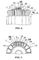
- FIG. 4 is a perspective view of the holder as viewed at one side;
- FIG. 5 is a perspective view of the holder as viewed at another side;
- FIG. 6 illustrates the thermally-actuated switch mounted on the coil end as viewed from the inner circumference of the coil;
- FIG. 7 is a top view of the thermally-actuated switch mounted on the coil end; and
- FIG. 8 is a view similar to FIG. 3, showing the thermally-actuated switch in accordance with a second embodiment of the present invention.
- The present invention will be described in more detail with reference to the accompanying drawings. A first embodiment of the invention will be described with reference to FIGS. 1 to 7. FIGS. 1 to 3 show an overall construction of the thermally-actuated switch in accordance with the embodiment, FIGS. 4 and 5 show a holder of the thermally-actuated switch, FIGS. 6 and 7 show the thermally-actuated switch mounted on a coil end.
- Referring to FIGS. 1 to 3, the thermally-actuated
switch 1 comprises aswitch body 2 and aholder 3. Theswitch body 2 includes a metallic pressure-tighthermetic container 4 and a contact mechanism (not shown) provided in thecontainer 4. The contact mechanism opens and closes contacts by a thermally-actuated member such as bimetal. - Two electrically
conductive terminals 5 protrude from one end face of thecontainer 4. Theterminals 5 extend through through-holes (not shown) formed in an end of thecontainer 4. A gap between eachterminal 5 and the corresponding through-hole is filled with an electrically insulatingfiller 6 such as glass, whereupon the eachterminal 5 is hermetically fixed to thecontainer 4.Lead wires 7 are conductively fixed to theterminals 5 by welding or the like respectively. - The
holder 3 is made of an electrically insulating material such as synthetic resin, ceramics or the like. Theholder 3 includes a flat plate-shaped base 3A and aholding portion 3B standing on one of sides or an upper side of thebase 3A. The other side or underside of thebase 3A serves as a mountingface 3L. - The
base 3A has a thickness set at about 2 mm in order that a sufficient strength and heat insulation may be obtained from thebase 3A. Thebase 3A includes amount portion 3M on which theholding portion 3B stands and on which theswitch body 2 is mounted and taperedfixing portions 3C provided on both ends of themount portion 3M respectively. Themount portion 3M is large enough to prevent theswitch body 2 mounted thereon from extending out of the mount portion. In the embodiment, themount portion 3M and fixingportions 3C or theentire base 3A serves as a heat-shielding portion. - Two
protruding bars 3J are provided on the upper side of themount portion 3M. Further, aninsertion protrusion 3K is provided on the underside of themount portion 3M for temporarily fixing theholder 3 to a coil end of an electric motor 10 (see FIGS. 6 and 7). A convexengaging portion 3D is provided on a distal end of thefixing portion 3C. The fixingportion 3C is constructed to be inclined to one side toward the distal end so as to conform to an annular shape of thecoil end 11 when thebase 3A (holder 3) is fixed to thecoil end 11 of the motor 10 (see FIGS. 6 and 7). Particularly in the embodiment, the fixingportion 3C includes lower and upper side portions disposed at inner and outer circumferential sides of the motor coil respectively. The lower and upper side portions of each fixingportion 3C have different inclinations (see FIG. 2). As a result, thebase 3A can be disposed on the coil end without extending out of the upper side of the coil end even though various coil ends have different diameters. - The holding
portion 3B includes awall 3N substantially perpendicular to thebase 3A and aflange 3F formed on an upper end and both sides of thewall 3N. Thewall 3N is formed with an elliptic through-hole 3E through which theterminals 5 extend. The through-hole 3E is rendered as large as possible in order that heat exchange may desirably be carried out between a refrigerant and thecontainer 4. A downwardly extendingprotrusion 3H is provided on an upper inner peripheral edge of the through-hole 3E.Convex engaging portions 3G are formed on both ends of the top of theflange 3F respectively. - The
switch body 2 is fixed to theholder 3 as described above in the following manner. Theterminals 5 are inserted through the through-hole 3E and one end of thecontainer 4 is abutted against thewall 3N. As a result, the end of thecontainer 4 is fitted into the holdingportion 3B. At this time, theprotrusion 3H is disposed between the twoterminals 5. Further, a space through which the refrigerant can flow is defined between thecontainer 4 and themount portion 3M by the protruding bars 3J. - Continuously, the
lead wires 7 are fixed to theterminals 5 of theswitch body 2 set in theholder 3 respectively, whereupon thelead wires 7 abut the end of thecontainer 4 against thewall 3N relatively harder such that theswitch body 2 is fixed to theholder 3. Although theswitch body 2 is incompletely fixed to theholder 3 in this state, theswitch body 2 can sufficiently be prevented from falling off from theholder 3 when the thermally-actuatedswitch 1 is mounted on the coil end as will be described later. Further, since theprotrusion 3H is located between theterminals 5, theprotrusion 3H is surrounded by theterminals 5,container 4 and leadwires 7. Accordingly, theswitch body 2 is held while positioned relative to theholder 3. - It is suggested that the
holder 3 be made of an elastic material so as to elastically hold theswitch holder 3. However, theholder 3 necessitates a heat resistance and resistance to the refrigerant. When theholder 3 further necessitates elasticity, too, a range of choice is narrowed regarding the material for theholder 3. On the other hand, no elasticity is required of theholder 3 as the result of the above-described construction in the foregoing embodiment. Consequently, the freedom in a range of choice is increased regarding the material for theholder 3. - Mounting the thermally-actuated
switch 1 on thecoil end 11 will now be described with reference to FIGS. 6 and 7. Firstly, the thermally-actuatedswitch 1 is placed on thecoil end 11 of themotor 10 so that the mountingface 3L of thebase 3A abuts against the upper side of thecoil end 11. At this time, theinsertion protrusion 3K is inserted into the space between the windings of thecoil end 11, whereby the thermally-actuatedswitch 1 is temporarily fixed to thecoil end 11. - The thermally-actuated
switch 1 temporarily fixed to thecoil end 11 is further fixed by afastening string 12 made from polyester or the like. At this time, thefastening string 12 hung on the thermally-actuatedswitch 1 is prevented from detaching from theholder 3 by the engagingportions switch 1 is thus fixed to thecoil end 11, thebase 3A is positioned between theswitch body 2 and thecoil end 11. Moreover, thebase 3A is sized so that theswitch body 2 disposed on the upper side of thebase 3A is prevented from protruding from thecoil end 11 and so that theswitch body 2 is shielded from radiant heat from thecoil end 11. Consequently, a conductive heat and radiant heat from the coil end can be prevented from directly reaching theswitch body 2. - Furthermore, the
base 3A is formed into the shape of a flat plate and a portion of thebase 3A covering theswitch body 2 is reduced as much as possible. Consequently, heat exchange between theswitch body 2 and the refrigerant can be carried out easily while theswitch body 2 is shielded from the radiant heat from thecoil end 11. - Furthermore, the through-
hole 3E is rendered as large as possible so that theswitch body 2 is readily brought into contact with the refrigerant. Further, the protrudingbars 3J are provided on the upper side of themount portion 3M so that the space through which the refrigerant flows is secured between thecontainer 4 and thebase 3A. Accordingly, since the heat exchange is efficiently carried out between thecontainer 4 and the refrigerant, the thermally-actuatedswitch 1 can quickly respond to the changes in the temperature of the refrigerant. - Furthermore, since the thickness of the
holder 3 is increased and the space is secured between thecoil end 11 and thebase 3A, heat from thecoil end 11 is less transferable via thebase 3A to theswitch body 2. Consequently, theswitch body 2 can be prevented from an excessive response to a temporary and sudden temperature increase due to a short-period overload condition not requiring heat generation and protection of thecoil end 11 during a normal operation, for example. - Additionally, the
base 3A is constructed so as to conform to the flat shape of thecoil end 11 and the thermally-actuatedswitch 1 is constructed so as not to protrude from thebase 3A. Consequently, the thermally-actuatedswitch 1 can be prevented from protruding from thecoil end 11 to interfere with the hermetic housing of the compressor. - FIG. 8 illustrates a second embodiment of the invention. Only the difference of the first and second embodiments will be described. In the second embodiment, identical or similar parts are labeled by the same reference symbols as those in the first embodiment. The thermally-actuated
switch 21 of the second embodiment is provided with two through-holes 23E formed in the holdingportion 3B of theholder 3. The through-holes 23E correspond to the locations of the twoterminals 5 respectively. - Thus, since the two through-holes are provided, a
middle portion 23H located between the through-holes 23E is surrounded by theterminals 5,container 4 andlead wire 7. Accordingly, theswitch body 2 can reliably be positioned relative to theholder 3 as in the same manner and held as in the first embodiment. - Furthermore, in the embodiment, the
spacers 23L serving as upheavals are provided on themount face 3L of thebase 3C. Thespacers 23L are provided on the lower portions of the engagingportions switch 21 when thefastening string 12 is hung on the thermally-actuatedswitch 21 so that the latter is fixed. A space through which the refrigerant is allowed to flow is defined between thecoil end 11 and thebase 3A when the thermally-actuatedswitch 1 has been disposed on thecoil end 11 by thespacers 23L. Accordingly, since a contact area of thebase 3A with thecoil end 11 is reduced, heat from thecoil end 11 can further be prevented from transferring through thebase 3A to theswitch body 2. - The present invention should not be limited by the foregoing embodiments but may be modified as follows. The
base 3A may have a thickness of not less than 1 mm. Consequently, a sufficient strength and heat insulation can be achieved. - In order that the
fastening string 12 may be prevented from being detached from theholder 3, the upper sides of the holdingportion 3B and fixingportion 3C may be corrugated, instead of provision of the engagingportions - The number of terminals should not be limited to two but may be three or more. Further, the metal container may serve as the terminal.
Claims (6)
- A thermally-actuated switch which is provided on an end (11) of a motor coil of a hermetic motor-driven compressor, comprising:a switch body (2) including a metallic pressure-tight hermetic container (4), a contact mechanism provided in the container (4), and an electrically conductive terminal (5) which hermetically extends through the hermetic container (4) and to which a lead wire (7) is connected; anda holder (3) including a base (3A) which has a mounting face (3L) for the coil end (11) and is sized so as to prevent radiant heat from transferring from the coil end (11) directly to the switch body (2) and a holding portion (3B) provided on a face of the base (3A) opposed to the mounting face (3L) for holding the switch body (2), characterized in that:the base (3A) of the holder (3) has a through hole (3E) through which the terminal (5) is inserted so that the switch body (2) is fixed to the holder (3); andthe holder (3) is held between the hermetic container (4) and the lead wire (7) having been inserted through the through hole (3E).
- A thermally-actuated switch of claim 1, wherein the holder (3) includes a protrusion (3K) provided on a peripheral edge of the through hole (3E) so as to protrude into the through hole (3E) and the protrusion (3K) is held between the hermetic container (4) and the lead wire (7).
- A thermally-actuated switch of claim 2, wherein the switch body (2) is provided with at least two terminals (5) and the protrusion (3K) is located between the terminals (5).
- A thermally-actuated switch of claim 1, wherein the switch body (2) is provided with a plurality of terminals (5), the holder (3) has a plurality of through holes (23E) corresponding to the terminals (5) respectively, and the lead wires (7) are connected to the terminals (5) having been inserted through the through holes (23E) respectively so that the holder (3) is held between the hermetic container (4) and the lead wires (7) at peripheral edges of the through holes (5).
- A thermally-actuated switch of claim 1, wherein the mounting face of the base (3C) is provided with an upheaval (23L) defining a space between the mounting face (3L) and the coil end (11) so that a refrigerant is allowed to flow through the space when the holder (3) is mounted on the coil end (11).
- A thermally-actuated switch of claim 1, wherein the base (3C) is formed into a flat shape.
Applications Claiming Priority (3)
| Application Number | Priority Date | Filing Date | Title |
|---|---|---|---|
| JP2002041291 | 2002-02-19 | ||
| JP2002041291 | 2002-02-19 | ||
| PCT/JP2003/001678 WO2003071131A1 (en) | 2002-02-19 | 2003-02-17 | Thermally-actuated switch |
Publications (3)
| Publication Number | Publication Date |
|---|---|
| EP1486671A1 EP1486671A1 (en) | 2004-12-15 |
| EP1486671A4 EP1486671A4 (en) | 2005-09-14 |
| EP1486671B1 true EP1486671B1 (en) | 2008-01-23 |
Family
ID=27750462
Family Applications (1)
| Application Number | Title | Priority Date | Filing Date |
|---|---|---|---|
| EP03705253A Expired - Lifetime EP1486671B1 (en) | 2002-02-19 | 2003-02-17 | Thermally-actuated switch |
Country Status (11)
| Country | Link |
|---|---|
| US (1) | US7345571B2 (en) |
| EP (1) | EP1486671B1 (en) |
| JP (1) | JP4382493B2 (en) |
| KR (1) | KR100637974B1 (en) |
| CN (1) | CN100374721C (en) |
| AT (1) | ATE384872T1 (en) |
| AU (1) | AU2003211353A1 (en) |
| BR (2) | BRPI0307775B1 (en) |
| DE (1) | DE60318823T2 (en) |
| RU (1) | RU2301472C2 (en) |
| WO (1) | WO2003071131A1 (en) |
Families Citing this family (10)
| Publication number | Priority date | Publication date | Assignee | Title |
|---|---|---|---|---|
| JP4402719B2 (en) * | 2005-08-02 | 2010-01-20 | 株式会社生方製作所 | Temperature switch mounting structure |
| US7535136B2 (en) * | 2006-02-22 | 2009-05-19 | Emerson Electric Co. | Protector mounting apparatus for protector mounted on the windings of a motor |
| US7808363B1 (en) * | 2008-01-22 | 2010-10-05 | Cantalice John J | Overheat protection for pump |
| DE102009030353B3 (en) * | 2009-06-22 | 2010-12-02 | Hofsaess, Marcel P. | Cap for a temperature-dependent switch and method for producing a temperature-dependent switch |
| DE102009039948A1 (en) * | 2009-08-27 | 2011-03-03 | Hofsaess, Marcel P. | Temperature-dependent switch |
| JP5693138B2 (en) * | 2010-10-19 | 2015-04-01 | 三菱重工業株式会社 | Hermetic electric compressor |
| JP6259715B2 (en) * | 2014-05-30 | 2018-01-10 | Kyb株式会社 | Rotating electric machine |
| JP6241671B2 (en) * | 2014-11-25 | 2017-12-06 | 株式会社オートネットワーク技術研究所 | Mounting structure of temperature detection member to bus bar and wiring module |
| KR102092005B1 (en) * | 2018-07-05 | 2020-03-23 | 박상량 | Connector pin for guaranteeing stable contact |
| CN112787432B (en) * | 2019-11-01 | 2022-10-11 | 上海海立电器有限公司 | A base structure of a built-in protector |
Family Cites Families (42)
| Publication number | Priority date | Publication date | Assignee | Title |
|---|---|---|---|---|
| US3131322A (en) * | 1961-03-06 | 1964-04-28 | Gen Motors Corp | Thermostatic overload protector |
| US3246183A (en) * | 1962-09-12 | 1966-04-12 | Texas Instruments Inc | Electric winding protection |
| US3515917A (en) * | 1968-04-16 | 1970-06-02 | Bachman Machine Co Inc | Thermostat device housing |
| GB1326209A (en) | 1970-09-10 | 1973-08-08 | Mitsubishi Heavy Ind Ltd | Protection of electric motors against overheating |
| US3842297A (en) * | 1972-04-06 | 1974-10-15 | Smith Corp A O | Receptacle for securing a sensing element within electrical windings |
| US4250419A (en) * | 1973-04-02 | 1981-02-10 | General Electric Company | Holder for overload protector |
| US4328438A (en) * | 1973-04-02 | 1982-05-04 | General Electric Company | Holder for overload protector |
| US3959675A (en) * | 1974-06-19 | 1976-05-25 | Gould Inc. | Bobbin-flange mounted thermal protector for electric motors |
| US4028570A (en) * | 1975-06-18 | 1977-06-07 | Emerson Electric Co. | Self locking molded thermostat strap |
| DE2538085A1 (en) | 1975-08-27 | 1977-03-10 | Licentia Gmbh | Miniature motor with winding on coil former - with temp. monitored by temp. switch in thermal contact with coil |
| US4061935A (en) * | 1976-01-05 | 1977-12-06 | Tecumseh Products Company (Compressor) | Overload protector mounting apparatus |
| US4112405A (en) * | 1976-08-16 | 1978-09-05 | Mark Joseph | Coil with protection against overheating |
| US4186318A (en) * | 1977-09-22 | 1980-01-29 | General Electric Company | Prime mover and method of assembling a device thereto |
| JPS5740701Y2 (en) * | 1977-11-07 | 1982-09-07 | ||
| SU819842A2 (en) | 1977-11-14 | 1981-04-07 | Специальное Конструкторское Бюропо Приборостроению Скб Прибор | Thermal switch |
| US4163913A (en) * | 1977-12-05 | 1979-08-07 | Sundstrand Corporation | Motor protector mount |
| US4188553A (en) * | 1978-02-08 | 1980-02-12 | A. O. Smith Corporation | Pocket receptacle for securing a sensing element within electrical windings |
| US4181393A (en) * | 1978-03-17 | 1980-01-01 | Amp Incorporated | Interconnecting means for coil windings and overload protector |
| SU773775A1 (en) | 1979-04-16 | 1980-10-23 | Предприятие П/Я В-8695 | Thermosensitive switch |
| SU1181003A1 (en) | 1984-04-04 | 1985-09-23 | Предприятие П/Я В-8695 | Temperature-sensitile switch |
| US4571518A (en) * | 1984-12-12 | 1986-02-18 | Sundstrand Corporation | Temperature sensor pocket for dynamoelectric machine winding |
| US4791329A (en) * | 1986-06-16 | 1988-12-13 | Susumu Ubukata | Motor protector mounting structure for enclosed electric compressors |
| SU1501187A1 (en) | 1988-01-07 | 1989-08-15 | Предприятие П/Я В-8574 | Thermal switch |
| JPH01198244A (en) | 1988-01-29 | 1989-08-09 | Matsushita Seiko Co Ltd | Fixture for thermal fuse |
| US5032749A (en) * | 1990-01-26 | 1991-07-16 | Magnetek Universal Electric | Electric motor |
| JPH04208047A (en) | 1990-11-30 | 1992-07-29 | Matsushita Seiko Co Ltd | Temperature fuse mounting device |
| RU2026582C1 (en) | 1992-10-06 | 1995-01-09 | Владимир Иванович Котов | Thermostatic switch |
| US5515217A (en) * | 1993-09-22 | 1996-05-07 | Ubukata Industries Co., Ltd. | Thermal protector for hermetic electrically-driven compressors |
| US5723922A (en) * | 1994-05-26 | 1998-03-03 | Tecumseh Products | Compressor overload holder and method of mounting same |
| US5615071A (en) * | 1994-12-02 | 1997-03-25 | Ubukata Industries Co., Ltd. | Thermal protector for hermetic electrically-driven compressors |
| DE19505557A1 (en) * | 1995-02-18 | 1996-08-22 | Mulfingen Elektrobau Ebm | Circuit arrangement for an electric motor |
| RU2087980C1 (en) | 1996-02-20 | 1997-08-20 | Товарищество с ограниченной ответственностью Научно-производственное предприятие "УЗЭП" | Thermostatic switch of electric device |
| JPH10144A (en) | 1996-06-14 | 1998-01-06 | Kawajiyun Kk | Showcase partitioning plate |
| JPH10144189A (en) * | 1996-11-08 | 1998-05-29 | Ubukata Seisakusho:Kk | Thermally-actuated switch |
| US5903418A (en) * | 1998-02-24 | 1999-05-11 | Texas Instruments Incorporated | Overcurrent protection apparatus for refrigeration and conditioning compressor systems |
| RU2141697C1 (en) | 1998-03-16 | 1999-11-20 | Кашин Александр Николаевич | Thermostatic switch ( versions ) |
| DE19852929C1 (en) * | 1998-11-17 | 2000-03-30 | Hanning Elektro Werke | Thermal switch for protecting electromagnetic coils in electric motor has connection lugs which enter receptacles of flat pinned plugs from inner surface of end flange of coil |
| US6315528B1 (en) * | 1999-05-27 | 2001-11-13 | Scroll Technologies | Terminal connection in small area of scroll compressor and method for carrying out same |
| JP3952432B2 (en) | 1999-10-15 | 2007-08-01 | 株式会社生方製作所 | Thermally responsive switch |
| JP3600781B2 (en) * | 2000-06-06 | 2004-12-15 | 株式会社日立製作所 | Protection device for hermetic electric compressor, hermetic electric compressor and cooling system using the same |
| ITPD20010016U1 (en) * | 2001-03-01 | 2002-09-02 | Inarca Spa | DEVICE FOR THE CONNECTION AND INSULATION OF A THERMAL PROTECTOR FOR ELECTRIC WINDINGS OF MOTORS. |
| US6498560B2 (en) * | 2001-03-23 | 2002-12-24 | Emerson Electric Co. | Protector assembly and method for electrically insulating a thermally responsive protector from a motor winding of an electric motor |
-
2003
- 2003-02-17 BR BRPI0307775-6A patent/BRPI0307775B1/en unknown
- 2003-02-17 JP JP2003570005A patent/JP4382493B2/en not_active Expired - Lifetime
- 2003-02-17 KR KR1020047012834A patent/KR100637974B1/en not_active Expired - Lifetime
- 2003-02-17 BR BRPI0307775A patent/BRPI0307775A2/en active IP Right Grant
- 2003-02-17 CN CNB038041596A patent/CN100374721C/en not_active Expired - Lifetime
- 2003-02-17 AT AT03705253T patent/ATE384872T1/en not_active IP Right Cessation
- 2003-02-17 AU AU2003211353A patent/AU2003211353A1/en not_active Abandoned
- 2003-02-17 US US10/505,024 patent/US7345571B2/en not_active Expired - Lifetime
- 2003-02-17 EP EP03705253A patent/EP1486671B1/en not_active Expired - Lifetime
- 2003-02-17 WO PCT/JP2003/001678 patent/WO2003071131A1/en not_active Ceased
- 2003-02-17 DE DE60318823T patent/DE60318823T2/en not_active Expired - Lifetime
- 2003-02-17 RU RU2004127934/09A patent/RU2301472C2/en active
Also Published As
| Publication number | Publication date |
|---|---|
| JPWO2003071131A1 (en) | 2005-06-16 |
| KR100637974B1 (en) | 2006-10-23 |
| US7345571B2 (en) | 2008-03-18 |
| WO2003071131A1 (en) | 2003-08-28 |
| BRPI0307775B1 (en) | 2018-05-15 |
| JP4382493B2 (en) | 2009-12-16 |
| CN100374721C (en) | 2008-03-12 |
| AU2003211353A1 (en) | 2003-09-09 |
| EP1486671A4 (en) | 2005-09-14 |
| KR20040086402A (en) | 2004-10-08 |
| RU2301472C2 (en) | 2007-06-20 |
| DE60318823D1 (en) | 2008-03-13 |
| EP1486671A1 (en) | 2004-12-15 |
| CN1633562A (en) | 2005-06-29 |
| ATE384872T1 (en) | 2008-02-15 |
| BRPI0307775A2 (en) | 2016-11-08 |
| DE60318823T2 (en) | 2009-01-22 |
| RU2004127934A (en) | 2005-04-10 |
| US20050104710A1 (en) | 2005-05-19 |
Similar Documents
| Publication | Publication Date | Title |
|---|---|---|
| EP0676786B1 (en) | Compact protector | |
| KR101114016B1 (en) | Statror for an electric motor | |
| US4236092A (en) | Compressor motor protection | |
| JP2002516979A (en) | Hermetic cooling compressor with improved control and connection means | |
| US5615071A (en) | Thermal protector for hermetic electrically-driven compressors | |
| US7345571B2 (en) | Thermally-actuated switch | |
| KR950008981A (en) | Protectors for Hermetic Electric Compressors | |
| KR930009731B1 (en) | Protector of hermetic electric compressor and mounting method | |
| US4490704A (en) | Thermally responsive switching device | |
| US4205246A (en) | Explosion resistant overload and relay mounting for explosion resistant motor | |
| KR20050021306A (en) | A motor start relay and an electric compressor using same | |
| JP2714774B2 (en) | Protection device for hermetic electric compressor | |
| EP0385202B1 (en) | Enclosed bimetal circuit breaker | |
| US7839259B2 (en) | Mounting structure for temperature switch | |
| JP2732039B2 (en) | Protection device for hermetic electric compressor | |
| EP0769794B1 (en) | Electrical component protection device | |
| US7088563B2 (en) | Internal motor protector for hermetic compressor | |
| JP3010141B2 (en) | Protector for hermetic electric compressor | |
| KR200382927Y1 (en) | A Terminal Assembly For Hermatic Compressor | |
| KR101115690B1 (en) | Terminal assembly for hermetic compressor | |
| KR20000028827A (en) | Feeder for use in compressor | |
| JP2782168B2 (en) | Protection device for hermetic electric compressor | |
| KR200382938Y1 (en) | A Terminal Assembly For Hermatic Compressor | |
| KR200142138Y1 (en) | Construction taking away fuse at fuse holder | |
| EP0226300A1 (en) | Protective device for enclosed type motor compressor |
Legal Events
| Date | Code | Title | Description |
|---|---|---|---|
| PUAI | Public reference made under article 153(3) epc to a published international application that has entered the european phase |
Free format text: ORIGINAL CODE: 0009012 |
|
| 17P | Request for examination filed |
Effective date: 20040920 |
|
| AK | Designated contracting states |
Kind code of ref document: A1 Designated state(s): AT BE BG CH CY CZ DE DK EE ES FI FR GB GR HU IE IT LI LU MC NL PT SE SI SK TR |
|
| AX | Request for extension of the european patent |
Extension state: AL LT LV MK RO |
|
| A4 | Supplementary search report drawn up and despatched |
Effective date: 20050729 |
|
| RIC1 | Information provided on ipc code assigned before grant |
Ipc: 7H 02K 11/00 B Ipc: 7F 04B 49/10 B Ipc: 7F 04B 39/00 A Ipc: 7F 04B 39/06 B Ipc: 7H 01H 37/04 B Ipc: 7F 04B 49/06 B |
|
| 17Q | First examination report despatched |
Effective date: 20060811 |
|
| GRAP | Despatch of communication of intention to grant a patent |
Free format text: ORIGINAL CODE: EPIDOSNIGR1 |
|
| GRAS | Grant fee paid |
Free format text: ORIGINAL CODE: EPIDOSNIGR3 |
|
| GRAA | (expected) grant |
Free format text: ORIGINAL CODE: 0009210 |
|
| AK | Designated contracting states |
Kind code of ref document: B1 Designated state(s): AT BE BG CH CY CZ DE DK EE ES FI FR GB GR HU IE IT LI LU MC NL PT SE SI SK TR |
|
| REG | Reference to a national code |
Ref country code: GB Ref legal event code: FG4D |
|
| REG | Reference to a national code |
Ref country code: CH Ref legal event code: EP |
|
| REG | Reference to a national code |
Ref country code: IE Ref legal event code: FG4D |
|
| REF | Corresponds to: |
Ref document number: 60318823 Country of ref document: DE Date of ref document: 20080313 Kind code of ref document: P |
|
| NLV1 | Nl: lapsed or annulled due to failure to fulfill the requirements of art. 29p and 29m of the patents act | ||
| PG25 | Lapsed in a contracting state [announced via postgrant information from national office to epo] |
Ref country code: LI Free format text: LAPSE BECAUSE OF FAILURE TO SUBMIT A TRANSLATION OF THE DESCRIPTION OR TO PAY THE FEE WITHIN THE PRESCRIBED TIME-LIMIT Effective date: 20080123 Ref country code: CH Free format text: LAPSE BECAUSE OF FAILURE TO SUBMIT A TRANSLATION OF THE DESCRIPTION OR TO PAY THE FEE WITHIN THE PRESCRIBED TIME-LIMIT Effective date: 20080123 Ref country code: ES Free format text: LAPSE BECAUSE OF FAILURE TO SUBMIT A TRANSLATION OF THE DESCRIPTION OR TO PAY THE FEE WITHIN THE PRESCRIBED TIME-LIMIT Effective date: 20080504 Ref country code: FI Free format text: LAPSE BECAUSE OF FAILURE TO SUBMIT A TRANSLATION OF THE DESCRIPTION OR TO PAY THE FEE WITHIN THE PRESCRIBED TIME-LIMIT Effective date: 20080123 |
|
| REG | Reference to a national code |
Ref country code: CH Ref legal event code: PL |
|
| ET | Fr: translation filed | ||
| PG25 | Lapsed in a contracting state [announced via postgrant information from national office to epo] |
Ref country code: BG Free format text: LAPSE BECAUSE OF FAILURE TO SUBMIT A TRANSLATION OF THE DESCRIPTION OR TO PAY THE FEE WITHIN THE PRESCRIBED TIME-LIMIT Effective date: 20080423 Ref country code: AT Free format text: LAPSE BECAUSE OF FAILURE TO SUBMIT A TRANSLATION OF THE DESCRIPTION OR TO PAY THE FEE WITHIN THE PRESCRIBED TIME-LIMIT Effective date: 20080123 |
|
| PG25 | Lapsed in a contracting state [announced via postgrant information from national office to epo] |
Ref country code: BE Free format text: LAPSE BECAUSE OF FAILURE TO SUBMIT A TRANSLATION OF THE DESCRIPTION OR TO PAY THE FEE WITHIN THE PRESCRIBED TIME-LIMIT Effective date: 20080123 Ref country code: SI Free format text: LAPSE BECAUSE OF FAILURE TO SUBMIT A TRANSLATION OF THE DESCRIPTION OR TO PAY THE FEE WITHIN THE PRESCRIBED TIME-LIMIT Effective date: 20080123 Ref country code: PT Free format text: LAPSE BECAUSE OF FAILURE TO SUBMIT A TRANSLATION OF THE DESCRIPTION OR TO PAY THE FEE WITHIN THE PRESCRIBED TIME-LIMIT Effective date: 20080623 |
|
| PG25 | Lapsed in a contracting state [announced via postgrant information from national office to epo] |
Ref country code: NL Free format text: LAPSE BECAUSE OF FAILURE TO SUBMIT A TRANSLATION OF THE DESCRIPTION OR TO PAY THE FEE WITHIN THE PRESCRIBED TIME-LIMIT Effective date: 20080123 Ref country code: DK Free format text: LAPSE BECAUSE OF FAILURE TO SUBMIT A TRANSLATION OF THE DESCRIPTION OR TO PAY THE FEE WITHIN THE PRESCRIBED TIME-LIMIT Effective date: 20080123 Ref country code: CZ Free format text: LAPSE BECAUSE OF FAILURE TO SUBMIT A TRANSLATION OF THE DESCRIPTION OR TO PAY THE FEE WITHIN THE PRESCRIBED TIME-LIMIT Effective date: 20080123 Ref country code: SE Free format text: LAPSE BECAUSE OF FAILURE TO SUBMIT A TRANSLATION OF THE DESCRIPTION OR TO PAY THE FEE WITHIN THE PRESCRIBED TIME-LIMIT Effective date: 20080423 Ref country code: SK Free format text: LAPSE BECAUSE OF FAILURE TO SUBMIT A TRANSLATION OF THE DESCRIPTION OR TO PAY THE FEE WITHIN THE PRESCRIBED TIME-LIMIT Effective date: 20080123 Ref country code: MC Free format text: LAPSE BECAUSE OF NON-PAYMENT OF DUE FEES Effective date: 20080228 |
|
| PLBE | No opposition filed within time limit |
Free format text: ORIGINAL CODE: 0009261 |
|
| STAA | Information on the status of an ep patent application or granted ep patent |
Free format text: STATUS: NO OPPOSITION FILED WITHIN TIME LIMIT |
|
| 26N | No opposition filed |
Effective date: 20081024 |
|
| PG25 | Lapsed in a contracting state [announced via postgrant information from national office to epo] |
Ref country code: EE Free format text: LAPSE BECAUSE OF FAILURE TO SUBMIT A TRANSLATION OF THE DESCRIPTION OR TO PAY THE FEE WITHIN THE PRESCRIBED TIME-LIMIT Effective date: 20080123 Ref country code: IE Free format text: LAPSE BECAUSE OF NON-PAYMENT OF DUE FEES Effective date: 20080218 |
|
| PG25 | Lapsed in a contracting state [announced via postgrant information from national office to epo] |
Ref country code: CY Free format text: LAPSE BECAUSE OF FAILURE TO SUBMIT A TRANSLATION OF THE DESCRIPTION OR TO PAY THE FEE WITHIN THE PRESCRIBED TIME-LIMIT Effective date: 20080123 |
|
| PG25 | Lapsed in a contracting state [announced via postgrant information from national office to epo] |
Ref country code: HU Free format text: LAPSE BECAUSE OF FAILURE TO SUBMIT A TRANSLATION OF THE DESCRIPTION OR TO PAY THE FEE WITHIN THE PRESCRIBED TIME-LIMIT Effective date: 20080724 Ref country code: LU Free format text: LAPSE BECAUSE OF NON-PAYMENT OF DUE FEES Effective date: 20080217 |
|
| PG25 | Lapsed in a contracting state [announced via postgrant information from national office to epo] |
Ref country code: TR Free format text: LAPSE BECAUSE OF FAILURE TO SUBMIT A TRANSLATION OF THE DESCRIPTION OR TO PAY THE FEE WITHIN THE PRESCRIBED TIME-LIMIT Effective date: 20080123 |
|
| PG25 | Lapsed in a contracting state [announced via postgrant information from national office to epo] |
Ref country code: GR Free format text: LAPSE BECAUSE OF FAILURE TO SUBMIT A TRANSLATION OF THE DESCRIPTION OR TO PAY THE FEE WITHIN THE PRESCRIBED TIME-LIMIT Effective date: 20080424 |
|
| REG | Reference to a national code |
Ref country code: FR Ref legal event code: PLFP Year of fee payment: 14 |
|
| REG | Reference to a national code |
Ref country code: FR Ref legal event code: PLFP Year of fee payment: 15 |
|
| REG | Reference to a national code |
Ref country code: FR Ref legal event code: PLFP Year of fee payment: 16 |
|
| PGFP | Annual fee paid to national office [announced via postgrant information from national office to epo] |
Ref country code: GB Payment date: 20211222 Year of fee payment: 20 |
|
| PGFP | Annual fee paid to national office [announced via postgrant information from national office to epo] |
Ref country code: DE Payment date: 20220214 Year of fee payment: 20 |
|
| PGFP | Annual fee paid to national office [announced via postgrant information from national office to epo] |
Ref country code: IT Payment date: 20220214 Year of fee payment: 20 Ref country code: FR Payment date: 20220208 Year of fee payment: 20 |
|
| REG | Reference to a national code |
Ref country code: DE Ref legal event code: R071 Ref document number: 60318823 Country of ref document: DE |
|
| REG | Reference to a national code |
Ref country code: GB Ref legal event code: PE20 Expiry date: 20230216 |
|
| PG25 | Lapsed in a contracting state [announced via postgrant information from national office to epo] |
Ref country code: GB Free format text: LAPSE BECAUSE OF EXPIRATION OF PROTECTION Effective date: 20230216 |