EP1486392A1 - Safety device for securing horizontally loaded cylindrical goods - Google Patents
Safety device for securing horizontally loaded cylindrical goods Download PDFInfo
- Publication number
- EP1486392A1 EP1486392A1 EP04253492A EP04253492A EP1486392A1 EP 1486392 A1 EP1486392 A1 EP 1486392A1 EP 04253492 A EP04253492 A EP 04253492A EP 04253492 A EP04253492 A EP 04253492A EP 1486392 A1 EP1486392 A1 EP 1486392A1
- Authority
- EP
- European Patent Office
- Prior art keywords
- safety device
- safety
- openings
- positioning pins
- vehicle
- Prior art date
- Legal status (The legal status is an assumption and is not a legal conclusion. Google has not performed a legal analysis and makes no representation as to the accuracy of the status listed.)
- Granted
Links
- 238000000034 method Methods 0.000 claims abstract description 5
- 230000001133 acceleration Effects 0.000 description 4
- 238000010521 absorption reaction Methods 0.000 description 1
- 230000006978 adaptation Effects 0.000 description 1
- 238000010276 construction Methods 0.000 description 1
- 230000003292 diminished effect Effects 0.000 description 1
Images
Classifications
-
- B—PERFORMING OPERATIONS; TRANSPORTING
- B61—RAILWAYS
- B61D—BODY DETAILS OR KINDS OF RAILWAY VEHICLES
- B61D45/00—Means or devices for securing or supporting the cargo, including protection against shocks
- B61D45/001—Devices for fixing to walls or floors
- B61D45/003—Fixing of logs, beams, barrels, pipes, or the like
-
- B—PERFORMING OPERATIONS; TRANSPORTING
- B60—VEHICLES IN GENERAL
- B60P—VEHICLES ADAPTED FOR LOAD TRANSPORTATION OR TO TRANSPORT, TO CARRY, OR TO COMPRISE SPECIAL LOADS OR OBJECTS
- B60P7/00—Securing or covering of load on vehicles
- B60P7/06—Securing of load
- B60P7/08—Securing to the vehicle floor or sides
- B60P7/12—Securing to the vehicle floor or sides the load being tree-trunks, beams, drums, tubes, or the like
Definitions
- the invention relates to a safety device for securing horizontally loaded cylindrical goods having a wedge-like shape.
- the invention relates to a safety system comprising the safety device and one or more rails for locking the safety device.
- the invention also relates to a vehicle, in particular a freight wagon, comprising the safety system or safety device.
- Long cylindrical goods such as paper rolls are transported lying in freight wagons.
- the cylinders can be stored parallel or transverse to the longitudinal axis of the wagon.
- forces and acceleration act on the cylindrical goods in transverse, vertical and longitudinal directions, caused by the vehicle dynamics.
- movement of the cylindrical rolls in transverse direction to the vehicle driving direction can cause dangerous situations and have to be prevented or reduced to an acceptable level.
- safety devices are used in various different embodiments.
- a safety device comprising a combination of wedges and straps.
- the wedges can be inserted in openings in the wagon floor in transverse directions over the loaded goods.
- DE 297 14 344 describes a wedge mounted on an adaptor and fitted into a rail that is mounted in the wagon floor.
- the support side of the wedges is two-dimensional concave.
- a disadvantage of both prior art security devices is that the adaptation of the system to different sized loads cannot be done very accurately. Further, the positioning of the safety devices on the wagon floor allows only the securing of cylinders lying in longitudinal direction.
- a safety device for securing horizontally loaded cylindrical goods.
- the safety device having a wedge-like shape with a low and an opposite high end, comprising a floor plate, one or more positioning pins (14) attached under the floor plate, a support member, rotatably connected on the floor plate at the low end of the device over a swivel axis (13) and an adjustment device (10) connecting the support member to the floor plate at the opposite high end of the device, which adjustment device (10) is length-adjustable.
- the support plate By adjusting the length of the adjustment device the support plate can be raised or lowered at the higher end, changing the angle of the wedge shape.
- the safety device according to the invention is fully adjustable to accurately adapt to cylindrical goods of different sizes hence providing a safer securing of the goods with less risk of damaging of the goods and of the loading space in which the goods are transported.
- the safety device can be securely mounted in the locking positions without a risk of tilting out of the locking position because of longitudinal movements of the goods on accelerations of the vehicle.
- a safety system for securing horizontally loaded cylindrical goods in the loading space of a vehicle comprising a safety device according to the invention and one or more grid rails, the grid rails comprising one or more rows of openings extending over the length of the grid rail, the openings having a shape commensurate with the shape of the positioning pins of the safety device and capable of receiving said positioning pins.
- the safety system provides a flexible and a safer way of securing cylindrical goods of different sizes.
- the cylinders can be stored in both longitudinal and transverse direction, allowing a more optimal and flexible use of the loading space and increase of loading capacity of the vehicle.
- the safety system further comprises a storage closet or storing non-used safety devices to easily make loading space available in case safety devices are not needed.
- the invention relates to a vehicle, in particular a freight wagon comprising one or more safety devices or a safety system as described above and having the many advantages thereof as described above.
- the invention relates to a method of securing cylindrical goods in a loading space of a vehicle.
- the safety device comprises a floor plate, to which two positioning pins are connected, a swivel mounted convex shaped support surface and an adjustment device.
- the safety system for securing loads provides an adjustable safety device having locking possibilities in the wagon floor and preferably also storage possibilities in case of non-use in the vehicle.
- the vehicle preferably a freight wagon, is provided with one or more parallel pairs of grid rails having multiple openings, safety devices and preferably, at the head walls, storage closets accessible from inside the wagon.
- One pair of grid rails is preferably provided on both outer sides of the wagon floor and serve for receiving the positioning pins of the safety devices and secure in that way any transverse movements of longitudinally loaded cylinders. Further, these multiple openings can receive positioning pins of protection walls for the loaded goods.
- a couple of grid rails are provided that are orientated longitudinally and parallel at the inside of the outer grid rail. These inner grid rails have two kinds of openings. One type of opening is identical to those in the outer grid rails and the other is turned over 90°. In this way, cylinders lying in longitudinal direction and, additionally, cylinders lying in transverse direction can be secured.
- a closet is provided on the head wall that is accessible from the inside.
- These storage closets comprise multiple cases comprising broad bars that are connected to create mesh-like storage shelves in the wagon and have especially mounted transverse and longitudinal bars engaging the positioning pins of the safety devices.
- Figure 1 shows an adjustable safety device, comprising a floor plate (7), a support surface (8) that is adjustable over swivelling axis (13), a spindle and a spindle bolt.
- the individual joint elements are connected through rotation and translation joints. This embodiment allows a rungless adjustment of the safety device to the applicable diameter of the cylinder to be secured.
- Figure 2 shows a safety device in which the spindle and the spindle bolt are replaced by a locking element having half-circle shaped recesses (11) and a lever with positioning pins (12).
- the support surface (8) is preferably shaped convex curved in at least two dimensions, in which the curved plane is situated in the swivelling plane of the peg according to the invention.
- the support surface (8) can be curved convex in three dimensions, the additional level of curvature being relative to the first level of curvature rotated over 90°.
- This convex curved support surface has the advantage that damage to the cylindrical goods has the consequence of sharp edges at the contact points being prevented because the contact points are always rounded. Further, this reduces the risk of pushing and tilting out the safety devices out of the oval support openings of the grid rail as a consequence of longitudinal movements of the loaded goods.
- Figure 3 shows a front view of the safety device. Under the safety device, two positioning pins (14) are mounted.
- the positioning pins have a mutual distance of at least 2 x "a", wherein the multiplication factor can only be an integral multiple of "a” and "a” is the distance of two oval-shaped openings in the outward positioned grid rails (2).
- Figure 4 shows a wagon floor (1) of a freight wagon in top view.
- the floor is provided, at the left and right extremity, with a parallel grid rail (2) with oval openings (3). Additionally, the wagon is provided with a further parallel inner set of grid rails (4).
- These inner rails have at least three rows of openings, wherein the outer rows of openings (5) are turned over 90° relative to the inner row of openings and (see figure 5) have a distance of at least A (relative to each other).
- Figure 6 shows the storage cupboards that are mounted on the head walls of the freight wagon between the head wall side columns and that are accessible from inside.
- the safety devices are stored in the closets to not limit the available storage floor space.
- the storage closets have a rectangular opening facing the wagon and have a shelf-like construction.
- the horizontal and vertical joists (15) of the storage closet that border the wagon storage space have a broad flat surface with rounded edges, preferably shaped as a rectangle rod. This way, the risk of damaging the loaded goods by sharp edges is diminished and the rods can absorb, to a certain extent, pressure occurring in case of acceleration.
- the length of the adjustment device (10) can be adapted in many different ways.
- One preferred way is shown in Figure 1 showing a safety device according to the invention the adjustment device (10) comprises a spindle and a spindle bolt, the spindle or spindle bolt connected to the floor plate (7) and the other to the support member (8), rotatably mounted to allow the spindle to turn and move up or down the bolt to change the length of the adjustment device.
- the adjustment device (10) comprises two interlocking elements, one connected to floor plate (7) and the other to support member (8), one interlocking element having two or more recesses at different heights to engage and hold into a fixed position the other interlocking element.
- the safety device preferably has two or more positioning pins (14) positioned at the low end of the device.
- the device has 3 pins, preferably arranged in an even-sided triangle.
- the one or more positioning pins (14) are preferably elongate-shaped. In that way the device cannot easily tilt out of the locking position. With elongate shape are meant for example oval, rectangular or rectangular shapes with rounded edges etc.
- the safety device comprises two adjacent elongate-shaped positioning pins (14), both at the low end of the safety device and having a length axis parallel to a length axis of the safety device.
- the support member (8) preferably has a top surface that is shaped convex-curved in at least two dimensions.
- the top surface of the support member is convex in at least two dimensions to prevent damages to the loaded goods.
- the edges are preferably rounded. More preferably the surface is 3 dimensionally convex curved.
- the positioning pins of the safety devices engage locking positions in the ground floor of a loading space, for example a freight wagon.
- the locking positions in the floor can in principle be provided in many ways. For example openings with a shape commensurate with the shape of the positioning pins can be drilled into the wagon floor. Alternatively, plates can be provided locally having such openings.
- a safety system comprising a safety device as described aboveand one or more grid rails (4), the grid rails (4) comprising one or more rows of openings (5, 6) extending over the length of the grid rail, the openings having a shape commensurate with the shape of the positioning pins (14) of the safety device and capable of receiving said positioning pins.
- the safety device has two or more adjacent positioning pins (14), the distance between the openings (6) in the rail is "a” and the distance between the positioning pins of the safety device is one or more times "a”.
- the system is easy to mount into a vehicle and with only a few adjustments converts the whole loading floor suitable for cylindrical goods.
- the grid rail comprises two or more rows of openings allowing a safety device to be positioned in two or more different directions, preferably parallel and perpendicular to the length axis of the grid rail. In this way cylindrical goods can be stored in the longitudinal and transverse direction of the vehicle.
- the pattern of openings in the rows is chosen to meet the positioning pins.
- one or more positioning pins (14) of the safety device are of elongate shape and the grid rail comprises a first row of corresponding elongate-shaped openings (5), and a further second row of elongate openings (6) with the long axis of the openings perpendicular to the long axis of the openings in the first row.
- the grid rails comprise two outer rows of elongate openings (5) at a distance between the rows of two or more times "a” and, between these outer rows, one inner row of openings (6), with the openings at a distance of "a", wherein the safety device comprises two adjacent elongate positioning pins (14) at a distance corresponding to the distance between the two outer rows in the grid rail.
- the length axis of the openings in a first row is parallel, and the length axis of the openings in a second row is perpendicular to the length axis of the grid rail.
- the invention relates further to a vehicle comprising a loading space comprising one or more safety devices or a safety system as described above.
- the vehicle can be any transport vehicle like a train a truck or even a ship, but mostly is a freight wagon.
- two or more grid rails are provided for securing cylindrical goods in a longitudinal and transverse direction of the vehicle.
- the vehicle or the safety system according to the invention preferably further comprises a storage closet for storing safety devices positioned preferably at an end wall of the loading space.
- the storage closet comprises multiple cases for storing a safety device formed by bars connected to create mesh-like shelves and bars for engaging the positioning pins (14) of the safety devices to prevent them from falling out of the closet.
- the shelves may be tilted towards the back of the closet to further prevent that the safety devices fall out of the closet because of the vehicle accelerations.
- the front bars facing the loading space preferably have a broad flat surface with rounded edges.
- the invention further relates to a method for securing cylindrical goods in a loading space of a vehicle comprising providing a wedge shaped safety device having a support member adjustable to adapt the wedge shapes to match the shape of different sized cylindrical goods, the safety device further having positioning means; further providing locking means, preferably a grid rail, for engaging and locking the positioning means of the safety devices, the positioning means and locking means being spatially arranged to allow positioning of the safety device in both longitudinal and transverse direction of the vehicle.
- the invention further relates to an energy absorption element as hereinbefore described with reference to the figures 1 to 6.
Landscapes
- Engineering & Computer Science (AREA)
- Transportation (AREA)
- Mechanical Engineering (AREA)
- Vehicle Step Arrangements And Article Storage (AREA)
- Fittings On The Vehicle Exterior For Carrying Loads, And Devices For Holding Or Mounting Articles (AREA)
- Containers And Plastic Fillers For Packaging (AREA)
- Replacement Of Web Rolls (AREA)
Abstract
Description
- The invention relates toa safety device for securing horizontally loaded cylindrical goods having a wedge-like shape. In another embodiment, the invention relates to a safety system comprising the safety device and one or more rails for locking the safety device. Further, the invention also relates to a vehicle, in particular a freight wagon, comprising the safety system or safety device.
- Long cylindrical goods such as paper rolls are transported lying in freight wagons. The cylinders can be stored parallel or transverse to the longitudinal axis of the wagon. During transport, forces and acceleration act on the cylindrical goods in transverse, vertical and longitudinal directions, caused by the vehicle dynamics. In particular, movement of the cylindrical rolls in transverse direction to the vehicle driving direction can cause dangerous situations and have to be prevented or reduced to an acceptable level.
- For that purpose, safety devices are used in various different embodiments.
- In DE 299 17 373, a safety device is proposed comprising a combination of wedges and straps. The wedges can be inserted in openings in the wagon floor in transverse directions over the loaded goods. DE 297 14 344 describes a wedge mounted on an adaptor and fitted into a rail that is mounted in the wagon floor. The support side of the wedges is two-dimensional concave. A disadvantage of both prior art security devices is that the adaptation of the system to different sized loads cannot be done very accurately. Further, the positioning of the safety devices on the wagon floor allows only the securing of cylinders lying in longitudinal direction.
- There is a need for an improved safety device for securing horizontally loaded cylindrical goods. According to the invention there is provided a safety device , the safety device having a wedge-like shape with a low and an opposite high end, comprising a floor plate, one or more positioning pins (14) attached under the floor plate, a support member, rotatably connected on the floor plate at the low end of the device over a swivel axis (13) and an adjustment device (10) connecting the support member to the floor plate at the opposite high end of the device, which adjustment device (10) is length-adjustable.
- By adjusting the length of the adjustment device the support plate can be raised or lowered at the higher end, changing the angle of the wedge shape. In that way the safety device according to the invention is fully adjustable to accurately adapt to cylindrical goods of different sizes hence providing a safer securing of the goods with less risk of damaging of the goods and of the loading space in which the goods are transported. The safety device can be securely mounted in the locking positions without a risk of tilting out of the locking position because of longitudinal movements of the goods on accelerations of the vehicle.
- In another aspect of the invention there is provided a safety system for securing horizontally loaded cylindrical goods in the loading space of a vehicle comprising a safety device according to the invention and one or more grid rails, the grid rails comprising one or more rows of openings extending over the length of the grid rail, the openings having a shape commensurate with the shape of the positioning pins of the safety device and capable of receiving said positioning pins.
- The safety system provides a flexible and a safer way of securing cylindrical goods of different sizes. The cylinders can be stored in both longitudinal and transverse direction, allowing a more optimal and flexible use of the loading space and increase of loading capacity of the vehicle. In a preferred embodiment the safety system further comprises a storage closet or storing non-used safety devices to easily make loading space available in case safety devices are not needed.
- In yet another aspect, the invention relates to a vehicle, in particular a freight wagon comprising one or more safety devices or a safety system as described above and having the many advantages thereof as described above.
- In yet another aspect the invention relates to a method of securing cylindrical goods in a loading space of a vehicle.
- In one embodiment of the invention the safety device comprises a floor plate, to which two positioning pins are connected, a swivel mounted convex shaped support surface and an adjustment device.
- The safety system for securing loads according to the invention provides an adjustable safety device having locking possibilities in the wagon floor and preferably also storage possibilities in case of non-use in the vehicle. The vehicle, preferably a freight wagon, is provided with one or more parallel pairs of grid rails having multiple openings, safety devices and preferably, at the head walls, storage closets accessible from inside the wagon. One pair of grid rails is preferably provided on both outer sides of the wagon floor and serve for receiving the positioning pins of the safety devices and secure in that way any transverse movements of longitudinally loaded cylinders. Further, these multiple openings can receive positioning pins of protection walls for the loaded goods. Further, a couple of grid rails are provided that are orientated longitudinally and parallel at the inside of the outer grid rail. These inner grid rails have two kinds of openings. One type of opening is identical to those in the outer grid rails and the other is turned over 90°. In this way, cylinders lying in longitudinal direction and, additionally, cylinders lying in transverse direction can be secured.
- For the storage of the safety device in case of non-use, a closet is provided on the head wall that is accessible from the inside. These storage closets comprise multiple cases comprising broad bars that are connected to create mesh-like storage shelves in the wagon and have especially mounted transverse and longitudinal bars engaging the positioning pins of the safety devices.
- The following is a description of an embodiment of the invention given by way of example only and with reference to the appended drawings in which:
- Fig. 1 is a schematic side view of a safety device.
- Fig. 2 is a schematic side view of a safety device with an alternative adjustment device.
- Fig. 3 is a schematic front view of a safety device.
- Fig. 4 is a schematic top view of a wagon floor fitted with grid rails.
- Fig. 5 is a schematic exploded view of the grid rails of Fig 4.
- Fig. 6 is a schematic view of a storage closet.
-
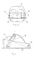
- Figure 1 shows an adjustable safety device, comprising a floor plate (7), a support surface (8) that is adjustable over swivelling axis (13), a spindle and a spindle bolt. The individual joint elements are connected through rotation and translation joints. This embodiment allows a rungless adjustment of the safety device to the applicable diameter of the cylinder to be secured.
- Figure 2 shows a safety device in which the spindle and the spindle bolt are replaced by a locking element having half-circle shaped recesses (11) and a lever with positioning pins (12). In this solution, the adjustment to the diameter of the cylinders to be stored in stepwise. Further the support surface (8) is preferably shaped convex curved in at least two dimensions, in which the curved plane is situated in the swivelling plane of the peg according to the invention. The support surface (8) can be curved convex in three dimensions, the additional level of curvature being relative to the first level of curvature rotated over 90°. This convex curved support surface has the advantage that damage to the cylindrical goods has the consequence of sharp edges at the contact points being prevented because the contact points are always rounded. Further, this reduces the risk of pushing and tilting out the safety devices out of the oval support openings of the grid rail as a consequence of longitudinal movements of the loaded goods.
- Figure 3 shows a front view of the safety device. Under the safety device, two positioning pins (14) are mounted. The positioning pins have a mutual distance of at least 2 x "a", wherein the multiplication factor can only be an integral multiple of "a" and "a" is the distance of two oval-shaped openings in the outward positioned grid rails (2).
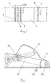
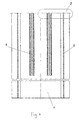
- Figure 4 shows a wagon floor (1) of a freight wagon in top view. The floor is provided, at the left and right extremity, with a parallel grid rail (2) with oval openings (3). Additionally, the wagon is provided with a further parallel inner set of grid rails (4). These inner rails have at least three rows of openings, wherein the outer rows of openings (5) are turned over 90° relative to the inner row of openings and (see figure 5) have a distance of at least A (relative to each other).
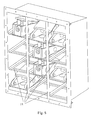
- Figure 6 shows the storage cupboards that are mounted on the head walls of the freight wagon between the head wall side columns and that are accessible from inside. In non-use, the safety devices are stored in the closets to not limit the available storage floor space. The storage closets have a rectangular opening facing the wagon and have a shelf-like construction. The horizontal and vertical joists (15) of the storage closet that border the wagon storage space have a broad flat surface with rounded edges, preferably shaped as a rectangle rod. This way, the risk of damaging the loaded goods by sharp edges is diminished and the rods can absorb, to a certain extent, pressure occurring in case of acceleration.
- The length of the adjustment device (10) can be adapted in many different ways. One preferred way is shown in Figure 1 showing a safety device according to the invention the adjustment device (10) comprises a spindle and a spindle bolt, the spindle or spindle bolt connected to the floor plate (7) and the other to the support member (8), rotatably mounted to allow the spindle to turn and move up or down the bolt to change the length of the adjustment device.
- In another embodiment the adjustment device (10) comprises two interlocking elements, one connected to floor plate (7) and the other to support member (8), one interlocking element having two or more recesses at different heights to engage and hold into a fixed position the other interlocking element.
- It is important to firmly secure the safety devices in the locking positions in the floor of the loading space. In view of that the safety device according to the invention preferably has two or more positioning pins (14) positioned at the low end of the device. In another embodiment the device has 3 pins, preferably arranged in an even-sided triangle. In the safety device the one or more positioning pins (14) are preferably elongate-shaped. In that way the device cannot easily tilt out of the locking position. With elongate shape are meant for example oval, rectangular or rectangular shapes with rounded edges etc. More preferably the safety device comprises two adjacent elongate-shaped positioning pins (14), both at the low end of the safety device and having a length axis parallel to a length axis of the safety device.
- In the safety device according to the invention the support member (8) preferably has a top surface that is shaped convex-curved in at least two dimensions. Although the overall wedge shape of the device is concave in the length direction thereof to adequately adapt to and support the cylinder shape, the top surface of the support member is convex in at least two dimensions to prevent damages to the loaded goods. In a two dimensionaly curved top surface the edges are preferably rounded. More preferably the surface is 3 dimensionally convex curved.
- The positioning pins of the safety devices engage locking positions in the ground floor of a loading space, for example a freight wagon. The locking positions in the floor can in principle be provided in many ways. For example openings with a shape commensurate with the shape of the positioning pins can be drilled into the wagon floor. Alternatively, plates can be provided locally having such openings. However in another aspect according to the invention there is provided a safety system comprising a safety device as described aboveand one or more grid rails (4), the grid rails (4) comprising one or more rows of openings (5, 6) extending over the length of the grid rail, the openings having a shape commensurate with the shape of the positioning pins (14) of the safety device and capable of receiving said positioning pins. Preferably, in the safety system the safety device has two or more adjacent positioning pins (14), the distance between the openings (6) in the rail is "a" and the distance between the positioning pins of the safety device is one or more times "a". The system is easy to mount into a vehicle and with only a few adjustments converts the whole loading floor suitable for cylindrical goods.
- In a preferred embodiment the grid rail comprises two or more rows of openings allowing a safety device to be positioned in two or more different directions, preferably parallel and perpendicular to the length axis of the grid rail. In this way cylindrical goods can be stored in the longitudinal and transverse direction of the vehicle. The pattern of openings in the rows is chosen to meet the positioning pins. Preferably, in the safety system one or more positioning pins (14) of the safety device are of elongate shape and the grid rail comprises a first row of corresponding elongate-shaped openings (5), and a further second row of elongate openings (6) with the long axis of the openings perpendicular to the long axis of the openings in the first row.
- In a preferred embodiment (see Fig 5) the grid rails comprise two outer rows of elongate openings (5) at a distance between the rows of two or more times "a" and, between these outer rows, one inner row of openings (6), with the openings at a distance of "a", wherein the safety device comprises two adjacent elongate positioning pins (14) at a distance corresponding to the distance between the two outer rows in the grid rail.
- Preferably, the length axis of the openings in a first row is parallel, and the length axis of the openings in a second row is perpendicular to the length axis of the grid rail.
- The invention relates further to a vehicle comprising a loading space comprising one or more safety devices or a safety system as described above. The vehicle can be any transport vehicle like a train a truck or even a ship, but mostly is a freight wagon. In the vehicle on the floor of the loading space, two or more grid rails are provided for securing cylindrical goods in a longitudinal and transverse direction of the vehicle.
- The vehicle or the safety system according to the invention preferably further comprises a storage closet for storing safety devices positioned preferably at an end wall of the loading space. The storage closet comprises multiple cases for storing a safety device formed by bars connected to create mesh-like shelves and bars for engaging the positioning pins (14) of the safety devices to prevent them from falling out of the closet. The shelves may be tilted towards the back of the closet to further prevent that the safety devices fall out of the closet because of the vehicle accelerations. To prevent damages to the cylindrical goods the front bars facing the loading space preferably have a broad flat surface with rounded edges.
- The invention further relates to a method for securing cylindrical goods in a loading space of a vehicle comprising providing a wedge shaped safety device having a support member adjustable to adapt the wedge shapes to match the shape of different sized cylindrical goods, the safety device further having positioning means; further providing locking means, preferably a grid rail, for engaging and locking the positioning means of the safety devices, the positioning means and locking means being spatially arranged to allow positioning of the safety device in both longitudinal and transverse direction of the vehicle.
- The scope of the invention is not limited by the specific drawings. The skilled man can easily create other embodiments of the invention within the concept as described above.
- The invention further relates to an energy absorption element as hereinbefore described with reference to the figures 1 to 6.
Claims (23)
- Safety device for securing horizontally loaded cylindrical goods, the safety device having a wedge-like shape with a low and an opposite high end, comprising:a floor plate (7);one or more positioning pins (14) attached under the floor plate (7);a support member (8), rotatably connected on the floor plate (7) at the low end of the device over a swivel axis (13); andan adjustment device (10) connecting the support member (8) to the floor plate (7) at the opposite high end of the device, which adjustment device (10) is length-adjustable.
- Safety device according to claim 1, wherein the adjustment device (10) comprises a spindle and a spindle bolt, the spindle or spindle bolt connected to the floor plate (7) and the other to the support member (8), rotatably mounted to allow the spindle to turn and move up or down the bolt to change the length of the adjustment device.
- Safety device according to claim 1, wherein the adjustment device (10) comprises two interlocking elements, one connected to floor plate (7) and the other to support member (8), one interlocking element having two or more recesses at different heights to engage and hold into a fixed position the other interlocking element.
- Safety device according to any one of claims 1 to 3, wherein two or more positioning pins (14) are positioned at the low end of the device.
- Safety device according to claim 1 to 4, wherein the one or more positioning pins (14) are elongate-shaped.
- Safety device according to claims 1 to 5, comprising two elongate-shaped positioning pins (14), both at the low end of the device and having a length axis parallel to a length axis of the safety device.
- Safety device according to claims 1 to 6, wherein the support member (8) has a top surface that is shaped convex-curved in at least two dimensions.
- Safety system comprising a safety device according to any one of claims 1 to 7 and one or more grid rails (4), the grid rails (4) comprising one or more rows of openings (5, 6) extending over the length of the grid rail, the openings having a shape commensurate with the shape of the positioning pins (14) of the safety device and capable of receiving said positioning pins.
- Safety system according to claim 8, wherein the safety device has two or more adjacent positioning pins (14), the distance between the openings (6) in the rail is "a" and the distance between the positioning pins of the safety device is one or more times "a".
- Safety system according to claims 8 or 9, wherein the grid rail comprises two or more rows of openings allowing a safety device to be positioned in two or more different directions, preferably parallel and perpendicular to the length axis of the grid rail.
- Safety system according to claim 10, wherein one or more positioning pins (14) of the safety device are of elongate shape and wherein a grid rail comprises a first row of corresponding elongate-shaped openings (5), and a further second row of elongate openings (6) with the long axis of the openings perpendicular to the long axis of the openings in the first row.
- Safety system according to claims 9, 10 or 11, wherein the grid rails comprise two outer rows of elongate openings (5) at a distance between the rows of two or more times "a" and, between these outer rows, one inner row of openings (6), with the openings at a distance of "a", wherein the safety device comprises two adjacent elongate positioning pins (14) at a distance corresponding to the distance between the two outer rows in the grid rail.
- Safety system according to claims 10 to 12, wherein the length axis of the openings in a first row is parallel, and the length axis of the openings in a second row is perpendicular to the length axis of the grid rail.
- A vehicle comprising a loading space comprising one or more safety devices according to any one of claims 1 - 8 or a safety system according to claims 9 to 13.
- A vehicle according to claim 14 comprising, on the floor of the loading space, two or more grid rails according to claims 10 to 13 for securing cylindrical goods in a longitudinal and transverse direction of the vehicle.
- A vehicle according to claims 14 or 15 further comprising, preferably at an end wall of the loading space, a storage closet for storing safety devices according to claims 1 to 8.
- Vehicle according to claim 16, wherein the storage closet comprises multiple cases for storing a safety device formed by bars connected to create mesh-like shelves and bars for engaging the positioning pins (14) of the safety devices according to any one of claims 1 to 8 to prevent them from falling out of the closet.
- Vehicle according to claim 17, wherein the front bars facing the loading space have a broad flat surface with rounded edges.
- Method for securing cylindrical goods in a loading space of a vehicle comprising providing a wedge shaped safety device having a support member adjustable to adapt the wedge shape to match the shape of different sized cylindrical goods, the safety device further having positioning means; further providing to a floor part of the loading space locking means, preferably a grid rail, for engaging and locking the positioning means of the safety devices, the positioning means and locking means being spatially arranged to allow positioning of the safety device in both longitudinal and transverse direction of the vehicle.
- A safety system substantially as hereinbefore described having reference to any one of Figures 1 to 6.
- A safety device substantially as hereinbefore described having reference to any one of Figures 1 to 6.
- A vehicle substantially as hereinbefore described having reference to any one of Figures 1 to 6.
- A method substantially as hereinbefore described having reference to any one of Figures 1 to 6.
Applications Claiming Priority (2)
| Application Number | Priority Date | Filing Date | Title |
|---|---|---|---|
| GBGB0313729.6A GB0313729D0 (en) | 2003-06-13 | 2003-06-13 | Safety device for securing horizontally loaded cylindrical goods |
| GB0313729 | 2003-06-13 |
Publications (2)
| Publication Number | Publication Date |
|---|---|
| EP1486392A1 true EP1486392A1 (en) | 2004-12-15 |
| EP1486392B1 EP1486392B1 (en) | 2007-03-21 |
Family
ID=27590061
Family Applications (1)
| Application Number | Title | Priority Date | Filing Date |
|---|---|---|---|
| EP04253492A Expired - Lifetime EP1486392B1 (en) | 2003-06-13 | 2004-06-11 | Safety device for securing horizontally loaded cylindrical goods |
Country Status (4)
| Country | Link |
|---|---|
| EP (1) | EP1486392B1 (en) |
| AT (1) | ATE357360T1 (en) |
| DE (1) | DE602004005377T2 (en) |
| GB (1) | GB0313729D0 (en) |
Families Citing this family (2)
| Publication number | Priority date | Publication date | Assignee | Title |
|---|---|---|---|---|
| DE102012218762A1 (en) | 2012-09-06 | 2014-03-06 | Burg Silvergreen Gmbh | DEVICE FOR SECURING LOADEGUT |
| CN112249064A (en) * | 2020-10-26 | 2021-01-22 | 中车眉山车辆有限公司 | Variable angle baffle is constituteed |
Citations (6)
| Publication number | Priority date | Publication date | Assignee | Title |
|---|---|---|---|---|
| US3074512A (en) * | 1958-12-12 | 1963-01-22 | Arthur G S Naur | Supporting device or adjustable wedge for rollable objects |
| US4217831A (en) * | 1978-12-01 | 1980-08-19 | General Motors Corporation | Chock device for a transporting vehicle |
| EP0017599A1 (en) * | 1979-02-27 | 1980-10-15 | Etablissements Françon et Cie (société anonyme) | Floor of transport vehicle comprising a load wedging device |
| EP0344661A1 (en) * | 1988-05-31 | 1989-12-06 | Rautaruukki Oy | A wheel chock |
| DE29714344U1 (en) | 1997-08-20 | 1997-12-11 | Käßmeyer Fördertechnik Vertriebsges. mbH, 89250 Senden | Adapter for load securing wedge in recessed rails for vehicles |
| DE29917373U1 (en) | 1999-10-04 | 2001-02-15 | Rail & Sea Speditions-Gmbh, Strasswalchen | Freight wagons with load securing, especially for jumbo gravure rolls |
-
2003
- 2003-06-13 GB GBGB0313729.6A patent/GB0313729D0/en not_active Ceased
-
2004
- 2004-06-11 AT AT04253492T patent/ATE357360T1/en not_active IP Right Cessation
- 2004-06-11 DE DE602004005377T patent/DE602004005377T2/en not_active Expired - Fee Related
- 2004-06-11 EP EP04253492A patent/EP1486392B1/en not_active Expired - Lifetime
Patent Citations (6)
| Publication number | Priority date | Publication date | Assignee | Title |
|---|---|---|---|---|
| US3074512A (en) * | 1958-12-12 | 1963-01-22 | Arthur G S Naur | Supporting device or adjustable wedge for rollable objects |
| US4217831A (en) * | 1978-12-01 | 1980-08-19 | General Motors Corporation | Chock device for a transporting vehicle |
| EP0017599A1 (en) * | 1979-02-27 | 1980-10-15 | Etablissements Françon et Cie (société anonyme) | Floor of transport vehicle comprising a load wedging device |
| EP0344661A1 (en) * | 1988-05-31 | 1989-12-06 | Rautaruukki Oy | A wheel chock |
| DE29714344U1 (en) | 1997-08-20 | 1997-12-11 | Käßmeyer Fördertechnik Vertriebsges. mbH, 89250 Senden | Adapter for load securing wedge in recessed rails for vehicles |
| DE29917373U1 (en) | 1999-10-04 | 2001-02-15 | Rail & Sea Speditions-Gmbh, Strasswalchen | Freight wagons with load securing, especially for jumbo gravure rolls |
Also Published As
| Publication number | Publication date |
|---|---|
| EP1486392B1 (en) | 2007-03-21 |
| DE602004005377T2 (en) | 2008-06-19 |
| ATE357360T1 (en) | 2007-04-15 |
| DE602004005377D1 (en) | 2007-05-03 |
| GB0313729D0 (en) | 2003-07-16 |
Similar Documents
| Publication | Publication Date | Title |
|---|---|---|
| ES3055552T3 (en) | A grid levelling mechanism | |
| ES2966221T3 (en) | Battery block movement set | |
| ES2751302T3 (en) | Transport and storage system for wind turbine blades | |
| AU2003219416C1 (en) | Transport container for wind turbine blades | |
| US8807891B2 (en) | Removable frame systems for vehicle shipping | |
| US4648764A (en) | Portable stacking containers locking device | |
| US8151714B2 (en) | Container support for freight wagon | |
| US8740526B2 (en) | Load beam assembly | |
| JPWO2005035397A1 (en) | Freight rack | |
| EP1486392B1 (en) | Safety device for securing horizontally loaded cylindrical goods | |
| ES2364961T3 (en) | TRANSPORT VEHICLES. | |
| EP4301686B1 (en) | Layover bracket system | |
| WO2008142202A2 (en) | Method and stand for loading reels onboard a ship and shipping arrangement | |
| EP3496985B1 (en) | Transportation unit transfer system with rail alignment means | |
| EP0105754A2 (en) | A rack and a method for storing wheeled container chassis | |
| FR3011536A1 (en) | CONTAINER FOR STORAGE AND TRANSPORT OF GOODS | |
| ES2334153T3 (en) | TICKET BOX STRUCTURE FOR GOODS TRANSPORT VEHICLES. | |
| CN121180260B (en) | Rail plate conveying device | |
| ES2308337T3 (en) | ARTICULATION FOR THE POSTS OF A TRANSPORTATION AND STORAGE FRAME. | |
| ES2331419T3 (en) | A CARGO TRANSPORTATION VEHICLE. | |
| KR101236125B1 (en) | storage apparatus for roll | |
| ES2348650T3 (en) | TRAILER FOR CONTAINER TRANSPORTATION BY ROAD. | |
| EP4122839B1 (en) | Storage module for the stacked storage of semi-trailers and / or large-capacity containers | |
| RU2763618C1 (en) | Device for fixing containers on the platform | |
| WO2002042115A1 (en) | Transportation system for containers, transportation frame and method |
Legal Events
| Date | Code | Title | Description |
|---|---|---|---|
| PUAI | Public reference made under article 153(3) epc to a published international application that has entered the european phase |
Free format text: ORIGINAL CODE: 0009012 |
|
| AK | Designated contracting states |
Kind code of ref document: A1 Designated state(s): AT BE BG CH CY CZ DE DK EE ES FI FR GB GR HU IE IT LI LU MC NL PL PT RO SE SI SK TR |
|
| AX | Request for extension of the european patent |
Extension state: AL HR LT LV MK |
|
| RAP1 | Party data changed (applicant data changed or rights of an application transferred) |
Owner name: RAILION DEUTSCHLAND AG Owner name: BOMBARDIER TRANSPORTATION (TECHNOLOGY) GERMANY GMB |
|
| 17P | Request for examination filed |
Effective date: 20050525 |
|
| AKX | Designation fees paid |
Designated state(s): AT BE BG CH CY CZ DE DK EE ES FI FR GB GR HU IE IT LI LU MC NL PL PT RO SE SI SK TR |
|
| AXX | Extension fees paid |
Extension state: AL Payment date: 20050615 Extension state: LT Payment date: 20050615 Extension state: MK Payment date: 20050615 Extension state: LV Payment date: 20050615 Extension state: HR Payment date: 20050615 |
|
| RAP1 | Party data changed (applicant data changed or rights of an application transferred) |
Owner name: RAILION DEUTSCHLAND AG |
|
| GRAP | Despatch of communication of intention to grant a patent |
Free format text: ORIGINAL CODE: EPIDOSNIGR1 |
|
| GRAS | Grant fee paid |
Free format text: ORIGINAL CODE: EPIDOSNIGR3 |
|
| GRAA | (expected) grant |
Free format text: ORIGINAL CODE: 0009210 |
|
| AK | Designated contracting states |
Kind code of ref document: B1 Designated state(s): AT BE BG CH CY CZ DE DK EE ES FI FR GB GR HU IE IT LI LU MC NL PL PT RO SE SI SK TR |
|
| AX | Request for extension of the european patent |
Extension state: AL HR LT LV MK |
|
| PG25 | Lapsed in a contracting state [announced via postgrant information from national office to epo] |
Ref country code: CH Free format text: LAPSE BECAUSE OF FAILURE TO SUBMIT A TRANSLATION OF THE DESCRIPTION OR TO PAY THE FEE WITHIN THE PRESCRIBED TIME-LIMIT Effective date: 20070321 Ref country code: SI Free format text: LAPSE BECAUSE OF FAILURE TO SUBMIT A TRANSLATION OF THE DESCRIPTION OR TO PAY THE FEE WITHIN THE PRESCRIBED TIME-LIMIT Effective date: 20070321 Ref country code: AT Free format text: LAPSE BECAUSE OF FAILURE TO SUBMIT A TRANSLATION OF THE DESCRIPTION OR TO PAY THE FEE WITHIN THE PRESCRIBED TIME-LIMIT Effective date: 20070321 Ref country code: NL Free format text: LAPSE BECAUSE OF FAILURE TO SUBMIT A TRANSLATION OF THE DESCRIPTION OR TO PAY THE FEE WITHIN THE PRESCRIBED TIME-LIMIT Effective date: 20070321 Ref country code: PL Free format text: LAPSE BECAUSE OF FAILURE TO SUBMIT A TRANSLATION OF THE DESCRIPTION OR TO PAY THE FEE WITHIN THE PRESCRIBED TIME-LIMIT Effective date: 20070321 Ref country code: BE Free format text: LAPSE BECAUSE OF FAILURE TO SUBMIT A TRANSLATION OF THE DESCRIPTION OR TO PAY THE FEE WITHIN THE PRESCRIBED TIME-LIMIT Effective date: 20070321 Ref country code: LI Free format text: LAPSE BECAUSE OF FAILURE TO SUBMIT A TRANSLATION OF THE DESCRIPTION OR TO PAY THE FEE WITHIN THE PRESCRIBED TIME-LIMIT Effective date: 20070321 |
|
| REG | Reference to a national code |
Ref country code: GB Ref legal event code: FG4D |
|
| REG | Reference to a national code |
Ref country code: CH Ref legal event code: EP |
|
| REF | Corresponds to: |
Ref document number: 602004005377 Country of ref document: DE Date of ref document: 20070503 Kind code of ref document: P |
|
| REG | Reference to a national code |
Ref country code: IE Ref legal event code: FG4D |
|
| PG25 | Lapsed in a contracting state [announced via postgrant information from national office to epo] |
Ref country code: SE Free format text: LAPSE BECAUSE OF FAILURE TO SUBMIT A TRANSLATION OF THE DESCRIPTION OR TO PAY THE FEE WITHIN THE PRESCRIBED TIME-LIMIT Effective date: 20070621 |
|
| PG25 | Lapsed in a contracting state [announced via postgrant information from national office to epo] |
Ref country code: ES Free format text: LAPSE BECAUSE OF FAILURE TO SUBMIT A TRANSLATION OF THE DESCRIPTION OR TO PAY THE FEE WITHIN THE PRESCRIBED TIME-LIMIT Effective date: 20070702 |
|
| PG25 | Lapsed in a contracting state [announced via postgrant information from national office to epo] |
Ref country code: PT Free format text: LAPSE BECAUSE OF FAILURE TO SUBMIT A TRANSLATION OF THE DESCRIPTION OR TO PAY THE FEE WITHIN THE PRESCRIBED TIME-LIMIT Effective date: 20070821 |
|
| LTIE | Lt: invalidation of european patent or patent extension |
Effective date: 20070321 |
|
| REG | Reference to a national code |
Ref country code: CH Ref legal event code: PL |
|
| NLV1 | Nl: lapsed or annulled due to failure to fulfill the requirements of art. 29p and 29m of the patents act | ||
| EN | Fr: translation not filed | ||
| PG25 | Lapsed in a contracting state [announced via postgrant information from national office to epo] |
Ref country code: SK Free format text: LAPSE BECAUSE OF FAILURE TO SUBMIT A TRANSLATION OF THE DESCRIPTION OR TO PAY THE FEE WITHIN THE PRESCRIBED TIME-LIMIT Effective date: 20070321 |
|
| PG25 | Lapsed in a contracting state [announced via postgrant information from national office to epo] |
Ref country code: CZ Free format text: LAPSE BECAUSE OF FAILURE TO SUBMIT A TRANSLATION OF THE DESCRIPTION OR TO PAY THE FEE WITHIN THE PRESCRIBED TIME-LIMIT Effective date: 20070321 Ref country code: RO Free format text: LAPSE BECAUSE OF FAILURE TO SUBMIT A TRANSLATION OF THE DESCRIPTION OR TO PAY THE FEE WITHIN THE PRESCRIBED TIME-LIMIT Effective date: 20070321 |
|
| PLBE | No opposition filed within time limit |
Free format text: ORIGINAL CODE: 0009261 |
|
| STAA | Information on the status of an ep patent application or granted ep patent |
Free format text: STATUS: NO OPPOSITION FILED WITHIN TIME LIMIT |
|
| PG25 | Lapsed in a contracting state [announced via postgrant information from national office to epo] |
Ref country code: DK Free format text: LAPSE BECAUSE OF FAILURE TO SUBMIT A TRANSLATION OF THE DESCRIPTION OR TO PAY THE FEE WITHIN THE PRESCRIBED TIME-LIMIT Effective date: 20070321 Ref country code: MC Free format text: LAPSE BECAUSE OF NON-PAYMENT OF DUE FEES Effective date: 20070630 Ref country code: DE Free format text: LAPSE BECAUSE OF FAILURE TO SUBMIT A TRANSLATION OF THE DESCRIPTION OR TO PAY THE FEE WITHIN THE PRESCRIBED TIME-LIMIT Effective date: 20070622 |
|
| 26N | No opposition filed |
Effective date: 20071227 |
|
| PG25 | Lapsed in a contracting state [announced via postgrant information from national office to epo] |
Ref country code: FR Free format text: LAPSE BECAUSE OF FAILURE TO SUBMIT A TRANSLATION OF THE DESCRIPTION OR TO PAY THE FEE WITHIN THE PRESCRIBED TIME-LIMIT Effective date: 20071123 Ref country code: GR Free format text: LAPSE BECAUSE OF FAILURE TO SUBMIT A TRANSLATION OF THE DESCRIPTION OR TO PAY THE FEE WITHIN THE PRESCRIBED TIME-LIMIT Effective date: 20070622 Ref country code: IT Free format text: LAPSE BECAUSE OF FAILURE TO SUBMIT A TRANSLATION OF THE DESCRIPTION OR TO PAY THE FEE WITHIN THE PRESCRIBED TIME-LIMIT Effective date: 20070321 |
|
| PGRI | Patent reinstated in contracting state [announced from national office to epo] |
Ref country code: DE Effective date: 20080318 |
|
| PG25 | Lapsed in a contracting state [announced via postgrant information from national office to epo] |
Ref country code: IE Free format text: LAPSE BECAUSE OF NON-PAYMENT OF DUE FEES Effective date: 20070611 |
|
| PGFP | Annual fee paid to national office [announced via postgrant information from national office to epo] |
Ref country code: DE Payment date: 20080630 Year of fee payment: 5 |
|
| PG25 | Lapsed in a contracting state [announced via postgrant information from national office to epo] |
Ref country code: FR Free format text: LAPSE BECAUSE OF FAILURE TO SUBMIT A TRANSLATION OF THE DESCRIPTION OR TO PAY THE FEE WITHIN THE PRESCRIBED TIME-LIMIT Effective date: 20070321 |
|
| PG25 | Lapsed in a contracting state [announced via postgrant information from national office to epo] |
Ref country code: EE Free format text: LAPSE BECAUSE OF FAILURE TO SUBMIT A TRANSLATION OF THE DESCRIPTION OR TO PAY THE FEE WITHIN THE PRESCRIBED TIME-LIMIT Effective date: 20070321 |
|
| GBPC | Gb: european patent ceased through non-payment of renewal fee |
Effective date: 20080611 |
|
| PG25 | Lapsed in a contracting state [announced via postgrant information from national office to epo] |
Ref country code: GB Free format text: LAPSE BECAUSE OF NON-PAYMENT OF DUE FEES Effective date: 20080611 |
|
| PG25 | Lapsed in a contracting state [announced via postgrant information from national office to epo] |
Ref country code: CY Free format text: LAPSE BECAUSE OF FAILURE TO SUBMIT A TRANSLATION OF THE DESCRIPTION OR TO PAY THE FEE WITHIN THE PRESCRIBED TIME-LIMIT Effective date: 20070321 |
|
| PG25 | Lapsed in a contracting state [announced via postgrant information from national office to epo] |
Ref country code: LU Free format text: LAPSE BECAUSE OF NON-PAYMENT OF DUE FEES Effective date: 20070611 Ref country code: FI Free format text: LAPSE BECAUSE OF FAILURE TO SUBMIT A TRANSLATION OF THE DESCRIPTION OR TO PAY THE FEE WITHIN THE PRESCRIBED TIME-LIMIT Effective date: 20070321 Ref country code: BG Free format text: LAPSE BECAUSE OF FAILURE TO SUBMIT A TRANSLATION OF THE DESCRIPTION OR TO PAY THE FEE WITHIN THE PRESCRIBED TIME-LIMIT Effective date: 20070621 |
|
| PG25 | Lapsed in a contracting state [announced via postgrant information from national office to epo] |
Ref country code: HU Free format text: LAPSE BECAUSE OF FAILURE TO SUBMIT A TRANSLATION OF THE DESCRIPTION OR TO PAY THE FEE WITHIN THE PRESCRIBED TIME-LIMIT Effective date: 20070922 Ref country code: TR Free format text: LAPSE BECAUSE OF FAILURE TO SUBMIT A TRANSLATION OF THE DESCRIPTION OR TO PAY THE FEE WITHIN THE PRESCRIBED TIME-LIMIT Effective date: 20070321 |
|
| PG25 | Lapsed in a contracting state [announced via postgrant information from national office to epo] |
Ref country code: DE Free format text: LAPSE BECAUSE OF NON-PAYMENT OF DUE FEES Effective date: 20100101 |