EP1486184A1 - Automatic urine disposal device and urine receptacle used therefor - Google Patents
Automatic urine disposal device and urine receptacle used therefor Download PDFInfo
- Publication number
- EP1486184A1 EP1486184A1 EP04013652A EP04013652A EP1486184A1 EP 1486184 A1 EP1486184 A1 EP 1486184A1 EP 04013652 A EP04013652 A EP 04013652A EP 04013652 A EP04013652 A EP 04013652A EP 1486184 A1 EP1486184 A1 EP 1486184A1
- Authority
- EP
- European Patent Office
- Prior art keywords
- urine
- sheet
- receptacle
- perforated
- tank
- Prior art date
- Legal status (The legal status is an assumption and is not a legal conclusion. Google has not performed a legal analysis and makes no representation as to the accuracy of the status listed.)
- Withdrawn
Links
- 210000002700 urine Anatomy 0.000 title claims abstract description 360
- 239000002250 absorbent Substances 0.000 claims abstract description 61
- 230000002745 absorbent Effects 0.000 claims abstract description 59
- 239000011148 porous material Substances 0.000 claims description 25
- 230000007423 decrease Effects 0.000 claims description 4
- 239000002657 fibrous material Substances 0.000 claims description 3
- 230000003213 activating effect Effects 0.000 claims 1
- 238000007789 sealing Methods 0.000 claims 1
- 239000000463 material Substances 0.000 description 14
- 239000004744 fabric Substances 0.000 description 7
- -1 polyethylene Polymers 0.000 description 5
- 230000002093 peripheral effect Effects 0.000 description 4
- 239000004698 Polyethylene Substances 0.000 description 3
- 230000027939 micturition Effects 0.000 description 3
- 229920000573 polyethylene Polymers 0.000 description 3
- 230000002035 prolonged effect Effects 0.000 description 3
- 125000000391 vinyl group Chemical group [H]C([*])=C([H])[H] 0.000 description 3
- 229920002554 vinyl polymer Polymers 0.000 description 3
- 239000004743 Polypropylene Substances 0.000 description 2
- 150000001875 compounds Chemical class 0.000 description 2
- 238000001514 detection method Methods 0.000 description 2
- 238000010586 diagram Methods 0.000 description 2
- 230000003340 mental effect Effects 0.000 description 2
- 229920001155 polypropylene Polymers 0.000 description 2
- 239000011347 resin Substances 0.000 description 2
- 229920005989 resin Polymers 0.000 description 2
- 239000007779 soft material Substances 0.000 description 2
- 238000012360 testing method Methods 0.000 description 2
- 239000012808 vapor phase Substances 0.000 description 2
- 229920000742 Cotton Polymers 0.000 description 1
- 208000010201 Exanthema Diseases 0.000 description 1
- 208000027418 Wounds and injury Diseases 0.000 description 1
- 238000010521 absorption reaction Methods 0.000 description 1
- 210000001217 buttock Anatomy 0.000 description 1
- 230000006378 damage Effects 0.000 description 1
- 230000013872 defecation Effects 0.000 description 1
- 230000000694 effects Effects 0.000 description 1
- 239000013013 elastic material Substances 0.000 description 1
- 201000005884 exanthem Diseases 0.000 description 1
- 239000000835 fiber Substances 0.000 description 1
- 239000006260 foam Substances 0.000 description 1
- 208000015181 infectious disease Diseases 0.000 description 1
- 208000014674 injury Diseases 0.000 description 1
- 239000007788 liquid Substances 0.000 description 1
- 238000000034 method Methods 0.000 description 1
- 238000000465 moulding Methods 0.000 description 1
- 230000037081 physical activity Effects 0.000 description 1
- 229920000728 polyester Polymers 0.000 description 1
- 229920000642 polymer Polymers 0.000 description 1
- 229920000098 polyolefin Polymers 0.000 description 1
- 206010037844 rash Diseases 0.000 description 1
- 239000005871 repellent Substances 0.000 description 1
- 239000004753 textile Substances 0.000 description 1
- 210000003708 urethra Anatomy 0.000 description 1
- 238000009736 wetting Methods 0.000 description 1
Images

Classifications
-
- A—HUMAN NECESSITIES
- A61—MEDICAL OR VETERINARY SCIENCE; HYGIENE
- A61F—FILTERS IMPLANTABLE INTO BLOOD VESSELS; PROSTHESES; DEVICES PROVIDING PATENCY TO, OR PREVENTING COLLAPSING OF, TUBULAR STRUCTURES OF THE BODY, e.g. STENTS; ORTHOPAEDIC, NURSING OR CONTRACEPTIVE DEVICES; FOMENTATION; TREATMENT OR PROTECTION OF EYES OR EARS; BANDAGES, DRESSINGS OR ABSORBENT PADS; FIRST-AID KITS
- A61F13/00—Bandages or dressings; Absorbent pads
- A61F13/15—Absorbent pads, e.g. sanitary towels, swabs or tampons for external or internal application to the body; Supporting or fastening means therefor; Tampon applicators
- A61F13/53—Absorbent pads, e.g. sanitary towels, swabs or tampons for external or internal application to the body; Supporting or fastening means therefor; Tampon applicators characterised by the absorbing medium
- A61F13/534—Absorbent pads, e.g. sanitary towels, swabs or tampons for external or internal application to the body; Supporting or fastening means therefor; Tampon applicators characterised by the absorbing medium having an inhomogeneous composition through the thickness of the pad
- A61F13/535—Absorbent pads, e.g. sanitary towels, swabs or tampons for external or internal application to the body; Supporting or fastening means therefor; Tampon applicators characterised by the absorbing medium having an inhomogeneous composition through the thickness of the pad inhomogeneous in the plane of the pad, e.g. core absorbent layers being of different sizes
-
- A—HUMAN NECESSITIES
- A61—MEDICAL OR VETERINARY SCIENCE; HYGIENE
- A61F—FILTERS IMPLANTABLE INTO BLOOD VESSELS; PROSTHESES; DEVICES PROVIDING PATENCY TO, OR PREVENTING COLLAPSING OF, TUBULAR STRUCTURES OF THE BODY, e.g. STENTS; ORTHOPAEDIC, NURSING OR CONTRACEPTIVE DEVICES; FOMENTATION; TREATMENT OR PROTECTION OF EYES OR EARS; BANDAGES, DRESSINGS OR ABSORBENT PADS; FIRST-AID KITS
- A61F13/00—Bandages or dressings; Absorbent pads
- A61F13/15—Absorbent pads, e.g. sanitary towels, swabs or tampons for external or internal application to the body; Supporting or fastening means therefor; Tampon applicators
- A61F13/42—Absorbent pads, e.g. sanitary towels, swabs or tampons for external or internal application to the body; Supporting or fastening means therefor; Tampon applicators with wetness indicator or alarm
-
- A—HUMAN NECESSITIES
- A61—MEDICAL OR VETERINARY SCIENCE; HYGIENE
- A61F—FILTERS IMPLANTABLE INTO BLOOD VESSELS; PROSTHESES; DEVICES PROVIDING PATENCY TO, OR PREVENTING COLLAPSING OF, TUBULAR STRUCTURES OF THE BODY, e.g. STENTS; ORTHOPAEDIC, NURSING OR CONTRACEPTIVE DEVICES; FOMENTATION; TREATMENT OR PROTECTION OF EYES OR EARS; BANDAGES, DRESSINGS OR ABSORBENT PADS; FIRST-AID KITS
- A61F5/00—Orthopaedic methods or devices for non-surgical treatment of bones or joints; Nursing devices ; Anti-rape devices
- A61F5/44—Devices worn by the patient for reception of urine, faeces, catamenial or other discharge; Colostomy devices
- A61F5/451—Genital or anal receptacles
- A61F5/455—Genital or anal receptacles for collecting urine or discharge from female member
-
- A—HUMAN NECESSITIES
- A61—MEDICAL OR VETERINARY SCIENCE; HYGIENE
- A61F—FILTERS IMPLANTABLE INTO BLOOD VESSELS; PROSTHESES; DEVICES PROVIDING PATENCY TO, OR PREVENTING COLLAPSING OF, TUBULAR STRUCTURES OF THE BODY, e.g. STENTS; ORTHOPAEDIC, NURSING OR CONTRACEPTIVE DEVICES; FOMENTATION; TREATMENT OR PROTECTION OF EYES OR EARS; BANDAGES, DRESSINGS OR ABSORBENT PADS; FIRST-AID KITS
- A61F13/00—Bandages or dressings; Absorbent pads
- A61F13/15—Absorbent pads, e.g. sanitary towels, swabs or tampons for external or internal application to the body; Supporting or fastening means therefor; Tampon applicators
- A61F2013/15008—Absorbent pads, e.g. sanitary towels, swabs or tampons for external or internal application to the body; Supporting or fastening means therefor; Tampon applicators characterized by the use
- A61F2013/15146—Absorbent pads, e.g. sanitary towels, swabs or tampons for external or internal application to the body; Supporting or fastening means therefor; Tampon applicators characterized by the use for urine collection
Definitions
- the present invention relates to an automatic urine disposal device worn by the bedridden elderly, hospitalized patients, physically disabled people, and others who are unable to voluntarily control the bladder or to clean up urine on their own and also relates to a urine receptacle used therefor.
- An object of the present invention is to provide a compact and lightweight automatic urine disposal device which increases the percentage of urine collection by the urine receptacle and also to provide a urine receptacle used therefor.
- the present invention is designed such that it incorporates a urine receptacle in which an urine absorbing space forming sheet is disposed between a perforated urine absorbent sheet for absorbing urine discharged in a top sheet and a support sheet, and urine is drawn through a urine drainage port formed on the support sheet into a sealed urine tank by means of a vacuum pump via a urine drainage tube.
- a urine absorbent layer is formed by using a urine absorbing space forming sheet disposed between a perforated urine absorbent sheet on which a liquid-permeable, hard-breathable top sheet is located and a non-breathable, liquid-impermeable support sheet, and urine is drained by making the pressure in a large number of urine drainage pores formed on the perforated urine absorbent sheet negative, and then urine is drawn into the urine tank via a urine drainage tube.
- urine which has been discharged in the top sheet is absorbed through a large number of urine drainage pores formed on the perforated urine absorbent sheet. Therefore, the percentage of urine collection from the urine receptacle increases and the amount of urine which remains in the urine receptacle is reduced. With the increase in the percentage of urine collection, a small-capacity vacuum pump with a low suction force can drain urine. Therefore, it is possible to drain urine from the urine receptacle without discomfort to the wearer, and the device can be compact and lightweight.
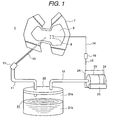
- FIG. 1 is a schematic diagram of an embodiment of the present invention
- FIG. 2 through FIG. 4 are a top view, a bottom view, and an exploded perspective view of the urine receptacle, respectively.
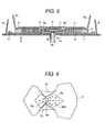
- FIG. 5 is a cross-sectional view taken along the line A-A in FIG. 2.
- FIG. 6 is an enlarged plan view of a support sheet which is a component of the urine receptacle.
- FIG. 7 explains functions of the urine receptacle
- FIG. 8 shows another embodiment of a urine drainage tube.
- FIG. 1 through FIG. 6 show an embodiment of the present invention.
- FIG. 1 is a schematic diagram of an embodiment of the present invention.
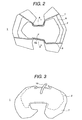
- FIG. 2 is a top view of the urine receptacle
- FIG. 3 is a bottom view of the urine receptacle
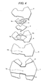
- FIG. 4 is an exploded perspective view of the urine receptacle.
- FIG. 5 is an enlarged cross-sectional view taken along the line A-A in FIG. 2.
- FIG. 6 is an enlarged plan view of a support sheet which is a component of the urine receptacle.
- a urine receptacle 1 which absorbs urine discharged from a wearer's urinating part, not shown, is in the concaved shape, as shown in FIG. 3, and its width at the middle portion in the longitudinal direction (direction of the wearer's front and rear) 2 is narrow so that it is shaped like an hourglass. The reason for this shape is to fit the wearer's crotch.
- the urine receptacle 1 consists of a top sheet 2, perforated urine absorbent sheet 3, urine absorbing space forming sheet 4, support sheet 5, urine absorbent sheet 6, outer sheet 7 and gathers 8.
- the top sheet 2 is made of a liquid-permeable, hard-breathable nonwoven cloth
- the perforated urine absorbent sheet 3 is made of liquid-impermeable, non-breathable vinyl.
- the urine absorbing space forming sheet 4 is made of a rough fibrous material which does not hold liquid
- the support sheet 5 is made of a liquid-impermeable, non-breathable, elastic polyethylene sheet, rubber, or vinyl.
- the urine absorbent sheet 6 is made of a compound material which compounds a liquid-permeable nonwoven cloth, flocculent pulp, and a polymer absorbent, and the outer sheet 7 and gathers 8 are made of liquid-impermeable nonwoven cloths.
- the outer sheet 7 is a thin, liquid-impermeable sheet and is made of a polyethylene film, for example.
- the outer sheet 7 may be simply made of a liquid-impermeable member; however, desirably, an optimal member can be chosen by taking into account stuffiness which may result from the prolonged use.
- the outer surface of the outer sheet 7 is laminated with a soft and smooth surface material (not shown), such as a polypropylene nonwoven cloth, to prevent the wearer from becoming uncomfortable.
- the inner surface of the outer sheet 7 has been treated with a water-repellent material.
- three-dimensional gathers 8 are created such that they are slanted inwardly along the periphery of the outer sheet 7 as shown in FIG. 5. These slantingly provided three-dimensional gathers 8 prevent leaks from the sides caused by the wearer's physical activity or change of posture.
- a through hole 7a through which a urine drainage tube 10 passes is created on the outer sheet 7.
- a urine absorbent sheet 6 adheres to the top surface of the outer sheet 7.
- the urine absorbent sheet 6 is provided to absorb urine which has not been collected by the support sheet 5, thereby preventing urine from wetting the wearer's clothes or bedding and also preventing urine from coming in contact with the wearer's skin.
- a through hole 6a through which a urine drainage tube 10 passes is created on the urine absorbent sheet 6.
- a support sheet 5 adheres to the surface of the urine absorbent sheet 6.
- the support sheet 5 has a concave portion 5b into which the urine absorbing space forming sheet 4 can fit. Furthermore, a urine drainage port 5a to which a urine drainage tube 10 is connected is formed in the concave portion 5b.
- the urine drainage port 5a is formed such that it is located at an approximate center of the perforated urine absorbent sheet 3, which will be described later, on which a large number of urine drainage pores 3a are formed.
- Both sides of the support sheet 5 which fit to the wearer's crotch (urinating part) are loose fitting thereby forming peripheral pieces 5c, as shown in Figures 5 and 6, to prevent urine from leaking from the sides.
- a urine absorbing space forming sheet 4 fits into the concave portion 5b, and a perforated urine absorbent sheet 3 is disposed on the top surface of the urine absorbing space forming sheet 4.
- the support sheet 5 is made of an elastic material such as polyethylene foam.
- the urine absorbing space forming sheet 4 is made of a porous, fibriform skeletal material with no water-absorption capability and the sides of the sheet 4 adhere to the concave portion 5b of the support sheet 5 thereby molding into it.
- the urine absorbing space forming sheet 4 is made of a 5 to 10 mm thick, porous material to ensure that the air space for sucking urine (urine collecting space) is maximized.
- the urine absorbing space forming sheet 4 fits into the concave portion 5b of the support sheet 5. This configuration eliminates clearance or level difference between the urine absorbing space forming sheet 4 and the support sheet 5 thereby preventing urine from remaining.
- a perforated urine absorbent sheet 3 on which a large number of urine drainage pores 3a are formed is disposed on the top surface of the urine absorbing space forming sheet 4.
- the urine absorbing space forming sheet 4 is disposed such that it comes in close contact with the bottom surface of the perforated urine absorbent sheet 3.
- the perforated urine absorbent sheet 3 is a similar shape as the urine absorbing space forming sheet 4, and the bottom surface of its periphery adheres to the support sheet 5 as shown in FIG. 5.
- the urine absorbing space forming sheet 4 is disposed between the perforated urine absorbent sheet 3 and the support sheet 5.
- Urine drainage pores 3a are formed on the perforated urine absorbent sheet 3 between the area where urine is discharged from the urinating part and the vicinity of the buttocks in order to increase the percentage of urine collection as well as to handle spread of urine due to urination while the wearer is lying down on his/her back or sitting. Urine drainage pores 3a are formed at locations with different distances necessary for effectively collecting urine. Furthermore, the diameter of the urine drainage pore 3a can be changed according to its location from which urine is collected; for example, the diameter of the pore near the urinating part can be made larger than that of other pores.
- the top sheet 2 is disposed on the surface of the perforated urine absorbent sheet 3 and a urine sensor 9 is located between the top sheet 2 and the perforated urine absorbent sheet 3.
- the surface of the perforated urine absorbent sheet 3 is covered with the hard-breathable top sheet 2.
- Urine discharged by a wearer is absorbed by the top sheet 2 and then absorbed into urine drainage pores 3a formed on the perforated urine absorbent sheet 3.
- the top sheet 2 is made of a liquid-permeable, hard-breathable nonwoven cloth which is made of, for example, polypropylene and polyolefin polyester blended with cotton so that friction between the wearer's skin and the fabric is minimized.
- a mesh sheet makes up a part of the surface of the nonwoven cloth used as the top sheet 2 where it comes in contact with the wearer's urinating part and the surrounding skin. This is to increase the liquid-absorbent and sweat-absorbent capabilities so that urine can be quickly absorbed by the urine drainage pores 3a formed on the perforated urine absorbent sheet 3 through small pores created in the mesh sheet. Because urine can be quickly absorbed by the perforated urine absorbent sheet 3, the wearer has a minimal amount of discomfort due to moisture around the wearer's urinating part.
- Hard breathability of the top sheet 2 means that the breathability measured according to the General Textile Testing Method's breathability testing method A, prescribed in JIS L1096, 6.27.1, is from 0 to 100 cc/cm 2 /second and preferably from 0 to 50 cc/cm 2 /second when the top sheet 2 is moist.
- the breathability is from 20 to 200 cc/cm 2 /second, preferably from 20 to 100 cc/cm 2 /second, and more preferably from 20 to 50 cc/cm 2 /second.
- being moist is a condition in which moisture content (%) of the top sheet 2 that is obtained by the following equation is 100 % or more
- being dry is a condition in which the top sheet 2 has been left dry in the 20 °C and RH60 % atmosphere, or the condition of, what is called, official moisture regain.
- Moisture content (Weight of moist sheet - Weight of dry sheet)/(Weight of dry sheet)
- one end of the urine drainage tube (first urine drainage means) 10 is connected to the urine drainage port 5a formed on the support sheet 5.
- the urine drainage tube 10 penetrates holes 6a and 7a of the urine absorbent sheet 6 and the outer sheet 7 and the other end is connected to a one-touch joint 13.
- the one-touch joint 13 is mounted to one end of the urine drainage tube (second urine drainage means) 11. This joint 13 connects the other end of the urine drainage tube 10 to the end of the urine drainage tube 11.
- the urine drainage tubes 10 and 11 are made of soft, flexible materials such as soft resin, and the one-touch joint 13 is made of a soft material.
- a urine tank 21 is sealed by a lid 22.
- the other end of the urine drainage tube 11 passes through the lid 22 of the urine tank 21 and is located in the vapor phase area 21a of the urine tank 21.
- One end of the vacuum tube 12 is connected to a vacuum pump 23 and the other end passes through the lid 22 of the urine tank 21 and is located in the vapor phase area 21a of the urine tank 21.
- the vacuum tube 12 is also made of a soft, flexible material.
- the capacity of the urine tank 21 is about 500 cm 3 which can store two separate urinations. This tank also comes in 200 cm 3 or 1000 cm 3 which allows for the prolonged use at night.
- the vacuum pump 23 is driven by a motor 24.
- the motor 24 uses a battery 25 as a driving power source, and is controlled by a control device installed in the control board 26.
- the vacuum pump 23 is small having a diameter of 30 mm ⁇ 70 mm. Voltage of the battery 25 is approximately 6 V.
- a urine sensor 9 detects that urine has been discharged in the top sheet 2. It is electrically conductive and detects the wearer's urination by sensing the resistance value change.
- the urine detection signal detected by the urine sensor 9 is inputted via signal lines 14 and 15 into the control board 26 that controls the vacuum pump 23.
- the signal lines 14 and 15 are connected by a one-touch joint 16.
- the urine receptacle 1 is worn so that the top sheet 2 comes in contact with the urinating part of a wearer (not shown) in his/her underwear.
- the urine tank 21, vacuum pump 23, and the motor 24 can be carried by the wearer or can be placed on or under the bed on which the wearer lies.
- the urine drainage pores 3a of the perforated urine absorbent sheet 3 are formed in such a way that, with the appropriate number of pores of a certain diameter, the urine drainage pores 3a properly maintain negative pressure in the urine absorbing space so as to draw urine into the urine absorbing space by means of a uniform suction force from a wide area of the top sheet 2 which comes in contact with the perforated urine absorbent sheet 3. That is, the perforated urine absorbent sheet 3 is provided in order to uniformly create negative pressure in the urine absorbing space of the urine absorbing space forming sheet 4. Without the perforated urine absorbent sheet 3, urine is exclusively drawn from the vicinity of the urine drainage port 5a (urine drainage tube 10) into the urine drainage tube 10, causing the percentage of urine collection to decrease.
- Urine drawn into the urine drainage tube 10 is further drawn into the urine tank 21 by the negative pressure via the urine drainage tube 11 and stored in the tank.
- the urine tank 21 can be removed by disconnecting the urine drainage tubes 10 and 11 by unlocking the one-touch joint 13 as well as by disconnecting the signal lines 14 and 15 by unlocking the one-touch joint 16.
- the automatic urine disposal device including the urine tank 21 can be carried and urine stored therein can be disposed of.
- the urine tank 21 can be carried by removing the lid 22 from the urine tank 21 and urine stored in the urine tank 21 can be disposed of.
- the used urine receptacle 1 is discarded by disconnecting the urine drainage tube 10 from the urine sensor 9 by unlocking the joints 13 and 16, and the wearer wears a new urine receptacle 1.
- a urine receptacle 1 according to the present invention is designed such that a urine absorbing space forming sheet 4 is disposed between a perforated urine absorbent sheet 3 and a support sheet 5, and urine is drained through a large number of urine drainage pores 3a formed on the perforated urine absorbent sheet 3 and is drawn into a sealed urine tank 21 by means of a vacuum pump 23 via urine drainage tubes 10 and 11.
- This configuration makes it possible to maintain high percentage of urine collection even if the vacuum pump 23 has a low suction force.
- FIG. 8 shows another embodiment of a urine drainage tube 10 which is connected to the urine receptacle 1.
- the urine drainage tube 10 shown in FIG. 8 is different from the urine drainage tube in the above-mentioned embodiment.
- a space-holding material 10B is provided on the inner surface of the outer shell 10A of the urine drainage tube 10.
- This configuration allows the outer shell 10A to be made of a soft material such as liquid-impermeable vinyl and to ensure a space for vacuuming urine without being compressed by a wearer's weight.
- a soft flexible material such as liquid-impermeable rubber or soft resin, must have sufficient rigidity so that it will not be compressed by a wearer's weight.
- the urine drainage tube 10 shown in FIG. 8 can have more flexibility thereby reducing discomfort to the wearer.
- urine discharged in a top sheet is absorbed through a large number of urine drainage pores formed on perforated urine absorbent sheet. Therefore, the percentage of urine collection increases and the amount of urine which remains in the urine receptacle is reduced. With the increase in the percentage of urine collection, a small capacity vacuum pump with a low suction force can drain urine from the urine absorbent material. Therefore, it is possible to drain urine from the urine receptacle without discomfort to the wearer, and the device can be compact and lightweight.
- the device can be compact and lightweight, if it is used as a portable automatic urine disposal device, it will be most efficient. Furthermore, because the device is compact and lightweight and the vacuum pump does not unnecessarily absorb air, noise is minimal and urine can be quietly drained without bothering other patients in the room at night.
- peripheral pieces provided on the support sheet prevent urine from leaking from the sides. Consequently, urine leaks from the sides can be doubly prevented by the peripheral pieces and the gathers formed on the outer sheet.
- the peripheral pieces are not necessarily provided on the support sheet in a practical use of the urine receptacle.
- the top sheet is hard-breathable and the support sheet is non-breathable.
- the pressure in the urine drainage pores of the perforated urine absorbent sheet is made negative, it is obvious that the same effect can be expected when those sheets are slightly breathable.
- the present invention can increase the percentage of urine collection by the urine receptacle and reduce the amount of urine which remains in the urine receptacle. Therefore, a small capacity vacuum pump can drain urine from the urine receptacle. As a result, it is possible to drain urine from the urine receptacle without discomfort to the wearer, and the device can be compact and lightweight.
- the device can be compact and lightweight, if it is used as a portable automatic urine disposal device, it will be most efficient. Furthermore, because the device is compact and lightweight and the vacuum pump does not unnecessarily absorb air, noise is minimal and urine can be quietly drained without bothering other patients in the room at night.
Landscapes
- Health & Medical Sciences (AREA)
- Epidemiology (AREA)
- Engineering & Computer Science (AREA)
- Biomedical Technology (AREA)
- Heart & Thoracic Surgery (AREA)
- Vascular Medicine (AREA)
- Life Sciences & Earth Sciences (AREA)
- Animal Behavior & Ethology (AREA)
- General Health & Medical Sciences (AREA)
- Public Health (AREA)
- Veterinary Medicine (AREA)
- Nursing (AREA)
- Orthopedic Medicine & Surgery (AREA)
- Orthopedics, Nursing, And Contraception (AREA)
- Absorbent Articles And Supports Therefor (AREA)
Abstract
Description
- The present invention relates to an automatic urine disposal device worn by the bedridden elderly, hospitalized patients, physically disabled people, and others who are unable to voluntarily control the bladder or to clean up urine on their own and also relates to a urine receptacle used therefor.
- Because of age, physical disability, hospitalization due to injury or illness, or other physical conditions, people sometimes become unable to voluntarily control the bladder or clean up urine on their own. In those situations, generally, a catheter is directly inserted into the bladder to discharge urine or paper diaper is used.
- When a catheter is directly inserted into the bladder, the wearer feels great discomfort and there is also the probability of injuring the urethra or bladder or the occurrence of an infection. Thus, expertise as well as special sterilized utensils is required.
- When a paper diaper is worn for a prolonged period of time, urine may leak, the wearer can become uncomfortable, get stuffy, or skin troubles such as rashes may occur. To avoid this, the paper diaper must be frequently changed, which will impose considerable physical and mental burdens on both the wearer and the caretaker. Imposed on a daily basis, those physical and mental burdens become a big concern and a significant economical burden as well.
- To avoid those problems, a method has been presented in which urine that has been absorbed by a urine absorbent material of a urine receptacle is discharged by means of a vacuum pump and drawn into a urine tank. The vacuum pump absorbs air in a sealed urine tank and due to the difference between the tank's pressure and the atmospheric pressure, urine absorbed in the urine absorbent material is drained into the urine tank. Automatic urine disposal devices of such configuration have been disclosed in Japanese Application Patent Laid-open Publication No. Hei 07-171182 and No. Hei 11-113946.
- In the prior art disclosed in Japanese Application Patent Laid-open Publication No. Hei 07-171182 and No. Hei 11-113946, urine is drained from one location of the urine absorbent material, and therefore, the percentage of urine collection from the urine receptacle (urine absorbent material) is low. For this reason, the amount of urine which remains in the urine receptacle (urine absorbent material) is large, which makes the wearer feel uncomfortable. To reduce the amount of urine which remains in the urine receptacle, the capacity of the vacuum pump must be increased. Accordingly, it becomes necessary to increase the size and volume of the urine disposal device.
- An object of the present invention is to provide a compact and lightweight automatic urine disposal device which increases the percentage of urine collection by the urine receptacle and also to provide a urine receptacle used therefor.
- To achieve the aforementioned object, the present invention is designed such that it incorporates a urine receptacle in which an urine absorbing space forming sheet is disposed between a perforated urine absorbent sheet for absorbing urine discharged in a top sheet and a support sheet, and urine is drawn through a urine drainage port formed on the support sheet into a sealed urine tank by means of a vacuum pump via a urine drainage tube.
- In other words, in the present invention, a urine absorbent layer is formed by using a urine absorbing space forming sheet disposed between a perforated urine absorbent sheet on which a liquid-permeable, hard-breathable top sheet is located and a non-breathable, liquid-impermeable support sheet, and urine is drained by making the pressure in a large number of urine drainage pores formed on the perforated urine absorbent sheet negative, and then urine is drawn into the urine tank via a urine drainage tube.
- In the urine receptacle used for the present invention, urine which has been discharged in the top sheet is absorbed through a large number of urine drainage pores formed on the perforated urine absorbent sheet. Therefore, the percentage of urine collection from the urine receptacle increases and the amount of urine which remains in the urine receptacle is reduced. With the increase in the percentage of urine collection, a small-capacity vacuum pump with a low suction force can drain urine. Therefore, it is possible to drain urine from the urine receptacle without discomfort to the wearer, and the device can be compact and lightweight.
- FIG. 1 is a schematic diagram of an embodiment of the present invention, and FIG. 2 through FIG. 4 are a top view, a bottom view, and an exploded perspective view of the urine receptacle, respectively. FIG. 5 is a cross-sectional view taken along the line A-A in FIG. 2. FIG. 6 is an enlarged plan view of a support sheet which is a component of the urine receptacle. FIG. 7 explains functions of the urine receptacle, and FIG. 8 shows another embodiment of a urine drainage tube.
- FIG. 1 through FIG. 6 show an embodiment of the present invention. FIG. 1 is a schematic diagram of an embodiment of the present invention. FIG. 2 is a top view of the urine receptacle, FIG. 3 is a bottom view of the urine receptacle, and FIG. 4 is an exploded perspective view of the urine receptacle. FIG. 5 is an enlarged cross-sectional view taken along the line A-A in FIG. 2. FIG. 6 is an enlarged plan view of a support sheet which is a component of the urine receptacle.
- In Figures 1 through 6, a
urine receptacle 1 which absorbs urine discharged from a wearer's urinating part, not shown, is in the concaved shape, as shown in FIG. 3, and its width at the middle portion in the longitudinal direction (direction of the wearer's front and rear) 2 is narrow so that it is shaped like an hourglass. The reason for this shape is to fit the wearer's crotch. - As shown in FIG. 4, the
urine receptacle 1 consists of atop sheet 2, perforated urineabsorbent sheet 3, urine absorbingspace forming sheet 4,support sheet 5, urineabsorbent sheet 6,outer sheet 7 and gathers 8. Thetop sheet 2 is made of a liquid-permeable, hard-breathable nonwoven cloth, and the perforated urineabsorbent sheet 3 is made of liquid-impermeable, non-breathable vinyl. The urine absorbingspace forming sheet 4 is made of a rough fibrous material which does not hold liquid, and thesupport sheet 5 is made of a liquid-impermeable, non-breathable, elastic polyethylene sheet, rubber, or vinyl. Furthermore, the urineabsorbent sheet 6 is made of a compound material which compounds a liquid-permeable nonwoven cloth, flocculent pulp, and a polymer absorbent, and theouter sheet 7 andgathers 8 are made of liquid-impermeable nonwoven cloths. - The
outer sheet 7 is a thin, liquid-impermeable sheet and is made of a polyethylene film, for example. Theouter sheet 7 may be simply made of a liquid-impermeable member; however, desirably, an optimal member can be chosen by taking into account stuffiness which may result from the prolonged use. The outer surface of theouter sheet 7 is laminated with a soft and smooth surface material (not shown), such as a polypropylene nonwoven cloth, to prevent the wearer from becoming uncomfortable. The inner surface of theouter sheet 7 has been treated with a water-repellent material. - Along the periphery of the
outer sheet 7 in the longitudinal direction (direction of the wearer's front and rear), three-dimensional gathers 8 are created such that they are slanted inwardly along the periphery of theouter sheet 7 as shown in FIG. 5. These slantingly provided three-dimensional gathers 8 prevent leaks from the sides caused by the wearer's physical activity or change of posture. In addition, athrough hole 7a through which aurine drainage tube 10 passes is created on theouter sheet 7. - A urine
absorbent sheet 6 adheres to the top surface of theouter sheet 7. The urineabsorbent sheet 6 is provided to absorb urine which has not been collected by thesupport sheet 5, thereby preventing urine from wetting the wearer's clothes or bedding and also preventing urine from coming in contact with the wearer's skin. A throughhole 6a through which aurine drainage tube 10 passes is created on the urineabsorbent sheet 6. - A
support sheet 5 adheres to the surface of the urineabsorbent sheet 6. Thesupport sheet 5 has aconcave portion 5b into which the urine absorbingspace forming sheet 4 can fit. Furthermore, aurine drainage port 5a to which aurine drainage tube 10 is connected is formed in theconcave portion 5b. Theurine drainage port 5a is formed such that it is located at an approximate center of the perforated urineabsorbent sheet 3, which will be described later, on which a large number ofurine drainage pores 3a are formed. - Both sides of the
support sheet 5 which fit to the wearer's crotch (urinating part) are loose fitting thereby formingperipheral pieces 5c, as shown in Figures 5 and 6, to prevent urine from leaking from the sides. In FIG. 6, a urine absorbingspace forming sheet 4 fits into theconcave portion 5b, and a perforated urineabsorbent sheet 3 is disposed on the top surface of the urine absorbingspace forming sheet 4. Thesupport sheet 5 is made of an elastic material such as polyethylene foam. - The urine absorbing
space forming sheet 4 is made of a porous, fibriform skeletal material with no water-absorption capability and the sides of thesheet 4 adhere to theconcave portion 5b of thesupport sheet 5 thereby molding into it. The urine absorbingspace forming sheet 4 is made of a 5 to 10 mm thick, porous material to ensure that the air space for sucking urine (urine collecting space) is maximized. The urine absorbingspace forming sheet 4 fits into theconcave portion 5b of thesupport sheet 5. This configuration eliminates clearance or level difference between the urine absorbingspace forming sheet 4 and thesupport sheet 5 thereby preventing urine from remaining. - A perforated urine
absorbent sheet 3 on which a large number ofurine drainage pores 3a are formed is disposed on the top surface of the urine absorbingspace forming sheet 4. The urine absorbingspace forming sheet 4 is disposed such that it comes in close contact with the bottom surface of the perforated urineabsorbent sheet 3. The perforated urineabsorbent sheet 3 is a similar shape as the urine absorbingspace forming sheet 4, and the bottom surface of its periphery adheres to thesupport sheet 5 as shown in FIG. 5. Thus, the urine absorbingspace forming sheet 4 is disposed between the perforated urineabsorbent sheet 3 and thesupport sheet 5. - Urine drainage pores 3a are formed on the perforated urine
absorbent sheet 3 between the area where urine is discharged from the urinating part and the vicinity of the buttocks in order to increase the percentage of urine collection as well as to handle spread of urine due to urination while the wearer is lying down on his/her back or sitting. Urine drainage pores 3a are formed at locations with different distances necessary for effectively collecting urine. Furthermore, the diameter of theurine drainage pore 3a can be changed according to its location from which urine is collected; for example, the diameter of the pore near the urinating part can be made larger than that of other pores. - The
top sheet 2 is disposed on the surface of the perforated urineabsorbent sheet 3 and aurine sensor 9 is located between thetop sheet 2 and the perforated urineabsorbent sheet 3. The surface of the perforated urineabsorbent sheet 3 is covered with the hard-breathabletop sheet 2. Urine discharged by a wearer is absorbed by thetop sheet 2 and then absorbed intourine drainage pores 3a formed on the perforated urineabsorbent sheet 3. Thetop sheet 2 is made of a liquid-permeable, hard-breathable nonwoven cloth which is made of, for example, polypropylene and polyolefin polyester blended with cotton so that friction between the wearer's skin and the fabric is minimized. - In addition, a mesh sheet makes up a part of the surface of the nonwoven cloth used as the
top sheet 2 where it comes in contact with the wearer's urinating part and the surrounding skin. This is to increase the liquid-absorbent and sweat-absorbent capabilities so that urine can be quickly absorbed by theurine drainage pores 3a formed on the perforated urineabsorbent sheet 3 through small pores created in the mesh sheet. Because urine can be quickly absorbed by the perforated urineabsorbent sheet 3, the wearer has a minimal amount of discomfort due to moisture around the wearer's urinating part. - Herein, hard breathability of the
top sheet 2 will be explained. Hard breathability of thetop sheet 2 means that the breathability measured according to the General Textile Testing Method's breathability testing method A, prescribed in JIS L1096, 6.27.1, is from 0 to 100 cc/cm2/second and preferably from 0 to 50 cc/cm2/second when thetop sheet 2 is moist. When thetop sheet 2 is dry, the breathability is from 20 to 200 cc/cm2/second, preferably from 20 to 100 cc/cm2/second, and more preferably from 20 to 50 cc/cm2/second. - Moreover, "being moist" is a condition in which moisture content (%) of the
top sheet 2 that is obtained by the following equation is 100 % or more, and "being dry" is a condition in which thetop sheet 2 has been left dry in the 20 °C and RH60 % atmosphere, or the condition of, what is called, official moisture regain. - In FIG. 1, one end of the urine drainage tube (first urine drainage means) 10 is connected to the
urine drainage port 5a formed on thesupport sheet 5. Theurine drainage tube 10 penetratesholes absorbent sheet 6 and theouter sheet 7 and the other end is connected to a one-touch joint 13. The one-touch joint 13 is mounted to one end of the urine drainage tube (second urine drainage means) 11. This joint 13 connects the other end of theurine drainage tube 10 to the end of theurine drainage tube 11. Theurine drainage tubes - A
urine tank 21 is sealed by alid 22. The other end of theurine drainage tube 11 passes through thelid 22 of theurine tank 21 and is located in thevapor phase area 21a of theurine tank 21. One end of thevacuum tube 12 is connected to avacuum pump 23 and the other end passes through thelid 22 of theurine tank 21 and is located in thevapor phase area 21a of theurine tank 21. Like theurine drainage tubes vacuum tube 12 is also made of a soft, flexible material. The capacity of theurine tank 21 is about 500 cm3 which can store two separate urinations. This tank also comes in 200 cm3 or 1000 cm3 which allows for the prolonged use at night. - The
vacuum pump 23 is driven by amotor 24. Themotor 24 uses abattery 25 as a driving power source, and is controlled by a control device installed in thecontrol board 26. Thevacuum pump 23 is small having a diameter of 30 mm × 70 mm. Voltage of thebattery 25 is approximately 6 V. - A
urine sensor 9 detects that urine has been discharged in thetop sheet 2. It is electrically conductive and detects the wearer's urination by sensing the resistance value change. The urine detection signal detected by theurine sensor 9 is inputted viasignal lines control board 26 that controls thevacuum pump 23. The signal lines 14 and 15 are connected by a one-touch joint 16. - In this configuration, the
urine receptacle 1 is worn so that thetop sheet 2 comes in contact with the urinating part of a wearer (not shown) in his/her underwear. Theurine tank 21,vacuum pump 23, and themotor 24 can be carried by the wearer or can be placed on or under the bed on which the wearer lies. - When the wearer urinates in this situation, urine discharged in the
urine receptacle 1 is absorbed by the top sheet (nonwoven cloth) 2. When thetop sheet 2 absorbs urine, the space among fibers of thetop sheet 2 is filled with urine. When thetop sheet 2 absorbs urine, theurine sensor 9 is turned on, and a urine detection signal is inputted into thecontrol board 26. The control device installed in thecontrol board 26 activates themotor 24 to drive thevacuum pump 23. - When air in the
urine tank 21 has been discharged by thevacuum pump 23, air pressure in the urine absorbing space inside the urine absorbingspace forming sheet 4 decreases, creating negative pressure in a large number ofurine drainage pores 3a formed on the perforated urineabsorbent sheet 3. Thetop sheet 2 is hard-breathable and theouter sheet 7 is non-breathable. Therefore, pressure in the urine absorbing space of the urine absorbingspace forming sheet 4 efficiently decreases. - When pressure in the urine absorbing space of the urine absorbing
space forming sheet 4 becomes negative, a uniform suction force is created in all of theurine drainage pores 3a. Consequently, it is possible to draw urine from aurine drainage pore 3a away from theurine drainage port 5a to the urine absorbing space. As shown in FIG. 7, urine 20 (indicated by horizontally hatched lines) flows into the pores of thefibrous material 4a which create a urine absorbing space 4A of the urine absorbingspace forming sheet 4 and flows in the direction indicated by thick arrows. Urine absorbed by the urine absorbingspace forming sheet 4 is drawn into aurine drainage tube 10 by means of a suction force due to negative pressure. - The
urine drainage pores 3a of the perforated urineabsorbent sheet 3 are formed in such a way that, with the appropriate number of pores of a certain diameter, the urine drainage pores 3a properly maintain negative pressure in the urine absorbing space so as to draw urine into the urine absorbing space by means of a uniform suction force from a wide area of thetop sheet 2 which comes in contact with the perforated urineabsorbent sheet 3. That is, the perforated urineabsorbent sheet 3 is provided in order to uniformly create negative pressure in the urine absorbing space of the urine absorbingspace forming sheet 4. Without the perforated urineabsorbent sheet 3, urine is exclusively drawn from the vicinity of theurine drainage port 5a (urine drainage tube 10) into theurine drainage tube 10, causing the percentage of urine collection to decrease. - Urine drawn into the
urine drainage tube 10 is further drawn into theurine tank 21 by the negative pressure via theurine drainage tube 11 and stored in the tank. Theurine tank 21 can be removed by disconnecting theurine drainage tubes signal lines touch joint 16. Thus, the automatic urine disposal device including theurine tank 21 can be carried and urine stored therein can be disposed of. Theurine tank 21 can be carried by removing thelid 22 from theurine tank 21 and urine stored in theurine tank 21 can be disposed of. - Moreover, after the wearer has worn the
urine receptacle 1 for a day or when it became dirty due to defecation, the usedurine receptacle 1 is discarded by disconnecting theurine drainage tube 10 from theurine sensor 9 by unlocking thejoints new urine receptacle 1. - A
urine receptacle 1 according to the present invention is designed such that a urine absorbingspace forming sheet 4 is disposed between a perforated urineabsorbent sheet 3 and asupport sheet 5, and urine is drained through a large number ofurine drainage pores 3a formed on the perforated urineabsorbent sheet 3 and is drawn into a sealedurine tank 21 by means of avacuum pump 23 viaurine drainage tubes vacuum pump 23 has a low suction force. - FIG. 8 shows another embodiment of a
urine drainage tube 10 which is connected to theurine receptacle 1. Theurine drainage tube 10 shown in FIG. 8 is different from the urine drainage tube in the above-mentioned embodiment. In FIG. 8, a space-holdingmaterial 10B is provided on the inner surface of theouter shell 10A of theurine drainage tube 10. This configuration allows theouter shell 10A to be made of a soft material such as liquid-impermeable vinyl and to ensure a space for vacuuming urine without being compressed by a wearer's weight. Furthermore, in the aforementioned embodiment, a soft flexible material, such as liquid-impermeable rubber or soft resin, must have sufficient rigidity so that it will not be compressed by a wearer's weight. However, theurine drainage tube 10 shown in FIG. 8 can have more flexibility thereby reducing discomfort to the wearer. - As state above, in the urine receptacle used for the present invention, urine discharged in a top sheet is absorbed through a large number of urine drainage pores formed on perforated urine absorbent sheet. Therefore, the percentage of urine collection increases and the amount of urine which remains in the urine receptacle is reduced. With the increase in the percentage of urine collection, a small capacity vacuum pump with a low suction force can drain urine from the urine absorbent material. Therefore, it is possible to drain urine from the urine receptacle without discomfort to the wearer, and the device can be compact and lightweight.
- Since the device can be compact and lightweight, if it is used as a portable automatic urine disposal device, it will be most efficient. Furthermore, because the device is compact and lightweight and the vacuum pump does not unnecessarily absorb air, noise is minimal and urine can be quietly drained without bothering other patients in the room at night.
- Furthermore, in the aforementioned embodiments, peripheral pieces provided on the support sheet prevent urine from leaking from the sides. Consequently, urine leaks from the sides can be doubly prevented by the peripheral pieces and the gathers formed on the outer sheet. However, it is obvious that the peripheral pieces are not necessarily provided on the support sheet in a practical use of the urine receptacle.
- Moreover, in the aforementioned embodiments, the top sheet is hard-breathable and the support sheet is non-breathable. However, if the pressure in the urine drainage pores of the perforated urine absorbent sheet is made negative, it is obvious that the same effect can be expected when those sheets are slightly breathable.
- The present invention can increase the percentage of urine collection by the urine receptacle and reduce the amount of urine which remains in the urine receptacle. Therefore, a small capacity vacuum pump can drain urine from the urine receptacle. As a result, it is possible to drain urine from the urine receptacle without discomfort to the wearer, and the device can be compact and lightweight.
- Since the device can be compact and lightweight, if it is used as a portable automatic urine disposal device, it will be most efficient. Furthermore, because the device is compact and lightweight and the vacuum pump does not unnecessarily absorb air, noise is minimal and urine can be quietly drained without bothering other patients in the room at night.
Claims (14)
- An automatic urine disposal device for absorbing urine collected in a urine receptacle (1) by means of a vacuum pump (23) and directing it to a urine tank (21), said urine receptacle (1) comprising
a top sheet (2) disposed on said urine receptacle's surface which comes in contact with the wearer's skin,
a perforated urine absorbent sheet (3) on which a large number of urine drainage pores (3a) for absorbing urine discharged in said top sheet are formed,
a support sheet (5) disposed on said top sheet's opposite side which does not come in contact with the wearer's skin, and
a urine absorbing space forming sheet (4) which is disposed closer to the support sheet (5) than said perforated urine absorbent sheet (3), characterized in that
said urine tank (21) is sealed,
said support sheet (5) has a first urine drainage means (10),
a second urine drainage means (11) for directing urine into said urine tank (21) is connected to said first urine drainage means (10), and
said vacuum pump (23) vacuums the inside of said urine tank (21). - An automatic urine disposal device according to claim 1, characterized in that said second urine drainage means (11) is a tube, and said vacuum pump (23) absorbs air from said urine tank (21).
- An automatic urine disposal device according to claim 1 or 2,
characterized in that
said urine receptacle (1) has a urine sensor (9) for detecting that urine has been discharged in said urine receptacle (1) and activating said vacuum pump (23),
said support sheet (5) is liquid-impermeable and non-breathable, and
said vacuum pump (23) decreases pressure in said urine tank (21) and draws urine from a urine drainage means formed on said support sheet to said urine tank. - An automatic urine disposal device according to any of the preceding claims, characterized in that
said urine tank (21) has a lid (22) for sealing said urine tank,
said second urine drainage means (11) directs urine from a first urine drainage means (10) formed on said support sheet (5) to said urine tank via said lid,
said vacuum pump (23) makes pressure of the urine drainage pores of said perforated urine absorbent sheet (3) negative and absorbs urine into said urine tank. - An automatic urine disposal device according to any of the preceding claims, characterized in that
said top sheet (2) is liquid-permeable and hard-breathable,
said urine absorbing space forming sheet (4) is fibrous, and
said first urine drainage means (10) is connected to said second urine drainage means (11) by a joint (13). - An automatic urine disposal device according to any of the preceding claims, characterized in that
said top sheet (2) covers the surface of said perforated urine absorbent sheet (3),
said urine absorbing space forming sheet (4) is disposed between the bottom surface of said perforated urine absorbent sheet (3) and said support sheet (5). - An automatic urine disposal device according to any of the preceding claims, characterized in that
said top sheet (2) is hard-breathable, and
said support sheet (5) is liquid-impermeable. - An automatic urine disposal device according to any of the preceding claims, characterized in that
said top sheet (2) is liquid-permeable and hard-breathable and covers the surface of said perforated urine absorbent sheet (3),
said urine absorbing space forming sheet (4) is disposed such that it comes in close contact with the bottom surface of said perforated urine absorbent sheet (3) thereby forming a urine absorbing space,
said support sheet (5) is liquid-impermeable and supports said urine absorbing space forming sheet (4), and
said urine receptacle has an outer sheet (7) which holds the aforementioned sheets. - A urine receptacle (1) used for an automatic urine disposal device to absorb urine discharged from a wearer's urinating part, said urine receptacle comprising
a perforated urine absorbent sheet (3) for absorbing discharged urine,
a top sheet (2) which covers the surface of said perforated urine absorbent sheet (3),
a urine absorbing space forming sheet (4) which is disposed such that it comes in close contact with the bottom surface of said perforated urine absorbent sheet (3), and
a liquid-impermeable support sheet (5) which supports said urine absorbing space forming sheet and has a urine drainage means. - A urine receptacle (1) according to claim 9, characterized in that
said perforated urine absorbent sheet (3) and said support sheet (5) are liquid-impermeable, and
said top sheet (2) is hard-breathable. - A urine receptacle (1) according to claim 9 or 10, characterized in that
said perforated urine absorbent sheet (3)and said support sheet (5) are liquid-impermeable and non-breathable, and
said top sheet (2) is liquid-permeable and hard-breathable. - A urine receptacle according to any of claims 9 - 11, characterized in that
said urine absorbing space forming sheet (4) is made of a fibrous material, and
an outer sheet (7) is provided to support said top sheet, said perforated urine absorbent sheet, said urine absorbing space forming sheet and said support sheet. - A urine receptacle according to any of claims 9 - 12, characterized in that
gathers are provided along the periphery of said support sheet. - A urine receptacle according to any of claims 9 - 13, characterized in that
said urine absorbing space forming sheet (4) fits into the concave portion of said support sheet (5),
said outer sheet (7) contains said top sheet (2), said perforated urine absorbent sheet (3), said urine absorbing space forming sheet (4) and said support sheet (5), and
said urine absorbent sheet (6) is disposed between said support sheet (5) and said outer sheet (7).
Applications Claiming Priority (2)
| Application Number | Priority Date | Filing Date | Title |
|---|---|---|---|
| JP2003166671A JP4267379B2 (en) | 2003-06-11 | 2003-06-11 | Automatic urination processing apparatus and urine receiver used therefor |
| JP2003166671 | 2003-06-11 |
Publications (1)
| Publication Number | Publication Date |
|---|---|
| EP1486184A1 true EP1486184A1 (en) | 2004-12-15 |
Family
ID=33296849
Family Applications (1)
| Application Number | Title | Priority Date | Filing Date |
|---|---|---|---|
| EP04013652A Withdrawn EP1486184A1 (en) | 2003-06-11 | 2004-06-09 | Automatic urine disposal device and urine receptacle used therefor |
Country Status (7)
| Country | Link |
|---|---|
| US (1) | US20040254547A1 (en) |
| EP (1) | EP1486184A1 (en) |
| JP (1) | JP4267379B2 (en) |
| KR (1) | KR20040106230A (en) |
| CN (1) | CN1572269A (en) |
| SG (1) | SG118284A1 (en) |
| TW (1) | TWI235654B (en) |
Cited By (4)
| Publication number | Priority date | Publication date | Assignee | Title |
|---|---|---|---|---|
| EP1616542A1 (en) * | 2004-07-15 | 2006-01-18 | Uni-Charm Corporation | Urine receiver and urine collection processing system implementing urine receiver |
| WO2008078117A1 (en) * | 2006-12-22 | 2008-07-03 | Iqol Design Limited | Incontinence aid |
| EP1908439A4 (en) * | 2005-07-14 | 2010-06-23 | Uni Charm Corp | Urine receiver |
| GB2539173A (en) * | 2015-05-11 | 2016-12-14 | Lise John-Baptiste Ange | Convenience pad |
Families Citing this family (93)
| Publication number | Priority date | Publication date | Assignee | Title |
|---|---|---|---|---|
| US20060041238A1 (en) * | 2004-08-23 | 2006-02-23 | Bowen Michael L | Fluid collection system and method |
| CN105268043B (en) * | 2009-05-27 | 2019-03-12 | E·伯克 | For removing and accommodating the device and method of slop |
| US9456937B2 (en) * | 2011-12-01 | 2016-10-04 | Ann Marie Ellis | Hand-held female urine collector |
| US11090183B2 (en) | 2014-11-25 | 2021-08-17 | Purewick Corporation | Container for collecting liquid for transport |
| US10226376B2 (en) | 2014-03-19 | 2019-03-12 | Purewick Corporation | Apparatus and methods for receiving discharged urine |
| US10390989B2 (en) | 2014-03-19 | 2019-08-27 | Purewick Corporation | Apparatus and methods for receiving discharged urine |
| US11376152B2 (en) | 2014-03-19 | 2022-07-05 | Purewick Corporation | Apparatus and methods for receiving discharged urine |
| US11806266B2 (en) | 2014-03-19 | 2023-11-07 | Purewick Corporation | Apparatus and methods for receiving discharged urine |
| US10952889B2 (en) | 2016-06-02 | 2021-03-23 | Purewick Corporation | Using wicking material to collect liquid for transport |
| US9713548B2 (en) * | 2014-06-04 | 2017-07-25 | Sandra A. Amerson | Urine collection assembly |
| CN104188762A (en) * | 2014-08-14 | 2014-12-10 | 珠海尚尔生物科技有限公司 | Novel nappy/paper diaper/paper urine mat |
| AU2017275649B2 (en) | 2016-06-02 | 2019-08-01 | Purewick Corporation | Apparatus and methods for receiving discharged urine |
| USD928946S1 (en) | 2016-06-02 | 2021-08-24 | Purewick Corporation | Urine receiving apparatus |
| US10973678B2 (en) * | 2016-07-27 | 2021-04-13 | Purewick Corporation | Apparatus and methods for receiving discharged urine |
| US10376406B2 (en) | 2016-07-27 | 2019-08-13 | Purewick Corporation | Male urine collection device using wicking material |
| US10376407B2 (en) | 2016-08-16 | 2019-08-13 | Purewick Corporation | Using wicking material to collect urine from a male for transport |
| WO2018144463A1 (en) | 2017-01-31 | 2018-08-09 | Purewick Corporation | Apparatus and methods for receiving discharged urine |
| WO2018152156A1 (en) | 2017-02-14 | 2018-08-23 | Sage Products, Llc | Devices and methods for urine collection |
| CN106821654A (en) * | 2017-03-16 | 2017-06-13 | 刘珉恺 | One kind auxiliary urinates device and method |
| USD882768S1 (en) | 2017-09-08 | 2020-04-28 | Sage Products, Llc | Urine collection device |
| JP7072084B2 (en) | 2018-05-01 | 2022-05-19 | ピュアウィック コーポレイション | Fluid collectors, related systems, and related methods |
| US11944740B2 (en) | 2018-05-01 | 2024-04-02 | Purewick Corporation | Fluid collection devices, related systems, and related methods |
| EP3787571B1 (en) * | 2018-05-01 | 2022-06-01 | Purewick Corporation | Fluid collection garments |
| AU2019262939A1 (en) | 2018-05-01 | 2020-11-26 | Purewick Corporation | Fluid collection devices, systems, and methods |
| EP3787569B1 (en) * | 2018-05-01 | 2025-07-16 | Purewick Corporation | Fluid collection devices and systems |
| AU2019262945B2 (en) | 2018-05-01 | 2022-08-25 | Purewick Corporation | Fluid collection devices and methods of using the same |
| EP3787572B1 (en) * | 2018-05-02 | 2022-07-06 | Purewick Corporation | Fluid collection devices, systems, and methods |
| KR200490630Y1 (en) * | 2018-12-31 | 2019-12-09 | (주)한독메디텍 | Surgical cover for perineal region having size variable function |
| USD929578S1 (en) | 2019-06-06 | 2021-08-31 | Purewick Corporation | Urine collection assembly |
| CA3143904C (en) * | 2019-06-21 | 2023-11-28 | Purewick Corporation | Fluid collection devices including a base securement area, and related systems and methods |
| US20220273482A1 (en) * | 2019-07-09 | 2022-09-01 | Purewick Corporation | Fluid collection devices including an opening having an increased width, and sustems and methods of use |
| ES2961269T3 (en) | 2019-07-11 | 2024-03-11 | Purewick Corp | Liquid collection devices and systems |
| WO2021016026A1 (en) | 2019-07-19 | 2021-01-28 | Purewick Corporation | Fluid collection devices including at least one shape memory material |
| CA3153479A1 (en) | 2019-09-06 | 2021-03-11 | Sage Products Llc | Devices and systems for urine collection |
| EP4051190B1 (en) | 2019-10-28 | 2024-05-22 | Purewick Corporation | Fluid collection assemblies including a sample port |
| EP4559443A3 (en) | 2020-01-03 | 2025-06-18 | Purewick Corporation | Urine collection devices having a relatively wide portion and an elongated portion and related methods |
| WO2021150145A1 (en) * | 2020-01-23 | 2021-07-29 | Светлана Алексеевна ЛЕБЕДЕВА | Portable female urination device |
| RU197838U9 (en) * | 2020-01-23 | 2021-04-07 | Светлана Алексеевна Лебедева | UNIVERSAL PORTABLE DEVICE FOR MECHANICAL DIVISION OF URINE IN WOMEN |
| US20230049924A1 (en) * | 2020-01-30 | 2023-02-16 | Purewick Corporation | Fluid coolection assemblies including a skirt |
| EP4096611B1 (en) | 2020-01-31 | 2025-05-14 | C. R. Bard, Inc. | Drainage bag height actuator |
| WO2021188817A1 (en) | 2020-03-19 | 2021-09-23 | Purewick Corporation | Fluid collection assemblies including one or more movement enhancing features |
| US12521288B2 (en) | 2020-03-26 | 2026-01-13 | Purewick Corporation | Multi-layer urine capture device and related methods |
| WO2021207621A1 (en) * | 2020-04-10 | 2021-10-14 | Purewick Corporation | Fluid collection assemblies including one or more leak prevention features |
| US12472090B2 (en) | 2020-04-17 | 2025-11-18 | Purewick Corporation | Female external catheter devices having a urethral cup, and related systems and methods |
| US12465514B2 (en) | 2020-04-17 | 2025-11-11 | Purewick Corporation | Fluid collection devices, systems, and methods securing a protruding portion in position for use |
| WO2021211801A1 (en) | 2020-04-17 | 2021-10-21 | Purewick Corporation | Fluid collection assemblies including a fluid impermeable barrier having a sump and a base |
| US12491104B2 (en) | 2020-04-20 | 2025-12-09 | Purewick Corporation | Fluid collection devices adjustable between a vacuum-based orientation and a gravity-based orientation, and related systems and methods |
| US12048643B2 (en) | 2020-05-27 | 2024-07-30 | Purewick Corporation | Fluid collection assemblies including at least one inflation device and methods and systems of using the same |
| USD967409S1 (en) | 2020-07-15 | 2022-10-18 | Purewick Corporation | Urine collection apparatus cover |
| US12440371B2 (en) * | 2020-08-06 | 2025-10-14 | Purewick Corporation | Fluid collection system including a garment and a fluid collection device |
| US12350187B2 (en) * | 2020-08-11 | 2025-07-08 | Purewick Corporation | Fluid collection assemblies defining waist and leg openings |
| US12121669B2 (en) | 2020-08-14 | 2024-10-22 | C. R. Bard, Inc. | Assisted fluid drainage system |
| EP4210643A1 (en) | 2020-09-09 | 2023-07-19 | Purewick Corporation | Fluid collection devices, systems, and methods |
| US12156792B2 (en) | 2020-09-10 | 2024-12-03 | Purewick Corporation | Fluid collection assemblies including at least one inflation device |
| US11801186B2 (en) | 2020-09-10 | 2023-10-31 | Purewick Corporation | Urine storage container handle and lid accessories |
| US12042423B2 (en) | 2020-10-07 | 2024-07-23 | Purewick Corporation | Fluid collection systems including at least one tensioning element |
| US12569365B2 (en) | 2020-10-21 | 2026-03-10 | Purewick Corporation | Fluid collection assemblies including at least one shape memory material disposed in the conduit |
| US12257174B2 (en) | 2020-10-21 | 2025-03-25 | Purewick Corporation | Fluid collection assemblies including at least one of a protrusion or at least one expandable material |
| US12440370B2 (en) | 2020-10-21 | 2025-10-14 | Purewick Corporation | Apparatus with compressible casing for receiving discharged urine |
| US12208031B2 (en) | 2020-10-21 | 2025-01-28 | Purewick Corporation | Adapters for fluid collection devices |
| US12048644B2 (en) | 2020-11-03 | 2024-07-30 | Purewick Corporation | Apparatus for receiving discharged urine |
| US12070432B2 (en) | 2020-11-11 | 2024-08-27 | Purewick Corporation | Urine collection system including a flow meter and related methods |
| US12318552B2 (en) | 2020-11-18 | 2025-06-03 | C. R. Bard, Inc. | Collapsible thin-walled valve for drainage control |
| US12245967B2 (en) | 2020-11-18 | 2025-03-11 | Purewick Corporation | Fluid collection assemblies including an adjustable spine |
| US11944737B2 (en) | 2020-11-24 | 2024-04-02 | C. R. Bard, Inc. | Air venting meter lid adapter |
| US12109353B2 (en) | 2020-12-04 | 2024-10-08 | C. R. Bard, Inc. | Dynamic pressure response and catheter occlusion system |
| US12128188B2 (en) | 2020-12-21 | 2024-10-29 | C. R. Bard, Inc. | Dynamic pressure response system and method for measuring residual fluid |
| US12599495B2 (en) | 2021-01-05 | 2026-04-14 | Purewick Corporation | Male external catheter with attachment interface configured to bias against penis |
| US12268627B2 (en) | 2021-01-06 | 2025-04-08 | Purewick Corporation | Fluid collection assemblies including at least one securement body |
| JP2024503636A (en) * | 2021-01-07 | 2024-01-26 | ピュアウィック コーポレイション | Wheelchair-secure urine collection system and related methods |
| US11931541B2 (en) | 2021-01-08 | 2024-03-19 | C. R. Bard, Inc. | Connector for selective occlusion of drainage tube |
| US11992599B2 (en) | 2021-01-08 | 2024-05-28 | C. R. Bard, Inc. | Urinary drainage system with air pressure apparatus |
| EP4349306A3 (en) * | 2021-01-19 | 2024-06-05 | Purewick Corporation | Variable fit fluid collection devices |
| US12178735B2 (en) | 2021-02-09 | 2024-12-31 | Purewick Corporation | Noise reduction for a urine suction system |
| EP4274524B1 (en) * | 2021-02-26 | 2024-08-28 | Purewick Corporation | A male fluid collection device configured as a male urine collection device |
| US12558472B2 (en) | 2021-03-05 | 2026-02-24 | Purewick Corporation | Portable fluid collection systems with storage and related methods |
| US12551385B2 (en) | 2021-03-05 | 2026-02-17 | Purewick Corporation | Fluid collection assembly including a tube having porous wicking material for improved fluid transport |
| US12458525B2 (en) | 2021-03-10 | 2025-11-04 | Purewick Corporation | Acoustic silencer for a urine suction system |
| US11938054B2 (en) | 2021-03-10 | 2024-03-26 | Purewick Corporation | Bodily waste and fluid collection with sacral pad |
| CN113041004A (en) * | 2021-03-15 | 2021-06-29 | 深圳航天科技创新研究院 | Nursing wearing device and lying and defecating nursing robot |
| US12029677B2 (en) | 2021-04-06 | 2024-07-09 | Purewick Corporation | Fluid collection devices having a collection bag, and related systems and methods |
| US11717435B2 (en) * | 2021-04-19 | 2023-08-08 | Lyv Life Inc. | Menstrual disc and methods of use |
| US12233003B2 (en) | 2021-04-29 | 2025-02-25 | Purewick Corporation | Fluid collection assemblies including at least one length adjusting feature |
| US12251333B2 (en) | 2021-05-21 | 2025-03-18 | Purewick Corporation | Fluid collection assemblies including at least one inflation device and methods and systems of using the same |
| US20220370237A1 (en) * | 2021-05-24 | 2022-11-24 | Purewick Corporation | Non-invasive fluid collection device for improved fluid collection for ambulatory users |
| US12324767B2 (en) | 2021-05-24 | 2025-06-10 | Purewick Corporation | Fluid collection assembly including a customizable external support and related methods |
| US12150885B2 (en) | 2021-05-26 | 2024-11-26 | Purewick Corporation | Fluid collection system including a cleaning system and methods |
| US12575960B2 (en) | 2021-06-24 | 2026-03-17 | Purewick Corporation | Urine collection systems having one or more of volume, pressure, or flow indicators, and related methods |
| US12491103B2 (en) | 2021-07-14 | 2025-12-09 | C. R. Bard, Inc. | Urinary collection system |
| US12551366B2 (en) | 2021-08-02 | 2026-02-17 | Purewick Corporation | Fluid collection devices having multiple fluid collection regions, and related systems and methods |
| US12594062B2 (en) | 2021-09-08 | 2026-04-07 | Purewick Corporation | Fluid collection assemblies including an extension |
| US12214117B2 (en) | 2021-09-10 | 2025-02-04 | C. R. Bard, Inc. | Automated urinary output monitoring system |
| EP4586974A1 (en) * | 2022-09-16 | 2025-07-23 | Purewick Corporation | Urine collection assembly including a porous material and method to manufacture the urine collection assembly |
Citations (4)
| Publication number | Priority date | Publication date | Assignee | Title |
|---|---|---|---|---|
| EP0312118A2 (en) * | 1987-10-16 | 1989-04-19 | Kimberly-Clark Corporation | Absorbent article |
| GB2244653A (en) * | 1990-06-08 | 1991-12-11 | Kao Corp | Absorbent article |
| WO1993009736A2 (en) * | 1991-11-20 | 1993-05-27 | Davstar California, Inc. | Improved pad and pad tube connector for the management of urinary incontinence |
| US5911222A (en) * | 1992-08-07 | 1999-06-15 | Bristol-Myers Squibb | Liquid removal system |
Family Cites Families (3)
| Publication number | Priority date | Publication date | Assignee | Title |
|---|---|---|---|---|
| US4747166A (en) * | 1987-05-15 | 1988-05-31 | Kuntz David H | Fluid aspiration system for the management of urinary incontinence |
| US6569133B2 (en) * | 2000-04-06 | 2003-05-27 | Uroscientific, Inc. | Urine management system for human females |
| US6685681B2 (en) * | 2000-11-29 | 2004-02-03 | Hill-Rom Services, Inc. | Vacuum therapy and cleansing dressing for wounds |
-
2003
- 2003-06-11 JP JP2003166671A patent/JP4267379B2/en not_active Expired - Fee Related
-
2004
- 2004-06-07 TW TW093116332A patent/TWI235654B/en not_active IP Right Cessation
- 2004-06-08 SG SG200404070A patent/SG118284A1/en unknown
- 2004-06-09 EP EP04013652A patent/EP1486184A1/en not_active Withdrawn
- 2004-06-09 US US10/863,268 patent/US20040254547A1/en not_active Abandoned
- 2004-06-10 KR KR1020040042395A patent/KR20040106230A/en not_active Ceased
- 2004-06-11 CN CNA2004100490223A patent/CN1572269A/en active Pending
Patent Citations (4)
| Publication number | Priority date | Publication date | Assignee | Title |
|---|---|---|---|---|
| EP0312118A2 (en) * | 1987-10-16 | 1989-04-19 | Kimberly-Clark Corporation | Absorbent article |
| GB2244653A (en) * | 1990-06-08 | 1991-12-11 | Kao Corp | Absorbent article |
| WO1993009736A2 (en) * | 1991-11-20 | 1993-05-27 | Davstar California, Inc. | Improved pad and pad tube connector for the management of urinary incontinence |
| US5911222A (en) * | 1992-08-07 | 1999-06-15 | Bristol-Myers Squibb | Liquid removal system |
Cited By (6)
| Publication number | Priority date | Publication date | Assignee | Title |
|---|---|---|---|---|
| EP1616542A1 (en) * | 2004-07-15 | 2006-01-18 | Uni-Charm Corporation | Urine receiver and urine collection processing system implementing urine receiver |
| US7220250B2 (en) | 2004-07-15 | 2007-05-22 | Uni-Charm Corporation | Urine receiver and urine collection processing system implementing urine receiver |
| EP1908439A4 (en) * | 2005-07-14 | 2010-06-23 | Uni Charm Corp | Urine receiver |
| US8388588B2 (en) | 2005-07-14 | 2013-03-05 | Unicharm Corporation | Urine receiver |
| WO2008078117A1 (en) * | 2006-12-22 | 2008-07-03 | Iqol Design Limited | Incontinence aid |
| GB2539173A (en) * | 2015-05-11 | 2016-12-14 | Lise John-Baptiste Ange | Convenience pad |
Also Published As
| Publication number | Publication date |
|---|---|
| CN1572269A (en) | 2005-02-02 |
| TW200505400A (en) | 2005-02-16 |
| JP2005000364A (en) | 2005-01-06 |
| TWI235654B (en) | 2005-07-11 |
| KR20040106230A (en) | 2004-12-17 |
| JP4267379B2 (en) | 2009-05-27 |
| SG118284A1 (en) | 2006-01-27 |
| US20040254547A1 (en) | 2004-12-16 |
Similar Documents
| Publication | Publication Date | Title |
|---|---|---|
| EP1486184A1 (en) | Automatic urine disposal device and urine receptacle used therefor | |
| US7390320B2 (en) | Automatic urine disposal device and urine receptacle used therefor | |
| US7749205B2 (en) | Automatic urine disposal device and urine receptacle used therefor | |
| KR101184840B1 (en) | Urine receiver and urine collection processing system implementing urine reciever | |
| EP1520566B1 (en) | Automatic urine disposal device and urine receptacle used thereof | |
| EP0653928B1 (en) | Liquid removal system | |
| US7695460B2 (en) | Negative pressure urine receiver | |
| JP2004267530A (en) | Automatic urination processing device and urine receiver used therefor | |
| JP5466648B2 (en) | Waste fluid detection device | |
| JP4316902B2 (en) | Automatic urination processing apparatus and urine receiver used therefor | |
| JP4317167B2 (en) | Automatic urination processing apparatus and urine receiver used therefor | |
| HK1069101B (en) | Automatic urine disposal device and urine receptacle used therefor | |
| JP2010069137A (en) | Wearing article | |
| HK1070552A (en) | Automatic urine disposal device and urine receptacle used therefor |
Legal Events
| Date | Code | Title | Description |
|---|---|---|---|
| PUAI | Public reference made under article 153(3) epc to a published international application that has entered the european phase |
Free format text: ORIGINAL CODE: 0009012 |
|
| AK | Designated contracting states |
Kind code of ref document: A1 Designated state(s): AT BE BG CH CY CZ DE DK EE ES FI FR GB GR HU IE IT LI LU MC NL PL PT RO SE SI SK TR |
|
| AX | Request for extension of the european patent |
Extension state: AL HR LT LV MK |
|
| 17P | Request for examination filed |
Effective date: 20050406 |
|
| 17Q | First examination report despatched |
Effective date: 20050602 |
|
| AKX | Designation fees paid |
Designated state(s): CH DE FR GB LI NL SE |
|
| STAA | Information on the status of an ep patent application or granted ep patent |
Free format text: STATUS: THE APPLICATION IS DEEMED TO BE WITHDRAWN |
|
| 18D | Application deemed to be withdrawn |
Effective date: 20051013 |